


UNITRODE UCC15701, UCC15702, UCC25701, UCC25702, UCC35701 Technical data
...
UCC15701/2
UCC25701/2
UCC35701/2
Advanced Voltage Mode Pulse Width Modulator
DESCRIPTION
The UCC35701/UCC35702 family of pulse width modulators is intended for
isolated switching power supplies using primary side control. They can be
used for both off-line applications and DC/DC converter designs such as in
a distributed power system architecture or as a telecom power source.
The devices feature low startup current, allowing for efficient off-line start
-
ing, yet have sufficient output drive to switch power MOSFETs in excess of
500kHz.
Voltage feed forward compensation is operational over a 5:1 input range
and provides fast and accurate response to input voltage changes over a
4:1 range. An accurate volt-second clamp and maximum duty cycle limit
are also featured.
Fault protection is provided by pulse by pulse current limiting as well as the
ability to latch off after a programmable number of repetitive faults has oc
-
curred.
Two UVLO options are offered. UCC35701 family has turn-on and turn-off
thresholds of 13V/9V and UCC35702 family has thresholds of 9.6V/8.8V.
The UCC35701/2 and the UCC25701/2 are offered in the 14 pin SOIC (D),
14 pin PDIP (N) or in 14 pin TSSOP (PW) packages. The UCC15701/2 is
offered in the 14 pin CDIP (J) package.
3VDD
12 VREF
8FB
4OUT
2ILIM
5PGND
C3
1 COUNT
CF
14 SS
CS
11 SYNC
9 VSCLAMP
VREF
10 CT
CT
7RT
6
VFF
13GND
V
IN
SUPPLY
V
IN
RETURN
RGND
R10
RCS
R8
R7
R6
C2
R8
R
F
R5
R4
R3
R2
R1
V
OUT
UCC35701
C1
C4
C6
R12
C6
C5
R11
R13
C7
R14
V
OUT
R15
TYPICAL APPLICATION DIAGRAM
SLUS293A - JANUARY 2000
FEATURES
•
700kHz Operation
•
Integrated Oscillator/ Voltage Feed
Forward Compensation
•
Accurate Duty Cycle Limit
•
Accurate Volt-second Clamp
•
Optocoupler Interface
•
Fault Counting Shutdown
•
Fault Latch off or Automatic Shutdown
•
Soft Stop Optimized for Synchronous
Rectification
•
1A Peak Gate Drive Output
• 130µA Start-up Current
• 750µA Operating Current
UDG-98005-1
application
INFO
available
查询UCC15701供应商
2
UCC15701/2
UCC25701/2
UCC35701/2
ABSOLUTE MAXIMUM RATINGS
Supply voltage (Supply current limited to 20mA) . . . . . . . . 15V
Supply Current. . . . . . . . . . . . . . . . . . . . . . . . . . . . . . . . . 20mA
Input pins ( ILIM,VFF,RT,CT,VSCLAMP,SYNC,SS) . . . . . . 6V
Output Current (OUT) DC. . . . . . . . . . . . . . . . . . . . . +/–180mA
Output Current (OUT) Pulse (0.5ms) . . . . . . . . . . . . . . +/–1.2A
Storage Temperature. . . . . . . . . . . . . . . . . . . –65°C to +150°C
Junction Temperature. . . . . . . . . . . . . . . . . . . –55°C to +150°C
Lead Temperature (Soldering, 10 sec.) . . . . . . . . . . . . +300°C
Note: All voltages are with respect to GND. Currents are posi
-
tive into the specified terminal. Consult Packaging Section of
the Databook for thermal limitations and considerations of
packages.
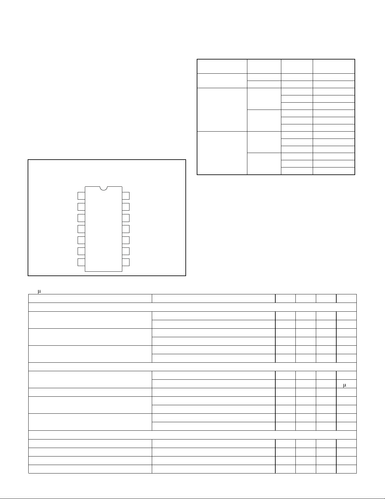
VREF
GND
SS
SYNC
CT
FB
VSCLAMP
1
2
3
4
5
6
7
14
13
12
11
10
9
8
ILIM
COUNT
VFF
RT
VDD
OUT
PGND
CONNECTION DIAGRAMS
DIL-14, SOIC-14,TSSOP-14 (TOP VIEW)
N or J, D, PW PACKAGE
ELECTRICAL CHARACTERISTICS: Unless otherwise specified, V
DD
= 11V, RT = 60.4k, C
T
= 330pF, C
REF
=C
VDD
=
0.1 F, V
FF
= 2.0V, and no load on the outputs.
PARAMETER TEST CONDITIONS MIN TYP MAX UNITS
UVLO Section
Start Threshold (UCCX5701) 12 13 14 V
(UCCX5702) 8.8 9.6 10.4 V
Stop Threshold (UCCX5701) 8 9 10 V
(UCCX5702) 8.0 8.8 9.6 V
Hysteresis (UCCX5701) 3 4 V
(UCCX5702) 0.3 0.8 V
Supply Current
Start-up Current (UCCX5701) V
DD
= 11V, V
DD
Comparator Off 130 200 µA
(UCCX5702) V
DD
= 8V, V
DD
Comparator Off 120 190 A
I
DD
Active V
DD
Comparator On 0.75 1.5 mA
V
DD
Clamp Voltage (UCCX5701) I
DD
= 10mA 13.5 14.3 15 V
(UCCX5702) I
DD
= 10mA 13 13.8 15 V
V
DD
Clamp – Start Threshold (UCCX5701) 1.3 V
(UCCX5702) 4.2 V
Voltage Reference
V
REF
V
DD
= 10V to 13V, I
VREF
= 0mA to 2mA 4.9 5 5.1 V
Line Regulation V
DD
= 10V to 13V 20 mV
Load Regulation I
VREF
= 0mA to 2mA 2 mV
Short Circuit Current V
REF
= 0V, TJ = 25°C 20 50 mA
T
A
=T
J
UVLO
Option
Package Part Number
–55°C to +125°C
13V / 9V CDIP-14 UCC15701J
9.6V / 8.8V CDIP-14 UCC15702J
–40°C to +85°C
13V / 9V
SOIC-14 UCC25701D
PDIP-14 UCC25701N
TSSOP-14 UCC25701PW
9.6V / 8.8V
SOIC-14 UCC25702D
PDIP-14 UCC25702N
TSSOP-14 UCC25702PW
0°C to +70°C
13V / 9V
SOIC-14 UCC35701D
PDIP-14 UCC35701N
TSSOP-14 UCC35701PW
9.6V / 8.8V
SOIC-14 UCC35702D
PDIP-14 UCC35702N
TSSOP-14 UCC35702PW
The D and PW packages are available taped and reeled. Add
TR suffix to the device type (e.g., UCC35701DTR).
ORDERING INFORMATION
3
UCC15701/2
UCC25701/2
UCC35701/2
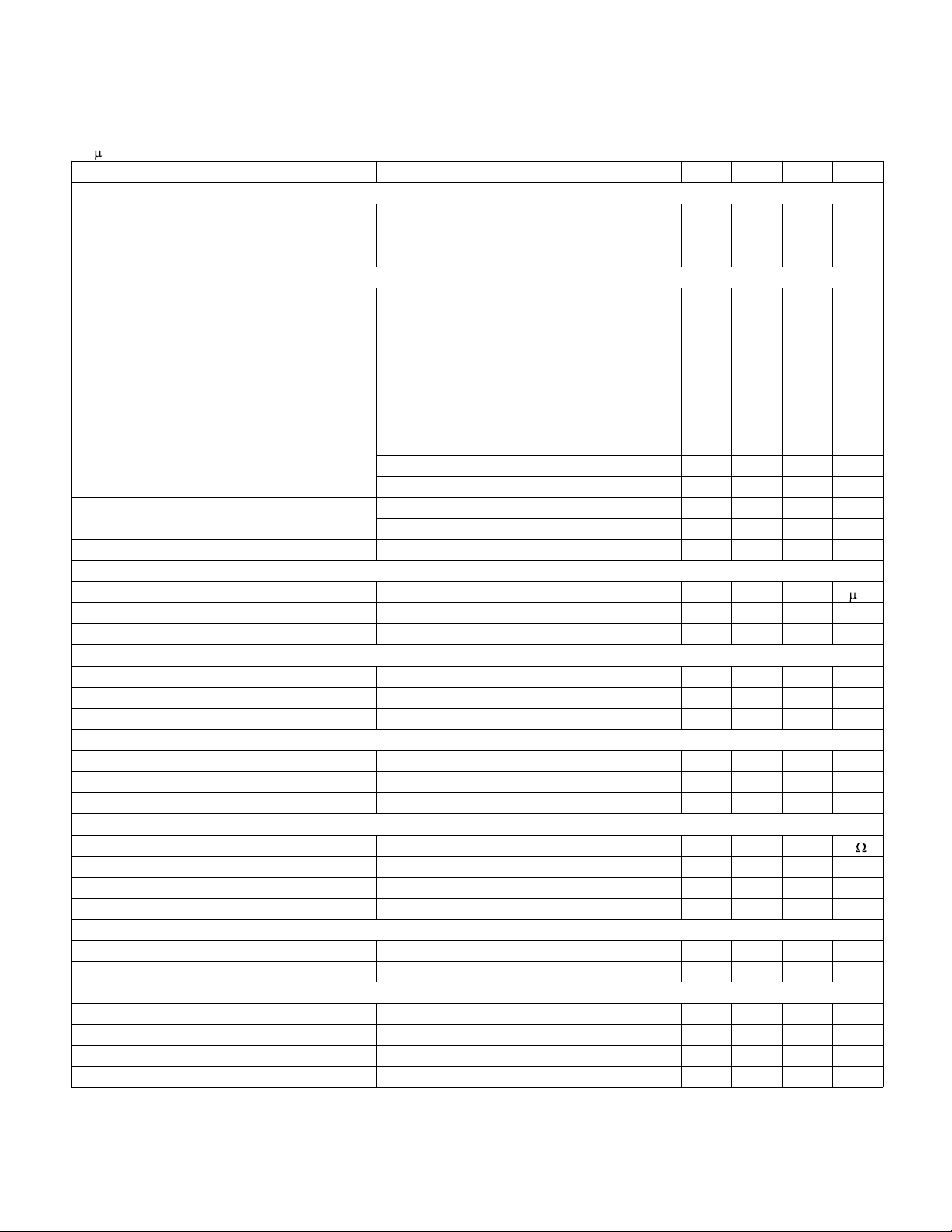
ELECTRICAL CHARACTERISTICS:
Unless otherwise specified, V
DD
= 11V, RT = 60.4k, C
T
= 330pF, C
REF
=C
VDD
=
0.1 F, V
FF
= 2.0V, and no load on the outputs.
PARAMETER TEST CONDITIONS MIN TYP MAX UNITS
Line Sense
Vth High Line Comparator 3.9 4 4.1 V
Vth Low Line Comparator 0.5 0.6 0.7 V
Input Bias Current –100 100 nA
Oscillator Section
Frequency V
FF
= 0.8V to 3.2V 90 100 110 kHz
Frequency V
FF
= 0.6V to 3.4V (Note 1) 90 100 110 kHz
SYNC VIH 2V
SYNC VIL 0.8 V
SYNC Input Current VSYNC = 2.0V 3 10 µA
RT Voltage VFF = 0.4V 0.5 0.6 0.7 V
VFF = 0.8V 0.75 0.8 0.85 V
VFF = 2.0V 1.95 2.0 2.05 V
VFF = 3.2V 3.15 3.2 3.25 V
VFF = 3.6V 3.3 3.4 3.5 V
C
T
Peak Voltage VFF = 0.8V (Note 1) 0.8 V
VFF = 3.2V (Note 1) 3.2 V
C
T
Valley Voltage (Note 1) 0 V
Soft Start/Shutdown/Duty Cycle Control Section
I
SS
Charging Current 10 18 30 A
I
SS
Discharging Current 300 500 750 µA
Saturation V
DD
= 11V, IC Off 25 100 mV
Fault Counter Section
Threshold Voltage VFF = 0.8V to 3.2V 3.8 4 4.2 V
Saturation Voltage VFF = 0.8V to 3.2V 100 mV
Count Charging Current 10 18 30 µA
Current Limit Section
Input Bias Current –100 0 100 nA
Current Limit Threshold 180 200 220 mV
Shutdown Threshold 500 600 700 mV
Pulse Width Modulator Section
FB Pin Input Impedance VFB = 3V 30 50 100 k
Minimum Duty Cycle VFB <= 1V 0 %
Maximum Duty Cycle VFB >= 4.5V, VSCLAMP >= 2.0V 95 99 100 %
PWM Gain VFF = 0.8V 35 50 70 %/V
Volt Second Clamp Section
Maximum Duty Cycle VFF = 0.8V, VSCLAMP = 0.6V 69 74 79 %
Minimum Duty Cycle VFF = 3.2V, VSCLAMP = 0.6V 17 19 21 %
Output Section
VOH I
OUT
= –100mA, (V
DD
–V
OUT
) 0.4 1 V
VOL I
OUT
= 100mA 0.4 1 V
Rise Time C
LOAD
= 1000pF 20 100 ns
Fall Time C
LOAD
= 1000pF 20 100 ns
Note 1: Guaranteed by design. Not 100% tested in production.
 Loading...