


 Loading...
Service and Parts Manual
For Models
• CO2075FF |
• 2075R |
• 2075WC |
• BI•2015 |
• 2075RF |
• 2015R |
• 2015WC |
• CLR2060 |
|
• Combo U-CO29FF |
|
|
U-Line Corporation |
U-Line Corporation |
8900 North 55th Street |
PO Box 245040 |
Milwaukee, WI 53223 |
Milwaukee, WI 53224-9540 |
www.U-LineService.com
Phone (414) 354-0300 • FAX (414) 354-7905
Service & Parts Tech Lines Phone (800) 779-2547 • FAX (414) 354-5696
M
A
DE
I
N
T
H
E
U
S
A
Design ■ Features ■ Performance
INTRODUCTION
INTRODUCTION
Three generations of pride and quality manufacturing and design improvements are built into all U-Line products. The result: U-Line leads the market with innovative technology and superior craftsmanship.
This manual contains specific instructions for servicing the U-Line Échelon Products which include these models:
• |
CO2075FF |
• |
2075R |
• |
2075WC |
• |
BI•2015 |
• |
2075RF |
• |
2015R |
• |
2015WC |
• |
CLR2060 Clear |
• |
Combo U-CO29FF |
|
|
|
|
|
Icemaker |
Potential Problems With HFC-134A
This Service Manual has been written to cover product manufactured with HFC-134a. HFC-134A compressors will be received with a synthetic based ester oil charge. The hygroscopic (water attraction) property of ester oil is many times greater than that of the mineral oils previously used with CFC-12. High system moisture causes the formation of acids and alcohol which can damage the compressor. Systems should not be left open for more than fifteen (15) minutes at any time as humidity from the air will enter system. To assure system dehydration, the system should be pulled down to 100 microns and vacuum pump oil (mineral oil) must not be allowed to enter the system.
Cleanliness of the system will be extremely important. The presence of residues (chlorinated or greasy residues, mineral oil, or impurities) can lead to capillary tube restrictions, oil return problems and compressor damage. Flux must not be used on brazed joints.
IMPORTANT
You can check for the latest service related information at U-LineService.com. The Technical Knowledge base is continuously updated and can be accessed 24/7.
INTRODUCTION
Design ■ Features ■ Performance
!
This is the safety alert symbol. It is used to alert you to potential personal injury hazards. Obey all safety messages that follow this symbol to avoid possible injury or death.
! DANGER !
DANGER indicates an imminently hazardous situation which, if not avoided, will result in death or serious injury.
! WARNING !
WARNING indicates a potentially hazardous situation which, if not avoided, could result in death or serious injury.
!
CAUTION indicates a potentially hazardous situation which, if not avoided, may result in minor or moderate injury.
CAUTION used without the safety alert symbol indicates a potentially hazardous situation which, if not avoided, may result in property damage.
IMPORTANT
IMPORTANT indicates installation, operation or maintenance information which is important but not hazard-related.
2

Design ■ Features ■ Performance
INTRODUCTION
TABLE OF CONTENTS |
|
General Information . . . . . . . . . . . . . . . . . . . . . . . . . . . . . . . . . . . . . . . . . . . . . . . . . . . . . . . . . . . . . |
. 5 |
Serial Number Format . . . . . . . . . . . . . . . . . . . . . . . . . . . . . . . . . . . . . . . . . . . . . . . . . . . . . . . . . . |
.5 |
Limited Warranty . . . . . . . . . . . . . . . . . . . . . . . . . . . . . . . . . . . . . . . . . . . . . . . . . . . . . . . . . . . . . |
.6 |
Warranty Claims Procedure . . . . . . . . . . . . . . . . . . . . . . . . . . . . . . . . . . . . . . . . . . . . . . . . . . . . . . |
.7 |
Proof of Purchase . . . . . . . . . . . . . . . . . . . . . . . . . . . . . . . . . . . . . . . . . . . . . . . . . . . . . . . . . . . . . |
.8 |
Parts Listing . . . . . . . . . . . . . . . . . . . . . . . . . . . . . . . . . . . . . . . . . . . . . . . . . . . . . . . . . . . . . . . . . |
.9 |
Safety Precautions . . . . . . . . . . . . . . . . . . . . . . . . . . . . . . . . . . . . . . . . . . . . . . . . . . . . . . . . . . . . . |
10 |
Échelon™ Door Adjustment . . . . . . . . . . . . . . . . . . . . . . . . . . . . . . . . . . . . . . . . . . . . . . . . . . . . . |
11 |
Screening Calls . . . . . . . . . . . . . . . . . . . . . . . . . . . . . . . . . . . . . . . . . . . . . . . . . . . . . . . . . . . . . . . . .13
Guide For Screening Calls . . . . . . . . . . . . . . . . . . . . . . . . . . . . . . . . . . . . . . . . . . . . . . . . . . . . . . .13
CO2075FF/2075RF/Origins Combo U-CO29FF Models . . . . . . . . . . . . . . . . . . . . . . . . . . . . . . . . . . . .17
Compressor/Electrical Specifications . . . . . . . . . . . . . . . . . . . . . . . . . . . . . . . . . . . . . . . . . . . . . . .17
Compressor Pins . . . . . . . . . . . . . . . . . . . . . . . . . . . . . . . . . . . . . . . . . . . . . . . . . . . . . . . . . . . . . .17
U-Line Frost Free Refrigeration System . . . . . . . . . . . . . . . . . . . . . . . . . . . . . . . . . . . . . . . . . . . . . .18
Typical Frost Free Airflow Configuration . . . . . . . . . . . . . . . . . . . . . . . . . . . . . . . . . . . . . . . . . . . . .19
Refrigeration System Diagnosis Guide . . . . . . . . . . . . . . . . . . . . . . . . . . . . . . . . . . . . . . . . . . . . . .20
CO2075FF and U-CO29FF Ice Maker Operation . . . . . . . . . . . . . . . . . . . . . . . . . . . . . . . . . . . . . .21
Ice Maker Diagnosis Flow Chart . . . . . . . . . . . . . . . . . . . . . . . . . . . . . . . . . . . . . . . . . . . . . . . . . .22
Troubleshooting . . . . . . . . . . . . . . . . . . . . . . . . . . . . . . . . . . . . . . . . . . . . . . . . . . . . . . . . . . . . . .23
Disassembly Procedures . . . . . . . . . . . . . . . . . . . . . . . . . . . . . . . . . . . . . . . . . . . . . . . . . . . . . . . .26
Replacing Ice Maker Assembly . . . . . . . . . . . . . . . . . . . . . . . . . . . . . . . . . . . . . . . . . . . . . . . . . . .27
Replacing Mold and Heater . . . . . . . . . . . . . . . . . . . . . . . . . . . . . . . . . . . . . . . . . . . . . . . . . . . . . .28
CO2075FF Wiring Diagram . . . . . . . . . . . . . . . . . . . . . . . . . . . . . . . . . . . . . . . . . . . . . . . . . . . . . .29
U-CO29FF Wiring Diagram . . . . . . . . . . . . . . . . . . . . . . . . . . . . . . . . . . . . . . . . . . . . . . . . . . . . . .29
2075RF Wiring Diagram . . . . . . . . . . . . . . . . . . . . . . . . . . . . . . . . . . . . . . . . . . . . . . . . . . . . . . . .30
CO2075FF Parts List . . . . . . . . . . . . . . . . . . . . . . . . . . . . . . . . . . . . . . . . . . . . . . . . . . . . . . . . . . .33
Model 402-CO2075FF Icemaker Parts List . . . . . . . . . . . . . . . . . . . . . . . . . . . . . . . . . . . . . . . . . . .37
Model U-CO29FF – 2002 Design Parts List . . . . . . . . . . . . . . . . . . . . . . . . . . . . . . . . . . . . . . . . . .39
Model U-CO29FF & Icemaker . . . . . . . . . . . . . . . . . . . . . . . . . . . . . . . . . . . . . . . . . . . . . . . . . . . .42
Model 402-CO29FF Parts List . . . . . . . . . . . . . . . . . . . . . . . . . . . . . . . . . . . . . . . . . . . . . . . . . . . .43
Model 2075RF Parts List . . . . . . . . . . . . . . . . . . . . . . . . . . . . . . . . . . . . . . . . . . . . . . . . . . . . . . . .45
2075R/2015R Models . . . . . . . . . . . . . . . . . . . . . . . . . . . . . . . . . . . . . . . . . . . . . . . . . . . . . . . . . . . . .49
Compressor/Electrical Specifications . . . . . . . . . . . . . . . . . . . . . . . . . . . . . . . . . . . . . . . . . . . . . . .49
Compressor Pins . . . . . . . . . . . . . . . . . . . . . . . . . . . . . . . . . . . . . . . . . . . . . . . . . . . . . . . . . . . . . .49
Refrigeration System . . . . . . . . . . . . . . . . . . . . . . . . . . . . . . . . . . . . . . . . . . . . . . . . . . . . . . . . . . .50
Refrigeration System Diagnosis Guide . . . . . . . . . . . . . . . . . . . . . . . . . . . . . . . . . . . . . . . . . . . . . .51
Troubleshooting . . . . . . . . . . . . . . . . . . . . . . . . . . . . . . . . . . . . . . . . . . . . . . . . . . . . . . . . . . . . . .52
2075R/2015R Wiring Diagram . . . . . . . . . . . . . . . . . . . . . . . . . . . . . . . . . . . . . . . . . . . . . . . . . . . .53
2075R Parts List . . . . . . . . . . . . . . . . . . . . . . . . . . . . . . . . . . . . . . . . . . . . . . . . . . . . . . . . . . . . . .55
2015R Parts List . . . . . . . . . . . . . . . . . . . . . . . . . . . . . . . . . . . . . . . . . . . . . . . . . . . . . . . . . . . . . .57
3
INTRODUCTION
Design ■ Features ■ Performance
2075WC/2015WC Models . . . . . . . . . . . . . . . . . . . . . . . . . . . . . . . . . . . . . . . . . . . . . . . . . . . . . . . . .59 Compressor/Electrical Specifications . . . . . . . . . . . . . . . . . . . . . . . . . . . . . . . . . . . . . . . . . . . . . . .59 Compressor Pins . . . . . . . . . . . . . . . . . . . . . . . . . . . . . . . . . . . . . . . . . . . . . . . . . . . . . . . . . . . . . .59 Refrigeration System . . . . . . . . . . . . . . . . . . . . . . . . . . . . . . . . . . . . . . . . . . . . . . . . . . . . . . . . . . .60 Refrigeration System Diagnosis Guide . . . . . . . . . . . . . . . . . . . . . . . . . . . . . . . . . . . . . . . . . . . . . .61 Troubleshooting . . . . . . . . . . . . . . . . . . . . . . . . . . . . . . . . . . . . . . . . . . . . . . . . . . . . . . . . . . . . . .62 2075WC/2015WC Wiring Diagram . . . . . . . . . . . . . . . . . . . . . . . . . . . . . . . . . . . . . . . . . . . . . . . .63 2075WC Parts List . . . . . . . . . . . . . . . . . . . . . . . . . . . . . . . . . . . . . . . . . . . . . . . . . . . . . . . . . . . .65 2015WC Parts List . . . . . . . . . . . . . . . . . . . . . . . . . . . . . . . . . . . . . . . . . . . . . . . . . . . . . . . . . . . .67
BI•2015 Model . . . . . . . . . . . . . . . . . . . . . . . . . . . . . . . . . . . . . . . . . . . . . . . . . . . . . . . . . . . . . . . . .69
Compressor/Electrical Specifications . . . . . . . . . . . . . . . . . . . . . . . . . . . . . . . . . . . . . . . . . . . . . . .69
Compressor Pins . . . . . . . . . . . . . . . . . . . . . . . . . . . . . . . . . . . . . . . . . . . . . . . . . . . . . . . . . . . . . .69
Temperature Control Specifications . . . . . . . . . . . . . . . . . . . . . . . . . . . . . . . . . . . . . . . . . . . . . . . .70
Limit Switch Specifications . . . . . . . . . . . . . . . . . . . . . . . . . . . . . . . . . . . . . . . . . . . . . . . . . . . . . .71
Refrigeration System-Normal Vapor . . . . . . . . . . . . . . . . . . . . . . . . . . . . . . . . . . . . . . . . . . . . . . . .72
Refrigeration System Diagnosis Guide . . . . . . . . . . . . . . . . . . . . . . . . . . . . . . . . . . . . . . . . . . . . . .73
Ice Maker Diagnosis Flow Chart . . . . . . . . . . . . . . . . . . . . . . . . . . . . . . . . . . . . . . . . . . . . . . . . . .74
Ice Maker Operating Cycles . . . . . . . . . . . . . . . . . . . . . . . . . . . . . . . . . . . . . . . . . . . . . . . . . . . . .75
BI•2015 Cycle Schematics . . . . . . . . . . . . . . . . . . . . . . . . . . . . . . . . . . . . . . . . . . . . . . . . . . . . . .76
BI•2015 Replacing Ice Maker Assembly . . . . . . . . . . . . . . . . . . . . . . . . . . . . . . . . . . . . . . . . . . . . .78
BI•2015 Replacing Mold and Heater . . . . . . . . . . . . . . . . . . . . . . . . . . . . . . . . . . . . . . . . . . . . . . .79
Troubleshooting . . . . . . . . . . . . . . . . . . . . . . . . . . . . . . . . . . . . . . . . . . . . . . . . . . . . . . . . . . . . . .80
BI•2015 Wiring Diagram . . . . . . . . . . . . . . . . . . . . . . . . . . . . . . . . . . . . . . . . . . . . . . . . . . . . . . . .82
BI•2015 Parts List . . . . . . . . . . . . . . . . . . . . . . . . . . . . . . . . . . . . . . . . . . . . . . . . . . . . . . . . . . . . .85
Model 402-BI•2015 Ice Maker Parts List . . . . . . . . . . . . . . . . . . . . . . . . . . . . . . . . . . . . . . . . . . . .87
CLR2060 Model . . . . . . . . . . . . . . . . . . . . . . . . . . . . . . . . . . . . . . . . . . . . . . . . . . . . . . . . . . . . . . . . .89
Electrical Specifications . . . . . . . . . . . . . . . . . . . . . . . . . . . . . . . . . . . . . . . . . . . . . . . . . . . . . . . . .89
Compressor Pins . . . . . . . . . . . . . . . . . . . . . . . . . . . . . . . . . . . . . . . . . . . . . . . . . . . . . . . . . . . . . .89
Leveling and Installation Requirements . . . . . . . . . . . . . . . . . . . . . . . . . . . . . . . . . . . . . . . . . . . . .90
Gravity Drain Installation . . . . . . . . . . . . . . . . . . . . . . . . . . . . . . . . . . . . . . . . . . . . . . . . . . . . . . .91
Connecting a Drain Pump . . . . . . . . . . . . . . . . . . . . . . . . . . . . . . . . . . . . . . . . . . . . . . . . . . . . . . .92
Automatic Clean Cycle Instructions . . . . . . . . . . . . . . . . . . . . . . . . . . . . . . . . . . . . . . . . . . . . . . . .93
Sequence of Operation . . . . . . . . . . . . . . . . . . . . . . . . . . . . . . . . . . . . . . . . . . . . . . . . . . . . . . . . .94
Thermistor . . . . . . . . . . . . . . . . . . . . . . . . . . . . . . . . . . . . . . . . . . . . . . . . . . . . . . . . . . . . . . . . . .96
New CLR2060 Control Board Design . . . . . . . . . . . . . . . . . . . . . . . . . . . . . . . . . . . . . . . . . . . . . . .97
Low Side Pressure Changes . . . . . . . . . . . . . . . . . . . . . . . . . . . . . . . . . . . . . . . . . . . . . . . . . . . . . .99
Refrigeration System Diagnostic Guide . . . . . . . . . . . . . . . . . . . . . . . . . . . . . . . . . . . . . . . . . . . . .100
Ice Thickness Adjustment . . . . . . . . . . . . . . . . . . . . . . . . . . . . . . . . . . . . . . . . . . . . . . . . . . . . . .101
Ice Production Rates . . . . . . . . . . . . . . . . . . . . . . . . . . . . . . . . . . . . . . . . . . . . . . . . . . . . . . . . . .104
Troubleshooting . . . . . . . . . . . . . . . . . . . . . . . . . . . . . . . . . . . . . . . . . . . . . . . . . . . . . . . . . . . . .105
CLR2060 Wiring Diagram . . . . . . . . . . . . . . . . . . . . . . . . . . . . . . . . . . . . . . . . . . . . . . . . . . . . . .109
CLR2060 Parts List . . . . . . . . . . . . . . . . . . . . . . . . . . . . . . . . . . . . . . . . . . . . . . . . . . . . . . . . . . . .111
4
Design ■ Features ■ Performance
GENERAL INFORMATION
SERIAL NUMBER FORMAT
The serial number is divided into four segments. A typical serial number is 013520-03-0433. The first two digits of the first segment, 01, represents the year the unit was made.
The next four digits of the first segment, 3520, represents the shop order number. Order number 3520 is assigned for the Model 75R White-00 units.
The second two digit segment, 03, represents the month the unit was made.
The third four digit segment, XXXX, is a factory internal control number used at U-Line Corporation.
013520-03-XXXX
Year Shop Month |
Factory Internal |
Order |
Control Number |
Number |
|
5

GENERAL INFORMATION
Design ■ Features ■ Performance
LIMITED WARRANTY
U-Line Corporation warrants each U-Line product to be free from defects in materials and workmanship for a period of one year from the date of purchase; and warrants the sealed system (consisting of the compressor, the condenser, the evaporator, the hot gas bypass valve, the dryer and the connecting tubing) in each U-Line product to be free from defects in materials and workmanship for a period of five years from the date of purchase. During the initial one-year warranty period for all U-Line products U-Line shall: (1) at U-Line’s option, repair any product or replace any part of a product that breaches this warranty; and (2) for all Marine, RV and Domestic U-Line products sold and serviced in the United States (including Alaska and Hawaii) and Canada, U-Line shall cover the labor costs incurred in connection with the replacement of any defective part. During years two through five of the warranty period for the sealed system, U-Line shall: (1) repair or replace any part of the sealed system that breaches this warranty; and (2) for all Marine, RV and Domestic U-Line products sold and serviced in the United States (including Alaska and Hawaii) and Canada, U-Line shall cover the labor costs incurred in connection with the replacement of any defective part of the sealed system. All other charges, including transportation charges for replacements under this warranty and labor costs not specifically covered by this warranty, shall be borne by you. This warranty is extended only to the original purchaser of the U-Line product. The Product Registration Card included with the product should be promptly completed by you and mailed back to U-Line or you can register on-line at www.U-LineService.com.
The following are excluded from this limited warranty: installation charges; damages caused by disasters or acts of God, such as fire, floods, wind and lightening; damages incurred or resulting from shipping, improper installation, unauthorized modification, or misuse/abuse of the product; customer education calls; food loss/spoilage; door and water level adjustments (except during the first 90 days from the date of purchase); defrosting the product; adjusting the controls; door reversal; or cleaning the condenser.
If a product defect is discovered during the applicable warranty period, you must promptly notify either the dealer from whom you purchased the product or U-Line at P.O. Box 23220, Milwaukee, Wisconsin 53223 or at 414-354-0300. In no event shall such notification be received later than 30 days after the expiration of the applicable warranty period. U-Line may require that defective parts be returned, at your expense, to U-Line’s factory in Milwaukee, Wisconsin, for inspection. Any action by you for breach of warranty must be commenced within one year after the expiration of the applicable warranty period.
This limited warranty is in lieu of any other warranty, express or implied, including, but not limited to any implied warranty of merchantability or fitness for a particular purpose; provided however, that to the extent required by law, implied warranties are included but do not extend beyond the duration of the express warranty first set forth above. U-Line’s sole liability and your exclusive remedy under this warranty is set forth in the initial paragraph above. U-Line shall have no liability whatsoever for any incidental, consequential or special damages arising from the sale, use or installation of the product or from any other cause whatsoever, whether based on warranty (express or implied) or otherwise based on contract, tort or any other theory of liability.
Some states do not allow limitations on how long an implied warranty lasts or the exclusion or limitation of incidental or consequential damages, so the above limitations may not apply to you. This warranty gives you specific legal rights, and you may also have other rights which vary from state to state.
6

Design ■ Features ■ Performance
GENERAL INFORMATION
WARRANTY CLAIMS PROCEDURE
When submitting claims for warranty payment, please follow these guidelines.
You can use any form you would normally use to bill your customer (your own computer generated form, Narda, USA, etc.).
The model and serial number MUST be on the claims. Claims will not be paid without a model and serial number.
If you work on more than one unit per service call please submit a separate claim for each unit.
We track all defects through warranty claims, so please be specific on what the repair was. If it is a system leak, please specify where the leak was.
Please be sure the claim is legible. If the claim form cannot be read, it will be returned, unpaid.
U-Line will not cover part or labor claims for the replacement of a complete ice maker assembly. All ice maker parts are available as replacement parts and are stocked in our inventory. Remember: we do not pay customer education calls. Door and water level adjustments are 90 day warranties only.
If you are changing out a unit please supply the model and serial number of both units (the unit being replaced and the new unit) and the R.A. number.
Occasionally the customer does not return their warranty cards. In this case we use the date the unit was shipped to our distributor for a beginning warranty date. This may cause the claim to be rejected for a proof of purchase. If you want to check on a purchase date, you may contact the U-Line Corporation Customer Assurance Department at 1-800-779-2547. This will allow you to get a proof of purchase, if needed, before you submit the claim.
At U-Line, parts and labor claims are paid separately. Included in labor are freon and recovery charges, all other parts are handled by the parts department. We require that some parts be returned to us, so we may return them to our vendor. It will be noted on your packing list if we require you to return the part. If a part is to be returned please include a copy of the packing list and a copy of your claim. If the part was purchased at one of our part distributors, you must handle the part warranty with that company. For labor payment please send a readable copy of your claim to U-Line Corporation, P.O. Box 245040, Milwaukee WI, 53224-9540, for warranty payment.
7

GENERAL INFORMATION
Design ■ Features ■ Performance
PROOF OF PURCHASE
Proof of Purchase and/or Proof of Install is an important part of the warranty claim process. Sometimes it is difficult to obtain a proper Proof of Purchase/Install for a number of different reasons:
•The customer does not have a copy (only the original).
•The customer has only their copy of the final Walk Through or sign-off of new construction.
•Other valid reasons that prevent your technician from leaving the job site with a suitable Proof of Purchase/Install.
We understand the problem and have modified our Proof of Purchase policy to help you in these situations. Effective immediately, if a copy of the Proof of Purchase/Install is not available at the site, the technician should record the following information on the Labor Invoice:
•The name of the selling Dealer
•The date of purchase/installation
•The Order or Invoice number (if available)
•The type of document they saw, i.e. Store Receipt, Closing Papers, Sign-Off of Building Permit, Final Walk Through, etc.
If we have this information on the Labor Invoice, and we have the other information that is needed
(correct Serial Number, type of repair, time spent on repairs, etc.), we will be able to process the invoice for you in a timely manner.
8

Design ■ Features ■ Performance
GENERAL INFORMATION
PARTS LISTING
How to Order Replacement Parts
1.Locate the illustration(s) for the model you are servicing.
2.Refer to the area where the desired part would be installed, locate the part and note the item number assigned to it.
3.Locate the item number in the left column of the parts listing which is on the next page from the product illustration. Note the full description and the corresponding part number. If this is for a warranty unit, please indicate and record the model and serial numbers.
4.When ordering parts, it will be necessary to supply us with Model Number, Serial Number, Part Number, Part Description and in some cases Color or Voltage.
5.U-Line requires the return of the parts listed below if replaced under warranty.
•Fan motors (condenser and evaporator)
•Temperature controls
•Water solenoid valves
•Pumps
•Control boards
•Ice maker motors
•Bypass solenoids
•Compressors (two years old or less - lines soldered closed)
All warranty parts will be shipped at no charge as long as warranty status has been confirmed. We require that some parts be returned to us, so we may return them to our vendor. It will be noted on your packing list if we require you to return a part or if you may field scrap it. If U-Line requires a defective part to be returned, a prepaid shipping label will be included with your new replacement part. When returning parts please enclose a copy of your packing list and a copy of your labor claim, showing the model and serial number, and tag or label the part with the nature of the defect.
Our warranty records may not match the customer’s information. In this case a proof of purchase will be required. If you do not have the proof of purchase at the time the order is placed, the part will be sent net 15 days (COD if you don’t have an open account with U-Line Corporation). When the proof of purchase is provided we will credit your account (a check will be sent if the part was sent COD).
6. Parts may be ordered by FAX, phone or on-line:
FAX Number (414) 354-7905
Phone Number (414) 354-0300 or (414) 354-7885; press 3
www.U-LineService.com
To expedite parts shipments, FAX all parts orders to: (414) 354-7905. Copy the FAX Parts Order Form, located in the back of this manual, when placing an order.
7.Effective immediately, U-Line will not pay warranty claims for the replacement of a complete ice maker assembly. Complete ice maker assembly replacement is not necessary because all ice maker parts are available as replacement parts and are stocked in our inventory.
REPLACEMENT PARTS: Use only genuine U-Line replacement parts. The use of non-U-Line parts can reduce ice rate, cause water to overflow from ice maker mold, damage the unit, and may void the warranty.
9
GENERAL INFORMATION
Design ■ Features ■ Performance
SAFETY PRECAUTIONS
Do not attempt to service or repair the unit until you have read the entire procedure. Safety items throughout this manual are labeled with Danger, Warning or Caution.
! DANGER !
Risk of child entrapment. Before you throw away an old refrigerator or freezer: Take off the doors, leave shelves in place so that children may not easily climb inside.
!DANGER !
•Never attempt to repair or perform maintenance on the unit until the electricity has been disconnected.
•Altering, cutting of power cord, removal of power cord, removal of power plug, or direct wiring can cause serious injury, fire and/or loss of property and/or life and will void the warranty.
•Do not lift unit by door handle.
•Never use an ice pick or other sharp instrument to help speed up defrosting. These instruments can puncture the inner lining or damage the cooling unit.
•Failure to clean the condenser every three months can cause the unit to malfunction. This could void the warranty.
•Never install the unit behind closed doors. Be sure front grille is free of obstruction. Obstructing free air flow can cause the unit to malfunction, and may void the warranty.
10
Design ■ Features ■ Performance
GENERAL INFORMATION
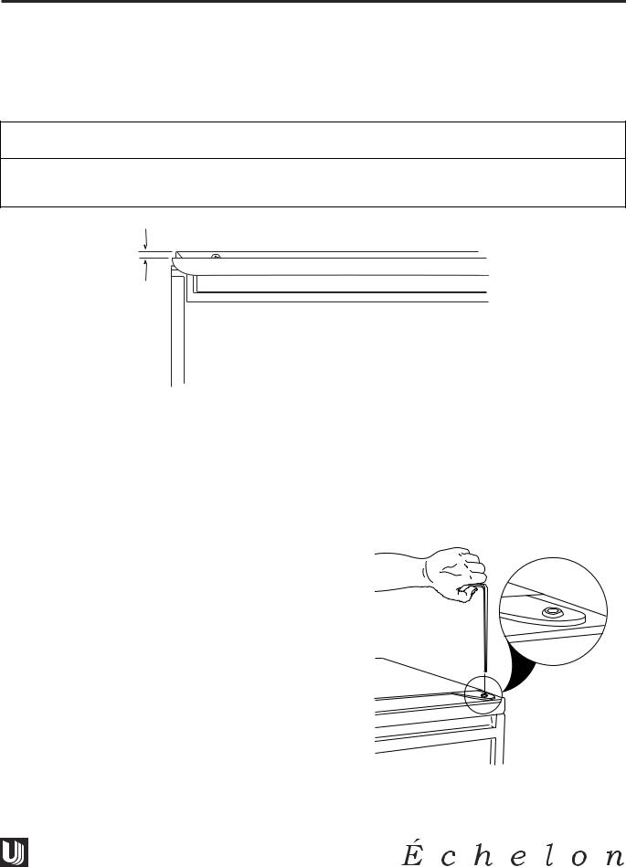
ÉCHELON™ DOOR ADJUSTMENT
All Échelon™ model doors are aligned at the factory before shipment. Occasional re-adjustment may be necessary, especially if an Overlay Panel is installed. The following procedure will correct for up to 1/4" alignment.
IMPORTANT
The door should never be flush with the top of the cabinet. Even when level, the top edge of the door will be 1/8" below the top of the cabinet (see Figure 1).
1/8"
DOOR001
Figure 1
To adjust door:
1.Compare the top edge of the door (opposite the hinges) to the top edge of the cabinet and note the type (up or down) of adjustment needed.
2.Remove the top hinge pivot pin with a 7/64" hex wrench (see Figure 2) and lift door off bottom hinge pin. Be careful not to lose door closer inserts (see Figure 5).
Note: The hinge plate on some Échelon™ models does not have the holes slotted for adjustment. New hinge plates are available from U-Line Customer Service.
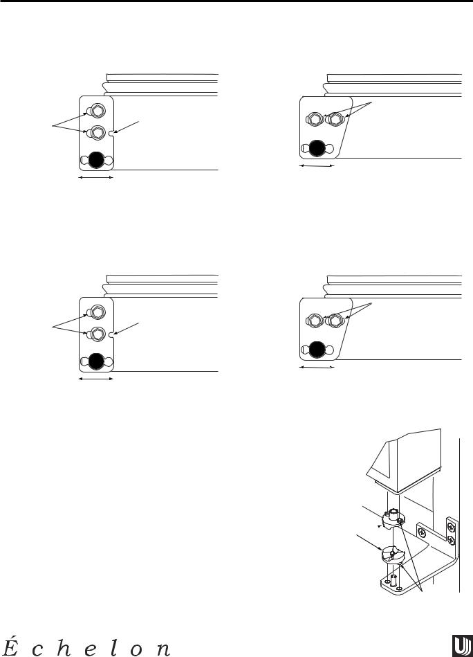
3. With door upside-down, inspect the bottom hinge plate mounting holes.
a.If your plate has slotted mounting holes, loosen but do not remove the two hinge plate screws.
b.If your plate does not have slotted mounting
holes, remove the old plate and install the new plate with the notch to the inside of the door (see Figure 3).
UL310
Figure 2
11
GENERAL INFORMATION
Design ■ Features ■ Performance
4.If door edge opposite the hinges needs to move up, move plate toward outside of door. If door edge needs to move down, move plate toward inside of door (see Figure 3). Repeat until top edge of door is parallel with top of cabinet and tighten screws securely.
|
|
|
SLOTTED |
|
SLOTTED |
|
|
MOUNTING |
|
NOTCH |
|
HOLES |
||
MOUNTING |
|
|
|
|
HOLES |
|
|
ALL WINE |
|
|
ALL MODELS |
|
||
|
|
CAPTAIN MODELS |
||
|
EXCEPT WINE CAPTAIN |
|
|
|
|
|
RAISE |
LOWER |
|
RAISE |
LOWER |
OUTSIDE |
OUTSIDE |
|
DOOR EDGE |
DOOR EDGE |
|||
OUTSIDE |
OUTSIDE |
|||
|
|
|||
DOOR EDGE |
DOOR EDGE |
|
|
DOOR003
Figure 3
5.If you have an older model, you must slot the door frame to accommodate the door closer boss. Using the bottom hinge plate pivot hole as a guide, slot the frame hole by using an 11/32" drill.
|
|
|
SLOTTED |
|
SLOTTED |
|
|
MOUNTING |
|
NOTCH |
|
HOLES |
||
MOUNTING |
|
|
|
|
HOLES |
|
|
ALL WINE |
|
|
ALL MODELS |
|
||
|
|
CAPTAIN MODELS |
||
|
EXCEPT WINE CAPTAIN |
|
|
|
|
|
RAISE |
LOWER |
|
RAISE |
LOWER |
OUTSIDE |
OUTSIDE |
|
DOOR EDGE |
DOOR EDGE |
|||
OUTSIDE |
OUTSIDE |
|||
|
|
|||
DOOR EDGE |
DOOR EDGE |
|
|
DOOR003
Figure 4
6.After adjustment is complete, remove the door closers from the bottom hinge, clean thoroughly and apply petroleum jelly to the mating surfaces of the closers (see Figure 5). Be sure that bosses on closers align with holes in hinge and hinge plate. Mount door and install top hinge pivot pin.
DOOR 
CLOSER
INSERTS
BOSS
UL312
Figure 5
12

Design ■ Features ■ Performance
SCREENING CALLS
GUIDE FOR SCREENING CALLS
U-line’s warranty does not cover customer education calls. It has been reported that as high as 50% of all service calls performed are customer education calls.
The following guide has been developed to help screen calls on the most common customer education issues. It can be used by persons scheduling service calls. Questions to ask before scheduling a service call:
CUSTOMER
COMPLAINT The unit is not cold enough!
•Are you familiar with the factory specifications for this unit? (Many factors can cause these figures to vary: ambient temperature, application, amount of use, etc.)
Model Numbers |
Approximate Temperatures |
2075WC, 2015WC |
60° top rack /55° middle/ 45° bottom |
2075R, 2015R |
38° |
2075RF |
38° fresh food, 0° freezer |
CO2075FF, U-CO29FF |
38° fresh food |
•Is the door sealing properly? If the door is not sealed properly, it allows heat into the unit. U-Line’s warranty is 90 days for door adjustments.
•Is the condenser clean? U-Line’s warranty does not cover cleaning the condenser.
•Is the unit behind closed doors? The unit must have free air flow to the front grille.
•Did you try turning the temperature control colder? Turning the control knob clockwise is colder. Be sure to allow 24 hours between temperature control adjustments.
•For Wine Captain Units Only - Is the light on constantly to display the wine? If the light is on constantly, this could cause the unit to run warmer.
CUSTOMER
COMPLAINT The unit is frosting up!
•Are you familiar with the defrost technology of the unit?
Defrost Technology |
Model Numbers |
Manual Defrost |
BI•2015 |
Cycle Defrost |
2075R, 2015R, 2075WC, 2015WC |
Frost Free |
CO2075FF, 2075RF, U-CO29FF |
•Is the door sealing properly? U-Line's warranty is 90 days for door adjustments.
•Has the door been left open?
•Is the unit in an application of heavy usage? Heavy usage or high ambient temperatures will cause a unit to frost up.
CUSTOMER
COMPLAINT The light on my Wine Captain never shuts off!
•Did you turn the ON/OFF switch near the base of the unit? The ON/OFF switch is for the light operation only. When the switch is in the OFF position, the light will turn on only when the door is open. When the switch is in the ON position, the light will be on constantly to display the wine. To shut the unit OFF, turn the temperature control all the way counterclockwise.
13
SCREENING CALLS
Design ■ Features ■ Performance
CUSTOMER The ice cubes are sticking together! - U-CO29FF, CO2075FF and BI•2015 COMPLAINT Models Only
•BI•2015 Model Only - Does the unit need to be defrosted?
•Is the door sealing properly? This could cause the ice cubes to stick together.
•Have you tried to shake the ice bucket? If the ice sits without being used, it will tend to stick together. Shaking the bucket will usually break apart the ice cubes. If the ice has been sitting for a long time, we recommend dumping the bucket and making fresh ice.
•CO2075FF, U-CO29FF - Turn freezer control colder.
CUSTOMER Water is leaking out of the unit! - U-CO29FF, CO2075FF and BI•2015 COMPLAINT Models Only
•Have you checked the connection at the water solenoid valve? U-Line’s warranty does not cover installation adjustments.
CUSTOMER No ice or not enough ice! - U-CO29FF, CO2075FF, BI•2015 and CLR2060 COMPLAINT Models Only
•Are you aware of the factory specifications for ice production?
Model # |
Approx. Daily Ice Rate |
Approx. Ice Storage |
CO2075FF, U-CO29FF |
8 lbs. |
13 lbs. bucket |
CLR2060 |
60 lbs. |
35 lbs. bucket |
BI•2015 |
25 lbs. |
25 lbs. bucket |
•Is the ice maker bin arm down? When the arm is up, it will not make ice.
•Is the door sealing properly? U-Line’s warranty is 90 days for door adjustments.
•Does the water level need to be adjusted? U-Line’s warranty is 90 days for water level adjustments.
•BI•2015 Model Only - Is the temperature control set to the warmest setting? The unit will produce the most ice when set at the warmest setting. Let the unit run overnight.
•CO2075FF, U-CO29FF - Turn freezer control colder.
CUSTOMER
COMPLAINT My cubes are wet - CLR2060 Model Only
•The storage bin that holds the ice is not refrigerated. The cubes in the bin are slowly melting down. The bin will maintain a temperature of 32 to 34 degrees.
CUSTOMER
COMPLAINT The floor is very warm in front of my CLR2060 Model
•The unit is designed for a built-in application, so the warm air will discharge out the bottom of the unit below the door. There is a safety feature built into the control board that will shut the unit down if the warm air cannot be dissipated.
CUSTOMER No ice, water pours into the trough and down into the drain - CLR2060
COMPLAINT Model Only
•The standpipe needs to be inserted into the drain hole of the water trough to maintain the proper level of water inside the trough.
14

Design ■ Features ■ Performance
SCREENING CALLS
CUSTOMER
COMPLAINT When I turn the unit on, all I get is water fill - CLR2060 Model Only
•Check to be sure switch is in ice mode.
•Once the unit is turned on, there will be a three minute water fill. This will assure that a fresh batch of water has filled the trough. If water flows more than three minutes a service call will be required.
CUSTOMER
COMPLAINT My ice does not come out in a perfect cube shape - CLR2060 Model Only
•The manner in which the ice is made causes a small hole or “dimple” to appear on the front or top of the cube. Increasing or decreasing the time of the freeze cycle will adjust the size of the dimple. A service company will need to make this adjustment.
CUSTOMER
COMPLAINT The cubes do not fall into bin as individual cubes - CLR2060 Model Only
•Normal - You can use the scoop to break apart.
CUSTOMER
COMPLAINT Not enough ice is stored in the bin - CLR2060 Model Only
•Check the level of the unit.
15
SCREENING CALLS
Design ■ Features ■ Performance
NOTES
16
Design ■ Features ■ Performance
CO2075FF/2075RF & U-CO29FF MODELS
COMPRESSOR/ELECTRICAL SPECIFICATIONS
OVERLOAD PROTECTOR
STARTING RELAY
C
S R
RELAY COVER |
CAPACITOR |
UL183-3.1
COMPRESSOR PINS
To measure start winding resistance, measure across the C-S pins.
To measure run winding resistance, measure across the C-R pins. Ensure that pins C and R are not shorted to ground.
Specifications |
|
|
EMU45HSC Start Winding Resistance: |
5.60 OHMS |
|
EMU45HSC Run Winding Resistance: |
6.70 OHMS |
|
115 |
VOLT Ice Maker Heater Resistance: |
80 OHMS |
115 |
VOLT Water Valve Coil Resistance: |
335 OHMS |
115 |
VOLT Drain Pan Heater |
630-661 OHMS |
17
CO2075FF/2075RF & U-CO29FF MODELS
Design ■ Features ■ Performance
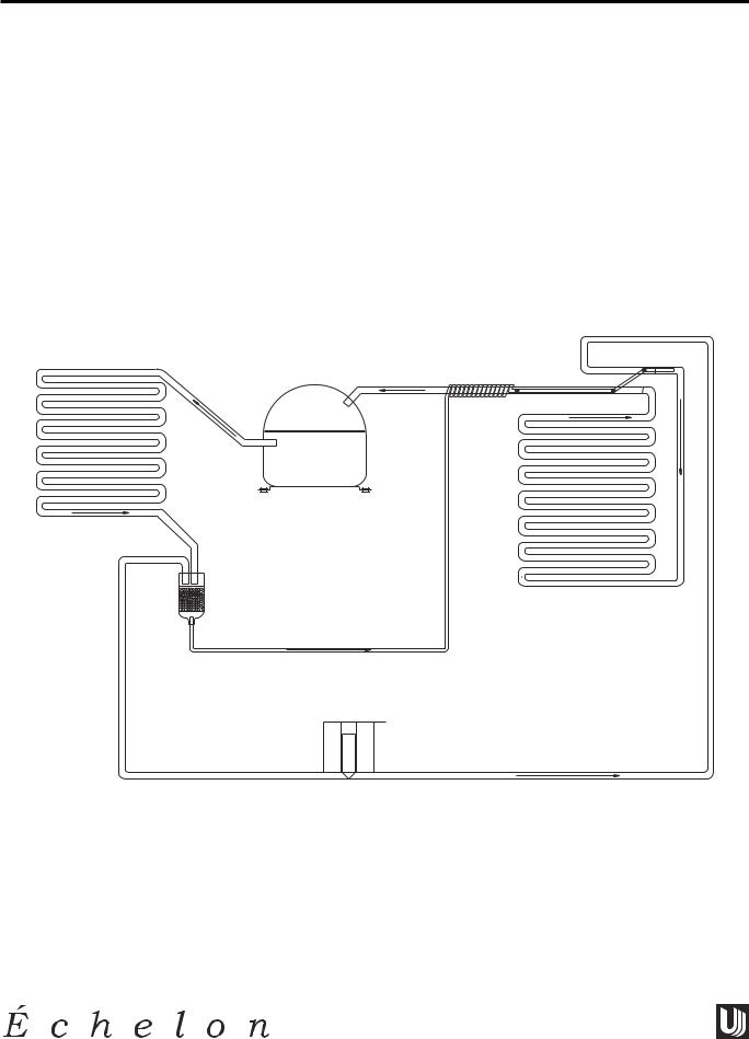
U-LINE FROST FREE REFRIGERATION SYSTEM
Cooling Mode:
•Bypass solenoid valve closed
•Evaporator fan operating
•Refrigerant flows through capillary tube
•Normal vapor/compression cycle refrigeration
•Drain heater off
Defrost Mode:
•Bypass solenoid valve open
•Refrigerant flows through bypass system
•Vapor flows from condenser to evaporator without a phase change
•Drain heater on
COMPRESSOR
CONDENSER
DRYER |
EVAPORATOR |
|
FLOW WHEN SOLENOID |
|
VALVE IS CLOSED |
|
CAPILLARY TUBE |
FLOW WHEN SOLENOID
VALVE IS OPEN
SOLENOID VALVE
UL183-2
18

Design ■ Features ■ Performance
CO2075FF/2075RF & U-CO29FF MODELS
TYPICAL FROST FREE AIRFLOW CONFIGURATION
Air flow in at evaporator blade

 Air passes though Air flow out at
  fin tube evaporator
evaporator outlet
Condensate drains down past the evaporator, into drain pan, and into condensate pan through drain hose. The drain trough is warmed during defrost by contact with evaporator fins and drain heater attached to the drain pan.
U-LINE1015
19
REFRIGERATION SYSTEM DIAGNOSIS GUIDE
|
|
System |
Suction |
Suction |
Compressor |
Condenser |
Capillary |
Evaporator |
Wattage |
|
|
Condition |
Pressure |
Line |
Discharge |
|
Tube |
|
|
|
|
|
|
|
|
|
|
|
|
|
|
Normal |
Normal |
Slightly below |
Very hot |
Very hot |
Warm |
Cold |
Normal |
|
|
|
|
room |
|
|
|
|
|
|
|
|
|
temperature |
|
|
|
|
|
|
|
|
|
|
|
|
|
|
|
|
|
Overcharge |
Higher than |
Very cold |
Slightly warm |
Hot to warm |
Cool |
Cold |
Higher than |
|
|
|
normal |
may frost |
to hot |
|
|
|
normal |
|
|
|
|
heavily |
|
|
|
|
|
|
|
|
|
|
|
|
|
|
|
|
|
Undercharge |
Lower than |
Warm - near |
Hot |
Warm |
Warm |
Extremely cold |
Lower than |
|
|
|
normal |
room |
|
|
|
near inlet - |
normal |
|
|
|
|
temperature |
|
|
|
outlet |
|
20 |
|
|
|
|
|
|
|
below room |
|
|
|
|
|
|
|
|
temperature |
|
|
|
|
|
|
|
|
|
|
|
|
|
|
|
|
|
|
|
|
|
|
|
|
Partial |
Somewhat |
Warm - near |
Very hot |
Top passes |
Room |
Extremely cold |
Lower than |
|
|
Restriction |
lower than |
room |
|
warm - |
temperature |
near inlet - |
normal |
|
|
|
normal-in |
temperature |
|
lower passes |
(cool) or |
outlet |
|
|
|
|
vacuum |
|
|
cool |
colder |
below room |
|
|
|
|
|
|
|
(near room |
|
temperature |
|
|
|
|
|
|
|
temperature) |
|
backing up |
|
|
|
|
|
|
|
due to liquid |
|
|
|
|
|
|
|
|
|
|
|
|
|
|
|
Complete |
In deep |
Room |
Room |
Room |
Room |
No |
Lower than |
|
|
Restriction |
vacuum |
temperature |
temperature |
temperature |
temperature |
refrigeration |
normal |
|
|
|
|
(cool) |
(cool) |
(cool) |
(cool) |
|
|
|
|
|
|
|
|
|
|
|
|
|
|
No |
0 PSIG |
Room |
Cool |
Room |
Room |
No |
Lower than |
|
|
Gas |
to |
temperature |
to |
temperature |
temperature |
refrigeration |
normal |
|
|
|
25" |
(cool) |
hot |
(cool) |
(cool) |
|
|
|
|
|
|
|
|
|
|
|
|
|
|
|
|
|
|
|
|
|
|
|
|
|
|
|
|
|
|
|
|
MODELS CO29FF-U & CO2075FF/2075RF
Performance ■ Features ■ Design

Design ■ Features ■ Performance
CO2075FF/2075RF & U-CO29FF MODELS
CO2075FF AND U-CO29FF ICE MAKER OPERATION
Note: The refrigeration system operates independently of the ice maker. This is a new design for U-Line. All other U-Line ice makers use a double throw control system where the unit is either in a freeze mode or harvest mode. In the CO2075FF and the U-CO29FF the refrigeration system will cycle on and off depending on the temperature of the freezer. In most cases this means the refrigeration system will be operating during the ice making and harvest modes. If the freezer control is set too warm the refrigeration system may cycle off during ice making mode, slowing the ice production rate. If this happens adjust the freezer control colder.
Ice Maker Operating Cycles
1.Freeze Cycle
A.Ice maker thermostat (located behind grille) open.
B.Freezer control closed and refrigeration system is operating.
2.Harvest Cycle-1
A.Ice maker thermostat closed.
B.Refrigeration system operating.
C.If bin arm is up the harvest will not initiate.
D.Power goes through the bin switch to the ice maker motor and mold heater.
3.Harvest Cycle-2
A.Ice maker ejector blades reach 2:00 position and cam depresses the hold switch.
B.Ejector blades stall on ice and ice maker motor pulsates until mold heater warms and ice releases.
C.Refrigeration system operating.
4.Water Fill Cycle
A.Ice maker blades reach approximately 10:00 position and cam depresses the water fill switch.
B.Power to the water valve. Ice maker mold fills.
C.Refrigeration system operating.
5.Eject Cycle
A.Ejector blades push ice into bucket and stop at 12:00 position.
B.Ice maker temperature control opens.
C.Refrigeration system still operating.
21

CO2075FF/2075RF & U-CO29FF MODELS
Design ■ Features ■ Performance
ICE MAKER DIAGNOSIS FLOW CHART
Sealed System Leak
Electrical Failure
Compressor Failure
Fan Motor Failure
Defrost System Failure
Freezer Control Open
DOES THE UNIT REFRIGERATE?
NO |
|
INTERMITTENT |
|
|
|
|
YES |
|
Low Voltage
Voltage Drop
Wiring
DOES THE UNIT HARVEST ICE
IF THE EJECTOR BLADES ARE
MOVED BY HAND OR WITH A
WRENCH ?
YES
Ice Maker Control Failure
Bin Switch Failure
NO
|
WHERE DO THE |
|
|
|
|
EJECTOR BLADES |
|
|
|
|
EVERYWHERE |
STOP? |
AT |
|
|
12:00AT |
3:00 |
||
|
|
|||
|
|
|
||
Ice Motor Failure |
|
|
|
|
Hold Switch Failure
Limit Switch Failure
Binding Cam/Ejector
IS THERE VOLTAGE AT THE
WATER SOLENOID VALVE
TERMINALS DURING HARVEST?
 Mold Heater Failure
NO
YES
Water Switch Failure |
Water Solenoid Valve Failure |
|
U-LINE1005 |
22
Design ■ Features ■ Performance
CO2075FF/2075RF & U-CO29FF MODELS
TROUBLESHOOTING |
! DANGER ! |
|
|
DO NOT service the unit until the main electrical power has |
|
1. Will not eject ice (water frozen) |
been disconnected. |
|
|
|
Cause
a.Icemaker control setting too cold.
b.Icemaker control defective (contacts open).
c.Bin switch defective.
d.Limit switch defective.
e.Ice maker assembly motor stalled.
f.Broken wire in ice maker circuit.
g.Dirty condenser.
h.Door gasket not sealing.
i.Refrigerant leak causing slight undercharge.
2. Will not fill with water
Cause
a.No water supply to unit.
b.Water switch defective.
c.Solenoid valve defective.
d.Fill tube frozen.
e.Broken wire in water fill circuit.
f.Fill tube kinked.
g.Inlet screen on water valve obstructed.
3. Will not stop making ice
Cause
a.Bin switch defective.
b.Bin arm not raising up completely.
4. Water will not stop filling
Cause
a.Water switch defective.
b.Solenoid valve defective.
c.Stalled ice maker motor.
d.Icemaker temperature control defective. Ice maker is in continuous harvest cycle (contacts closed).
5. Ejector blades will not stop turning
Cause
a.Water switch defective (closed).
b.Hold switch defective.
c.Defective wiring.
d.Short in mold heater.
6. Low ice production
Cause
a. Icemaker control set too cold.
Remedy
a.Adjust icemaker control warmer (counterclockwise).
b.Replace icemaker control.
c.Replace bin switch.
d.Replace limit switch.
e.Replace motor.
f.Replace defective wiring.
g.Clean condenser.
h.Replace gasket of fix obstruction.
i.Find and repair leak/replace refrigerant.
Remedy
a.Open water supply connection.
b.Replace switch.
c.Replace valve.
d.Replace solenoid valve and defrost the fill tube.
e.Replace defective wiring.
f.Straighten out tube.
g.Clean or replace valve.
Remedy
a.Replace bin switch.
b.Lubricate pivot point, loosen bin arm lever screw, or replace bent bin arm.
Remedy
a.Replace switch.
b.Replace solenoid valve.
c.Replace motor and solenoid valve.
d.Replace icemaker temperature control.
Remedy
a.Replace water switch
b.Replace hold switch.
c.Repair or replace wiring.
d.Replace heater.
Remedy
a.Adjust icemaker control warmer (counterclockwise).
23

CO2075FF/2075RF & U-CO29FF MODELS
Design ■ Features ■ Performance
b. |
Fan motor stalled. |
b. |
Replace fan motor. |
c. |
Ice cubes too large. |
c. |
Lower water fill adjustment. |
d. |
Dirty condenser. |
d. |
Clean condenser. |
e. |
Bypass valve stuck open. |
e. |
Replace bypass valve. |
7.Not freezing (compressor and fans are operating)
Cause |
|
Remedy |
a.Little or no frost pattern on evaporator.
b.Bypass valve stuck open.
8.Not freezing (compressor not operating - fans operating)
Cause
a.Relay defective.
b.Overload defective (open).
c.Compressor defective.
9.Not freezing (compressor and fans not operating)
Cause
a.On-off switch defective (open).
b.Hold switch defective (open).
c.Freezer control defective (open).
d.Broken wire in compressor circuit.
e.Power cord not plugged in.
f.On-off switch in off position (FF only).
g.Freezer control in off position.
h.Ejector blades not in the freeze position (12:00).
10. Compressor overheating
Cause
a.Condenser air flow restricted.
b.Condenser fan blade obstructed.
c.Condenser fan motor stalled.
d.Defective compressor.
11.Compressor will not stop operating
Cause
a.Freezer control set too cold.
b.Freezer control defective (contacts will not open).
c.Control sensing bulb not sensing freezer temperature.
d.Evaporator fan stalled.
12. Water leak (under unit)
Cause
a.Check for sealed system leak or restriction.
b.Replace bypass valve.
Remedy
a.Replace relay.
b.Replace overload.
c.Replace compressor.
Remedy
a.Replace on-off switch.
b.Replace hold switch.
c.Replace freezer control.
d.Repair or replace wiring.
e.Plug in power cord.
f.Put switch in on position.
g.Rotate freezer control knob clockwise.
h.Manually advance the ejector blades to the 12:00 position (test ice maker and limit switch).
Remedy
a.Remove restriction (clean condenser and grille).
b.Remove blade restriction.
c.Replace fan motor.
d.Replace compressor.
Remedy
a.Adjust freezer control warmer (counterclockwise).
b.Replace freezer control.
c.Fully insert bulb into well tube on side of freezer, routing bulb away from compressor discharge tube.
d.Remove obstruction or replace motor.
Remedy
a.Water supply line leaking at solenoid valve inlet.
b.Water line leaking at solenoid valve outlet.
c.Water line leaking at fill tube.
a.Tighten or replace fitting.
b.Replace water line and fitting.
c.Tighten clamp on fill tube or replace fill tube assembly.
24
Design ■ Features ■ Performance
CO2075FF/2075RF & U-CO29FF MODELS
d.Defrost drain line not in drain pan.
e.Crack in water line.
13. Water leak (inside unit)
Cause
a.Ice maker assembly fill cup obstructed.
b.Fill ice cup and fill tube out of alignment.
c.Water level too high.
d.Defrost drain plugged.
14. Excessive frost build-up
Cause
a.Door gasket not sealing properly.
b.Door out of alignment.
c.Water soaked cabinet insulation.
d.Light stays on when door is closed.
15. Noisy
Cause
a.Copper refrigeration tube touching cabinet.
b.Fan blade touching shroud.
c.Fan blade obstruction (wiring, foam insulation, packaging material).
16.Ice build-up in drain trough or drainage problem.
Cause
a.Obstructed drain cup or tube.
b.Evaporator not touching drain trough.
c.Kinked drain tube.
d.Drain trough spout and drain cup not aligned.
17. Unit will not defrost
Cause
a.Bypass valve not vertical (will not operate).
b.Bypass coil defective.
c.Defrost timer defective.
d.Bypass valve defective.
18. Fresh food temperature too cold
Cause
a.Ice bucket not fully inserted.
b.Freezer temperature control set too cold.
d.Position drain line in drain pan.
e.Replace water line.
Remedy
a.Remove obstruction.
b.Align fill tube and fill cup.
c.Adjust water level.
d.Ice in drain trough (refer to #16).
Remedy
a.Adjust door hinges or replace door gasket.
b.Align door hinges.
c.Replace foamed cabinet assembly (factory repair only).
d.Repair or adjust light bracket.
Remedy
a.Carefully adjust tubing.
b.Adjust fan mounting or shroud.
c.Remove obstruction.
Remedy
a.Clear obstruction.
b.Reposition evaporator to contact drain trough along entire length.
c.Reposition drain tube.
d.Align drain trough and drain cup.
Remedy
a.Align bypass valve and coil assembly.
b.Replace bypass valve.
c.Replace defrost timer.
d.Replace bypass valve.
Remedy
a.Push ice bucket in place.
b.Adjust freezer control to warmer setting (counterclockwise).
25
CO2075FF/2075RF & U-CO29FF MODELS
Design ■ Features ■ Performance
2
3
4
2
1
4 |
U-LINE1004 |
|
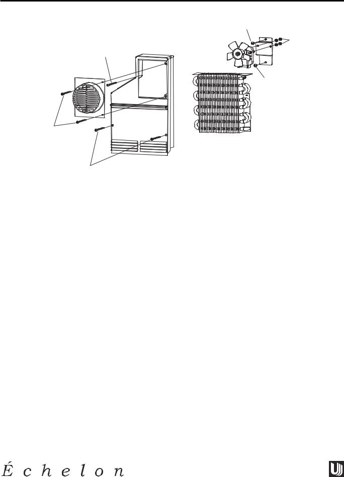
DISASSEMBLY PROCEDURES
Note: Échelon models do not require removal of the ice maker or freezer housing to access the fan motor, drain or evaporator.
To replace evaporator fan motor:
1.Disconnect unit from power source.
2.Remove 2 screws (1) from fan cover.
3.Remove 2 screws (2) holding fan bracket to liner.
4.Unplug fan connection.
5.Remove 2 nuts (3) holding the fan to the fan bracket.
6.Replace with new fan.
7.Plug in the fan connection.
8.Re-install fan bracket to liner making sure the fan wires are tucked behind the fan bracket.
9.Re-install unit and test.
To access evaporator or drain:
1.Disconnect unit from power source.
2.Remove 2 screws (1) from fan cover.
3.Remove 3 screws (4) from evaporator cover.
4.To remove, pull evaporator cover forward and turn.
26
Design ■ Features ■ Performance
CO2075FF/2075RF & U-CO29FF MODELS
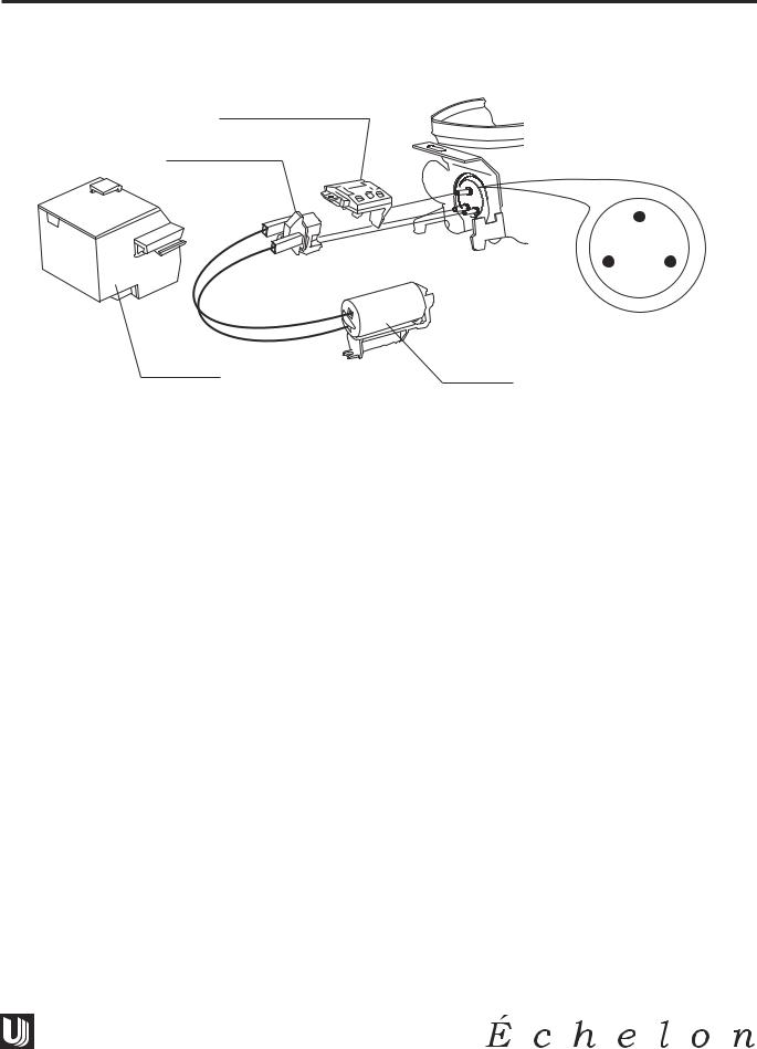
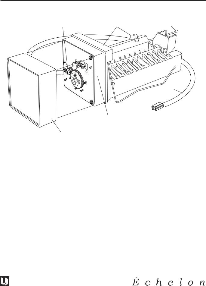
REPLACING ICE MAKER ASSEMBLY
4 |
5 |
2 |
1
5 |
U-LINE1001 |
3
1.Unplug unit.
2.Disconnect ice maker wire harness at plug (1).
3.Remove control capillary tube from sensing tube on ice maker assembly (2).
4.Remove water inlet tube.
5.Remove front cover (3).
6.Advance ejector blade to the 3 o’clock position by turning the 5/16" hex head on the small brass gear counterclockwise (4).
7.Remove three screws from wall of freezer housing (5).
8.Remove ice maker assembly.
9.Install new ice maker assembly.
10.Reconnect plug.
11.Insert control capillary tube into ice maker sensing tube.
12.Insert water inlet tube.
13.Apply Permagum® to all exit holes.
14.Install back panel.
15.Plug in unit and test.
27
CO2075FF/2075RF & U-CO29FF MODELS
Design ■ Features ■ Performance
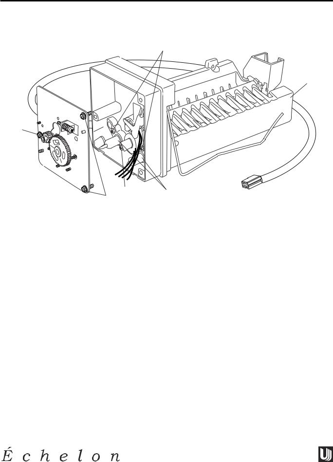
REPLACING MOLD AND HEATER
5
1
2
3 4
2
U-LINE1002
1.Remove ice maker assembly. Refer to REPLACING ICE MAKER ASSEMBLY.
2.Remove one stripper screw (1) and stripper.
3.Remove three face plate screws (2) and face plate.
4.Remove one screw (3) and detach limit switch from mold.
5.Detach heater leads (4).
6.Remove two screws (5) and mold from support housing.
7.To assemble, replace parts in reverse order.
8.Install the ice maker assembly.
28

Design ■ Features ■ Performance
CO2075FF/2075RF & U-CO29FF MODELS
COMBO 2075FF WIRING DIAGRAM
POWER CORD ASSEMBLY
|
BLACK-HOT |
|
|
ROCKER |
|
|
|
|
|
|
|
|
SWITCH |
|
|
|
|
||
|
(SMOOTH) |
|
|
|
ICEMAKER |
|
|
||
|
|
|
|
|
|
|
|
|
|
|
|
|
|
|
|
|
CONTROL |
|
|
|
BLACK-NEUTRAL |
GREEN |
|
|
|
|
|
||
|
GROUND |
BLACK |
|
|
|
|
|||
|
(RIBBED) |
|
|
|
|
|
|||
|
|
|
|
|
|
|
|||
|
|
|
|
|
|
|
|
||
FREEZER |
|
|
|
|
YELLOW |
YELLOW |
|
|
|
|
|
|
|
RED |
RED |
|
|
||
CONTROL |
|
|
|
|
|
|
|||
|
|
|
|
|
|
WHITE |
WHITE |
|
|
BLUE |
|
|
WHITE |
WATER |
BROWN |
BROWN |
|
|
|
|
|
|
|
|
|
||||
|
WHITE |
|
|
|
BLACK |
BLACK |
|
|
|
|
|
|
|
VALVE |
|
|
|||
|
|
|
|
|
|
|
|
||
|
WHITE |
|
|
BROWN |
|
5 PIN CONNECTOR |
|
|
|
|
|
|
|
|
|
|
|||
|
|
|
|
|
|
|
OVERLOAD |
||
|
|
|
|
BLACK |
BLACK |
BLACK |
|
|
|
|
|
|
|
|
|
|
|
|
|
|
|
|
|
BLACK |
|
|
|
|
|
|
|
|
|
|
|
|
WHITE |
|
|
WHITE |
BLACK |
|
|
DOOR |
|
|
|
|
|
|
|
L |
LAMP |
|
|
|
|
|
|
|
|
|
|
|
|
|
|
||
|
|
|
A |
SWITCH |
|
RELAY |
BLACK |
|
|
|
|
|
M |
|
|
EMBRACO |
|
|
|
|
|
|
P |
|
|
|
CAPACITOR |
|
|
BYPASS |
|
BLACK |
|
|
COMPRESSOR |
|
|||
|
|
|
|
|
|
||||
VALVE |
|
|
|
|
|
|
|
|
|
WHITE |
BLACK |
|
|
|
|
|
|
|
|
|
|
|
PURPLE |
|
|
|
|
|
|
DEFROST |
|
|
WHITE |
|
EVAP |
COND |
|
||
HEATER |
|
|
|
FAN |
FAN |
|
|
||
|
|
|
|
|
|
||||
|
2 |
1 |
4 |
3 |
PURPLE |
BLACK |
|
WHITE |
|
|
|
TIMER |
|
||||||
|
|
|
PURPLE |
|
|
||||
|
|
|
|
|
|
|
|
||
BLUE |
|
|
|
|
|
|
BLUE |
|
|
U-CO29FF WIRING DIAGRAM
POWER CORD ASSEMBLY
|
BLACK-HOT |
|
|
ROCKER |
|
|
|
|
|
|
|
|
SWITCH |
|
|
|
|
||
|
(SMOOTH) |
|
|
|
ICEMAKER |
|
|
||
|
|
|
|
|
|
|
|
|
|
|
|
|
|
|
|
|
CONTROL |
|
|
|
BLACK-NEUTRAL |
GREEN |
|
|
|
|
|
||
|
GROUND |
BLACK |
|
|
|
|
|||
|
(RIBBED) |
|
|
|
|
|
|||
|
|
|
|
|
|
|
|||
FREEZER |
|
|
|
|
YELLOW |
YELLOW |
|
|
|
|
|
|
|
|
|
|
|
||
CONTROL |
|
|
|
|
RED |
RED |
|
|
|
|
|
|
|
|
|
WHITE |
WHITE |
|
|
BLUE |
WHITE |
|
|
WHITE |
WATER |
BROWN |
BROWN |
|
|
|
|
|
|
|
|
||||
|
|
|
|
|
BLACK |
BLACK |
|
|
|
|
|
|
|
|
VALVE |
|
|
||
|
|
|
|
|
|
|
|
|
|
|
|
|
|
BROWN |
|
5 PIN CONNECTOR |
|
|
|
|
|
|
|
|
|
|
OVERLOAD |
||
|
|
|
|
|
BLACK |
BLACK |
|
|
|
|
|
|
|
|
|
|
WHITE |
|
|
WHITE |
BLACK |
|
|
|
|
|
|
|
|
|
|
|
|
|
|
|
|
|
|
|
|
|
|
|
|
|
BLACK |
|
|
|
|
|
|
|
|
RELAY |
EMBRACO |
|
|
|
|
|
|
|
|
|
CAPACITOR |
|
|
BYPASS |
|
BLACK |
|
COMPRESSOR |
|
||||
|
|
|
|
|
|
||||
VALVE |
|
|
|
|
|
|
|
|
|
WHITE |
BLACK |
|
|
|
|
|
|
|
|
|
|
|
PURPLE |
|
|
|
|
|
|
DEFROST |
|
|
WHITE |
|
EVAP |
COND |
|
|
|
HEATER |
|
|
|
FAN |
FAN |
|
|
||
|
|
|
|
|
|
||||
|
2 |
1 |
4 |
3 |
PURPLE |
|
BLACK |
|
WHITE |
|
|
TIMER |
|
|
|||||
|
|
|
|
|
|||||
|
|
|
PURPLE |
|
|
||||
|
|
|
|
|
|
|
|
||
BLUE |
|
|
|
|
|
|
BLUE |
|
|
ICEMAKER ASSEMBLY
RED
|
|
NO NC |
|
|
|
BIN |
|
|
|
SW |
|
|
ORANGE C |
BROWN |
|
|
WHITE |
|
|
|
|
|
|
|
C |
|
NC NO |
|
|
|
|
|
HOLD |
|
WATER |
NO |
SW |
CAM |
SW |
NC |
|
C |
|
|
|
|
|
|
|
|
BLACK |
YELLOW |
|
|
|
|
ORANGE |
3 RPM ORANGE |
|
|
|
MOTOR |
|
|
BLACK |
|
BLACK |
|
MOLD HEATER |
|
|
|
BLACK |
LIMIT |
BLACK |
|
|
|
|
SW
BROWN
U-LINE42130
ICEMAKER ASSEMBLY
RED
NO NC
BIN
SW
|
ORANGE |
C |
BROWN |
|
|
WHITE |
|
|
|
|
|
|
|
|
|
C |
|
|
NC NO |
|
|
|
|
|
|
HOLD |
|
|
WATER |
NO |
SW |
|
CAM |
SW |
|
|
|
||
NC |
|
|
C |
|
|
|
|
|
|
|
|
|
|
BLACK |
YELLOW |
|
|
|
|
|
ORANGE |
|
3 RPM ORANGE |
|
|
|
MOTOR |
|
|
|
BLACK |
|
|
BLACK |
|
MOLD HEATER |
|
||
|
BLACK |
LIMIT |
BLACK |
|
|
|
|
||
SW
BROWN
U-LINE42180
29
Loading...