


 Loading...
Service and Parts Manual

U-LINE CORPORATION LIMITED WARRANTY FOR MODULAR 3000 SERIES PRODUCTS
1.U-Line Corporation ("U-Line") warrants each U-Line Modular 3000 Series product to be free from defects in materials and workmanship for a period of two years from the date of purchase. U-Line further warrants the sealed system (consisting of the compressor, the condenser, the evaporator, the hot gas bypass valve, the dryer and the connecting tube) in each U-Line product to be free from defects in materials and workmanship for a period of five years from the date of purchase.
2.During the initial two year warranty period for all U-Line Modular 3000 Series products U-Line shall: (1) repair any product or replace any part of a product; and (2) for all Domestic U-Line Modular 3000 Series products sold and serviced in the United States (including Alaska and Hawaii) and Canada, U-Line shall be responsible for the labor costs performed by a U-Line authorized service company, incurred in connection with the replacement of any defective part. During years two through five of the warranty period for the sealed system, U-Line shall: (1) at U-Line's option repair or replace any part of the sealed system; and (2) for all Domestic U-Line Modular 3000 Series products sold and serviced in the United States (including Alaska and Hawaii) and Canada, U-Line shall be responsible for the labor costs incurred in connection with the replacement of any defective part of the sealed system. All other charges, including transportation charges for replacements under this warranty and labor costs not specifically covered by this warranty, shall be the responsibility of the purchaser. This warranty extends only to the original purchaser of the U-Line product. The registration Card included with the product should be promptly completed by you and mailed back to U-Line or you can register on-line at www.u-lineservice.com.
3.The following conditions are excluded from this limited warranty: damage caused by outdoor use; use of cleaners other than the recommended stainless steel cleaners and U-Line Clear Ice Maker cleaner; installation charges; damages caused by disasters or acts of God, such as fire, floods, wind and lightning; damages incurred or resulting from shipping, improper installation, unauthorized modification, or misuse/abuse of the product; customer education calls; food loss and spoilage; door and water level adjustments (except during the first 30 days from the date of installation); defrosting the product; adjusting the controls; door reversal; and cleaning the condenser.
4.U-Lines' Outdoor Limited Warranty, set forth in this Paragraph 4, shall apply to U-Line models deemed suitable for outdoor use by Underwriters Laboratory ("UL") as noted in the U-Line Product Catalog, U-Line's website and/or on the serial tag located inside the product. Exposure to temperatures below freezing may cause damage to the product. Damage resulting to the product (and/or the surroundings) caused by this exposure is not covered under this warranty. Such models shall continue to be covered by the warranty terms set forth in Paragraphs 1 and 2 above, to the extent such models:
A.Are subjected to temperatures between 50 and 100 degrees Fahrenheit. Although these products will function in ambient temperatures below 50 degrees and above 100 degrees Fahrenheit, performance may decline. Performance degradation due to operating above or below the designated ambient temperature range is not a manufacturing defect and any issues resulting from exposure to higher temperatures, such as spoiled food or low ice production, are not covered under this warranty policy; and/or
B.Come into contact with rain by virtue of outdoor use. Exposure to other sources of water shall also cause this warranty to be void, including flooding of the area in proximity of the unit greater than 1/8" deep in water, hurricanes, splashing of pool water, or directing a spray from a hose or similar device into and around the unit.
5.If a product defect is discovered during the applicable warranty period, you must promptly notify either U-Line at P.O. Box 245040, Milwaukee, Wisconsin 53224 or at 800-779-2547 or the dealer from whom you purchased the product. In no event shall such notification be received later than 30 days after the expiration of the applicable warranty period. U-Line may require that defective parts be returned, at your expense, to U-Line's factory in Milwaukee, Wisconsin, for inspection. Any action by you for breach of warranty must be commenced within two years after the applicable warranty period.
6.THIS LIMITED WARRANTY IS IN LIEU OF ANY AND ALL OTHER WARRANTIES, EXPRESS OR IMPLIED, INCLUDING ANY IMPLIED WARRANTY OF MERCHANTABILITY OR IMPLIED WARRANTY OF FITNESS FOR A PARTICULAR PURPOSE, ALL OF WHICH ARE DISCLAIMED. U-Line's sole liability and your exclusive remedy under this warranty is set forth in the paragraphs above. U- Line shall have no liability whatsoever for any incidental, consequential or special damages arising from the sale, use or installation of the product or from any other cause whatsoever, whether based on warranty (express or implied) or otherwise based on contract, tort or any other theory of liability.
7.Some states do not allow limitations on how long an implied warranty lasts or the exclusion or limitation of incidental or consequential damages, so the above limitations may not apply to you. This warranty gives you specific legal rights, and you may also have other rights which vary from state to state.
U-Line Warranty
PRODUCT LIABILITY POLICY
Field service technicians are authorized to make an initial assessment. If in the servicer’s judgment the damage is the result of a product defect, the product would be removed and returned to U-Line in an unaltered condition. The dealer would then be authorized to permanently replace the end-user’s product at no cost to the end-user. Please call U-Line immediately at 800-779-2547 to initiate the RA and product exchange process.
If in the servicer’s judgment the damage is the result of installation issues (water connection/drain, etc.), the consumer would be so notified and the correction would be made by the servicer or installer without requiring removal of the product. Any claim for damages should be directed to the original installer.
Any U-Line unit involved in an alleged property damage claim must remain unaltered and unrepaired, for evaluation. No service or repairs should be performed on any unit suspected to be involved in a property damage situation. If a unit has been altered or repaired in the field prior to U-Line’s evaluation, any claim for damage may be declined.
If the unit in question is a U-Line CLR or CLRCO with a drain pump, both the unit and the drain pump (regardless of the manufacturer) must be returned to U-Line Corporation.
To complete the damage claim process for the customer, please obtain the following and forward to U-Line at onlineservice@U-Line.com, fax to 414-354-5696 or mail to the address below.
Pictures of the unit, installation and any alleged property damage.
Inquire when the problem first appeared, any prior problems with the product and provide a brief description of the alleged damages.
To expedite the claim process, U-Line will need two damage repair estimates. Reference the RA number and customer name when providing this information.
If a unit is returned to U-Line, this evaluation will take approximately ten business days. No field service company is authorized to perform this evaluation. When a Return Authorization Number is issued, and the unit has been boxed in a U-Line carton, U-Line should be contacted and then will make arrangements for shipping, or designate a truck line to have the unit shipped freight collect.
If U-Line’s evaluation finds the unit, (or U-Line P60 pump) to be defective, causing the property damage, the damage claim will be reviewed by the U-Line Customer Assurance Department.
If U-Line’s evaluation finds the unit not to be defective, does not repeat a failure or does not leak any water from the U-Line unit or U-Line P60 pump, all claims for damage will be declined.
When a product evaluation is needed, it is the customer’s responsibility to assure that the unit is returned for evaluation. If the customer fails to do so, or has the unit repaired in the field prior to U-Line’s evaluation, any claim for damage will be declined.
8900 N. 55th St. • P.O. Box 245040
Milwaukee, WI 53224-9540
414/354-0300 • Fax: 414/354-7905
Website: www.u-line.com
Leaders In Quality Undercounter Refrigeration
U-Line Service
THIS PAGE INTENTIONALLY LEFT BLANK
U-Line Service

Table Of Contents |
|
General Information |
|
Safety Alert Definitions......................................................................................................................................... |
1 |
General Precautions ............................................................................................................................................. |
1 |
Models Covered..................................................................................................................................................... |
2 |
Warranty Claims Procedure ............................................................................................................................... |
3 |
Proof of Purchase................................................................................................................................................... |
3 |
Serial Number ........................................................................................................................................................ |
4 |
Model Number Format ....................................................................................................................................... |
4 |
Replacement Parts ................................................................................................................................................ |
5 |
Thermistor Info ...................................................................................................................................................... |
6 |
Thermistor Calibration......................................................................................................................................... |
6 |
Viewing Temperature............................................................................................................................................ |
6 |
Air Flow.................................................................................................................................................................... |
7 |
Initial Startup ........................................................................................................................................................... |
7 |
OLED Electronic Control Display ..................................................................................................................... |
7 |
Adjusting Temperature Settings ........................................................................................................................ |
7 |
Interior Lighting ..................................................................................................................................................... |
8 |
Customer Menu ..................................................................................................................................................... |
8 |
Service Menu......................................................................................................................................................... |
10 |
Electronic Control Quick Guide .............................................................................................. |
17 |
USB Communication........................................................................................................................................... |
18 |
Convection Cooling ............................................................................................................................................ |
22 |
Door Alignment and Adjustment..................................................................................................................... |
23 |
Troubleshooting |
|
Customer Call Guide .......................................................................................................................................... |
24 |
Compressor Information ................................................................................................................................... |
26 |
Thermistors .......................................................................................................................................................... |
26 |
Thermistor Failure .............................................................................................................................................. |
27 |
Reed Switch........................................................................................................................................................... |
27 |
Compressors....................................................................................................................................................... |
27 |
Refrigeration System Diagnosis Guide............................................................................................................ |
28 |
Fault System Diagnosis Guide .......................................................................................................................... |
29 |
Parts View & Listing |
|
3036BVWC .......................................................................................................................................................... |
30 |
3036RRGL ............................................................................................................................................................ |
32 |
3036RR .................................................................................................................................................................. |
34 |
3036WCWC ....................................................................................................................................................... |
36 |
Wiring Diagrams |
|
All Models ............................................................................................................................................................. |
38 |
General Information
General Information
IMPORTANT
•PLEASE READ all instructions before installing, operating, or servicing the appliance.
•Proper installation procedures must be followed when completing an installation or relocation of a unit. An INSTALLATION GUIDE for the unit, providing complete installation information is available from U-Line Corporation direct. Consult the installation guide before any installation begins. U-Line contact information appears on the rear cover of this guide.
•This unit requires connection to a dedicated 15 Amp grounded (three-prong), polarized receptacle, installed by a qualified electrician, compliant with applicable electrical codes.
Safety Alert Definitions
Throughout this guide are safety items labeled with a Danger, Warning or Caution based on the risk type:
 DANGER
Danger means that failure to follow this safety statement will result in severe personal injury or death.
 WARNING
Warning means that failure to follow this safety statement could result in serious personal injury, property or equipment damage. or death.
 CAUTION
Caution means that failure to follow this safety statement may result in minor or moderate personal injury, property or equipment damage.
General Precautions
Use this appliance for its intended purpose only and follow these general precautions with those listed throughout this guide:
 DANGER
RISK OF CHILD ENTRAPMENT. Before you throw away your old refrigerator or freezer, take off the doors and leave shelves in place so children may not easily climb inside.
 WARNING
•SHOCK HAZARD - Electrical Grounding Required.
•Never attempt to repair or perform maintenance on the unit until the electricity has been disconnected.
•Never remove the round grounding prong from the plug and never use a two-prong grounding adaptor.
•Altering, cutting of power cord, removal of power cord, removal of power plug, or direct wiring can cause serious injury, fire and or loss of property and or life, and will void the warranty.
•Never use an extension cord to connect power to the unit.
•Always keep your working area dry.
 WARNING
Install provided Anti-Tip kit. Serious personal injury could occur.
 CAUTION
•Use care when moving and handling the unit. Use gloves to prevent personal injury from sharp edges.
•If your model requires defrosting, DO NOT use an ice pick or other sharp instrument to help speed up defrosting. These instruments can puncture the inner lining or damage the cooling unit. DO NOT use any type of heater to defrost. Using a heater to speed up defrosting can cause personal injury and damage to the inner lining.
IMPORTANT
•Do not lift unit by door handle.
•Never install or operate the unit behind closed doors. Be sure front grille is free of obstruction. Obstructing free airflow can cause the unit to malfunction and will void the warranty.
•Failure to clean the condenser every six months can cause the unit to malfunction. This could void the warranty.
•Allow unit temperature to stabilize for 24 hours before use.
•Do not Block any internal Fans
Use only genuine U-Line replacement parts. Imitation parts can damage the unit, affect its operation or performance and may void the warranty.
1 |
U-Line Service |

General Information
Models Covered
This guide covers the following models:
U-3036BVWCOL-00 U-3090BVWCOL-00 U-3036BVWCS-00 U-3090BVWCS-00 U-3036RRGLOL-00 U-3090RRGLOL-00 U-3036RRGLS-00 U-3090RRGLS-00 U-3036RROL-00 U-3090RROL-00 U-3036RRS-00 U-3090RRS-00 U-3036WCWCOL-00 U-3090WCWCOL-00 U-3036WCWCS-00 U-3090WCWCS-00
U-3036BVWCOL-00
U-3036BVWCS-00
U-3036RRS-00
U-3036RROL-00
U-Line Service |
2 |

General Information
Warranty Claims Procedure
IMPORTANT
Warranty claims must be filed within 60 days after the completion of the service call
When submitting claims for warranty payment, please follow these guidelines.
You can use any form you would normally use to bill your customer (your own computer generated form, Narda, USA, etc.). Claims can also be filed on-line at www.u-lineservice.com.
The model and serial number MUST be on the claims. Claims will not be paid without a model and serial number.
If you used a part in your repair, you MUST put the part number, the invoice number and where the part came from. Claims will be returned without this information.
If you work on more than one unit per service call please submit a separate claim for each unit.
We track all defects through warranty claims, so please be specific on what the repair was. If it is a system leak, please specify where the leak was.
Please be sure the claim is legible. If the claim form cannot be read, it will be returned, unpaid.
Remember: Door and water level adjustments are 30 day warranties only.
If you are changing out a unit please supply the model and serial number of both units (the unit being replaced and the new unit) and the R.A. number.
Occasionally the customer does not return their warranty cards. In this case we use the date the unit was shipped to our distributor for a beginning warranty date. This may cause the claim to be rejected for a proof of purchase. If you want to check on a purchase date, you may contact the U-Line Corporation Customer Assurance Department at 1-800-779-2547. This will allow you to get a proof of purchase, if needed, before you submit the claim.
At U-Line, parts and labor claims are paid separately. Included in labor are freon and recovery charges, all other parts are handled by the parts department. We require that some parts be returned to us, so we may return them to our vendor. It will be noted on your packing list if we require you to return the part. If a part is to be returned please include a copy of the packing list and a copy of your claim. If the part was purchased at one of our part distributors, you must handle the part warranty with that company. For labor payment please send a readable copy of your claim to U-Line Corporation, P.O. Box 245040, Milwaukee WI, 53224-9540, or fax it to 414-354- 5696. Claims can also be filed on-line at www.u-lineservice.com.
Proof of Purchase
Proof of Purchase and/or Proof of Install is an important part of the warranty claim process. Sometimes it is difficult to obtain a proper Proof of Purchase/Proof of Install for a number of different reasons:
•The customer does not have a copy (only the original).
•The customer has only their copy of the final Walk Through or sign-off of new construction.
•Other valid reasons that prevent your technician from leaving the job site with a suitable Proof of Purchase/ Proof of Install.
We understand the problem and have modified our Proof of Purchase policy to help you in these situations.
Effective immediately, if a copy of the Proof of Purchase/Proof of Install is not available at the site, the technician should record the following information on the Labor Invoice:
•The name of the selling Dealer
•The date of purchase/installation
•The Order or Invoice number (if available)
•The type of document they saw, i.e. Store Receipt, Closing Papers, Sign-Off of Building Permit, Final Walk Through, etc.
If we have this information on the Labor Invoice, and we have the other information that is needed (correct Serial Number, type of repair, time spent on repairs, parts used in the repair, invoice number for the part, etc.), we will be able to process the invoice for you in a timely manner.
3 |
U-Line Service |
General Information
Serial Number
IMPORTANT
Starting October 2009, U-Line Corporation went to a 13 digit serial number. Anything before that date will have 12 digits.
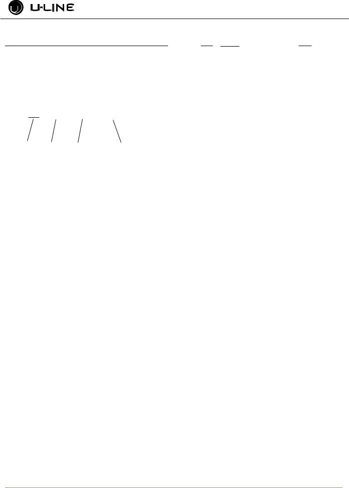
The serial number is divided into four segments. A typical serial number is 0914997-11-0005. (Figure 1)
Model Number Format
U - 2275 DWRW OL - 00
U-LINE |
PRODUCT |
FAMILY |
COLOR SPECIAL |
|
SERIES |
|
ORDER |
U - CO |
1175 |
|
S - |
01 |
|
||||
|
|
|
|
|
|
|
|
|
|
U-LINE FAMILY |
PRODUCT |
|
COLOR |
SPECIAL |
|||||
|
|
|
|
SERIES |
|
|
|
ORDER |
|
0914997-11-XXXX
Year Shop Month |
Factory Internal |
Order |
Control Number |
Number |
|
The first two digits of the first segment, 09, represents the year the unit was made.
The next four/five digits of the first segment, 14997, represent the shop order number. Order number 14997 is assigned for the Model CLRCO2175B-40 units.
The next two digit segment, 11, represents the month the unit was made.
The last four digit segment, XXXX, is a factory internal control number used at U-Line Corporation.
Serial Number (Electronic)
The 3000 series contains an electronic serial number assigned to the main control board. The electronic control serial number and the unit serial number are tied together at the factory. To obtain the electronic serial number access “Help” in the customer service menu. See “Help” on page 10.
|
ULN |
- BI |
2115 |
|
|
S - |
00 |
|
|||||||||||
|
|
|
|
|
|
|
|
|
|
|
|
|
|
|
|||||
U-LINE |
|
FAMILY |
|
PRODUCT COLOR |
SPECIAL |
||||||||||||||
|
|
|
|
|
|
SERIES |
|
|
|
|
ORDER |
||||||||
|
U - 2175 |
RC |
GOL - 00 |
||||||||||||||||
|
|
|
|
|
|
|
|
|
|
|
|
|
|||||||
U-LINE |
PRODUCT |
FAMILY |
|
COLOR |
|
SPECIAL |
|||||||||||||
|
|
|
SERIES |
|
|
|
|
|
|
|
|
ORDER |
|||||||
|
U - CLRCO |
2175 |
|
|
S - 41 |
||||||||||||||
|
|
|
|
|
|
|
|
|
|
|
|
|
|
|
|
|
|
|
|
U-LINE |
FAMILY |
|
|
|
PRODUCT |
COLOR |
SPECIAL |
||||||||||||
|
|
|
|
|
|
|
|
SERIES |
|
|
|
|
ORDER |
||||||
A typical model number would be, U-2175RCGOL-00. The model number is broken into 5 segments. (Figure 2)
•U- or ULNThis signifies a U-Line Product.
•Family The family is the type of unit. Currently there are nine families. Refrigerators, Wine Captains, Beverage Centers, Combo Ice Makers, Clear Ice Makers, Manual Defrost Ice Makers, ADA Units, Outdoor Units and Freezers.
•Product Series: U-Lines current product series includes 95, 98, SP18, 1095, 29, 10xx, 11xx, 21xx , 22xx, and 30xx.
•Color The color segment includes color along with information that is important to the unit and the way it is used. As an example, the model U-2175RCGOL- 00, is part of the family of refrigerators, product series 2175. The “C” following the “R” tells us this is a convection cool unit with an evaporator fan motor. The “GOL” tells us the unit is black with a glass door requiring an overlay panel. (all glass door overlay units are black)
•Special Order These numbers tells us if the unit is a SS door with a left hand hinge, (01) a CLR with a pump, (40) or a marine or RV product. (03)
U-Line Service |
4 |
General Information
Replacement Parts
How to Order Replacement Parts
1.Refer to Service Parts and locate the illustration(s) for the model you are servicing.
2.Locate the desired part to be serviced and note the item number assigned to it.
3.Locate the item number within the parts list. Note the full description and the corresponding part number. If this is for a warranty unit, indicate and record the model and serial numbers.
4.When ordering parts, it will be necessary to supply Model Number, Serial Number, Part Number, Part Description and in some cases Color or Voltage.
All warranty parts will be shipped at no charge as long as warranty status has been confirmed. If we require that a part be returned to U- line, you will be informed at the time the order is placed. It will be noted on your packing list if we require you to return a part or if you may field scrap it. If U-Line requires a defective part to be returned, a prepaid shipping label will be included with your new replacement part. When returning parts enclose a copy of your packing list and a copy of your labor claim, showing the model and serial number, and tag or label the part with the nature of the defect.
Our warranty records may not match the customer's information. In this case, a proof of purchase will be required. If you do not have the proof of purchase at the time the order is placed, the part will be sent net 15 days, charged to a Visa or Master Card if you don't have an open account with U-Line Corporation. When the proof of purchase is provided, we will credit your account.
5. Parts may be ordered on-line, by FAX or phone: www.U-LineService.com
onlineparts@u-line.com FAX Number (414) 354-7905
Phone Number (414) 354-0300 or (800) 779-2547;
REPLACEMENT PARTS: Use only genuine U-Line replacement parts. The use of non-U-Line parts can reduce ice rate, cause water to overflow from ice maker mold, damage the unit, and can void the warranty.
5 |
U-Line Service |
General Information
IMPORTANT
All relay and thermistor information can be found on the Electronic Control Quick Guide.
Thermistor Info
There are 5 thermistors used with the 3036 models.
•Left Zone Thermistor - Located on the right hand wall in the left zone and is used to maintain temperature.
•Right Zone Thermistor - Located on the right hand wall in the right zone and is used to maintain temperature
•Left Evap Thermistor - Located on the back of the evaporator plate in the left zone and is used during defrost. Normal defrosting is based on a time and temperature scale. Defrost ends if the evaporator thermistor reaches stop set point or maximum time.
•Right Evap Thermistor - Located on the back of the evaporator plate in the right zone and is used during defrost. Normal defrosting is based on a time and temperature scale. Defrost ends if the evaporator thermistor reaches stop set point or maximum time.
•Ambient Thermistor - Located in the base of the unit on the condenser and is used to monitor ambient air temperatures.
Thermistor Calibration
While thermistors generally do not require calibration, over time contact corrosion and or element wear may make calibration necessary.
IMPORTANT
If a thermistor reports a temperature difference in excess of 4°F, the thermistor should be replaced.
Calibration
To calibrate a thermistor one must first prepare an ice-bath of crushed ice and water in a suitable container. Allow the ice bath temperature to stabilize for at least 5 minutes before beginning.
1.Make certain the offset for the thermistor to be tested is set to 0. See “Offsets” on page 12
2.Fully submerge the thermistor to be calibrated in the prepared ice bath. It is important the thermistor is surrounded only by the ice bath and is not touching any walls of the container.
3.View temperature through the customer menu, see “Customer Menu” under “Viewing Temperature” on page 6.
4.The thermistor should read 32°F. If different, record difference. If difference is greater then 4°, replace thermistor.
5.Use recorded difference to adjust thermistor offset, see “Offsets” on page 12.
6.Repeat step 3 and confirm the new reading is 32°F.
Viewing Temperature
Note: The display shows set point NOT the actual temperature.
The 3000 series is equipped with an advanced electronic display and control. Thermistor readings can be obtained through both the customer and service menu. The customer menu will display readings with offset adjustments taken into consideration. It is important to note that the system will use adjusted readings when determining cooling and defrost cycles. The service menu will display the actual thermistor reading while disregarding offsets.
Customer Menu:
To view the adjusted temperature of each available thermistor, follow the steps below.
1.Initiate the customer menu by holding both up  and zone toggle
2.Use Up  or Down
  to scroll to “Actual Temperatures”.
3.Press select  .
.
4.Use Up  or Down
  to scroll through available information
Service Menu
To view the actual temperature without having the offsets taken into consideration, follow the steps below.
1.Initiate the service menu by holding both up  and select
2.Use Up  or Down
  to scroll to “Actual Temperatures”.
3.Press select  .
.
Use Up  or Down
  to scroll through available information
U-Line Service |
6 |
General Information
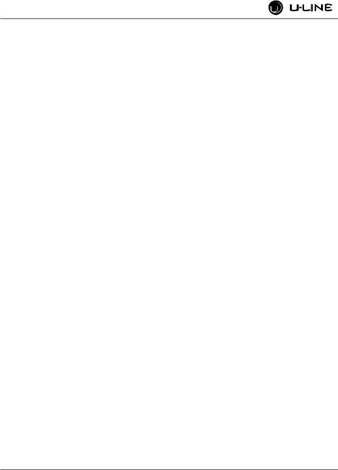
Air Flow
IMPORTANT
The unit requires proper air flow to perform at its highest efficiency. Do not block the front grille, internal fans or vents at any time, or the unit will not perform as expected. Do not install the unit behind a door.
Door Removed For Illustration Purposes
Internal Air Flow And Unit Ventilation Diagram
Initial Startup
All U-Line controls are preset at the factory. Initial startup requires no adjustments.
IMPORTANT
U-Line recommends allowing the unit to run overnight before loading refrigerator with product.
To turn the unit off, press and hold POWER  for 5 seconds and release. The display will show a countdown to switching the unit off. To power the unit on simply press POWER
  and the unit will immediately switch on.
OLED Electronic Control Display
Digital Display.
The 3000 Series units are controlled by a feature rich, advanced OLED display control unit. The control panel allows adjustment to temperature set point, access to Energy Saver Mode, internal temperature readings, and many other features.
Adjusting Temperature Settings
Each zone has a Series of Zone Settings with a default value for each setting. Each Zone Setting can be further customized by fine tuning the temperature set point. See the table below for a description of each Zone and Zone temperature ranges. Zone selection will vary by model.
Zone Settings Chart
Setting |
Default (°F) |
Range (°F) |
|
|
|
|
|
|
Red Wine |
55° |
55° - 65° |
White Wine |
50° |
45° - 55° |
Sparkling Wine |
45° |
38° - 50° |
Beverage |
38° |
34° - 65° |
Market |
38° |
34° - 40° |
Root |
50° |
45° - 55° |
Pantry |
42° |
34° - 70° |
Deli |
36° |
34° - 40° |
|
|
|
The 3036 Models have two independently controlled zones. Each zone may have its own Zone and set point.
1.In order to adjust set points you must first select a Zone to adjust. To select, press Zone Toggle  . The left side Zone Setting will flash. Pressing Zone Toggle
  again will select the right side and the right side Zone Setting will flash.
2.Pressing Select  will cycle through each available zone. Reference the Zone Settings Chart on pg 3 for each Setting’s default set point and range.
3.Once you have selected your desired Zone Setting the default set
temperature will display. You may further fine tune the temperature by pressing Up  or Down
  .
.
7 |
U-Line Service |
General Information
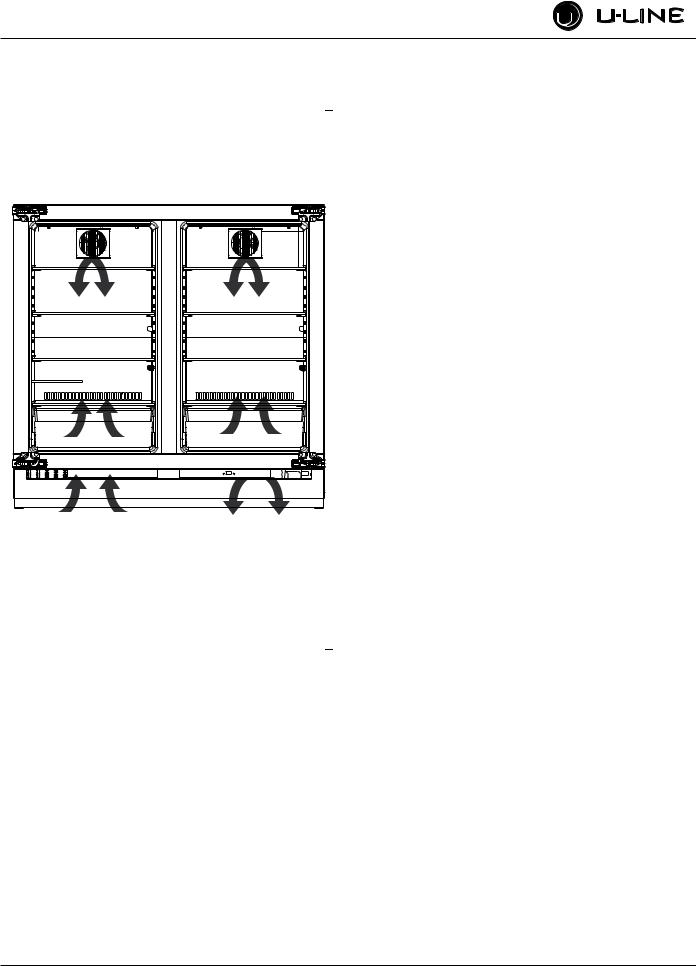
Interior Lighting
U-Line 3000 Series unit uses a state of the art theatre style LED lighting system.
Note: Lighting system is designed to fade in and out when switching states.
Up |
Zone Indicator |
Zone Toggle |
Zone Indicator |
Select |
|
|
|
|
U-SELECT LIGHTING |
|
|
LIGHTING |
LEVEL |
|
ON WITH DOOR |
HIGH |
|
3036 Model Display Shown |
|
|
|
|
Power |
Down |
U-Select Lighting |
|
1.To begin, press U-Select Lighting  to enter the lighting menu.
2.The unit initially defaults to control the lighting in both Zones simultaneously. To select a single zone press Zone Toggle  .
.
Notice the arrows on top of the display changing state. Pressing Zone Toggle  once will select the left side zone, pressing it again will select the right side zone, pressing it a third time will select both zones again.
3.Use Up  or Down
  to cycle through each available brightness setting; Low, Medium, or High.
4.Use U-Select Lighting  to cycle through each available timer setting. Selections include “On With Door”, “On 3 Hours”, “On 6 Hours”, or “On 24 Hours”.
1. To exit, press Select  or simply wait for the menu to time out.
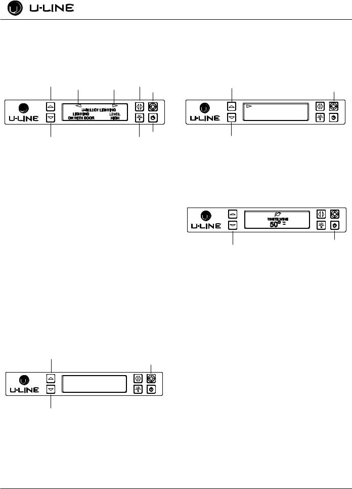
Customer Menu
The 3000 Series of U-Line undercounter refrigeration appliances contain a feature rich customer menu. The Customer Menu allows access to a series of advanced features including Energy Saver Mode, Sabbath mode, Actual Temp readings as well as a method to restore factory defaults.
1.To access the Customer Menu hold down both Up  and Select
 for 5 seconds.
2.Use Up  or Down
  to scroll through available selections.
Up
Select
WELCOME TO THE
CUSTOMER MENU. USE
UP/DOWN ARROWS TO
SCROLL SETTINGS.
Down
3.Use Select  to enter selected sub-menu.
4.To exit Customer menu, Use Down  to scroll to the bottom of the display and use Select
  to Select “Exit.”
Actual Temps
The Actual Temps option displays the actual temperature of each zone, evaporator, as well as ambient temperature.
1.To view Actual Temps first select Actual Temps from the customer menu.
Up
Select
RETURN TO MENU
ACTUAL TEMPS
LEFT ZONE = 38°F
RIGHT ZONE = 38°F
3036 Model Display Shown
Down
2.Use Up  or Down
  to scroll through available information.
3.To exit, Select  Return to Menu.
Energy Saver
Up |
Energy Saver Mode |
Select |
|||
|
|
Indicator |
|||
|
|
|
|
|
|
|
|
|
|
|
|
WHITE WINE
50O F


Power
Down
Energy Saver mode reduces overall energy consumption by altering user set point, differential, lighting and tone settings. When in Energy Saver mode a small leaf icon will be displayed on the main screen.
1.To enter Energy Saver first select Energy Saver from the Customer Menu.
2.Use Down  to select “Off” in the menu.
3.Press Select  .
.
4.Use Up  or Down
  to change the selection from Off to On.
5.Press Select  to confirm your selection.
6.To exit Energy Saver mode simply return to the Customer Menu, Select Energy Saver mode and change “On” to “Off”.
U-Line Service |
8 |
General Information
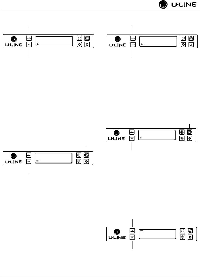
Sabbath Mode
Up
Select
RETURN TO MENU
SABBATH MODE
OFF
Down
The U-line 3000 Series of models offer a Sabbath mode for users who celebrate certain Sabbaths. Sabbath mode disables system responses to user initiated activities and all external functions; including lighting, display and audible alarms. The unit will still maintain internal temperatures and set points.
1.To enter Sabbath Mode, select Sabbath Mode from the Customer Menu.
2.Use Down  to select “Off”.
3.Press Select  , “Off” will begin to flash.
4.Use Up  or Down
  to change “Off” to “On”.
5.Press Select  to Confirm your selection.
The Display will fade out as the unit enters Sabbath Mode. Sabbath remains active until Power  is pushed.
Languages
Up
Select
RETURN TO MENU
LANGUAGES
ENGLISH
Down
The U-Line 3000 Series of models supports a number of Display Languages including English, Spanish, French and German.
To Change Display Language select Languages from the Customer Menu.
1.Use Down  to select “English”.
2.Press Select  , “English” will begin to flash.
3.Use Up  or Down
  to cycle through the available Languages.
4.Press Select  to confirm you choice.
Sound Level
Up
Select
RETURN TO MENU
SOUND LEVEL
HIGH
Down
Audible alarms and alert tones support four different Sound Level settings, High, Medium, Low, and Off.
To select a new sound level, enter the Sound Level menu from the Customer Menu.
1.Use Up  or Down
  to select the current sound level.
2.Press Select  , the current setting will begin to flash.
3.Use Up  or Down
  to select a different level.
4.Use Select  to confirm your choice.
Fahrenheit / Celsius
Up
Select
RETURN TO MENU
FARENHEIT/CELSIUS
DEGREES = °F
Down
Temperature and Set point information can be displayed in either Fahrenheit or Celsius.
To change from Fahrenheit to Celsius enter the Fahrenheit / Celsius menu from within the Customer Menu.
1.Use Down  to select “Degrees”.
2.Press Select  . The selection will begin to flash.
3.Use Up  or Down
  to select between °F (Fahrenheit) or °C (Celsius).
4.Press Select  to confirm your choice.
Factory Default
Up
Select
RETURN TO MENU
FACTORY DEFAULT
RESTORE?
Down
Factory Default will restore all settings to their factory default.
To access Factory Default
1. Use Down  to select “Factory Default”.
9 |
U-Line Service |
Loading...