


TRUE |
INSTALLATION MANUAL |
food service equipment, inc. |
SPEC SERIES®: STM |
CONGRATULATIONS!
You have just purchased the finest commercial refrigerator available. You can expect many years of trouble-free operation.
TABLE OF CONTENTS
SAFETY INFORMATION
Safety Precautions |
|
1 |
|
Proper Disposal, Connecting Electricity, & Adapter Plugs |
|
2 |
|
INSTALLATION
Ownership & Uncrating |
|
3 |
|||
How to Connect to Electricity & Wire Gauge Chart |
|
4 |
|||
Locating and Installation of Legs or Castors |
|
5 |
|||
Leveling & Sealing Cabinet to the Floor |
|
6 |
|||
SETUP
Standard Accessories |
|
7 |
|||||||
OPERATION |
STM1R-1S |
||||||||
|
|||||||||
Startup |
|
11 |
|||||||
Electronic Temperature Controls Sequence of Operation |
|
12 |
|||||||
MAINTENANCE, CARE, CLEANING |
|
||||||||
Cleaning Condenser Coil |
|
21 |
|||||||
Important Warranty Information |
|
22 |
|||||||
Stainless Steel Equipment Care and Cleaning |
|
23 |
|||||||
General Maintenance |
|
24 |
|||||||
WARRANTY |
|
||||||||
Warranty |
|
25 |
|||||||
STM2F-2S
INSTALLATION MANUAL
SPEC SERIES®: STM REFRIGERATOR/FREEZER
TRUE FOOD SERVICE EQUIPMENT, INC.
2001 East Terra Lane • O’Fallon, Missouri 63366-4434
(636)-240-2400 • FAX (636)-272-2408 • INT'L FAX (636)272-7546 • (800)-325-6152 Parts Department (800)-424-TRUE • Parts Department FAX# (636)-272-9471 Web: www.truemfg.com
#975529 • LM • 6/15

TRUE |
www.truemfg.com |
SPEC SERIES®: STM |
NOTICE TO CUSTOMER
Loss or spoilage of products in your refrigerator/ freezer is not covered by warranty. In addition to following recommended installation procedures you must run the refrigerator/freezer 24 hours prior to usage.
SAFETY INFORMATION
How to Maintain Your True Refrigerator to Receive the Most Efficient and Successful Operation.
You have selected one of the finest commercial refrigeration units made. It is manufactured under strict quality controls with only the best quality materials available.Your TRUE cooler when properly maintained will give you many years of trouble-free service.
WARNING: Use this appliance for its intended purpose as described in this Owner Manual.
TO LOCATE REFRIGERANT TYPE, SEE SERIAL LABEL INSIDE CABINET. This cabinet may contain fluorinated greenhouse gas covered by the Kyoto Protocol (please refer to cabinet’s inner label for type and volume, GWP of 134a= 1,300. R404a= 3,800).
FOR HYDROCARBON REFRIGERATION ONLY (R-290) SEE BELOW:
•DANGER - Risk of fire or explosion. Flammable refrigerant used. Do not use mechanical devices to defrost refrigerator. Do not puncture refrigerant tubing.
•DANGER - Risk of fire or explosion. Flammable refrigerant used. To be repaired only by trained service personnel. Do not puncture refrigerant tubing.
•CAUTION - Risk of fire or explosion. Flammable refrigerant used. Consult repair manual/owner’s guide before attempting to service this product. All safety precautions must be followed.
•CAUTION - Risk of fire or explosion. Dispose of properly in accordance with federal or local regulations. Flammable refrigerant used.
•CAUTION - Risk of fire or explosion due to puncture of refrigerant tubing; follow handling instructions carefully. Flammable refrigerant used.
•CAUTION - Keep clear of obstruction all ventilation openings in the appliance enclosure or in the structure for building-in.
SAFETY PRECAUTIONS
When using electrical appliances, basic safety precautions should be followed, including the following:
•This refrigerator must be properly installed and located in accordance with the Installation Instructions before it is used.
•Do not allow children to climb, stand or hang on the shelves in the refrigerator. They could damage the refrigerator and seriously injure themselves.
•Do not touch the cold surfaces in the freezer compartment when hands are damp or wet. Skin may stick to these extremely cold surfaces.
•Do not store or use gasoline or other flammable vapors and liquids in the vicinity of this or any other appliance. Do not store explosive substances such as aerosol cans with a flammable propellant in this appliance.
•Keep fingers out of the “pinch point” areas; clearances between the doors and between the doors and cabinet are necessarily small; be careful closing doors when children are in the area.
•Unplug the refrigerator before cleaning and making repairs.
•Setting temperature controls to the 0 position does not remove power to the light circuit, perimeter heaters, or evaporator fans.
NOTE: We strongly recommend that any servicing be preformed by a qualified technician.
1

TRUE |
www.truemfg.com |
SPEC SERIES®: STM |
DANGER!
RISK OF CHILD
ENTRAPMENT
PROPER DISPOSAL OF THE REFRIGERATOR
Child entrapment and suffocation are not problems of the past. Junked or abandoned refrigerators are still dangerous… even if they will sit for “just a few days.” If you are getting rid of your old refrigerator, please follow the instructions below to help prevent accidents.
BEFOREYOU THROW AWAYYOUR OLD
REFRIGERATOR OR FREEZER:
•Take off the doors.
•Leave the shelves in place so that children may not easily climb inside.
APPLIANCE DISPOSAL
When recycling appliance please make sure that the refrigerants are handled according to local and national codes, requirements and regulations.
REFRIGERANT DISPOSAL
Your old refrigerator may have a cooling system that uses “Ozone Depleting” chemicals. If you are throwing away your old refrigerator, make sure the refrigerant is removed for proper disposal by a qualified service technician. If you intentionally release any refrigerants you can be subject to fines and imprisonment under provisions of the environmental regulations.
USE OF EXTENSION CORDS
NEVER USE AN EXTENSION CORD! TRUE will not warranty any refrigerator that has been connected to an extension cord.
REPLACEMENT PARTS
•Component parts shall be replaced with like components.
•Servicing shall be done by authorized service personnel, to minimize the risk of possible ignition due to incorrect parts or improper service.
•Lamps must be replaced by identical lamps only.
•If the supply cord is damaged, it must be replaced by a special cord or assembly available from the manufacturer or its service agent.
WARNING!
HOW TO CONNECT ELECTRICITY
DO NOT, UNDER ANY CIRCUMSTANCES, CUT OR REMOVE THE GROUND PRONG FROM THE POWER CORD. FOR PERSONAL SAFETY, THIS APPLIANCE MUST BE PROPERLY GROUNDED.
The power cord from this appliance is equipped with a grounding plug which minimizes the possibility of electric shock hazard.
Have the wall outlet and circuit checked by a qualified electrician to make sure the outlet is properly grounded.
If the outlet is a standard 2-prong outlet, it is your personal responsibility and obligation to have it replaced with the properly grounded wall outlet.
The refrigerator should always be plugged into it’s own individual electrical circuit, which has a voltage rating that matches the rating plate.
This provides the best performance and also prevents overloading building wiring circuits which could cause a fire hazard from overheated wires.
Never unplug your refrigerator by pulling on the power cord. Always grip plug firmly and pull straight out from the outlet.
Repair or replace immediately all power cords that have become frayed or otherwise damaged. Do not use a cord that shows cracks or abrasion damage along its length or at either end.
When removing the refrigerator away from the wall, be careful not to roll over or damage the power cord.
If supply power cord is damaged it should be replaced with original equipment manufacture parts. To avoid hazard this should be done by a qualified service technician.
USE OF ADAPTER PLUGS
NEVER USE AN ADAPTER PLUG! Because of potential safety hazards under certain conditions, we strongly recommend against the use of an adapter plug.
The incoming power source to the cabinet including any adapters used must have the adequate power available and must be properly grounded. Only adapters listed with UL should be used.
NORTH AMERICA USE ONLY!
NEMA plugs
TRUE uses these types of plugs. If you do not have the right outlet have a certified electrician install the correct power source.
NOTE: International plug configurations vary by voltage and country.
115/60/1 |
115/208-230/1 |
115/60/1 |
|
208-230/60/1 |
NEMA-5-15R |
NEMA-14-20R |
NEMA-5-20R |
|
NEMA-6-15R |
2
TRUE |
www.truemfg.com |
SPEC SERIES®: STM |
INSTALLATION
OWNERSHIP
To ensure that your unit works properly from the first day, it must be installed properly. We highly recommend a trained refrigeration mechanic and electrician install your TRUE equipment. The cost of a professional installation is money well spent.
Before you start to install your TRUE unit, carefully inspect it for freight damage. If damage is discovered, immediately file a claim with the delivery freight carrier.
TRUE is not responsible for damage incurred during shipment.
UNCRATING
TOOLS REQUIRED
•Adjustable Wrench
•1/2 inch socket (Castor Bolts)
•3/4 inch socket (Skid Bolts)
•Level
The following procedure is recommended for uncrating the unit:
A.Remove the outer packaging, (cardboard and bubbles or Styrofoam corners and clear plastic). Inspect for concealed damage. Again, immediately file a claim with the freight carrier if there is damage.
B.Move your unit as close to the final location as possible before removing the wooden skid.
NOTE: KEYS FOR COOLERS WITH DOOR LOCKS ARE LOCATED IN WARRANTY PACKETS.
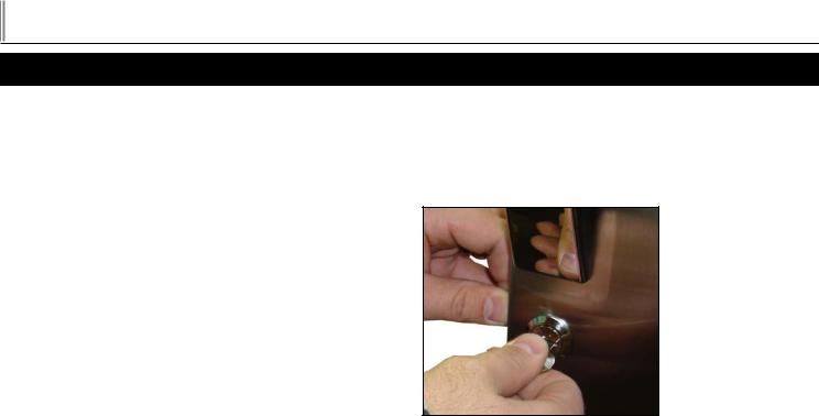
LOCK AND KEYS
The following procedure is for locking and unlock unit:
A.Insert the key and turn.
B.Remove the key.
Insert key
3

TRUE |
www.truemfg.com |
SPEC SERIES®: STM |
HOW TO CONNECT ELECTRICITY
Do not, under any circumstances, cut or remove the ground prong from the power cord. For personal safety, this appliance must be properly grounded.
The power cord of this appliance is equipped with a grounding plug which mates with a standard grounding wall outlet to minimize the possibility of electric shock hazard from this appliance. Have the wall outlet and circuit checked by a qualified electrician to make sure the outlet is properly grounded. If the outlet is a standard 2-prong outlet, it is your personal responsibility and obligation to have it replaced with the properly grounded wall outlet. The unit should always be plugged into its own individual electrical circuit, which has a voltage rating that matches the rating plate. This provides the best performance and also prevents overloading building wiring circuits which could cause a fire hazard from overheated wires. Never unplug your unit by pulling on the power cord. Always grip plug firmly and pull straight out from the outlet. Repair or replace immediately all power cords that have become frayed or otherwise damaged. Do not use a cord that shows cracks or abrasion damage along its length or at either end. When removing the unit away from the wall, be careful not to roll over or damage the power cord.
ELECTRIC INSTALLATION & SAFETY INFORMATION
•If the supply cord is damaged, it must be replaced by a special cord or assembly available from the manufacturer or its service agent.
•Lamps must be replaced by identical lamps only.
•Appliance tested according to the climate classes 5 and 7 temperature and relative humidity.
ELECTRICAL INSTRUCTIONS
A.Before your new unit is connected to a power supply, check the incoming voltage with a voltmeter. If anything less than 100% of the rated voltage for operation is noted, correct immediately.
B.All units are equipped with a service cord, and must be powered at proper operating voltage at all times. Refer to cabinet data plate for this voltage.
TRUE RECOMMENDS THAT A SOLE USE CIRCUIT BE DEDICATED FOR THE UNIT.
WARNING: Compressor warranties are void if compressor burns out due to low voltage.
WARNING: Power supply cord ground should not be removed!
WARNING: Do not use electrical appliances inside the food storage compartments of the appliances unless they are of the type recommended by the manufacturer.
NOTE: To reference wiring diagram, remove front louvered grill, wiring diagram is positioned on the inside cabinet wall.
WIRE GAUGE CHART
115 Volts |
|
Distance In Feet To Center of Load |
|
|
||||||||
Amps |
20 |
30 |
40 |
50 |
60 |
70 |
80 |
90 |
100 120 140 160 |
|||
2 |
14 |
14 |
14 |
14 |
14 |
14 |
14 |
14 |
14 |
14 |
14 |
14 |
3 |
14 |
14 |
14 |
14 |
14 |
14 |
14 |
14 |
14 |
14 |
14 |
12 |
4 |
14 |
14 |
14 |
14 |
14 |
14 |
14 |
14 |
14 |
12 |
12 |
12 |
5 |
14 |
14 |
14 |
14 |
14 |
14 |
14 |
12 |
12 |
12 |
10 |
10 |
6 |
14 |
14 |
14 |
14 |
14 |
14 |
12 |
12 |
12 |
10 |
10 |
10 |
7 |
14 |
14 |
14 |
14 |
14 |
12 |
12 |
12 |
10 |
10 |
10 |
8 |
8 |
14 |
14 |
14 |
14 |
12 |
12 |
12 |
10 |
10 |
10 |
8 |
8 |
9 |
14 |
14 |
14 |
12 |
12 |
12 |
10 |
10 |
10 |
8 |
8 |
8 |
10 |
14 |
14 |
14 |
12 |
12 |
10 |
10 |
10 |
10 |
8 |
8 |
8 |
12 |
14 |
14 |
12 |
12 |
10 |
10 |
10 |
8 |
8 |
8 |
8 |
6 |
14 |
14 |
14 |
12 |
10 |
10 |
10 |
8 |
8 |
8 |
6 |
6 |
6 |
16 |
14 |
12 |
12 |
10 |
10 |
8 |
8 |
8 |
8 |
6 |
6 |
6 |
18 |
14 |
12 |
10 |
10 |
8 |
8 |
8 |
8 |
8 |
8 |
8 |
5 |
20 |
14 |
12 |
10 |
10 |
8 |
8 |
8 |
6 |
6 |
6 |
5 |
5 |
25 |
12 |
10 |
10 |
8 |
8 |
6 |
6 |
6 |
6 |
5 |
4 |
4 |
30 |
12 |
10 |
8 |
8 |
6 |
6 |
6 |
6 |
5 |
4 |
4 |
3 |
35 |
10 |
10 |
8 |
6 |
6 |
6 |
5 |
5 |
4 |
4 |
3 |
2 |
40 |
10 |
8 |
8 |
6 |
6 |
5 |
5 |
4 |
4 |
3 |
2 |
2 |
45 |
10 |
8 |
6 |
6 |
6 |
5 |
4 |
4 |
3 |
3 |
2 |
1 |
50 |
10 |
8 |
6 |
6 |
5 |
4 |
4 |
3 |
3 |
2 |
1 |
1 |
230 Volts |
|
Distance In Feet To Center of Load |
|
|
||||||||
Amps |
20 |
30 |
40 |
50 |
60 |
70 |
80 |
90 |
100 120 140 160 |
|||
5 |
14 |
14 |
14 |
14 |
14 |
14 |
14 |
14 |
14 |
14 |
14 |
14 |
6 |
14 |
14 |
14 |
14 |
14 |
14 |
14 |
14 |
14 |
14 |
14 |
12 |
7 |
14 |
14 |
14 |
14 |
14 |
14 |
14 |
14 |
14 |
14 |
12 |
12 |
8 |
14 |
14 |
14 |
14 |
14 |
14 |
14 |
14 |
14 |
12 |
12 |
12 |
9 |
14 |
14 |
14 |
14 |
14 |
14 |
14 |
14 |
12 |
12 |
12 |
10 |
10 |
14 |
14 |
14 |
14 |
14 |
14 |
14 |
12 |
12 |
12 |
10 |
10 |
12 |
14 |
14 |
14 |
14 |
14 |
14 |
12 |
12 |
12 |
10 |
10 |
10 |
14 |
14 |
14 |
14 |
14 |
14 |
12 |
12 |
12 |
10 |
10 |
10 |
8 |
16 |
14 |
14 |
14 |
14 |
12 |
12 |
12 |
10 |
10 |
10 |
8 |
8 |
18 |
14 |
14 |
14 |
12 |
12 |
12 |
10 |
10 |
10 |
8 |
8 |
8 |
20 |
14 |
14 |
14 |
12 |
10 |
10 |
10 |
10 |
10 |
8 |
8 |
8 |
25 |
14 |
14 |
12 |
12 |
10 |
10 |
10 |
10 |
8 |
8 |
6 |
6 |
30 |
14 |
12 |
12 |
10 |
10 |
10 |
8 |
8 |
8 |
6 |
6 |
6 |
35 |
14 |
12 |
10 |
10 |
10 |
8 |
8 |
8 |
8 |
6 |
6 |
5 |
40 |
14 |
12 |
10 |
10 |
8 |
8 |
8 |
6 |
6 |
6 |
5 |
5 |
50 |
12 |
10 |
10 |
8 |
6 |
6 |
6 |
6 |
6 |
5 |
4 |
4 |
60 |
12 |
10 |
8 |
6 |
6 |
6 |
6 |
6 |
5 |
4 |
4 |
3 |
70 |
10 |
10 |
8 |
6 |
6 |
6 |
5 |
5 |
4 |
4 |
2 |
2 |
80 |
10 |
8 |
8 |
6 |
6 |
5 |
5 |
4 |
4 |
3 |
2 |
2 |
90 |
10 |
8 |
6 |
6 |
5 |
5 |
4 |
4 |
3 |
3 |
1 |
1 |
100 |
10 |
8 |
6 |
6 |
5 |
4 |
4 |
3 |
3 |
2 |
1 |
1 |
4

TRUE |
www.truemfg.com |
SPEC SERIES®: STM |
LOCATING
1.Make sure unit is as close to the final location as possible.
2.Remove the shipping bolts located at the bottom of the wooden skid.
3.Carefully slide the unit off the wooden skid. Slide packing material underneath the side of the unit hanging off the skid. Then install castors or legs for that side of the unit.
4.Then carefully slide the other side of the unit off one corner at a time while installing castors or legs for each corner. Use packing material for under each corner of the unit before
installing a castor or leg. |
Removing shipping bolts |
INSTALLATION OF CASTORS OR OPTIONAL LEGS
Important Safeguard for installation of leg/castor. Images 1-5 demonstrate procedure.
SECURING CASTORS AND LEGS
To obtain maximum strength and stability of the unit, it is important that you make sure each castor is secure. Optional legs are handtightened securely against the lower rail assembly. The bearing race on the castor or the top edge of the leg must make firm contact with the rail.
LEVELING SHIMS
Four leveling shims have been provided for leveling castored units positioned on uneven floors. Shims must be positioned between rail end and bearing race.
A.Turn the bearing race counter-clockwise until the cabinet is level. Level front to back and side to side. (diagonally)
B.Install the desired number of shims, making sure the slot of the shim is in contact with the threaded stem of the castor.
C.If more than one shim is used, turn the slot at a 90° angle so they are not in line.
D.Turn the bearing race clockwise to tighten and secure the castor by tightening the anchoring bolt with a 3/4 inch openend wrench or the tool provided.
CAUTION: TO AVOID DAMAGE TO LOWER RAIL ASSEMBLY, SLOWLY RAISE UNIT TO UPRIGHT POSITION.
NOTE: OPEN HOLES LOCATED ON THE CROSS MEMBERS OF THE FRAME RAIL SHOULD BE PLUGGED BEFORE UNIT IS IN USE.
|
|
|
|
|
1 |
|
|
2 |
|
Slide packing material under the unit. Anchor castor.
|
|
|
|
|
3 |
|
|
4 |
|
Thread leg into cabinet bottom |
|
The end of the leg is adjustable for |
||
cabinet. |
|
easy leveling. |
||
5
Castor with leveling shims.
5

TRUE |
www.truemfg.com |
SPEC SERIES®: STM |
LEVELING SEALING CABINET TO FLOOR
A.Set unit in its final location. Be sure there is adequate ventilation STEP 1 - Position Cabinet - Allow one inch between the wall and in your room. Under extreme heat conditions, (100°F+, rear of the refrigerator to assure proper ventilation. For freezers 3
38°C+), you may want to install an exhaust fan.
WARNING: WARRANTY IS VOID IF VENTILATION IS INSUFFICIENT.
B.Proper leveling of your TRUE cooler is critical to operating success (for non-mobile models). Effective condensate removal and door operation will be effected by leveling.
C.The cooler should be leveled front to back and side to side with a level.
D.Ensure that the drain hose or hoses are positioned in the pan.
E.Free plug and cord from inside the lower rear of the cooler (do not plug in).
F.The unit should be placed close enough to the electrical supply so that extension cords are never used.
G.Applicance tested according to the climate classes 5 and 7 for temperature and relative humidity.
WARNING: CABINET WARRANTIES ARE VOID IF OEM POWER CORD IS TAMPERED WITH.TRUE WILL NOT WARRANTY ANY UNITS THAT ARE CONNECTED TO AN EXTENSION CORD.
inches between the wall and rear of the cabinet will assure proper ventilation.
STEP 2 - Level Cabinet - Cabinet should be level, side to side and front to back. Place a carpenter’s level in the interior floor in four places:
A.Position level in the inside floor of the unit near the doors. (Level should be parallel to cabinet front). Level cabinet.
B.Position level at the inside rear of cabinet. (Again level should be placed parallel to cabinet back).
C.Perform similar procedures to steps A & B by placing the level on inside floor (left and right sides - parallel to the depth of the cooler). Level cabinet.
STEP 3 - Draw an outline on the base on the floor.
STEP 4 - Raise and block the front side of the cabinet.
STEP 5 - Apply a bead of “NSF Approved Sealant”, (see list below), to floor on half inch inside the outline drawn.The bead must be heavy enough to seal the entire cabinet surface when it is down on the sealant.
STEP 6 - Raise and block the rear of the cabinet
STEP 7 - Apply sealant on floor as outlined in Step 5 on other three sides.
STEP 8 - Examine to see that cabinet is sealed to floor around entire perimeter.
NOTE: Asphalt floors are very susceptible to chemical attack. A layer of tape on the floor prior to applying the sealant will protect the floor.
NSF APPROVED SEALANTS:
1.Minnesota Mining #ECU800 Caulk
2.Minnesota Mining #ECU2185 Caulk
3.Minnesota Mining #ECU1055 Bead
4.Minnesota Mining #ECU1202 Bead
5.Armstrong Cork - Rubber Caulk
6.Products Research Co. #5000 Rubber Caulk
7.G.E. Silicone Sealer
8.Dow Corning Silicone Sealer
6
TRUE |
www.truemfg.com |
SPEC SERIES®: STM |
SETUP
STANDARD ACCESSORIES
PILASTER INSTALLATION & OPERATION
TRUE STR, STA, and STG cabinets are available with four different shelving / tray slide options.
Type Kit #1. Angle Type Tray Slide
Type Kit #2. Rod Style Tray Slide
Type Kit #3. Universal Tray Slide
Type Kit #4. Shelf Standards (shelf clips)
REQUIRED TOOLS:
•Standard Screwdriver (Flathead)
•Rubber / Plastic Mallet
•Tape Measure
INSTALLATION PROCEDURES (WIRE SHELVES):
Wire shelves come with shelf clips (image 1).
Properly insert the shelf clips in the desired height (remember all shelf clips will need to be installed at the same height to keep the shelf level.)
Once the shelves are installed the remaining threaded holes will have thumb screws inserted. These thumb screws are provided in the unit.
Shelf |
Standards |
Shelf |
Shelf |
Shelf |
Clip |
Type Kit #4 (Shelf Standards / Shelf Clips)
WARNING!
Do not use pliers or any crimping tools when installing shelf clips. Altering shelf clips in any way can lead to shelving instability.
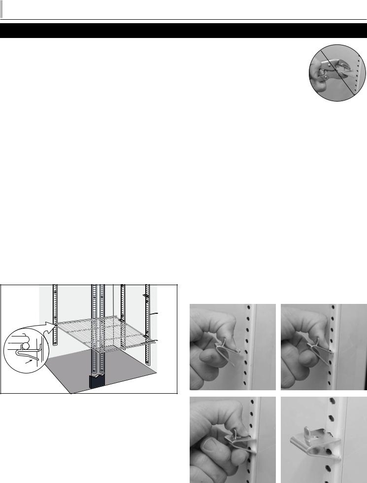
SHELF INSTALLATION:
For Proper Shelf Clip Installation Please Read The Following
Instructions.
STEP 1
Install the top tab of the shelf clip into the proper hole. Push up on the bottom of the clip. (See image 1).
STEP 2
Bottom tab of the shelf clip will fit tightly.You may need to squeeze or twist the bottom of the shelf clip to install. (See image 2 & 3).
STEP 3
After installation, the shelf clip will fit snug into the shelf standard. The shelf clip should not be loose or able to wiggle out of the shelf standard.
SHELF INSTALLATION TIPS
1.Install all the shelf clips before installing the shelves.
2.Start at the bottom in terms of shelf installation and work your way up.
3.Always lay the back of each shelf down on the rear clips before the front.
|
|
|
|
|
1 |
|
|
2 |
|
|
|
|
|
|
3 |
|
|
4 |
|
7
 Loading...