

Page 1

User Guide
Easy Smart Switch
TL-SG105E/TL-SG108E/TL-SG108PE/TL-SG116E
TL-SG1016PE/TL-SG1016DE/TL-SG1024DE
1910012686 REV5.0.0
December 2019
Page 2

CONTENTS
About This Guide
Intended Readers ................................................................................................................................................................1
Conventions ...........................................................................................................................................................................1
More Information .................................................................................................................................................................1
Introduction
Product Overview ................................................................................................................................................................ 4
Logging Into the Switch .....................................................................................................................................................5
Managing System
System ..................................................................................................................................................................................... 8
Overview .........................................................................................................................................................................................................8
Supported Features .................................................................................................................................................................................8
Configuring System Info ...................................................................................................................................................9
Viewing the System Information .......................................................................................................................................................9
Specifying the Device Description ..................................................................................................................................................9
Configuring IP ..................................................................................................................................................................... 10
Configuring LED (Only for Certain Devices) ............................................................................................................ 12
Configuring User Account ............................................................................................................................................. 13
Backing up and Restoring the Switch ....................................................................................................................... 14
Saving the Current Configuration ..................................................................................................................................................14
Restoring to the Previous Configuration ...................................................................................................................................15
Rebooting the Switch ...................................................................................................................................................... 17
Resetting the Switch ........................................................................................................................................................ 18
Upgrading the Firmware ................................................................................................................................................. 19
Appendix: Default Parameters ..................................................................................................................................... 21
Switching
Switching .............................................................................................................................................................................. 23
Overview ......................................................................................................................................................................................................23
Supported Features ..............................................................................................................................................................................23
Configuring Ports .............................................................................................................................................................. 25
Configuring IGMP Snooping ......................................................................................................................................... 27
Configuring LAG ................................................................................................................................................................ 28
Page 3

Configuration Examples ................................................................................................................................................. 30
Example for Configuring IGMP Snooping .................................................................................................................................30
Network Requirements ..........................................................................................................................................................30
Configuration Scheme ...........................................................................................................................................................30
Configuration Steps ................................................................................................................................................................31
Example for Configuring LAG ..........................................................................................................................................................32
Network Requirements ..........................................................................................................................................................32
Configuration Steps ................................................................................................................................................................33
Appendix: Default Parameters ..................................................................................................................................... 34
Monitoring
Monitoring ........................................................................................................................................................................... 36
Overview ......................................................................................................................................................................................................36
Supported Features ..............................................................................................................................................................................36
Viewing Port Statistics .................................................................................................................................................... 37
Configuring Port Mirror ................................................................................................................................................... 39
Testing Cables ................................................................................................................................................................... 41
Configuring Loop Prevention ....................................................................................................................................... 43
Appendix: Default Parameters ..................................................................................................................................... 44
Configuring VLAN
Overview .............................................................................................................................................................................. 46
Configuring MTU VLAN................................................................................................................................................... 48
Configuring Port Based VLAN ...................................................................................................................................... 49
Configuring 802.1Q VLAN ............................................................................................................................................. 50
Configuring the VLAN ..........................................................................................................................................................................50
Configuring the PVID ............................................................................................................................................................................52
Configuration Example for 802.1Q VLAN ................................................................................................................ 53
Network Requirements ........................................................................................................................................................................53
Configuration Scheme ........................................................................................................................................................................53
Configuration Steps ..............................................................................................................................................................................55
Appendix: Default Parameters ..................................................................................................................................... 59
Configuring QoS
QoS ......................................................................................................................................................................................... 61
Overview ......................................................................................................................................................................................................61
Supported Features ..............................................................................................................................................................................61
Page 4

Configuring Basic QoS ................................................................................................................................................... 62
Configuring QoS in Port Based Mode .........................................................................................................................................63
Configuring QoS in 802.1P Based Mode ..................................................................................................................................64
Configuring QoS in DSCP/802.1P Based Mode ...................................................................................................................64
Configuring Bandwidth Control ................................................................................................................................... 65
Configuring Storm Control ............................................................................................................................................ 67
Configuration Example for Basic QoS....................................................................................................................... 69
Network Requirements ........................................................................................................................................................................69
Configuration Scheme ........................................................................................................................................................................69
Configuration Steps ..............................................................................................................................................................................70
Appendix: Default Parameters ..................................................................................................................................... 72
Configuring PoE
Overview .............................................................................................................................................................................. 74
Configuring PoE................................................................................................................................................................. 75
Configuring PoE Auto Recovery ................................................................................................................................. 77
Appendix: Default Parameters ..................................................................................................................................... 79
(Only for Certain Devices)
Page 5

About This Guide Intended Readers
About This Guide
This Configuration Guide provides information for configuring the Easy Smart Switch via
the web interface. Read this guide carefully before operation.
You can also configure the switch using the Easy Smart Configuration Utility. For more
information, refer to the Easy Smart Configuration Utility User Guide. Go to the website
https://www.tp-link.com/support
find this guide on the product Support web page.
Intended Readers
This Guide is intended for network managers familiar with IT concepts and network
terminologies.
, search the model number of your switch, and you can
Conventions
When using this guide, notice that features available in Easy Smart Switch may vary by
model and software version. The availability of Easy Smart Switch may also vary by region
or ISP. All images, steps, and descriptions in this guide are only examples and may not
reflect your actual experience. Throughout the guide, we will take TL-SG1016PE as the
switch to be configured for example.
Some models featured in this guide may be unavailable in your country or region. For local
sales information, visit
The information in this document is subject to change without notice. Every effort has
been made in the preparation of this document to ensure accuracy of the contents, but
all statements, information and recommendations in this document do not constitute
the warranty of any kind, express or implied. Users must take full responsibility for their
application of any products.
In this Guide, the following conventions are used:
PoE budget calculations are based on laboratory testing. Actual PoE power budget is not
guaranteed and will vary as a result of client limitations and environmental factors.
https://www.tp-link.com
.
The symbol
make better use of your device.
Menu Name > Submenu Name > Tab page indicates the menu structure. SYSTEM >
System Info > System Summary means the System Summary page under the System Info
menu option that is located under the SYSTEM menu.
Bold font indicates a button, toolbar icon, menu or menu item.
stands for
Note
. Notes contain suggestions or references that help you
User Guide 1
Page 6

About This Guide More Information
More Information
■
The latest software and documentations can be found at Download Center at
https://www.tp-link.com/support
■
The Installation Guide (IG) can be found where you find this guide or inside the package
of the switch.
■
Specifications can be found on the product page at
■
To ask questions, find answers, and communicate with TP-Link users or engineers,
please visit
■
Our Technical Support contact information can be found at the Contact Technical
Support page at
https://community.tp-link.com
https://www.tp-link.com/support
.
https://www.tp-link.com
to join TP-Link Community.
.
.
User Guide 2
Page 7

Part 1
Introduction
CHAPTERS
1. Product Overview
2. Logging Into the Switch
Page 8

Introduction Product Overview
1
Product Overview
Easy Smart Switch is an ideal upgrade from Unmanaged Switch, designed for Small Office
and Home Office networks. The switch supports the following features:
■ Traffic monitoring: Port mirroring, loop prevention and cable test enable the
administrator to monitor traffic of the network effectively.
■ VLAN: MTU VLAN, Port based VLAN and 802.1Q VLAN can restrict broadcast domain,
enhance network security and help manage devices easily.
■ QoS: Port based QoS, 802.1P based QoS and DSCP/802.1P based QoS optimize
traffic on your business network, and keep latency-sensitive traffic moving smoothly.
Bandwidth control helps distribute and utilize network bandwidth reasonably. Storm
control helps avoid network broadcast storm.
■ PoE: PoE (Power over Ethernet) is a remote power supply function. With this function,
the switch can supply power to the connected devices over twisted-pair cables.
Note:
TL-SG108PE and TL-SG1016PE support the PoE feature, but only TL-SG1016PE supports PoE
configurations.
User Guide 4
Page 9

Introduction Logging Into the Switch
2
Logging Into the Switch
To configure your switch through a web browser on your PC, follow these steps:
1) Connect your switch to the network and connect your PC to the switch.
2) Find out the IP address of the switch.
■ By default, the switch receives an IP address from a DHCP server (or a router that
functions as a DHCP server) in your network. You can find out this IP address on the
DHCP server.
■ If the switch cannot receive an IP address from a DHCP server, it uses the static IP
address of 192.168.0.1, with a subnet mask of 255.255.255.0.
3) Configure IP address on your PC to make sure the switch and PC are in the same
subnet.
■ If the switch uses an IP address assigned by a DHCP server, set your PC to obtain an
IP address automatically from the DHCP server.
■ If the switch uses the static IP address of 192.168.0.1, configure your PC’s
IP address as 192.168.0.x (”x” ranges from 2 to 254), and subnet mask as
255.255.255.0.
4) Launch a web browser on your PC. The supported web browsers include, but are not
limited to, the following types:
■ IE 8.0, 9.0, 10.0, 11.0
■ Firefox 26.0, 27.0
■ Chrome 32.0, 33.0
5) In the address bar of the web browser, enter the IP address of the switch. Here we
suppose the switch uses the static IP address 192.168.0.1.
Figure 2-1 Entering the IP Address of the Switch in the Browser
User Guide
5
Page 10

Introduction Logging Into the Switch
6) Enter the username and password in the pop-up login window. Enter admin for both
username and password in lower case letters.
Figure 2-2 Logging Into the Switch
Note:
The first time you log in, change the password to better protect your network and devices.
7) The typical web interface displays below. You can view the running status of the switch
and configure the switch on this interface.
Figure 2-3 Launching the Web Interface
User Guide 6
Page 11

Part 2
Managing System
CHAPTERS
1. System
2. Configuring System Info
3. Configuring IP
4. Configuring LED (Only for Certain Devices)
5. Configuring User Account
6. Backing up and Restoring the Switch
7. Rebooting the Switch
8. Resetting the Switch
9. Upgrading the Firmware
10. Appendix: Default Parameters
Page 12

Managing System System
1
System
1.1 Overview
In System module, you can view the system information and configure the system
parameters and features of the switch.
1.2 Supported Features
System Info
The System Info is mainly used to view the system information and configure the device
description.
IP Setting
Each device in the network possesses a unique IP address. You can access the switch
using IP address of the switch. You can set IP address of the switch manually or using
DHCP.
User Account Management
User Account Management is mainly used to modify the administrator’s username and
password in order to refuse illegal users.
Backup and Restore
Backup and Restore is used to download the current configuration and save it as a file
to your computer, and upload a backup configuration file to restore your switch to the
previous configuration.
System Reboot
System Reboot is used to reboot the switch.
System Reset
System Reset is used to reset the switch to the factory default setting. All the settings will
be cleared after the switch is reset.
Firmware Upgrade
To upgrade the firmware is to get more functions and better performance. Go to the
website
https://www.tp-link.com
to download the updated firmware.
User Guide 8
Page 13

Managing System Configuring System Info
2
Configuring System Info
With system information configuration, you can:
■
View the system information
■
Specify the device description
2.1 Viewing the System Information
Choose the menu System > System Info to load the following page. You can view the basic
system information of the switch.
Figure 2-1 Viewing the System Summary
2.2 Specifying the Device Description
Choose the menu System > System Info to load the following page. Specify a new device
description for the switch, and click Apply.
Figure 2-2 Specifying the Device Description
User Guide
9
Page 14

Managing System Configuring IP
3
Configuring IP
You can configure the system IP address in the following two ways:
■ Configure the System IP Address Using DHCP
■ Configure the System IP Address Manually
Configuring the System IP Address Using DHCP
Choose the menu System > IP Setting to load the following page.
Figure 3-1 Configuring System IP Address Using DHCP
Follow these steps to configure the system IP address using DHCP:
1) Select DHCP setting as Enable from the drop-down list .
2) Click Apply. The switch will obtain IP settings from the DHCP server.
Configuring the System IP Address Manually
Choose the menu System > IP Setting to load the following page.
Figure 3-2 Configuring System IP Address Manually
Follow these steps to configure the system IP address manually:
1) Select DHCP setting as Disable from the drop-down list.
2) Specify the IP address, subnet mask and default gateway.
IP Address Specify the system IP of the switch. You can use this IP address to access
the switch.
User Guide 10
Page 15

Managing System Configuring IP
Subnet Mask Specify the subnet mask of the switch..
Default Gateway Specify the default gateway of the switch.
3) Click Apply.
User Guide
11
Page 16
Managing System Configuring LED (Only for Certain Devices)
4
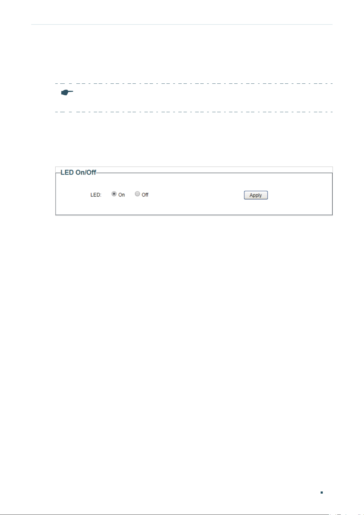
Configuring LED (Only for Certain Devices)
Note:
TL-SG116E does not support LED On/Off.
With this function, you can turn on or turn off the LED with one click.
Choose the menu System > LED On/Off to load the following page. Choose the LED status
and click Apply.
Figure 4-1 Configuring LED On/Off
User Guide 12
Page 17
Managing System Configuring User Account
5
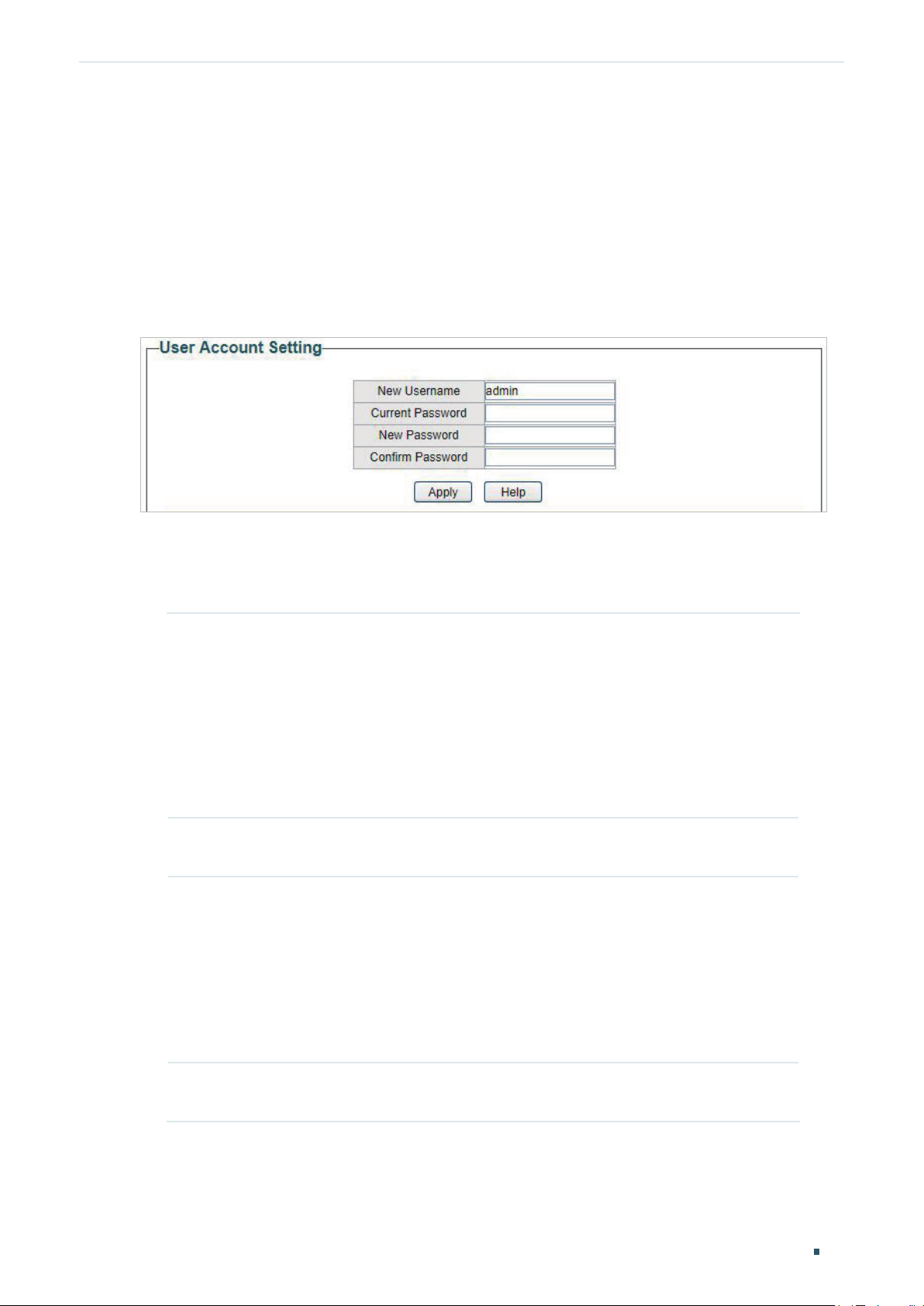
Configuring User Account
With user account management, you can modify the administrator’s username and
password in order to refuse illegal users.
Choose the menu System > User Account to load the following page.
Figure 5-1 Configuring User Account
Follow these steps to configure the user account:
1) Specify the new username, enter the current password, specify a new password and
confirm the new password.
New Username Create a user name for login.
For TL-SG105E, TL-SG108E, and TL-SG108PE:
The user name should be no more than 16 characters using digits, letters
and underlines only.
For TL-SG116E, TL-SG1016PE, TL-SG1016DE and TL-SG1024DE:
The user name should be less than 16 characters and no spaces are
allowed.
Current
Password
New Password Specify a new password for login.
Enter the current password of the switch. By default, the password is
admin.
For TL-SG105E, TL-SG108E, and TL-SG108PE:
The password should be 6–16 characters using digits, letters and
underlines only.
For TL-SG116E, TL-SG1016PE, TL-SG1016DE and TL-SG1024DE:
The password should be 6–16 characters and no spaces are allowed.
Confirm
Password
2) Click Apply.
Retype the new password.
User Guide
13
Page 18

Managing System Backing up and Restoring the Switch
6
Backing up and Restoring the Switch
With backup and restore, you can:
■ Save the current configuration.
■ Restore to the previous configuration.
6.1 Saving the Current Configuration
Choose the menu System > System Tools > Backup and Restore to load the following
page. In the Config Backup section, click Backup Config to save the configuration file to
your PC.
Figure 6-1 Backing Up the Configuration
Note:
It will take several minutes to save the configuration file. Wait without any operation.
User Guide 14
Page 19

Managing System Backing up and Restoring the Switch
6.2 Restoring to the Previous Configuration
Choose the menu System > System Tools > Backup and Restore to load the following
page.
Figure 6-2 Restoring the Configuration
Follow these steps to restore the switch to the previous configuration:
1) In the Config Restore section, click Choose File to load the following page. Specify the
configuration file path and select the configuration file.
Figure 6-3 Choosing the Configuration File
User Guide
15
Page 20

Managing System Backing up and Restoring the Switch
2) Click Open and the following page will be displayed. In the Config Restore section, click
Restore Config to restore the switch to the previous configuration. It will take effect
after the switch automatically reboots.
Figure 6-4 Restoring to the Previous Configuration
Note:
● It will take several minutes to restore the configuration. Wait without any operation.
● To avoid any damage, do not power down the switch while being restored.
● After being restored, the current configuration of the switch will be lost.
User Guide 16
Page 21

Managing System Rebooting the Switch
7
Rebooting the Switch
Choose the menu System > System Tools > System Reboot to load the following page.
Click Reboot.
Figure 7-1 Rebooting the Switch
Note:
● It will take several minutes to reboot the switch. Wait without any operation while the switch
reboots.
● To avoid any damage, do not power down the switch while the switch reboots.
User Guide
17
Page 22
Managing System Resetting the Switch
8
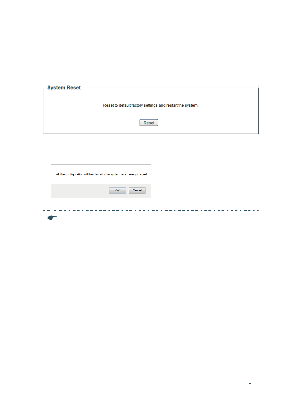
Resetting the Switch
Choose the menu System > System Tools > System Reset to load the following page.
Figure 8-1 Resetting the Switch
Follow these steps to reset the switch.
1) Click Reset, and the following page will pop up.
Figure 8-2 Being Sure to Reset the Switch
2) Click OK to reset the switch.
Note:
● After the switch is reset, it will reboot automatically.
● It will take several minutes to reboot the switch. Wait without any operation while the switch
reboots.
● To avoid any damage, do not power down the switch during the reset.
● After the switch is reset, all the settings will be restored to the default.
User Guide 18
Page 23

Managing System Upgrading the Firmware
9
Upgrading the Firmware
Choose the menu System > System Tools > Firmware Upgrade to load the following
page.
Figure 9-1 Being Ready to Upgrade the Firmware
Follow these steps to upgrade the firmware:
1) Click Choose File to load the following page. Specify the firmware file path and select
the firmware to upgrade.
Figure 9-2 Browsing the Firmware File
User Guide
19
Page 24

Managing System Upgrading the Firmware
2) Click Open and the following page will be displayed. Click Upgrade.
Figure 9-3 Upgrading the Firmware
Note:
● It will take several minutes to upgrade the firmware. Wait without any operation.
● Select the proper software version matching with the hardware to upgrade.
● To avoid damage, do not power down the switch while upgrading the firmware.
● It is recommended to backup the configuration before upgrading.
User Guide 20
Page 25

Managing System Appendix: Default Parameters
10
Default settings of System Info are listed in the following table.
Table 10-1 Default Settings of System Info
Parameter Default Setting
Device Description The model name
Default settings of IP Setting are listed in the following table.
Table 10-2 Default Settings of IP Address Configuration
Parameter Default Setting
DHCP Setting Enable
IP Address 192.168.0.1
Subnet Mask 255.255.255.0
Default Gateway 0.0.0.0
Appendix: Default Parameters
of the switch.
Default settings of User Account are listed in the following table.
Table 10-3 Default Settings of User Account Configuration
Parameter Default Setting
New Username admin
User Guide
21
Page 26

Part 3
Switching
CHAPTERS
1. Switching
2. Configuring Ports
3. Configuring IGMP Snooping
4. Configuring LAG
5. Configuration Examples
6. Appendix: Default Parameters
Page 27

Switching Switching
1
Switching
1.1 Overview
With the switching feature, you can configure port setting, IGMP Snooping and LAG.
1.2 Supported Features
The switch supports the following features about switching:
Port Setting
You can configure port status, speed, duplex mode and flow control for ports.
IGMP Snooping
In a point-to-multipoint network, packets can be sent in three ways: unicast, broadcast
and multicast. With unicast, many copies of the same information will be sent to all the
receivers, occupying a large bandwidth.
With broadcast, information will be sent to all users in the network no matter they need it or
not, wasting network resources and impacting information security.
Multicast, however, solves all the problems caused by unicast and broadcast. With
multicast, the source only needs to send one piece of information, and all and only the users
who need the information will receive copies of the information. In a point-to-multipoint
network, multicast technology not only transmits data with high efficiency, but also saves a
large bandwidth and reduces network load.
When IGMP Snooping is disabled on the switch, multicast packets will be broadcast in
the Layer 2 network; when IGMP Snooping is enabled on the switch, multicast data from
User Guide
23
Page 28

Switching Switching
a known multicast group will be transmitted to the designated receivers instead of being
broadcast in the Layer2 network. The following figure shows how IGMP snooping works.
Figure 1-1 IGMP Snooping
LAG
Multicast packets transmission
without IGMP Snooping
Multicast router
Source
Layer 2 switch
Host A Host B Host C
Receiver Receiver
Multicast packets
Multicast packets transmission
with IGMP Snooping
Multicast router
Source
Layer 2 switch
Host A Host B Host C
Receiver Receiver
With LAG (Link Aggregation Group) function, you can aggregate multiple physical ports into
a logical interface to increase link bandwidth and enhance the connection reliability.
User Guide 24
Page 29

Switching Configuring Ports
2
Configuring Ports
Choose the menu Switching > Port Setting to load the following page.
Figure 2-1 Configuring Ports
Follow these steps to configure the port parameters.
1) Select the desired ports and set basic parameters for the ports.
Status Enable or disable the port. With this option enabled, the port forwards packets
normally. Otherwise, the port cannot work. By default, it is enabled.
Speed/Duplex Select the appropriate speed and duplex mode for the port. When Auto is
selected, the port automatically negotiates speed mode with the connected
device. It is recommended to select Auto if both ends of the link support autonegotiation.
User Guide
25
Page 30

Switching Configuring Ports
Flow Control Select On or Off to enable or disable the Flow Control feature. When Flow Control
is enabled, when the switch gets overloaded, it will send a PAUSE frame to notify
the peer device to stop sending data for a specific period of time, thus avoiding
the packet loss caused by congestion.
2) Click Apply.
Note:
● It is recommended to set the ports on both ends of a link with the same speed and duplex
mode.
● Keep the port that is connected to the management device enabled, or you cannot access the
switch.
● The parameters of the port members in a LAG should be set as the same.
User Guide 26
Page 31

Switching Configuring IGMP Snooping
3
Configuring IGMP Snooping
Choose the menu Switching > IGMP Snooping to load the following page.
Figure 3-1 Configuring IGMP Snooping
Follow these steps to configure IGMP Snooping.
1) Enable IGMP Snooping. Enable or disable report message suppression according to
your needs. Click Apply.
IGMP Snooping Enable or disable IGMP Snooping globally.
Report Message
Suppression
Enable or disable Report Message Suppression globally. When enabled, the
switch will only forward the first IGMP report message for each multicast group to
the IGMP querier during one query interval, and suppress subsequent IGMP report
messages for the same multicast group. This feature prevents duplicate report
messages from being sent to the IGMP querier.
2) In the table below, you can view the current IGMP group information.
IP Address Displays the IP address of the multicast group.
VLAN ID Displays the VLAN ID of the multicast group. All port members of a multicast
group should be included in the same VLAN.
Ports Displays the forwarding port list of the multicast group.
User Guide
27
Page 32

Switching Configuring LAG
4
Configuring LAG
Choose the menu Switching > LAG to load the following page.
Figure 4-1 Configuring LAG
Follow these steps to configure LAG:
1) Select the desired LAG group from the drop-down list.
2) Click the ports to add to the LAG group. Click Apply.
3) In the table below, you can verify the LAG configuration result. You can select the LAG
and click Delete to delete ports from the LAG group.
Group ID Displays the ID of the LAG group.
Ports Displays the LAG member ports.
User Guide 28
Page 33

Switching Configuring LAG
Note:
● It is recommended to configure the LAG function before configuring the other functions
for the member ports.
● Ensure that devices on both ends of the aggregation link use the same number of physical
ports with the same speed and duplex mode, flow control setting and QoS setting.
● Mirroring and mirrored ports cannot be added to an LAG group.
● The max number of LAG groups that the switch can support is as follows:
1 for TL-SG105E, 2 for TL-SG108E and TL-SG108PE; 8 for TL-SG116E, TL-SG1016DE, TLSG1016PE and TL-SG1024DE.
● Each LAG group has 2 port members at least and 4 port members at most.
User Guide
29
Page 34

Switching Configuration Examples
5
Configuration Examples
5.1 Example for Configuring IGMP Snooping
5.1.1 Network Requirements
Host B, Host C and Host D are in the same VLAN of the switch. All of them want to receive
multicast streams sent to the same multicast group.
As shown in the following topology, Host B, Host C and Host D are connected to port1,
port2 and port 3 respectively. Port 4 is the router port connected to the multicast querier.
Figure 5-1 Network Topology for Basic IGMP Snooping
Internet
Source
Host B
Receiver
5.1.2 Configuration Scheme
■
Configure 802.1Q VLAN. Add the three member ports and the router port to the same
VLAN.
Port 1
Port 4
Port 2
Host C
Receiver
VLAN 2
Querier
Port 3
Host D
Receiver
■
Enable IGMP Snooping.
User Guide 30
Page 35

Switching Configuration Examples
Demonstrated with TL-SG1016PE, the following section provides configuration steps.
5.1.3 Configuration Steps
1) Choose the menu VLAN > 802.1Q VLAN to load the following page. Select the 802.1Q
VLAN Configuration as Enable. Click Apply. Specify the VLAN ID as 2. Specify the VLAN
name as VLAN2. Select port 1, port 2, port 3 as untagged ports. Select port 4 as a
tagged port. Click Add/Modify.
Figure 5-2 Configuring 802.1Q VLAN
User Guide
31
Page 36

Switching Configuration Examples
2) Choose the menu VLAN > 802.1Q PVID Setting to load the following page. Select port 1,
port 2, port 3 and port 4, and specify the PVID as 2 for the ports. Click Apply.
Figure 5-3 Configuring 802.1Q PVID
3) Choose the menu Switching > IGMP Snooping to load the following page. Enable IGMP
snooping. Click Apply.
Figure 5-4 Configuring IGMP Snooping
5.2 Example for Configuring LAG
5.2.1 Network Requirements
As shown below, hosts and servers are connected to Switch A and Switch B, and heavy
traffic is transmitted between the two switches. To achieve high speed and reliability of
data transmission, you can bundle multiple physical ports into one logical interface. In this
case, we bundle port 1, port 2 and port 3 of both switches into one logical interface.
User Guide 32
Page 37

Switching Configuration Examples
Figure 5-5 Network Topology for LAG
Hosts
Demonstrated with TL-SG1016PE, the following section provides configuration steps. The
configuration steps are similar for both switches, here we take Switch A for example.
5.2.2 Configuration Steps
Choose the menu Switching > LAG to load the following page. Add Port 1, Port 2 and Port
3 to LAG 1. Click Apply.
Figure 5-6 Configuring LAG
Port 1
Port 2 Port 2
Switch A Switch B
Port 3
Port 1
Port 3
Servers
User Guide
33
Page 38

Switching Appendix: Default Parameters
6
Appendix: Default Parameters
Default settings of Port are listed in the following table.
Table 6-1 Default Settings of Port Configuration
Parameter Default Setting
Status Enabled
Speed/Duplex Auto
Flow Control Off
Default settings of IGMP Snooping are listed in the following table.
Table 6-2 Default Settings of IGMP Snooping Configuration
Parameter Default Setting
IGMP Snooping Enable
Report Message Suppression Disable
Default settings of LAG are listed in the following table.
Table 6-3 Default Settings of LAG Configuration
Parameter Default Setting
Group ID LAG 1
User Guide 34
Page 39

Part 4
Monitoring
CHAPTERS
1. Monitoring
2. Viewing Port Statistics
3. Configuring Port Mirror
4. Testing Cables
5. Configuring Loop Prevention
6. Appendix: Default Parameters
Page 40

Monitoring Monitoring
1
Monitoring
1.1 Overview
With the monitoring feature, you can monitor the traffic on the switch.
1.2 Supported Features
Port Statistics
Port Statistics is used to display the information of each port, which facilitates you to
monitor the traffic and locate faults promptly.
Port Mirror
Port Mirror is used to monitor network traffic by forwarding copies of incoming and
outgoing packets from one or multiple ports (mirrored ports) to a specified port (mirroring
port). Generally, the mirroring port is connected to a data diagnosis device, which is used
to analyze the mirrored packets for monitoring and troubleshooting the network.
Cable Test
This switch provides cable test to diagnose the connection status of the cable connected
to the switch and the distance to the problem location, which facilitates you to locate and
diagnose the trouble spot of the network.
Loop Prevention
With loop prevention feature enabled, the switch can detect loops using loop detection
packets. When a loop is detected, the switch will block the corresponding port
automatically.
User Guide 36
Page 41

Monitoring Viewing Port Statistics
2
Viewing Port Statistics
Choose the menu Monitoring > Port Statistics to load the following page.
Figure 2-1 Viewing Port Statistics
You can view the statistics of each port. You can click Clear to clear the data, also you can
click Refresh to refresh the data.
Port Displays the port number of the switch.
Status Displays whether the port is enabled or disabled.
Link Status Displays the link state of the port.
TxGoodPkt Displays the number of packets transmitted on the port. Error packets are not
counted in.
TxBadPkt Displays the number of error packets transmitted on the port.
RxGoodPkt Displays the number of packets received on the port. Error packets are not
counted in.
RxBadPkt Displays the number of error packets received on the port.
User Guide
37
Page 42

Monitoring Viewing Port Statistics
Note:
● The frames with more than 1518 bytes, less than 64 bytes or with bad FCS (Frame Check
Sequence) are recorded as BadPkts.
● Because of the supporting feature of jumbo frame, the frames with more than 1518 bytes and
less than 10000 bytes will be recorded as GoodPkts and BadPkts at the same time, and can be
forwarded normally.
User Guide 38
Page 43

Monitoring Configuring Port Mirror
3
Configuring Port Mirror
Choose the menu Monitoring > Port Mirror to load the following page.
Figure 3-1 Configuring Port Mirror
Follow these steps to configure port mirror:
1) Enable the port mirror feature globally. Specify a mirroring port. Click Apply.
Port Mirror Enable or disable the port mirror feature globally.
User Guide
39
Page 44

Monitoring Configuring Port Mirror
Mirroring Port Select a port as the mirroring port. Traffic passing through the mirrored
ports will be mirrored to the mirroring port.
2) Select one or more mirrored ports, enable or disable the ingress packets and egress
packets to be mirrored for the ports. Click Apply.
Mirrored Port Select one or more ports as mirrored ports. Traffic passing through the
mirrored ports will be mirrored to the mirroring port.
Ingress For each port, select whether the ingress packets are mirrored. With this
option enabled, the packets received by the port will be copied to the
mirroring port. With this option disabled, the packets received by the port
will not be copied to the mirroring port.
Egress For each port, select whether the egress packets are mirrored. With this
option enabled, the packets sent by the port will be copied to the mirroring
port. With this option disabled, the packets sent by the port will not be
copied to the mirroring port.
3) In the table below, you can verify the configuration result for port mirroring.
Note:
The LAG member ports cannot be set as a mirroring port or mirrored port.
User Guide 40
Page 45

Monitoring Testing Cables
4
Testing Cables
Choose the menu Monitoring > Cable Test to load the following page.
Figure 4-1 Testing Cables
Follow these steps to diagnose the cable:
1) Select your desired ports for test. Click Apply to test cables connected to the selected
ports.
2) Check the test results in the table.
Port Displays the port number.
Test Result Displays the connection status of cables. Test results include Normal,
Close (or Short), Open and Crosstalk.
Normal : The cable is connected normally.
Close (or Short): A short circuit is being caused by abnormal contact of
wires in the cable.
Open: No device is connected to the other end or the connection is
broken.
Crosstalk: Impedance mismatch due to the poor quality of the cable.
User Guide
41
Page 46

Monitoring Testing Cables
Cable Fault
Distance (m)
If the connection status is Normal, here displays the length of the cable.
If the connection status is Close (or Short), Open, or Crosstalk, here
displays the length from the port to the trouble spot.
User Guide 42
Page 47

Monitoring Configuring Loop Prevention
5
Configuring Loop Prevention
Choose the menu Monitoring > Loop Prevention to load the following page.
Figure 5-1 Configuring Loop Prevention
Follow these steps to configure loop prevention:
1) Enable or disable loop prevention.
Loop Prevention Enable or disable the loop prevention feature globally.
2) Click Apply.
User Guide
43
Page 48

Monitoring Appendix: Default Parameters
6
Appendix: Default Parameters
Default settings of Port Mirror are listed in the following table.
Table 6-1 Default Settings of Port Mirrror Configuration
Parameter Default Setting
Port Mirror Disable
Default settings of Loop Prevention are listed in the following table.
Table 6-2 Default Settings of Loop Preventikon Configuration
Parameter Default Setting
Loop Prevention Enable
User Guide 44
Page 49

Part 5
Configuring VLAN
CHAPTERS
1. Overview
2. Configuring MTU VLAN
3. Configuring Port Based VLAN
4. Configuring 802.1Q VLAN
5. Configuration Example for 802.1Q VLAN
6. Appendix: Default Parameters
Page 50

Configuring VLAN Overview
1
Overview
VLAN (Virtual Local Area Network) is a network technique that solves broadcasting issues
in local area networks. It is usually applied in the following occasions:
■
To restrict broadcast domain: VLAN technique divides a big local area network into
several VLANs, and all VLAN traffic remains within its VLAN. It reduces the influence of
broadcast traffic in Layer 2 network to the whole network.
■
To enhance network security: Devices from different VLANs cannot achieve Layer 2
communication, and thus users can group and isolate devices to enhance network
security.
■
For easier management: VLANs group devices logically instead of physically, so devices
in the same VLAN need not be located in the same place. It eases the management of
devices in the same work group but located in different places.
There are 3 types of VLAN modes supported on the switch:
■
MTU VLAN
MTU VLAN (Multi-Tenant Unit VLAN) defines an uplink port which will build up several
VLANs with each of the other ports. Each VLAN contains two ports, the uplink port and
one of the other ports in the switch, so the device connected to the uplink port can
communicate with the device connected to any other port, but devices connected to other
ports cannot communicate with each other.
■
Port Based VLAN
VLANs are divided based on ports. In port based VLAN mode, each port can only be added
to one VLAN.
■
802.1Q VLAN
The IEEE 802.1Q protocol defines a new format of VLAN data frame (Tagged Frame). As the
following figure shows, compared to the traditional Ethernet data frame (Untagged Frame),
the VLAN data frame (Tagged Frame) adds a VLAN tag.
Figure 1-1 Untagged and Tagged Data Frame
Traditional Ethernet data frame (Untagged Frame)
Destination
Address
VLAN data frame (Tagged Frame)
Destination
Address
On receiving a tagged frame, the switch checks the VID (VLAN ID) contained in the VLAN
tag to determine which VLAN the frame belongs to. On receiving an untagged frame, the
Address
Address
Length/TypeSource
Length/TypeSource
FCSData
FCSDataVLAN Tag
User Guide 46
Page 51

Configuring VLAN Overview
switch will first insert a VLAN tag to the frame, using the PVID (Port VLAN ID) of the port as
its VID, and then forward it as a tagged frame.
Note:
● The switch works in one and only one VLAN mode at any time. When a specific VLAN mode
is enabled, the other two VLAN modes will be disabled automatically and the corresponding
VLAN configuration will be lost.
● The switch supports up to 32 VLANs simultaneously.
User Guide
47
Page 52

Configuring VLAN Configuring MTU VLAN
2
Configuring MTU VLAN
Choose the menu VLAN > MTU VLAN to load the following page.
Figure 2-1 Configuring MTU VLAN
Follow these steps to configure MTU VLAN:
1) Select MTU VLAN configuration as Enable. Click Apply.
MTU VLAN
Configuration
2) In the table below, change the uplink port from the drop-down list according to your
needs. Click Apply.
Enable or disable the MTU VLAN mode.
Change Uplink
Port
Select the desired uplink port from the drop-down list. The uplink port will
build up several VLANs with each of the other ports.
User Guide 48
Page 53

Configuring VLAN Configuring Port Based VLAN
3
Configuring Port Based VLAN
Choose the menu VLAN > Port Based VLAN to load the following page.
Figure 3-1 Configuring Port Based VLAN
Follow these step to configure port based VLAN:
1) Select the port based VLAN configuration as Enable. Click Apply.
Port Based
VLAN
Configuration
2) Select the ID for the VLAN and ports to add to the VLAN. Click Apply.
VLAN ID Select the ID for the VLAN which you want to add ports to.
Member Select the ports to add to the VLAN.
3) In the table below, you can verify the configuration result of port based VLAN. You can
delete a VLAN as you wish by selecting the VLAN and clicking Delete.
Note:
● By default, all the ports are added to VLAN 1.
● Once a port is added to another VLAN, it is deleted from the original VLAN automatically.
● Once a port is removed from all the other VLANs, it is added to VLAN 1 automatically.
Enable or disable the port based VLAN mode.
● VLAN 1 includes at least one port and cannot be deleted.
User Guide
49
Page 54

Configuring VLAN Configuring 802.1Q VLAN
4
4.1 Configuring the VLAN
Configuring 802.1Q VLAN
To complete the 802.1Q configuration, follow these steps:
1) Configure the VLAN, including creating a VLAN and adding the ports to the VLAN.
2) Configure the PVID.
Choose the menu VLAN > 802.1Q VLAN to load the following page.
Figure 4-1 Configuring 802.1Q VLAN
User Guide 50
Page 55

Configuring VLAN Configuring 802.1Q VLAN
Follow these steps to configure the VLAN:
1) Select the 802.1Q VLAN Configuration as Enable. Click Apply.
802.1Q VLAN
Configuration
Enable or disable the 802.1Q VLAN mode.
2) Enter a VLAN ID and a VLAN name for identification. Select the untagged port(s) and the
tagged port(s) respectively to add to the created VLAN based on the network topology.
Click Add/Modify.
VLAN ID Enter a VLAN ID, which rages from 1 to 4094.
VLAN Name Enter a VLAN name for identification. The VLAN name should not be more
than 10 characters using digits, letters, hyphens and underlines only.
Untagged /
Tagged / Not
Member
Set the port as an untagged port, as a tagged port or not as a member port
in the VLAN.
Untagged: Select the egress rule of the port as Untagged. An untagged
port will forward frames after removing the VLAN tags.
Tagged: Select the egress rule of the port as Tagged. A tagged port will
forward frames with the current VLAN tags remained.
Not Member: The port that is not selected as a member will not forward
frames in the target VLAN.
3) In the table below, you can verify the configuration result of 802.1Q VLAN. You can
delete a VLAN as you wish by selecting the VLAN and clicking Delete.
Note:
● By default, all the ports are added to VLAN 1.
● The port can be removed from VLAN 1 only when the port is also a member of the other
VLANs.
● Once a port is removed from all the current VLANs, it is added to VLAN 1 automatically.
● VLAN 1 cannot be deleted.
User Guide
51
Page 56

Configuring VLAN Configuring 802.1Q VLAN
4.2 Configuring the PVID
Choose the menu VLAN > 802.1Q PVID Setting to load the following page.
Figure 4-2 Configuring 802.1Q PVID
Follow these steps to configure the PVID:
1) Select the ports and set the PVID for the ports.
PVID Set the PVID for the ports. The PVID ranges from 1 to 4094.
2) Click Apply.
Note:
● The PVID configuration will take effect only when 802.1Q VLAN mode is enabled.
● You can specify a PVID only when the corresponding VLAN exists.
User Guide 52
Page 57

Configuring VLAN Configuration Example for 802.1Q VLAN
5
Configuration Example for 802.1Q VLAN
5.1 Network Requirements
As the following figure shows, a company has two departments. Hosts of the same
department are located in different places and connected to different switches
respectively.
It’s required that:
■ Hosts of both departments can access the internet.
■ Hosts of the same department can communicate with each other, but hosts of different
departments cannot.
Figure 5-1 Network Topology
VLAN 2
Department A
Host A1 Host A2
Switch A
Port 2
Port 3
Host B1
Port 4
Department B
Switch B
VLAN 3
5.2 Configuration Scheme
Port 4
Host B2
Port 2
Port 3
Port 1
Internet
To implement the above requirements, configure 802.1Q VLAN on both switches.
■ Create VLAN 2. On Switch A, add port 2 and port 4 to VLAN 2, while on Switch B, add
port 1, port 2 and port 4 to VLAN 2.
User Guide
53
Page 58

Configuring VLAN Configuration Example for 802.1Q VLAN
■ Create VLAN 3. On Switch A, add port 3 and port 4 of Switch A to VLAN 3, while on
Switch B, add port 1, port 3 and port 4 to VLAN 3.
■ Configure the default VLAN 1 to make sure the router can communicate with all ports of
the two switches.
Table 5-1 and 5-2 show configurations of VLANs on each switch.
Table 5-1 Relationships of Ports and VLANs on Switch A and Switch B.
Switch Ports in VLAN 1 Ports in VLAN 2 Ports in VLAN 3
Switch A 2, 3, 4 2, 4 3, 4
Switch B 1, 2, 3, 4 1, 2 ,4 1, 3, 4
Table 5-2 Settings of Egress Rule and PVID on Switch A and Switch B
Switch Port Egress Rule PVID
Switch A 2 Untagged 2
3 Untagged 3
4 Tagged 1
Switch B 1 Untagged 1
2 Untagged 2
3 Untagged 3
4 Tagged 1
Note:
If a port is connected to terminal devices like computers, add the port to the corresponding VLANs
as an untagged port, because terminal devices typically do not support VLAN tags.
User Guide 54
Page 59

Configuring VLAN Configuration Example for 802.1Q VLAN
5.3 Configuration Steps
Demonstrated with TL-SG1016PE, the following section provides configuration steps. The
configuration steps on both switches are similar. Here we take Switch A for example.
1) Choose the menu VLAN > 802.1Q VLAN to load the following page. Select 802.1Q
VLAN configuration as Enable. Click Apply.
Figure 5-2 Configuring 802.1Q VLAN
User Guide
55
Page 60

Configuring VLAN Configuration Example for 802.1Q VLAN
2) Choose the menu VLAN > 802.1Q VLAN to load the following page and create VLAN 2.
Specify VLAN ID as 2, add port 2 to the VLAN as an untagged port, and add port 4 to the
VLAN as a tagged port. Click Add/Modify.
Figure 5-3 Creating VLAN 2 and Adding Ports to the VLAN
User Guide 56
Page 61

Configuring VLAN Configuration Example for 802.1Q VLAN
3) Choose the menu VLAN > 802.1Q VLAN to load the following page and create VLAN 3.
Specify VLAN ID as 3, add port 3 to the VLAN as an untagged port, and add port 4 to the
VLAN as a tagged port. Click Add/Modify.
Figure 5-4 Creating VLAN 3 and Adding Ports to the VLAN
4) Choose the menu VLAN > 802.1Q VLAN PVID Setting to load the following page.
Specify the PVID of port 2 as 2 and click Apply. Specify the PVID of port 3 as 3 and click
Apply.
User Guide
57
Page 62

Configuring VLAN Configuration Example for 802.1Q VLAN
Figure 5-5 Configuring 802.1Q PVID
User Guide 58
Page 63

Configuring VLAN Appendix: Default Parameters
6
Appendix: Default Parameters
Default settings of VLAN are listed in the following tables.
Table 6-1 Default Settings of MTU VLAN Configuration
Parameter Default Setting
MTU VLAN Configuration Disable
Table 6-2 Default Settings of Port Based VLAN Configuration
Parameter Default Setting
Port Based VLAN Configuration Enable
VLAN ID 1
VLAN Member Port 1-5
Table 6-3 Default Settings of 802.1Q VLAN Configuration
Parameter Default Setting
802.1Q VLAN Configuration Disable
Table 6-4 Default Settings of 802.1Q VLAN PVID Configuration
Parameter Default Setting
PVID 1
User Guide
59
Page 64

Part 6
Configuring QoS
CHAPTERS
1. QoS
2. Configuring Basic QoS
3. Configuring Bandwidth Control
4. Configuring Storm Control
5. Configuration Example for Basic QoS
6. Appendix: Default Parameters
Page 65

Configuring QoS QoS
1
QoS
1.1 Overview
With network scale expanding and applications developing, internet traffic is dramatically
increased, thus resulting in network congestion, packet drops and long transmission delay.
Typically, networks treat all traffic equally on FIFO (First In First Out) delivery basis, but
nowadays many special applications like VoD, video conferences, VoIP, etc. require more
bandwidth or shorter transmission delay to guarantee the performance.
With QoS (Quality of Service) technology, you can classify and prioritize network traffic to
provide differentiated services for certain types of traffic.
1.2 Supported Features
With the QoS feature, You can configure QoS Basic, Bandwidth Control and Storm Control
on the switch to maximize the network performance and bandwidth utilization.
QoS Basic
The switch classifies the ingress packets, maps the packets to different priority queues
and then forwards the packets to implement QoS function.
Bandwidth Control
Bandwidth Control functions to control the ingress traffic rate and egress traffic rate on
each port via configuring the available bandwidth of each port. In this way, the network
bandwidth can be reasonably distributed and utilized.
Storm Control
Storm Control function allows the switch to monitor broadcast packets, multicast packets
and UL-frames (Unknown unicast frames) in the network. If the transmission rate of the
packets exceeds the limit, the packets will be automatically discarded to avoid network
broadcast storm.
User Guide
61
Page 66

Configuring QoS Configuring Basic QoS
2
Configuring Basic QoS
Configuration Guidelines
Select the QoS mode according to your network requirements. Three QoS modes are
supported on the switch: Port Based, 802.1P Based and DSCP Based.
■ Port Based
The port based QoS mode supports four priority queues, which are labeled as 1 (Lowest), 2
(Normal), 3 (Medium) and 4 (Highest).
In this mode, the switch prioritizes packets according to their ingress ports, regardless of
the packet field or type.
■ 802.1P Based
802.1P defines the first three bits in 802.1Q Tag as PRI field. The PRI values are from 0 to
7. The tagged packets are mapped to 4 priority levels based on the PRI value (Lowest=0, 1;
Normal=2, 3; Medium=4, 5; Highest=6, 7).
In this mode, the switch only prioritizes packets with VLAN tag, regardless of the IP header
of the packets.
■ DSCP/802.1P Based
DSCP priority determines the priority of packets based on the ToS (Type of Service) field
in their IP header. RFC2474 re-defines the ToS field in the IP packet header as DS field.
The first six bits of the DS field is used to represent DSCP priority. The DSCP values are
from 0 to 63. The IP packets are mapped to 4 priority levels based on the DSCP value
(Lowest=0-15; Normal=16-31; Medium=32-47; Highest=48-63).
In this mode, the switch prioritizes packets with IP header based on DSCP priority first.
Then, the switch prioritizes packets with VLAN tag but without IP header base on the PRI
field. Finally, the switch prioritizes packets without VLAN tag or IP header based on port
priority.
User Guide 62
Page 67

Configuring QoS Configuring Basic QoS
2.1 Configuring QoS in Port Based Mode
Choose the menu QoS > QoS Basic to load the following page.
Figure 2-1 Configuring Basic QoS in Port Based Mode
Follow these steps to configure QoS in port based mode:
1) In the Global Config section, select QoS mode as Port Based. Click Apply.
QoS Mode Select the QoS mode.
Port Based: In port based mode, the switch prioritizes packets according
to their ingress ports, regardless of the packet field or type.
2) In the Port-based Priority Setting section, select the desired ports and specify the
priority queue for the ports. Click Apply.
Priority Queue Specify the priority queue that the packets from the port are mapped to.
The priorities are labeled as 1, 2, 3 and 4. Among them, the bigger value
means the higher priority.
User Guide
63
Page 68

Configuring QoS Configuring Basic QoS
2.2 Configuring QoS in 802.1P Based Mode
Choose the menu QoS > QoS Basic to load the following page.
Figure 2-2 Configuring Basic QoS in 802.1P Based Mode
Follow these steps to configure QoS in 802.1P based mode:
1) Select QoS mode as 802.1P Based.
QoS Mode Select the QoS mode.
802.1P Based: In 802.1P based mode, the tagged packets are mapped to 4
priority levels based on the Pri value in 802.1Q tag (Lowest = 0, 1; Normal =
2, 3; Medium= 4, 5; Highest = 6, 7). The switch only prioritizes packets with
VLAN tag, regardless of the IP header of the packets.
2) Click Apply.
2.3 Configuring QoS in DSCP/802.1P Based Mode
Choose the menu QoS > QoS Basic to load the following page.
Figure 2-3 Configuring Basic QoS in DSCP/802.1P Based Mode
Follow these steps to configure QoS in DSCP/802.1P based mode:
1) Select QoS mode as DSCP/802.1P Based.
QoS Mode Select the QoS mode from the drop-down list.
DSCP/802.1P Based: In DSCP/802.1P based mode, the IP packets are
mapped to 4 priority levels based on the DSCP value (Lowest= 0-15;
Normal = 16-31; Medium = 32-47; Highest = 48-63). The switch prioritizes
packets with IP header based on DSCP priority first. Then, the switch
prioritizes packets with VLAN tag but without IP header base on the PRI
field. Finally, the switch prioritizes packets without VLAN tag or IP header
based on port priority.
2) Click Apply.
User Guide 64
Page 69

Configuring QoS Configuring Bandwidth Control
3
Configuring Bandwidth Control
Choose the menu QoS > Bandwidth Control to load the following page.
Figure 3-1 Configuring Bandwidth Control
Follow these steps to configure bandwidth control:
1) Select the desired ports and configure the ingress rate and egress rate for the ports.
Ingress Rate
(Kbps)
Egress Rate
(Kbps)
2) Click Apply.
Configure the bandwidth for receiving packets on the port. If the rate for receiving
packets on the port exceeds the ingress rate, the packets will be discarded.
Configure the bandwidth for sending packets on the port. If the rate for sending
packets on the port exceeds the egress rate, the packets will be discarded.
User Guide
65
Page 70

Configuring QoS Configuring Bandwidth Control
Note:
● For a port, the ingress rate control feature and the storm control feature cannot be enabled
at the same time. If you enable ingress rate control for a port, storm control will be disabled
for that port automatically.
● When egress rate is set for one or more ports, it is recommended to disable the flow control
on each port to ensure the switch works normally.
● For ports in the same LAG, bandwidth control should be configured the same to ensure a
successful port aggregation.
User Guide 66
Page 71

Configuring QoS Configuring Storm Control
4
Configuring Storm Control
Choose the menu QoS > Storm Control to load the following page.
Figure 4-1 Configuring Storm Control
Follow these steps to configure storm control:
1) Select the desired ports and configure the upper rate limit for forwarding broadcast
packets, multicast packets and UL-frames (Unknown unicast frames).
Status Enable or disable the storm control feature for the port.
Total Rate (Kbit/
sec)
Specify the upper rate limit for receiving the packets on the port. If the rate for
receiving the packets on the port exceeds the total rate, the packets will be
discarded.
User Guide
67
Page 72

Configuring QoS Configuring Storm Control
Included Storm
Type
2) Click Apply.
Note:
● For a port, the storm control feature and the ingress rate control feature cannot be enabled at
the same time. If you enable storm control for a port, ingress rate control will be disabled for
that port automatically.
● For ports in the same LAG, storm control should be configured the same to ensure a
successful port aggregation.
Select to filter broadcast/multicast/UL frame in the network. If the transmission
rate of the chosen packets exceeds the total rate, the packets will be
automatically discarded to avoid network broadcast storm. It is multi-optional.
UL-Frame: If UL-Frame packets traffic exceeds the rate on the port, they will be
discarded.
Multicast: If multicast packets traffic exceeds the rate on the port, they will be
discarded.
Broadcast: If broadcast packets traffic exceeds the rate on the port, they will be
discarded.
User Guide 68
Page 73

Configuring QoS Configuration Example for Basic QoS
5
Configuration Example for Basic QoS
5.1 Network Requirements
As shown below, both RD department and Marketing department can access the internet.
When congestion occurs, the traffic from two departments can both be forwarded and the
traffic from the Marketing department should take precedence.
Figure 5-1 Basic QoS Application Topology
Internet
Router
Port 3
RD Dept. Marketing Dept.
5.2 Configuration Scheme
To implement this requirement, you can configure QoS in port based mode to put the
packets from the Marketing department into the queue with the higher priority than the
packets from the RD department. Follow these procedures to configure QoS in port based
mode.
1) Enable port based mode.
Port 1
Port 2
Switch A
2) Map port 1 and port 2 to different priorities queues.
Demonstrated with TL-SG1016PE, the following section provides configuration steps.
User Guide
69
Page 74

Configuring QoS Configuration Example for Basic QoS
5.3 Configuration Steps
1) Choose the menu QoS > QoS Basic to load the following page. In the Global Config
section, select QoS mode as Port Based. Click Apply.
Figure 5-2 Configuring Basic QoS in Port Based Mode
2) In the Port Based Priority Setting section, specify the priority queue for port 1 as
1(Lowest) and click Apply. Specify the priority queue for port 2 as 4(Highest) and click
Apply.
User Guide 70
Page 75

Figure 5-3 Setting Different Priorities for Port 1 and Port 2
Page 76

6
Appendix: Default Parameters
Default settings of QoS basic configuration are listed in the following table.
Table 6-1 Default Settings of QoS Basic Configuration
Parameter Default Setting
QoS Mode DSCP/802.1P Based
Priority Queue 1 (Lowest)
Default settings of Bandwidth Control configuration are listed in the following table.
Table 6-2 Default Settings of Bandwidth Control Configuration
Parameter Default Setting
Ingress Rate (Kbps) Unlimited
Egress Rate (Kbps) Unlimited
Default settings of Storm Control configuration are listed in the following table.
Table 6-3 Default Settings of Storm Control Configuration
Parameter Default Setting
Status Disable
Total Rate (Kbit/sec) Unlimited
Page 77

Part 7
Configuring PoE
(Only for
CHAPTERS
1. Overview
2. Configuring PoE
3. Configuring PoE Auto Recovery
4. Appendix: Default Parameters
Certain Devices
)
Page 78

Configuring PoE (Only for Certain Devices) Overview
1
Overview
Note:
TL-SG108PE and TL-SG1016PE support the PoE feature, but only TL-SG1016PE supports PoE
configurations.
PoE (Power over Ethernet) is a remote power supply function. With this function, the switch
can supply power to the connected devices over twisted-pair cables.
Some devices such as IP phones, access points (APs) and cameras may be located far
away from the AC power source in actual use. PoE can provide power for these devices
without requiring to deploy power cables. This allows a single cable to provide both data
connection and electric power for the device.
■ PSE
Power sourcing equipment (PSE) is a device that provides power for PDs on the Ethernet,
for example, the PoE switch. PSE can detect the PDs and determine the device power
requirements.
■ PD
Powered device (PD) is a device receiving power from the PSE, for example, IP phones and
access points. According to whether PDs comply with IEEE standard, they can be classified
into standard PDs and non-standard PDs. Only standard PDs can be powered via TP-Link
PoE switches.
User Guide 74
Page 79

Configuring PoE (Only for Certain Devices) Configuring PoE
2
Configuring PoE
Choose the menu PoE > PoE config to load the following page.
Figure 2-1 Configuring PoE
Follow these steps to configure PoE:
1) In the Global Config section, you can view the current PoE parameters. You can
configure the System Power Limit. Click Apply.
System Power
Limit
System Power
Consumption
System Power
Remain
Configure the maximum power the PoE switch can supply.
Displays the real-time system power consumption of the PoE switch.
Displays the real-time system remaining power of the PoE switch.
User Guide
75
Page 80

Configuring PoE (Only for Certain Devices) Configuring PoE
2) In the Port Config section, select the ports you want to configure and specify the
parameters. Click Apply.
PoE Status Enable or disable the PoE function on corresponding ports. A port can supply
power to the PD when its status is enable.
PoE Priority Select the priority level for the corresponding port. When the supply power
exceeds the system power limit, the switch will power off PDs on low-priority
ports to ensure stable running of other PDs.
Power Limit
(0.1 w-30 w)
Power (w) Displays the real-time power supply of the port.
Current (mA) Displays the real-time current of the port.
Voltage (v) Displays the real-time voltage of the port.
PD Class Displays the class which the linked PD belongs to.
Power Status Displays real-time power status of the port.
Specify the maximum power the corresponding port can supply. The following
options are provided:
Class 1: The maximum power that the port can supply is 4 W.
Class 2: The maximum power that the port can supply is 7 W.
Class 3: The maximum power that the port can supply is 15.4 W.
Class 4: The maximum power that the port can supply is 30 W.
Manual: You can enter a value manually.
User Guide 76
Page 81

Configuring PoE (Only for Certain Devices) Configuring PoE Auto Recovery
3
Configuring PoE Auto Recovery
With PoE Auto Recovery enabled, the switch detects the link status between the ports
and connected PDs. The switch pings the IP addresses of PDs constantly. If a PD loses
connection, the switch will reboot it automatically.
Choose the menu PoE > PoE Auto Recovery to load the following page.
Follow these steps to enable PoE Auto Recovery and configure the parameters:
1) In the Global Config section, enable or disable PoE Auto Recovery. Click Apply.
PoE Auto Recovery Enable or disable PoE Auto Recovery globally.
Note:
● Before upgrading the connected PoE powered device (PD), disable PoE Auto Recovery on the
corresponding port to avoid PD’s damage.
● It is recommended to configure the switch and its connected PDs to the same subnet, and
when 802.1Q VLAN enabled, the connected PD should be in the port’s default VLAN (whose ID
is the PVID). For detailed configurations, refer to
Configuring 802.1Q VLAN
.
User Guide
77
Page 82

Configuring PoE (Only for Certain Devices) Configuring PoE Auto Recovery
2) In the Port Config section, select the desired ports and specify the parameters . Click
Apply.
Ping IP Address Enter the IP address of the PD connected to the port.
Ping IP Address should be the same as the connected PD’s IP address.
Otherwise, the switch will continually reboot the PD.
Startup Delay Specify how long the switch waits for the connected PD’s rebooting before the
switch starts to ping the PD’s IP address.
Interval Specify the interval between two consecutive ping packets.
Failure Threshold
Break Time Specify how soon the switch reboots the PD after the number of ping failures
Failures Display the number of ping failures since the latest reboot of the PD. It will be
Reboots Display the number of PD’s reboots. It will be reset after reaching 9,999 or
Total Pings Display the total number of ping packets that the switch sends to the
Status Enable or disable PoE Auto Recovery on the desired ports. To make it enabled,
Specify the threshold for ping failures.
If
the switch fails to get the ping response from the PD on the port, the switch
will retry until the number of ping failures reaches the threshold, then the switch
reboots the PD.
reaches the threshold.
reset when the PD responds to the ping packet or is rebooted.
when the switch is rebooted.
connected PD. It will be reset after reaching 9,999 or when the switch is
rebooted.
enable PoE Auto Recovery both globally and on the port.
User Guide 78
Page 83

Configuring PoE (Only for Certain Devices) Appendix: Default Parameters
4
Appendix: Default Parameters
Default settings of PoE Config are listed in the following table.
Table 4-1 Default Settings of PoE Config
Parameter Default Setting
Global Config
System Power Limit 150.0 W
Port Config
PoE Status Enabled
Startup Delay Low
Interval Class 4
Default settings of PoE Auto Recovery are listed in the following table.
Table 4-2 Default Settings of PoE Auto Recovery
Parameter Default Setting
Global Config
PoE Auto Recovery Disabled
Port Config
Ping IP Address None
Startup Delay 60 seconds
Interval 60 seconds
Failure Threshold 5 seconds
Break Time 15 seconds
Status Disabled
User Guide
79
Page 84

COPYRIGHT & TRADEMARKS
Specifications are subject to change without notice. is a registered trademark of TP-Link
Technologies Co., Ltd. Other brands and product names are trademarks or registered trademarks
of their respective holders.
No part of the specifications may be reproduced in any form or by any means or used to make
any derivative such as translation, transformation, or adaptation without permission from TP-Link
Technologies Co., Ltd. Copyright © 2019 TP-Link Technologies Co., Ltd. All rights reserved.
https://www.tp-link.com
FCC compliance information statement
Product Name: Gigabit Easy Smart Switch
Model Number:
SG1024DE
Component Name Model
I.T.E. Power Supply T050060-2B1 (for TL-SG105E)
Responsible party:
TP-Link USA Corporation, d/b/a TP-Link North America, Inc.
Address: 145 South State College Blvd. Suite 400, Brea, CA 92821
Website: https://www.tp-link.com/us/
Tel: +1 626 333 0234
Fax: +1 909 527 6803
E-mail: sales.usa@tp-link.com
This device complies with part 15 of the FCC Rules. Operation is subject to the following two
conditions:
TL-SG105E/TL-SG108E/TL-SG116E/TL-SG108PE/TL-SG1016PE/TL-SG1016DE/TL-
T090060-2B1 (for TL-SG108E)
T480125-2-DT (for TL-SG108PE)
T120100-2B1 (for TL-SG116E)
1) This device may not cause harmful interference.
2) This device must accept any interference received, including interference that may cause
undesired operation.
Any changes or modifications not expressly approved by the party responsible for compliance
could void the user’s authority to operate the equipment.
Page 85

For TL-SG105E/TL-SG108E/TL-SG108PE
This equipment has been tested and found to comply with the limits for a Class B digital device,
pursuant to part 15 of the FCC Rules. These limits are designed to provide reasonable protection
against harmful interference in a residential installation. This equipment generates, uses and can
radiate radio frequency energy and, if not installed and used in accordance with the instructions,
may cause harmful interference to radio communications. However, there is no guarantee
that interference will not occur in a particular installation. If this equipment does cause harmful
interference to radio or television reception, which can be determined by turning the equipment
off and on, the user is encouraged to try to correct the interference by one or more of the following
measures:
• Reorient or relocate the receiving antenna.
• Increase the separation between the equipment and receiver.
• Connect the equipment into an outlet on a circuit different from that to which the receiver is
connected.
• Consult the dealer or an experienced radio/TV technician for help.
For TL-SG116E/TL-SG1016DE/TL-SG1016PE/TL-SG1024DE
This equipment has been tested and found to comply with the limits for a Class A digital device,
pursuant to part 15 of the FCC Rules. These limits are designed to provide reasonable protection
against harmful interference when the equipment is operated in a commercial environment. This
equipment generates, uses, and can radiate radio frequency energy and, if not installed and used in
accordance with the instruction manual, may cause harmful interference to radio communications.
Operation of this equipment in a residential area is likely to cause harmful interference in which
case the user will be required to correct the interference at his own expense.
We, TP-Link USA Corporation, has determined that the equipment shown as above has been
shown to comply with the applicable technical standards, FCC part 15. There is no unauthorized
change is made in the equipment and the equipment is properly maintained and operated.
Issue Date: 2019-12-13
FCC compliance information statement
Product Name: I.T.E. Power Supply
Model Number: T050060-2B1/T090060-2B1/T480125-2-DT/T120100-2B1
Responsible party:
TP-Link USA Corporation, d/b/a TP-Link North America, Inc.
Address: 145 South State College Blvd. Suite 400, Brea, CA 92821
Website: https://www.tp-link.com/us/
Tel: +1 626 333 0234
Page 86

Fax: +1 909 527 6803
E-mail: sales.usa@tp-link.com
This device complies with part 15 of the FCC Rules. Operation is subject to the following two
conditions:
1) This device may not cause harmful interference.
2) This device must accept any interference received, including interference that may cause
undesired operation.
Any changes or modifications not expressly approved by the party responsible for compliance
could void the user’s authority to operate the equipment.
This equipment has been tested and found to comply with the limits for a Class B digital device,
pursuant to part 15 of the FCC Rules. These limits are designed to provide reasonable protection
against harmful interference in a residential installation. This equipment generates, uses and can
radiate radio frequency energy and, if not installed and used in accordance with the instructions,
may cause harmful interference to radio communications. However, there is no guarantee
that interference will not occur in a particular installation. If this equipment does cause harmful
interference to radio or television reception, which can be determined by turning the equipment
off and on, the user is encouraged to try to correct the interference by one or more of the following
measures:
• Reorient or relocate the receiving antenna.
• Increase the separation between the equipment and receiver.
• Connect the equipment into an outlet on a circuit different from that to which the receiver is
connected.
• Consult the dealer or an experienced radio/TV technician for help.
We, TP-Link USA Corporation, has determined that the equipment shown as above has been
shown to comply with the applicable technical standards, FCC part 15. There is no unauthorized
change is made in the equipment and the equipment is properly maintained and operated.
Issue Date: 2019-12-13
CE Mark Warning
For TL-SG105E/TL-SG108E/TL-SG108PE
This is a class B product. In a domestic environment, this product may cause radio interference, in
which case the user may be required to take adequate measures.
Page 87

For TL-SG116E/TL-SG1016DE/TL-SG1016PE/TL-SG1024DE
This is a class A product. In a domestic environment, this product may cause radio interference, in
which case the user may be required to take adequate measures.
EU declaration of conformity
TP-Link hereby declares that the device is in compliance with the essential requirements and
other relevant provisions of directives 2014/30/EU, 2014/35/EU, 2009/125/EC, 2011/65/EU and
(EU)2015/863.
The original EU declaration of conformity may be found at https://www.tp-link.com/en/ce
Industry Canada Statement
For TL-SG105E/TL-SG108E/TL-SG108PE
CAN ICES-3 (B)/NMB-3(B)
For TL-SG116E/TL-SG1016DE/TL-SG1016PE/TL-SG1024DE
CAN ICES-3 (A)/NMB-3(A)
BSMI Notice
安全諮詢及注意事項
●●請使用原裝電源供應器或只能按照本產品注明的電源類型使用本產品。
●●清潔本產品之前請先拔掉電源線。請勿使用液體、噴霧清潔劑或濕布進行清潔。
●●注意防潮,請勿將水或其他液體潑灑到本產品上。
●●插槽與開口供通風使用,以確保本產品的操作可靠並防止過熱,請勿堵塞或覆蓋開口。
●●請勿將本產品置放於靠近熱源的地方。除非有正常的通風,否則不可放在密閉位置中。
●●請不要私自打開機殼,不要嘗試自行維修本產品,請由授權的專業人士進行此項工作。
此為甲類資訊技術設備,于居住環境中使用時,可能會造成射頻擾動,在此種情況下,使用者會被要
求採取某些適當的對策。(For●TL-SG116E/
TL-SG1016DE/TL-SG1016PE/TL-SG1024DE
)
限用物質含有情況標示聲明書
限用物質及其化學符號
產品元件名稱
PCB ○ ○ ○ ○ ○ ○
外殼 ○ ○ ○ ○ ○ ○
鉛
Pb
鎘
Cd
汞
Hg
六價鉻
+6
Cr
多溴聯苯
PBB
多溴二苯醚
PBDE
Page 88

電源供應板 — ○ ○ ○ ○ ○
電源供應器 — ○ ○ ○ ○ ○
備考 1.●“超出 0.1●wt●%”及“超出 0.01●wt●%”系指限用物質之百分比含量超出百分比含
量基準值。
備考 2.●“○”系指該項限用物質之百分比含量未超出百分比含量基準值。
備考 3.●“—”系指該項限用物質為排除項目。
Продукт сертифіковано згідно с правилами системи УкрСЕПРО на відповідність вимогам
нормативних документів та вимогам, що передбачені чинними законодавчими актами України.
Safety Information
■ Keep the device away from water, fire, humidity or hot environments.
■ Place the device with its bottom surface downward.
■ Do not attempt to disassemble, repair, or modify the device.
■ Do not use damaged charger or USB cable to charge the device.
■ Do not use any other chargers than those recommended.
■ Adapter shall be installed near the equipment and shall be easily accessible.
■
of this product. If you have any questions, please don’t hesitate to contact us.
Please read and follow the above safety information when operating the device. We cannot
guarantee that no accidents or damage will occur due to improper use of the device. Please use
this product with care and operate at your own risk.
Use only power supplies which are provided by manufacturer and in the original packing
Page 89

Explanation of the symbols on the product label
Note: The product label can be found at the bottom of the product and its I.T.E. power supply.
Symbol Explanation
AC voltage
Indoor use only
RECYCLING
This product bears the selective sorting symbol for Waste electrical and electronic
equipment (WEEE). This means that this product must be handled pursuant to European
directive 2012/19/EU in order to be recycled or dismantled to minimize its impact on the
environment.
User has the choice to give his product to a competent recycling organization or to the
retailer when he buys a new electrical or electronic equipment.
Energy efficiency Marking (Level VI)
Class II equipment
Polarity of output terminals
For TL-SG116E/TL-SG1016DE/TL-SG1016PE/TL-SG1024DE
この装置は、クラスA情報技術装置です。この装置を家庭環境で使用すると電波妨害を引き起こすことがあります。この場合には使
用者が適切な対策を講ずるよう要求されることがあります。
VCCI-A
Mounting Requirements (for TL-SG105E/TL-SG108E/TL-SG108PE)
To mount the device on a wall, use 2 screws which complies with ANSI B1.1 4#, (5#), 6# standard
and are more than 7 mm in length. When the screws are fixed on the wall, the distance between the
screw head and the wall should be more than 1.5 mm.
 Loading...