


TE2-18-BP
Toshiba TE2-18-BP, TE2-48-BP, TE2-28-BP, TE2-62-BP, TE2-39-BP Instruction Manual
...
INSTRUCTION MANUAL
INSTALLATION – OPERATION - MAINTENANCE
TE2 Series
Low Voltage
DOCUMENT: NBZ0004 Rev.0
Digital
Solid State Soft Starter
18 – 1250A
Issued: 11/18
Firmware Version 1.32

Basic Installation and Operation Guide
TE2 Series Digital Solid State Soft Starters 18 – 1250A
This Page Intentionally Left Blank

Basic Installation and Operation Guide
TE2 Series Digital Solid State Soft Starters 18 – 1250A
Important Notice
The instructions contained in this manual are not intended to cover all details or variations in equipment
types nor may it provide for every possible contingency concerning the installation, operations, or
maintenance of this equipment. Should additional information be required, contact your Toshiba
Customer Support Center.
The contents of this manual shall not become a part of or modify any prior or existing agreement,
commitment, or relationship. The sales contract contains the entire obligation of Toshiba International
Corporation. The warranty contained in the contract between the parties is the sole warranty of Toshiba
International Corporation and any statements contained herein do not create new warranties or modify
the existing warranty.
Any electrical or mechanical modifications to this equipment without the prior written consent of
Toshiba International Corporation may void all warranties or other safety certifications.
Unauthorized modifications may also result in safety hazard or equipment damage.
Misuse of this equipment could result in injury and equipment damage. In no event will Toshiba
International Corporation be responsible or liable for direct, indirect, special, or consequential
damage or injury that may result from the misuse of this equipment.
About This Manual
Every effort has been made to provide accurate and concise information to you, our customer.
At Toshiba International Corporation we are continuously striving for better ways to meet the constantly
changing needs of our customers. E-mail your comments, questions, or concerns about this publication
to tic-controls@toshiba.com.

Basic Installation and Operation Guide
TE2 Series Digital Solid State Soft Starters 18 – 1250A
Purpose and Scope of Manual
This manual provides information on how to safely install, operate, maintain, and dispose of your TE2
solid state starter. The information provided in this manual is applicable to the TE2 starter only.
This manual provides information on the various features and functions of this powerful device,
including:
• Installation
• Operation
• Mechanical and electrical specifications.
Included is a section on general safety instructions that describe the warning labels and symbols that
are used on the device and throughout the manual. Read the manual completely before installing,
operating, performing maintenance, or disposing of this equipment.
This manual and the accompanying drawings should be considered a permanent part of the equipment
and should be readily available for reference and review. Dimensions shown in the manual are in
imperial units and/or the metric equivalent. Connection drawings within this document convey the typical
topology of the TE starter.
Because of our commitment to continuous improvement, Toshiba International Corporation reserves the
right, without prior notice, to update information, make product changes, or to discontinue any product or
service identified in this publication.
Toshiba International Corporation (TIC) shall not be liable for direct, indirect, special, or
consequential damages resulting from the use of the information contained within this manual.
This manual is copyrighted. No part of this manual may be photocopied or reproduced in any form
without the prior written consent of Toshiba International Corporation.
© Copyright 2018 Toshiba International Corporation.
All rights reserved.
Printed in the U.S.A.
TOSHIBA® is a registered trademark of Toshiba Corporation. All other product or trade references
appearing in this manual are registered trademarks of their respective owners.

Basic Installation and Operation Guide
TE2 Series Digital Solid State Soft Starters 18 – 1250A
Contacting TIC’s Customer Support Center
Toshiba International Corporation’s Customer Support Center can be contacted to obtain help in
resolving any system problem that you may experience or to provide application information.
The Support Center is open from 8 a.m. to 5 p.m. (CST), Monday through Friday. The Center’s toll free
number is US (800) 231-1412/Fax (713) 937-9349 CAN (800) 872-2192 MEX 01 (800) 527-1204.
For after-hours support follow the directions of the outgoing message when calling.
To contact Toshiba International Corporation, address all correspondence to:
Field Service Department
Toshiba International Corporation
13131 West Little York Road
Houston, Texas 77041-9990
For further information on Toshiba International Corporation’s products and services, please visit our
website at www.toshiba.com/tic.
TOSHIBA INTERNATIONAL CORPORATION
TE2 Solid State Starter
Please complete the following information for your records and retain this manual.
Model Number: _____________________________________________________________________
Serial Number: _____________________________________________________________________
Project Number (if applicable):_________________________________________________________
Date of Installation: _________________________________________________________________
Inspected By: _____________________________________________________________________
Name of Application: ________________________________________________________________
DANGER
General Safety Information
DO NOT attempt to install, operate, maintain, or dispose of this equipment until you have read and
understood all of the product safety information and directions that are contained in this manual.
Safety Alert Symbol
The Safety Alert Symbol is comprised of an equilateral triangle enclosing an exclamation mark. This
indicates that a potential personal injury hazard exists.
Important Messages/Signal Words
Listed below are the signal words that are used throughout this manual followed by their descriptions
and associated symbols. When the words DANGER, WARNING, and CAUTION are used in this
manual, they will be followed by important safety information that must be carefully followed.
The word DANGER preceded by the safety alert symbol indicates that an imminently hazardous
situation exists that, if not avoided will result in serious injury to personnel or loss of life. If instructions
are not followed precisely, it will result in serious injury to personnel or loss of life.
The word WARNING preceded by the safety alert symbol indicates that a potentially hazardous situation
exists that, if not avoided or if instructions are not followed precisely, could result in serious injury to
personnel or loss of life.
WARNING!
The word CAUTION proceeded by the safety alert symbol indicates that a potentially hazardous
situation exists that, if not avoided or if instructions are not followed precisely, may result in minor or
moderate injury.
CAUTION
The word NOTE indicates information considered important, but no hazard-related (e.g. messages
relating to property damage).
NOTE

Basic Installation and Operation Guide
TE2 Series Digital Solid State Soft Starters 18 – 1250A
Equipment Warning Labels
DO NOT attempt to install, operate, perform maintenance, or dispose of this equipment, until you have
read and understood all of the product labels, and user directions, that are contained in this manual.
Warning labels that are attached to the equipment will include the exclamation mark within a triangle.
DO NOT remove or cover any of these labels. If the labels are damaged or if additional labels are
required, contact the Toshiba Customer Support Center.
Labels attached to the equipment are there to provide useful information or to indicate an imminently
hazardous situation that may result in serious injury, severe property and equipment damage, or loss of
life if safe procedures or methods are not followed as outlined in this manual.
Qualified Personnel
Installation, operation, and maintenance shall be performed by Qualified Personnel ONLY. A Qualified
Person is one that has the skills and knowledge relating to the construction, installation, operation, and
maintenance of the electrical equipment and has received safety training on the hazards involved (Refer
to the latest edition of NFPA 70E for additional safety requirements).
A qualified person must:
1) Read this entire manual carefull.
2) Be skilled in the installation, construction and operation of the starter, the equipment being driven,
and the hazards involved.
3) Be able to recognize and properly address hazards associated with the application of motor-driven
equipment.
4) Be trained and authorized to safely energize, de-energize, clear, ground, lock-out/tag-out circuits and
equipment, and clear faults in accordance with established safety practices.
5) Be trained and authorized to perform the service, maintenance or repair of this equipment.
6) Be trained in the proper care and use of protective equipment such as safety shoes, rubber gloves,
hard hat, safety glasses, face shield, flash clothing, etc., in accordance with established safety practices.
7) Be trained in rendering first aid.
For further information on workplace safety, visit www.osha.gov.
Safety Codes
WARNING! All installations must comply with all applicable state and local codes.
In the United States, installations must adhere to all applicable National Electric
Code (NFPA 70) standards.
Installations must follow all instructions provided in this manual.
Failure to follow all applicable codes, standards, or the instructions in this manual
May cause accidents resulting in death or severe injuries.

Basic Installation and Operation Guide
TE2 Series Digital Solid State Soft Starters 18 – 1250A
DANGER
Modifications
WARNING Never attempt to modify the starter.
Any attempted modification may impair the performance of the starter.
Any attempted modification may cause accidents that result in death or severe
Injuries.
Equipment Inspection
• Upon receipt of the equipment, inspect the packaging and equipment for shipping damage.
• Carefully unpack the equipment and check for parts that may have been (concealed) damaged during
shipping, or missing parts. If any discrepancies are discovered, it should be noted with the carrier prior
to accepting the shipment, if possible. File a claim with the carrier if necessary and immediately notify
your Toshiba Customer Support Center.
• DO NOT install the starter if damaged or if it is missing any component(s).
• Ensure the rated capacity and model number specified on the nameplate conform to the order
specifications.
• Inspections may be required after moving the equipment.
• Contact your Toshiba Customer Support Center to report discrepancies or for assistance if required.
Handling and Storage
• Use proper lifting techniques when moving the breaker; including properly sizing up the load, getting
assistance, and using a forklift if required.
• Store in a well-ventilated location and preferably in the original packaging if the equipment will not be
used upon receipt.
• Store in a cool, clean, and dry location. Avoid storage locations with extreme temperatures, rapid
temperature changes, high humidity, moisture, dust, corrosive gases, or metal particles.
• The storage temperature range of the breaker is 23° to 104° F (-5° to 40° C).
• DO NOT store the unit in places that are exposed to outside weather conditions (e.g., wind, rain,
snow).
• Store in an upright position.
HAZARDOUS VOLTAGE
Will cause severe injury, death, fire, explosion and property damage.
• Disconnect and lock out Primary and Control Circuit Power before installing or servicing.
• Keep all panels and covers securely in place.
• Never Defeat, Modify or Bypass and Safety Interlocks.
• Qualified Personnel only.
Disposal
Never dispose of electrical components via incineration. Contact your state environmental agency for details on
disposal of electrical components and packaging in your area.

Table of Contents
Chapter 1 - Introduction
Chapter 2 - Installation
Chapter 3 - Motor Overload Protection
Chapter 4 - Connections
Chapter 5 - Programming
Chapter 6 - Start-up
Chapter 7 - Fault Conditions
Appendices
Appendix 1: Ramp Profile Details …………………………………………………………………... 71
Appendix 2: Pump-Flex
Appendix 3: Parameter Lock / User Password Instructions …………………………………….. 77
Appendix 4: External Overload Relay Application……………………………………………..... 79
Appendix 5: Soft Starter Settings Record ………………………….…………….………………... 84
Decel Mode Application Considerations ……………………………...
1.1 General Description ………………………..
1.2 Sizes and Ratings …………………………..
2.1 Receiving and Unpacking ………………….
2.2 Choosing a Location ………………….........
2.3 Initial Unit Inspection …………………........
2.4 SERVICE WARNING! ……………………..
2.5 Mounting and Cleaning …………………….
2.6 Power Terminations ………………………..
2.7 Remote Keypad Mounting…………............
2.8 Dimensions ……………………………........
3.1 Solid State Overload Protection …………..
3.2 NEMA Class Trip Curves …………….........
4.1 Power Connections ………………………...
4.2 Control Connections ………………………..
5.1 Introduction ……………………………….....
5.2 Digital Interface ……………………………..
5.3 Display Modes ………………………………
5.4 Program Mode ………………………………
5.4.5 Fault Mode …………………………….
5.5 The TE2 Function List ………………......
5.6 Function Descriptions ………………………
5.6.1 Motor and Overload Functions ………
5.6.2 Starting Modes…………………………
5.6.3 Jog Mode…………………….. ……….
5.6.4 Kick Start Mode ……………………….
5.6.5 Pump-Flex Decel Mode ………………
5.6.6 Restart Delay ………………………….
5.6.7 Voltage Protection …………………….
5.6.8 Current and Ground Fault Protection..
5.6.9 Lockouts, Reset & Internal Protection
5.6.10 Output Relays …………………………
5.6.11 Serial Communications……………….
5.6.12 System Settings ………………………
5.6.13 Fault History and Statistical Data……
5.6.14 Phase Protection Settings……..….….
5.6.15 Motor Power Protection Settings…….
5.6.16 Analog Output………………………….
5.6.17 Display & System Settings……………
6.1 Basic Startup ………………………………..
6.2 Start-up Check List …………………………
6.3 Sequence of Operation ………………........
6.4 Testing with a smaller motor ………………
7.1 Fault Codes and Numbers ……………......
7.2 Fault Explanation …………….....................
Page
1
4
5
5
5
6
6
7
9
10
11
13
15
16
23
23
24
25
28
30
37
37
39
42
43
44
45
45
47
50
54
55
56
58
60
61
62
64
65
66
66
67
67
70
74

Chapter 1 - Introduction
Acceleration Adjustments
Dual Ramp Settings
Deceleration Adjustments
1.1 General Description
The TE2 Series is a digitally programmable solid-state reduced voltage
soft starter. Its six SCR design features a voltage/current ramp with an
anti-oscillation circuit for smooth load acceleration. The SCRs are sized
to withstand starting currents of 500% for 20 seconds (Standard Duty)
and up to 500% for 60 seconds (Heavy Duty). The TE2 Series features
smooth, stepless ramp control, which reduces motor inrush current and
excessive wear on the mechanical drive train components. The TE2
Series includes a programming keypad for setting operating parameters
for the ideal starting cycle and protection features, plus easy to
understand diagnostic LEDs. Starting torque, ramp time, current limit,
dual ramp, and Decel control are standard features on the TE2 Series.
By simply adjusting the units’ starting torque, ramp time, and current
limit functions, the starting electrical characteristics of the motor can be
matched to the mechanical characteristics of the drive train for
controlled acceleration of the load. The TE2 Series includes solid-state
electronic overload protection in addition to numerous other protective
features. It requires 120VAC (220VAC optional) control power and uses
dry contact inputs for Start / Stop control. Programmable auxiliary
contacts and provisions for interlocking are also included.
1.1.1 Control Features
Programmable Ramp Types:
Voltage Ramp (VR) or closed loop Current Ramp (CR)
Initial Values: 0 - 100% of line voltage (VR)
or 0 - 600% of motor FLA (CR)
Ramp Time: 1 to 120 seconds
Current Limit: 200 - 600% (VR or CR)
4 Options:
Ramps 1 & 2 = VR.
Ramp 1 = VR, Ramp 2 = CR.
Ramps 1 & 2 = CR.
Ramp 1 = CR, Ramp 2 = VR.
Dual Ramp Control:
Ramp #1 = Default.
Ramp #2 = Selectable via dry contact input.
Begin Decel Level: 0 - 100% of line voltage
Stop Level: 0 to 1% less than Begin Decel Level
Decel Time: 1 - 60 seconds
Programmable to Decel or coast to stop upon overload trip.
Jog function selected via dry contact closure input.
Jog Settings
Kick Start Settings
Jog Voltage: 5 - 100%
Time of Jog Voltage: 1 - 20 seconds
Jog Current: 100 - 500%
Kick Voltage: 10 - 100%
Kick Time: 0.1 - 2 seconds
TE2 Series Digital Solid State Soft Starter User Manual 1 | Page

1.1.2 Advanced Motor Protection Features
Thermal Model Electronic
Overload Protection
Two Stage
Overload Curves
Overload Reset Manual (default) or automatic.
Retentive Thermal Memory
Dynamic Reset Capacity
Current Imbalance Trip
Over Current Trip
(Electronic Shear Pin)
Voltage Protection
Phase Loss
Phase Rotation
Power Protection
Equipment Ground Fault
Protection
A sophisticated Thermal Model of the motor operation is created in the
microprocessor to accurately track all starting, stopping, and running conditions,
thus, providing maximum motor protection.
Starting: Programmable for Class 5 through 30
Run: Programmable for Class 5 through 30 when "At-Speed" is detected.
Overload circuit retains thermal condition of the motor regardless of control
power status. Unit uses real time clock to adjust for off time.
Overload will not reset until thermal capacity available in the motor is enough for
a successful restart. Starter learns and retains this information by monitoring
previous successful starts.
Trip Level: 5 - 30% Imbalance in any two phases.
Trip Delay: 1 -20 seconds.
Trip Level: 100 - 300% of FLA
Trip Delay: 1 - 20 seconds
Over Voltage Trip Level: 1 - 10% of Line Voltage.
Under Voltage Trip Level: 1 - 20% of Line Voltage.
Separate Under Voltage levels for Start and Run modes.
Voltage Imbalance Trip Level: 1 - 30% Phase Difference.
Voltage Imbalance Trip Delays: 1 - 20 seconds.
Phase Loss trip: Any phase current less than 12% of unit CT value.
Can be disabled in programming for testing with smaller loads.
Phase Rotation Trip: ABC, ACB or insensitive.
Phase Protection Trip Delays: 1 - 3 seconds.
Motor kW Trip Settings: Over / Under Trip.
Under kW Trip Level: 20 - 100% of calculated motor kW.
kW Trip Delay: 1 - 9999 minutes.
PF Trip Setting: Lead, Lag or Lead/Lag.
PF Trip Level: 0.01 - 1.0 (cos. θ).
PF Trip Delay Time 1 - 2 seconds.
Type: Residual Current Method.
Range: 5 - 90% of unit CT ratio.
Trip Delay: 1 - 60 seconds.
Load Loss Trip
Coast Down (Back Spin)
Lockout Timer
Starts-per-hour Lockout 1 - 10 successful starts per hour.
Minimum Time between
Starts Lockout
Restart Delay
Auto Reset
Power Device Monitoring
Under Current Trip Level: 10 - 90% of motor FLA.
Trip Delay: 1 - 60 seconds.
Prevents restart when motor may be spinning backwards.
Coast Down Time Range: 1 - 3600 seconds.
Range: 1 - 60 minutes between start attempts.
Sequential Start Feature for restarting delay after a power outage ends.
1-999 seconds after a power loss.
Can be programmed to attempt resetting after selected faults.
0 - 10 Attempts, in 1 minute cycles.
Shorted SCR Lockout (1 shorted SCR) and independent Shunt Trip (multiple
shorted SCRs). Can be disabled in programming.
TE2 Series Digital Solid State Soft Starter User Manual 2 | Page

1.1.3 Design Specifications
Type of Load: Three - phase AC induction motors.
AC Supply Voltage: Universal, 208 - 600VAC ±10%, 50/60 Hz.
Power Ratings: 9 - 1250 Amps, 7.5 - 1000 HP @ 460V.
Unit Capacity - Continuous Max. Amp rating is UL Listed continuous rating.
Unit Capacity - Overload Rating
(Percent of motor FLA)
Power Circuit
SCR Firing Angle Detection
SCR PIV Ratings
(Peak Inverse Voltage)
Transient Protection RC snubber dV/dt networks on each phase.
Cooling Fan assisted convection.
Bypass Contactor Standard on all units.
Bypass Contactor Rating Shunt rated or can be sized for Line start rating.
Bypass Contactor Control Integral control is included, but contactor can be externally controlled as well.
Ambient Condition Design
Control Power 120VAC (customer supplied), 240VAC optional.
Inputs 6 Dry (voltage free) contact inputs using 24VDC from an internal power supply.
Programmable Relay Outputs
Output Relay Contact Rating 5 Amps, 240VAC max. (1200VA).
Programmable Analog Outputs
Dedicated Fault Output
500% - 60 seconds.
6 SCRs, full phase angle firing using a hard fire firing circuit to avoid motor
transient problems.
6 pulse Independent Locked Phase Tracking with Auto-synchronization,
prevents misfiring on unstable source frequency.
1600V
0° to 40°C (32° to 122°F)
5 - 95% relative humidity.
0 - 3300 ft. (1000m) above sea level without derating.
3 relays, 2 each Form C (SPDT), 1 each Form A (SPST).
Can be programmed for 32 functions, with delays or flashing.
1 analog output 4-20mA
Can be programmed for 12 functions with scaling.
AC Triac solid state switch.
240VAC, 50mA max.
Approvals UL Listed, Canadian UL (cUL) Listed CE Approved. UL 60947-4-2
TE2 Series Digital Solid State Soft Starter User Manual 3 | Page
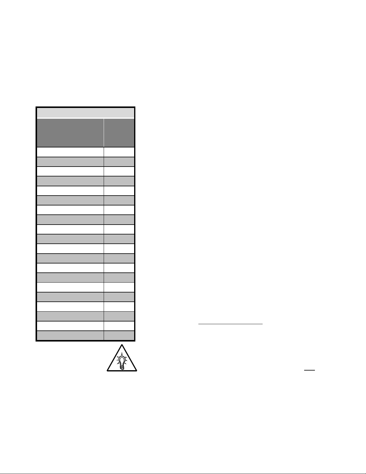
Table 1.2 TE2 Series Range
Model
Number
TE2-18-BP 9 - 18
TE2-28-BP 14 - 28
TE2-39-BP 19 - 39
TE2-48-BP 24 - 48
TE2-62-BP 36 - 62
TE2-78-BP 39 - 78
TE2-92-BP 46 - 92
TE2-112-BP 56 - 112
TE2-150-BP 75 - 150
TE2-160-BP 80 - 160
TE2-210-BP 105 - 210
TE2-275-BP 138 - 275
TE2-361-BP 181 - 361
TE2-450-BP 225 - 450
TE2-550-BP 275 - 550
TE2-600-BP 300 - 600
TE2-862-BP 431 - 862
TE2-900-BP 450 - 900
TE2-1006-BP 503 - 1006
TE2-1250-BP 625 - 1250
Current
Range
Min.- Max.
1.2 Sizes and Ratings
The Toshiba TE2 Series starters are current rated controllers. Max.
Amp ratings are for continuous duty and must not be exceeded. Always
check the motor nameplate FLA and Service Factor to ensure proper
sizing.
Each size has an adjustable current range of 50% to 100% of the Max
Amp rating. Table 1.2 shows the Current Ratings available.
1.2.1 Selecting for Service Factor Utilization
Many NEMA design motors include a design rating referred to
as Service Factor (SF) that may allow continuous operation
above the nameplate current rating. If using this Service
Factor, the TE2 Series starter must be sized for the total amps
used. For proper selection of the TE2 Series starter when
using SF continuously, multiply the nameplate FLA by the
stated Service Factor, or use stated Service Factor Amps
(SFA) if listed on the nameplate. The following excerpt is from
the NEMA MG-1 standards for AC Motors that describes the
issues concerning the use of Service Factor ratings.
"When an induction motor is operated at any service factor
greater than 1.0, it may have efficiency, power factor and
speed different than those at rated load. Locked rotor torque
and current and breakdown torque will remain the same. A
motor operating continuously at any service factor greater than
1.0 will have a reduced life expectancy compared to operating
at its nameplate horsepower."
When using this feature, simply program the TE2 Series
Service Factor (F002) to the nameplate rating. (See section
5.6.1.) All other adjustments to the protection circuits are done
automatically within the TE2 Series.
1.2.2 Selecting for Across the Line Bypass
If you need to be able to start the motor Across-the-Line when
the TE2 Series electronics are out of service, the starter can
also be selected based upon the rating of the Bypass
Contactor. Some users may also elect to size their Bypass
Contactors per NEMA guidelines. When doing this, please
refer to the Product Selection Guide for details and notes, and
see Appendix 4 for special considerations regarding Overload
Protection.
1.2.3 The TE2…-BP Series starters include the ability to connect a
dry contact directly to the Bypass Contactor coil control circuit.
These terminals are covered when shipped and should be used
ONLY when necessary for Emergency Bypass operation and with
an external Overload Relay. See Appendix 4 for additional
information.
No field wiring to these terminals is necessary if this feature is not
used.
TE2 Series Digital Solid State Soft Starter User Manual 4 | Page

Chapter 2 - Installation
2.1 Receiving and Unpacking
Upon receipt of the product, you should immediately do the following:
Carefully unpack the unit from the shipping carton and inspect it for
shipping damage. If damaged, notify the freight carrier and file a
claim within 15 days of receipt.
Verify that the model number on the unit matches your purchase
order.
Confirm that the ratings nameplate on the unit match or are greater
than the motors’ HP and current rating with which it is to be used.
2.2 Choosing a Location
Proper location of the TE2 Series is necessary to achieve specified
performance and normal operational lifetime. The TE2 Series should
always be installed in an area where the following conditions exist:
Ambient operating temperature: 0 to 40°C (32 to 104°F)
Protected from rain, moisture, and direct sun.
Humidity: 5 to 95% non-condensing.
Free from metallic particles, conductive dust, and corrosive gas.
Free from excessive vibration. (below 0.5G)
Open panel units must be mounted in the appropriate type of
enclosure. Enclosure size and type must be suitable to dissipate
heat generated by the soft starter and any other components
mounted inside with it.
Care should always be taken to maximize the available space
inside of the enclosure. See section 2.5.1 or contact factory for
assistance in sizing enclosures.
2.3 Initial Unit Inspection
Make a complete visual check of the unit for damage that may have
occurred during shipping and handling. Do not attempt to continue
installation or start up the unit if it is damaged.
Check for loose mechanical assemblies or broken wires which may
have occurred during transportation or handling. Loose electrical
connections will increase resistance and cause the unit to function
improperly.
Prior to beginning the installation, verify that the motor and TE2
Series unit is rated for the proper amperage and voltage.
TE2 Series Digital Solid State Soft Starter User Manual 5 | Page
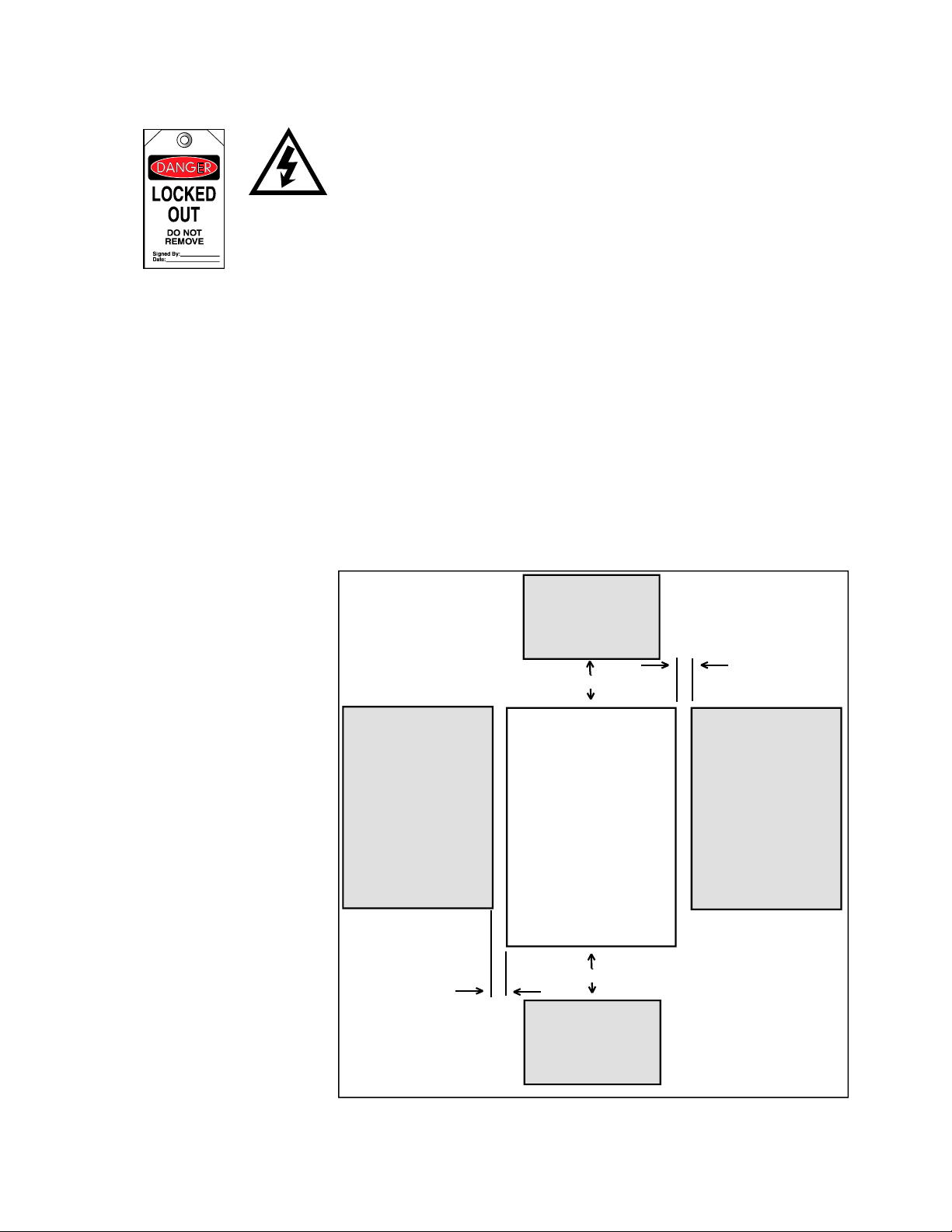
2.4 SERVICE WARNING!
r
Do not service equipment with voltage applied! The unit can be the
source of fatal electrical shocks! To avoid shock hazard,
disconnect main power and control power before working on the
unit. Warning labels must be attached to terminals, enclosure and
control panel to meet local codes. Use Lockout tags such as the
one shown when servicing equipment.
2.5 Mounting and Cleaning
When drilling or punching holes in the enclosure, cover the electrical
assembly to prevent metal filings from becoming lodged in areas which
can cause clearance reduction or actual electrical shorts. After work is
complete, thoroughly clean, vacuum the area, and re-inspect the unit for
foreign material.
2.5.1 Clearances
Make sure there is sufficient clearance all around the unit for cooling,
wiring, and maintenance purposes. To conserve panel space, the TE2
Series - BP models were designed for close clearances of only 1 inch
(25mm) on either side. A minimum clearance of 4 inches (100 mm) on
the top and bottom is necessary to maximize effective airflow and
cooling. Also the unit must be installed with its heat sink ribs oriented
vertically and running parallel to the mounting surface. Keep in mind
that these are minimums. NEC or local codes may require more
clearance, particularly for the power terminals.
4" minimum ( 100 mm )
1" minimum (25 mm )
TE2 Series
Starte
4" minimum ( 100 mm )
1" minimum (25 mm )
Figure 2.5: TE2 minimum mounting clearances
TE2
Series Digital Solid State Soft Starter User Manual 6 | Page
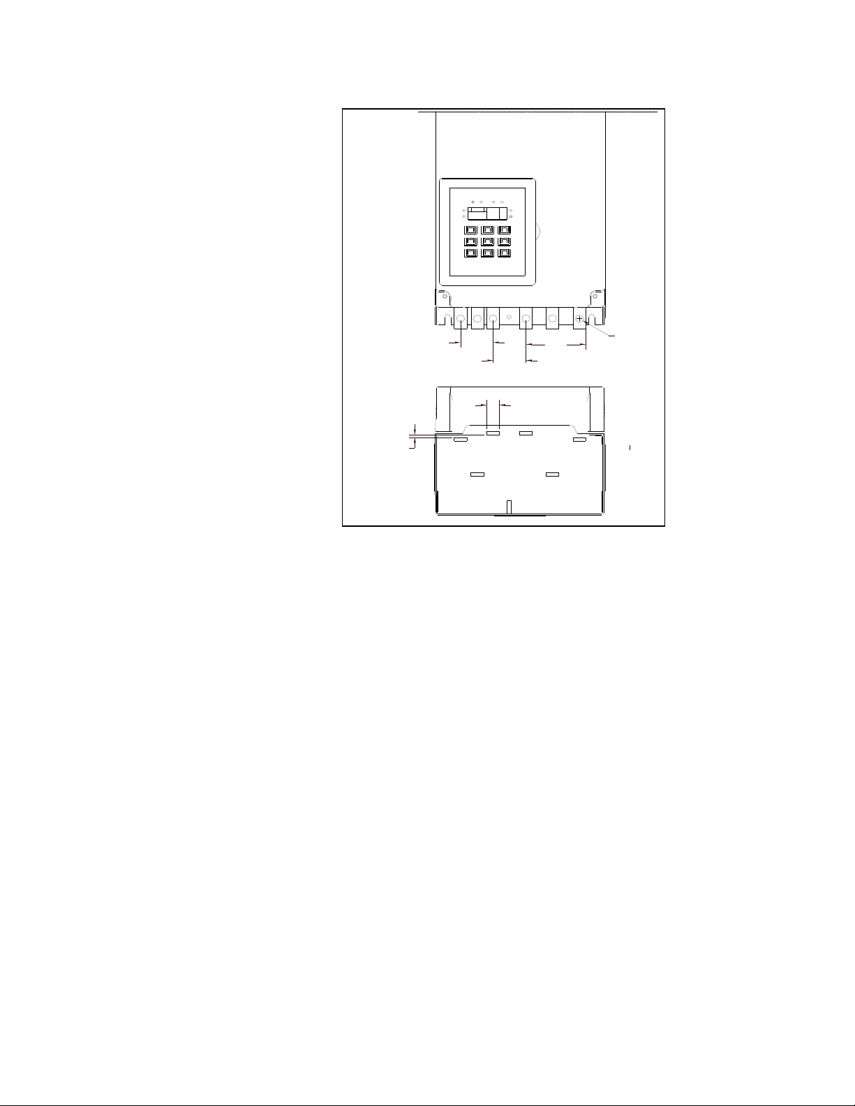
TE2 -18 ~
TE2 -48
(38.07 mm)
Line
Line Load
R/L1 S/L2 T/L3
1.50"
0.45"
(11.42 mm)
Load
V/T2
U/T1 W/ T3/
1.10"
(27.92 mm)
WARNING!
Remove all sources of power before cleaning the unit.
In dirty or contaminated atmospheres, the unit should be cleaned on a
regular basis to ensure proper cooling. Do not use any chemicals to
clean the unit. To remove surface dust, use clean, dry compressed air
only, 80 to 100 psi. A three-inch, high quality, dry paintbrush is helpful to
loosen up the dust prior to using compressed air on the unit. Do not use
wire brushes or other conductive cleaning materials
2.6 Power Terminations
All line and load power terminations are to be made to the tin plated
copper Bus Tabs located on each unit. Bus tabs are pre-drilled to
accept industry standard bolts. Toshiba recommends using crimp-on
ring lugs, although mechanical compression lugs are suitable as well.
The following diagrams show sizes of the bus tab holes and critical
spacing between them for determining the size of lug that can be used.
Note: All wiring must be sized according to local and national code
standards.
TE2-62 ~
TE2 -112
0.19"
(4.82 mm)
Line Load
1.82"
(46.19 mm)
(43.91 mm)
1.73"
0.38"
(9.64 mm)
1.23"
(31.22 mm)
R/L1 T/L3
0.60"
(15.23 mm)
S/L2
Line Load
U/T1 W /T3
V/T2
1.13"
(28.68 mm)
Figure 2.6.1 Critical clearances for bus tab connections
TE2
Series Digital Solid State Soft Starter User Manual 7 | Page
Figure 2.6.2 Critical clearances for bus tab connections
2.6 Power Connections (cont.)
/T3V
TE2 -150 ~
TE2 -160
Line Load
0.38"
1.52"
(38.58 mm)
1.54"
(39.09 mm)
2.81"
(71.32 mm)
(9.64 mm)
0.14"
(3.55 mm)
T/L3
R/L1
S/L2
Line Load
0.60"
(15.23 mm)
U/T1
W
/T2
Figure 2.6.3 Critical clearances for bus tab connections
Note: Consult factory for bus tab critical dimensions for units 210A and above
TE2 Series Digital Solid State Soft Starter User Manual 8 | Page
2.6.1 Power Terminals:
r
r
r
Connection points are bus tabs with pre-drilled holes (see below).
Suggested wire sizes and tightening torques for factory-supplied
connectors using conductors rated for 75C are shown in the chart
below. Always consult local and national codes along with industry
standard practices for proper wires sizes and terminations to
accommodate voltage drop and ambient conditions.
Table 2.6: TE2 Series Wire Ranges and Torque Specifications
Model
Number
TE2-18-BP 9 - 18 10
TE2-28-BP 14 - 28 8
TE2-39-BP 19 - 39 8
TE2-48-BP 24 - 48 6
TE2-62-BP 36 - 62 4
TE2-78-BP 39 - 78 3 35
TE2-92-BP 46 - 92 2 35
TE2-112-BP 56 - 112 1 50
TE2-150-BP 75 - 150 2/0
TE2-160-BP 80 - 160 3/0 95
TE2-210-BP 105 - 210 250
TE2-275-BP 138 - 275 350 kCMIL 185
TE2-361-BP 180 - 361 2 x 300 kCMIL 2 x 150
TE2-450-BP 225 - 450 2 x 300 kCMIL 2 x 150
TE2-550-BP 275 - 550 2 x 400 kCMIL 2 x 240
TE2-600-BP 300 - 600
TE2-862-BP 431 - 862
TE2-900-BP 450 - 900
TE2-1006-BP 503 - 1006
TE2-1250-BP 625 - 1250
Current Range
Min.- Max.
Note: TBD = To Be Determined at a later date
Suggested
Wire Size
AWG
2 x 500 kCMIL TBD
3 x 400 kCMIL TBD
3 x 500 kCMIL TBD
4 x 350 kCMIL TBD
4 x 500 kCMIL TBD
Tightening
Torque
in.-lbs.
35
45
80
200
Screw / Bolt
Size
1 x M5
(included)
1 x M8
(included)
1 x M8
(included)
1 x 0.38" hole
(M10)
for User
supplied
lugs
TBD TBD 2 x 300
TBD TBD 3 x 240
TBD TBD 3 x 300
TBD TBD 4 x 185
TBD TBD 4 x 300
Tightening
Torque
Nm
4
5
9
15
Suggested
Wire Size
ISOmm2
6
10
10
16
25
70
150
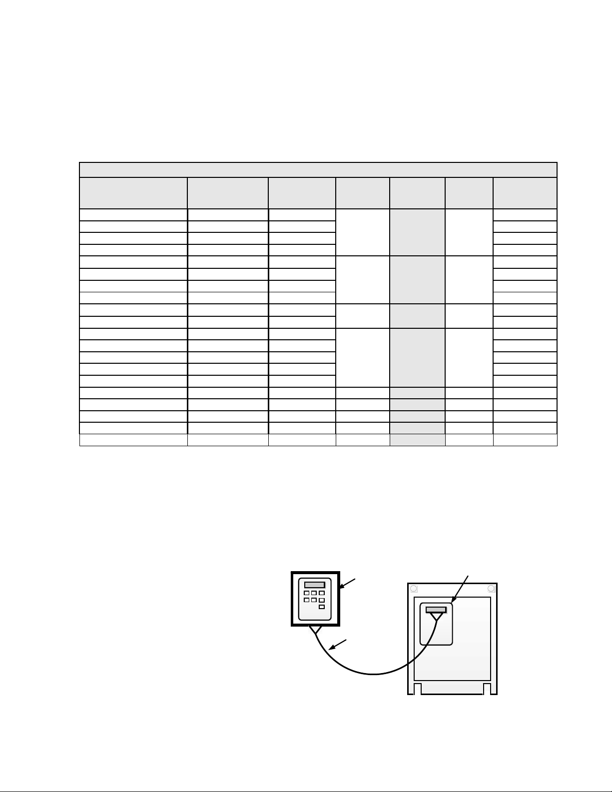
2.7 Remote Keypad Mounting
The keypad / operator interface unit can be remotely mounted up to 10ft
(3 meters) away from the starter, i.e. on the enclosure door. A remote
mounting kit is necessary, which consists of an adaptor plate, a
doorframe for NEMA 1 or NEMA 12 enclosures and a pre-assembled
ribbon cable available in 1-meter length increments. Detailed assembly
instructions and an enclosure cutout template are included with the kit.
See Product Selection Guide for part numbers of the available kits.
NEMA12
Door Frame
Figure 2.7
Remote Keypad Mounting Kit
Components
Adaptor Plate
Ribbon Cable,
3 Me ter s
1, 2, o
(3. 28, 6.56, o
9.84 feet.)
TE 2 Starte
TE2 Series Digital Solid State Soft Starter User Manual 9 | Page
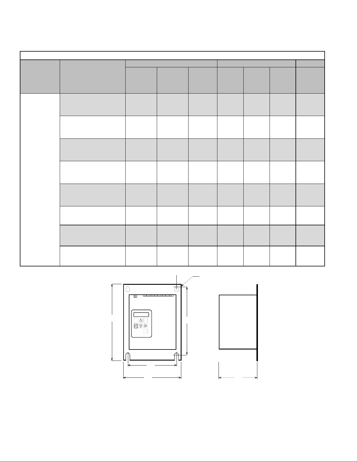
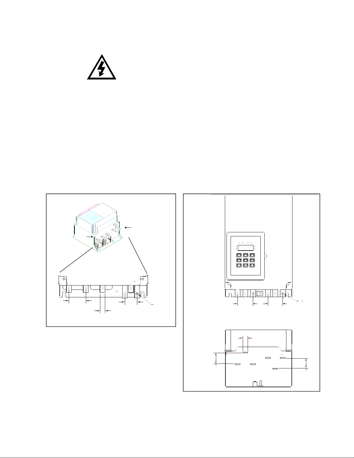
2.8 Dimensions (consult price catalog for enclosed units)
Table 2.8: TE2 Dimensions and Weights
Overall Mounting
Enclosure Model Number
TE2-18-BP through
TE2-48-BP
TE2-62-BP through
TE2-112-BP
TE2-150-BP and
TE2-160-BP
Panel (open)
with integral
TE2 -210-BP and
TE2-275-BP
bypass
contactor
TE2-361-BP and
TE2-450-BP
TE2-550-BP through
TE2 -600-BP
TE2-862-BP through
TE2-900-BP
A
Inches
(mm)
8.85
(230)
14.00
(355.6)
19.00
(487.9)
28.10
(723.9)
29.30
(744)
29.50
(786.9)
44.25
(1124)
B
Inches
(mm)
8.00
(203)
8.00
(203)
8.00
(203)
12.5
(317.5)
12.5
(317.5)
12.5
(317.5)
25.5
(647.7)
C
Inches
(mm)
6.65
(169.7)
6.65
(169.7)
6.65
(169.7)
9.1
(229.4)
9.1
(229.4)
9.1
(229.9)
11.86
(301.3)
D
Inches
(mm)
8.06
(204.7)
13.25
(336.6)
18.25
(463.6)
27.38
(695.5)
27.38
(695.5)
27.38
(695.5)
43.00
(1092.2)
E
Inches
(mm)
7.00
(177.8)
6.75
(171.5)
6.75
(171.5)
10.75
(273.1)
10.75
(273.1)
10.75
(273.1)
23.00
(584.2)
F
Inches
(mm)
0.22
(5.6)
0.28
(7.1)
0.28
(7.1)
0.40
(10.2)
0.40
(10.2)
0.40
(10.2)
0.40
(10.2)
Weight
lbs
(kg)
13
(5.9)
23
(10.4)
35
(15.9)
90
(40.9)
105
(47.7)
120
(55)
Contact
Factory
TE2-1006-BP through
TE2 -1250-BP
50.77
(1182.6)
25.5
(716.3)
13.28
(332.7)
Fdia.
42.75
(1095.9)
23.25
(590.5)
0.40
(10.2)
Contact
Factory
Figure 2.8: TE2 Dimensions
A
~ ~
D
~
E
B
C
TE2 Series Digital Solid State Soft Starter User Manual 10 | Page
Chapter 3 - Motor Overload Protection
3.1 Solid State Overload Protection
MOTOR FLA (F001)
must be programmed
for unit to operate!
Examples:
H100
100% Thermal
Capacity remaining
at rest
H057
57% Thermal Capacity
remaining after starter
(43% used)
The TE2 Series Starter provides true U.L. listed I
Protection as a built-in function of the main digital processor for
maximum motor protection. It mimics the tripping action of a bi-metallic
overload relay, with the accuracy and repeatability of a digital control
system. It is adjustable over a wide range and is easily be programmed
to different trip curves.
3.1.1 Thermal Memory
The TE2 Series microprocessor uses a sophisticated “Thermal
Register” in the digital memory to keep track of motor heating and
cooling over time regardless of the starter’s power status. By using nonvolatile memory, the TE2 Series does not “forget” that the motor has
been running even if power to the starter is turned off and turned back
on. Continuous overload protection is provided based on the true
thermal condition of the motor.
3.1.2 Thermal Capacity
The Thermal Register is displayed as a percentage. This percentage is
the motor’s remaining thermal capacity. The percentage value begins at
100; showing that the motor is cool (has 100% of its capacity available).
As the motor heats up or moves toward an overload condition, the
percentage begins to drop. The Thermal Capacity is derived from the
programmed motor nameplate Full Load Amps (FLA) in Function F001,
the Service Factor rating in Function F002, and the Overload Trip Class
in Functions F003 and F004. Setting these functions to the proper
values provides maximum protection and eliminates nuisance tripping.
The Remaining Thermal Capacity is viewed by using the UP or DOWN
arrow keys when in the Status Display mode. From the default Phase A
Current screen (dot on right side), press the UP arrow key 4 times to
display [H100] meaning there is 100% of the Thermal Capacity (H =
Heat capacity) remaining in the motor. After starting or running, the
motor will use this capacity and the display will show a lower number.
For example, after a cold start, the display may read [H065] which
indicates that the motor has 65% of its thermal capacity remaining (35%
used). The Status Display screens cycle back to the beginning, so the
Down arrow keys can access this display as well.
3.1.2.a Motor Full Load (FLA) Setting
Use Function F001 to enter motor FLA as indicated on the motor
nameplate. (Do not calculate for service factor, this is programmed
separately in F002).
Note:
All TE2 Series starters are shipped from the factory with F001 set
to a default value of 0000. If F001 is left at the factory default, the
unit will not operate. If the user attempts to start the TE2 Series
without entering the motor nameplate FLA, the starter will Fault and
the display will read “nFLA” (no Full Load Amps).
2
t Thermal Overload
TE2
Series Digital Solid State Soft Starter User Manual 11 | Page
3.1.3 Disabling the Overload Protection
The Overload Protection feature can be disabled if necessary. When
using external devices such as Motor Protection Relays or when the
TE2 Series is wired downstream from an existing starter, this feature
can be disabled to prevent conflicts with external Overload Protection
devices. When the TE2 Series is controlling multiple motors, the built-in
Overload Protection must be disabled and individual thermal overload
relays must be installed on the motor leads going to each motor (see
Appendix 4 for additional details). To disable the Overload Protection
function, use F005.
WARNING!
Do NOT disable Overload Protection unless another Thermal
Overload Protection device exists in the circuit for all three
phases. Running a motor without Overload Protection presents serious
risk of motor damage or fire.
3.1.3.a Manual Reset
The factory default setting is Manual Reset. This means that when
the Overload Trip is activated, the starter cannot be restarted
without pressing the Reset key. The Overload Trip will not reset
until the motor cools down (see 3.1.3.d). The Manual Reset function
is also “trip free”. Holding in the Reset key will not prevent the
Overload Trip from activating and protecting the motor.
Note:
When the Overload Trip activates, the Overload LED will be on
solid. When the motor cools down, the LED will begin to flash,
indicating that the Overload Trip can be reset.
3.1.3.b Automatic Reset
If Automatic Reset is necessary, change from Manual Reset to
Automatic Reset by using Function F005. (See Section 5 for
details). In this mode, a 3-wire control circuit will be capable of
restart when the TE2 Series has reset itself after the cool down
period.
WARNING!
Two-wire control systems may restart without warning when Auto
Reset of the Overload Protection is selected. Extreme caution
should be exercised. To prevent automatic restarting with 2-wire
control systems, use external interlocking to provide sufficient
warning and safety to operators. A Warning Label similar to that
shown below (and the one provided in the packet with this manual)
must be located where visible (on the starter enclosure and/or the
driven equipment) as required by local code.
WARNING: M OT OR CONNECT ED T O T HIS EQUIPM ENT
MAY ST ART AUT OMAT ICALLY WIT HOUT WARNING
TE2 Series Digital Solid State Soft Starter User Manual 12 | Page

3.1.3.c Overload Protection During Bypass
When an integral Bypass Contactor is used to shunt power around
the SCRs in the TE2 Series (as in the TE2…-BP version), overload
protection is maintained as long as the TE2 Series is directly
controlling the contactor. No additional Overload Relay is
necessary for normal operation.
When the Bypass Contactor on a TE2…-BP Series has been
selected to be used for Across-the-Line restart (reference section
1.2.3), supplemental overload protection is necessary. For this
application, refer to the External Overload Relay Applications
supplement and wiring diagram in Appendix 4.
3.1.3.d Dynamic Reset Capacity
The TE2 Series includes the ability to dynamically track the
Thermal Capacity needed for a successful restart after an overload
trip. It averages the Thermal Capacity consumed in the previous
three successful starts, and calculates a Thermal Capacity to Start
(viewed in Function F059). After tripping on Overload, the Thermal
Register must have regained the amount recorded in F059 before a
Reset will be allowed. If the display reads [Inh] when attempting to
reset an overload trip, it is indicating that the starter is Inhibited from
being reset.
Refer to details of Function F071 for information on emergency
override of lockouts such as this.
3.2 NEMA Class Trip Curves
NEMA Class trip curves are based on a common tripping point of 600%
of motor Full Load Amps (FLA). Curves vary by the amount of time
before the unit trips. As an example, a Class 20 curve will trip in 20
seconds at 600% of FLA. The factory default setting of Class 10 will trip
in 10 seconds at 600% of FLA.
3.2.1 Dual Overload Trip Curves
The TE2 Series Soft Starter provides two separate Overload Trip
Protection Curves, one for starting and one for running conditions. The
starter’s At-Speed detection circuit determines when the motor has
reached full speed. When the At-Speed condition is reached, the
overload trip curve will shift from the Start to the Run level, as
programmed in Functions F003 and F004. See Section 5.6.1 for
programming details.
3.2.2 Starting Overload Trip Curve
During the start mode, Overload Trip Curves are selectable from NEMA
Class 5 through Class 30 only. The default setting of Class 10 allows
protection for the overload capacity of the soft starter as well as the
motor. Use a higher Trip Class only if nuisance tripping occurs with the
default setting.
TE2 Series Digital Solid State Soft Starter User Manual 13 | Page
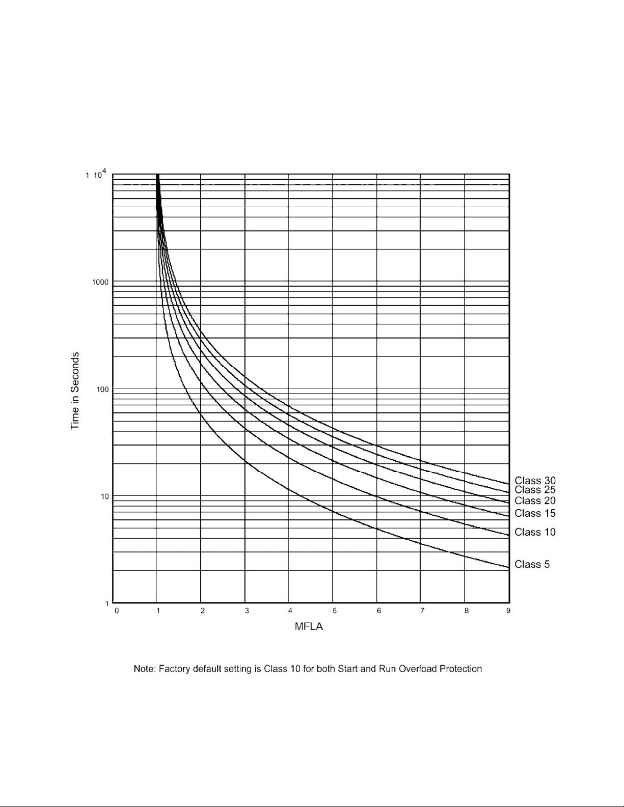
3.2.3 Running Overload Curve
During the Run mode, Overload Trip curves are selectable from NEMA
Class 5, 10, 15, 20, 25, and 30. Program the appropriate curve
according to the characteristics of your motor and load.
3.2.4 Overload Trip Curve Chart
TE2
Series Digital Solid State Soft Starter User Manual 14 | Page
Figure 3.2.4: TE2 Series Overload Trip Curves
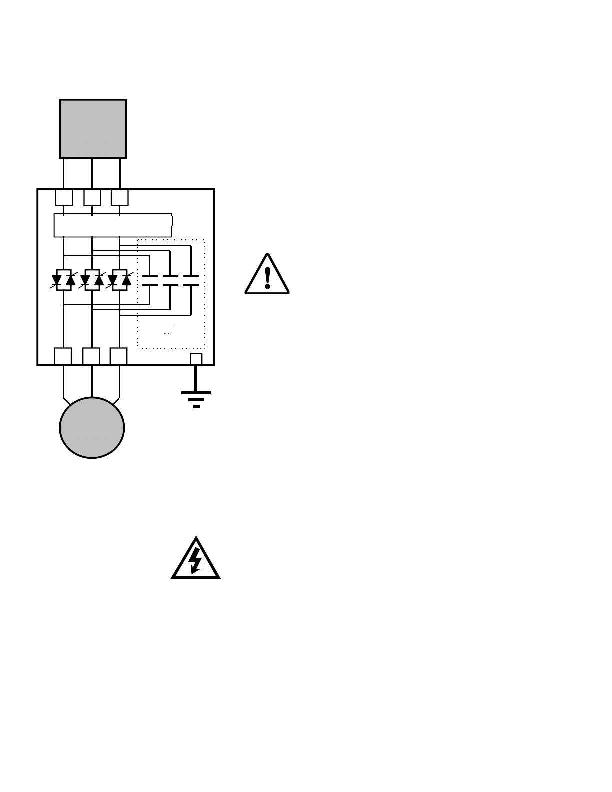
Chapter 4 - Connections
r
r
/
V /
Disconnect
o
Circuit
Breaker
R /
L1
U /
T1
T2
S /
L2
T
TE2 Starte
L3
Solid State
Overload
W /
T3
.
.
Integral
Bypass
Contactor*
.
G
MTR
4.1.2 Power Factor Correction Capacitors
Power factor correction capacitors can be connected to motors
TE2 Power Connections
Figure 4.1:
4.1 Power Connections
Refer to national and local code for wire sizing and length, connect
power conductors to the unit input terminals marked L1, L2, L3 (R, S, T
for IEC users). Use appropriate compression or mechanical lugs for
termination to these bus tabs. Avoid routing power wires over the
control board or display. Connect the motor leads to the unit terminals
marked T1, T2, T3 (U, V, W for IEC users). If control power is present,
but line power is disconnected from L1, L2, L3, the display will show
[n3PH] indicating “no 3 Phase”.
Caution!
Never interchange input and output connections to
the unit. This could cause excessive voltage in the
control logic circuit and may damage the unit.
4.1.1 Bypass Contactor
Bypass Contactors are integral (built-in) on all TE2 sizes. See sections
1.2.3, 3.1.3.c, and Appendix 4 for more details on contactor control and
overload protection details.
controlled by TE2 Series starters; however they must be off-line during
ramping. Connect PFC capacitors to the Line side of the starter with a
separate capacitor control contactor.
WARNING!
Never connect power factor correction capacitors on the load side
of the unit. The SCRs will be seriously damaged if capacitors are
located on the load side.
4.1.3 Grounding
Connect the ground cable to the ground terminal as labeled on the unit.
Refer to the National Electrical Code or your local Code for the proper
ground wire size, and be sure that the ground connector is connected to
earth ground.
TE2
Series Digital Solid State Soft Starter User Manual 15 | Page
4.1.4 Testing
The TE2 Series can be tested with a load smaller than the motor it was
originally selected to control, however additional steps must be taken to
avoid tripping on Phase Current Loss. See section 5.6.8.a under “Phase
Loss Protection” for additional details on performing this task.
Notes:
The unit cannot be tested without a motor or other test load
connected to the load side of the unit. It may be necessary to use a
load bank to test the unit without a motor.
Line voltage will appear across the output terminals if there is no
motor or load connected to the unit.
4.1.5 Lightning Protection
As with all electronic power controllers, protection from damage by
lightning surges is recommended in areas where lightning is a
significant problem. Stationary SPDs (Surge Protection Device) should
be considered and utilized on the input power source. The best method
of protection is to have an Isolation Contactor in front of the starter that
is open when the soft starter is not in use. Enclosed versions may be
provided with a surge protection device.
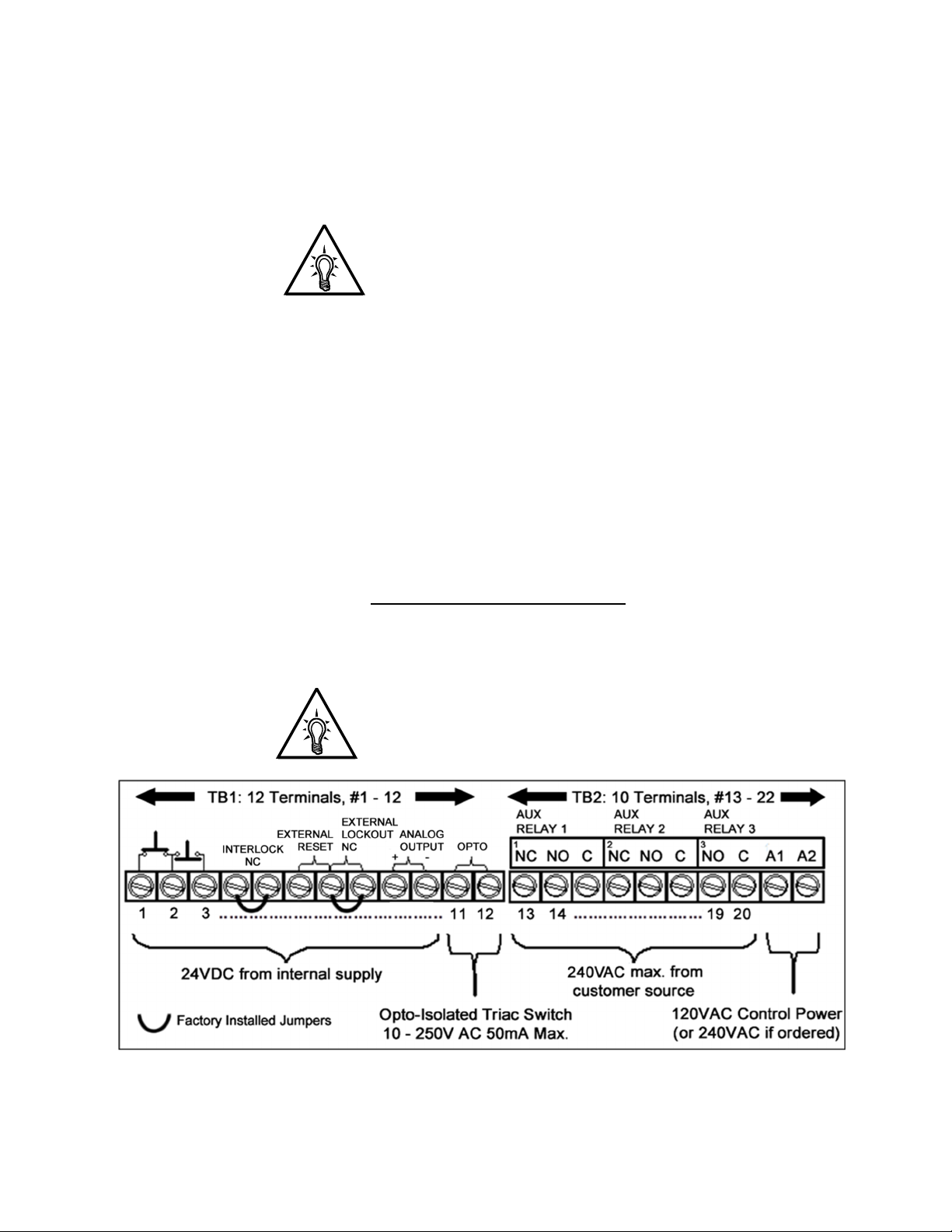
4.2 Control Connections
Control connections on the TE2 Series starter are divided into 2 groups.
With the unit oriented vertically, TB1 is a 12-point DC terminal block (on
the left), and TB2 is a 10-point AC terminal block (on the right side).
These are removable terminal blocks for ease of connection and
servicing, and are provided with different spacing (pitch) between the
header pins, so they are not interchangeable. Following are descriptions
of control connection points.
Note:
Terminal numbers are shown on the side of the first and last
terminal of each block. An additional 3 point terminal on the far left
side is for serial communication connections (see section 5.6.10).
TE2
Series Digital Solid State Soft Starter User Manual 16 | Page
Figure 4.2: Control Terminal Blocks
1
NC NO. C
2
NC NO. C3NO. C
Control Power Supply Connection
Figure 4.2.1
TB-2
4.2.1 AC Control Power Supply Connection
120VAC
Supply
1
A1 A2
Separate AC Control Power supply is required to power the electronics
of the TE2 Series starter. The standard is 120VAC, but 240VAC
(optional) can be ordered if necessary for your line power supply
configuration. The control voltage must be connected to terminals
marked A1 and A2 of TB-2 as shown in figure 4.2.1 (these are also
Terminal No.’s 21 and 22). This control voltage must be customer
supplied, unless an optional control power transformer (see table below)
has been supplied with the unit.
Table 3: TE2 Series AC Control Power VA Requirements
TE2…-BP
Model
TE2-18 to 48 48 (inc. in PCB) 95 9 100
TE2-62 to 112 48 (inc. in PCB) 220 17 250
TE2-150 to 160 48 72 298 12.3 500
TE2-210 to 276 48 100 380 11.6 500
TE2-360 to 450 48 150 571 14 750
TE2-550 48 200 1000 29 1000
PC
Boards
Fans
-BP: Bypass
Contactor
Inrush
-BP: Bypass
Contactor
Sealed
Recommended
minimum
CPT
Rating
4.2.1.a Control Power Requirements
When sizing a control power transformer for the TE2…-BP Series
starter use the above chart for minimum sizes or supply capacity.
Any additional control devices powered by the same CPT must be
added to the above values to ensure proper operation of the Bypass
Contactor.
4.2.1.b Control Fusing
The output relay contacts (TB2) must be protected from currents in
excess of 5A by either using fuses or other suitable current
protection devices.
A dedicated fault output for use in PLC or interposing relay control
is available on TB1. This opto-isolated Triac switch is rated for
50mA max., 10-250V AC. Any circuit connected to it must be fused
accordingly.
TE2 Series Digital Solid State Soft Starter User Manual 17 | Page
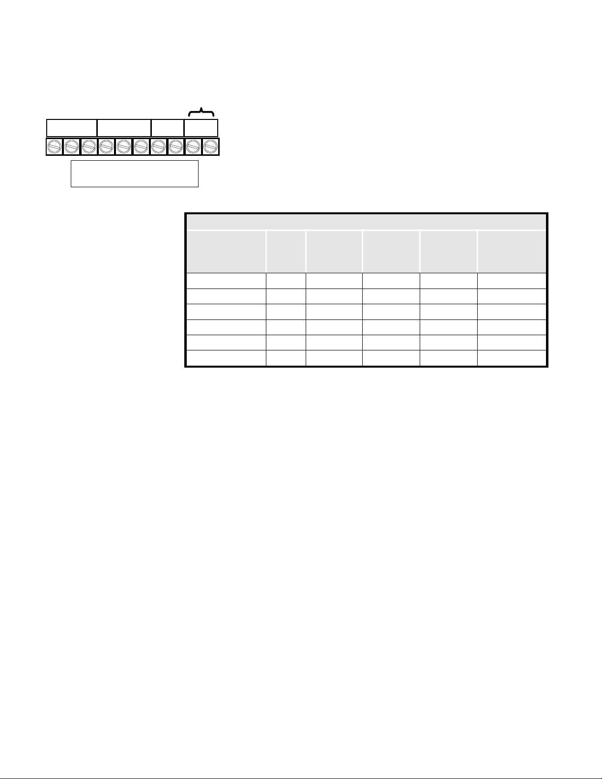
4.2.2 Three-Wire Control Connection
For standard 3-wire control, connect dry (voltage free) contacts for the
Stop / Start buttons as shown on the diagram directly above the terminal
strip. Connect the N.O. contact of the Start button to Terminal 1 (far left
terminal), the common point between the Stop and Start to Terminal 2
nd
(2
from left) and the N.C. from the Stop button to Terminal 3 (3rd from
left).
4.2.2.a Seal In Contact
The TE2 Series uses an internally pre-wired “seal-in” contact
around the Start button (Terminals 1 and 2). No external relay or
auxiliary output connection is necessary.
4.2.3 Two Wire Control: Relay / PLC Connection
An alternate connection for automated or unattended operation replaces
the start/stop push buttons by connecting a dry (voltage free)
maintained contact closure between terminals 1 and 3 as shown in
Figure 4.2.3. When this contact is closed, the TE2 Series starter will
start and run. When it is opened, it is the same as a Stop command.
4.2.3.a Automatic Functions and 2-Wire Control
When using the Auto Reset functions (F052 - F053), special
consideration must be given to using 2-wire control. Refer to section
5.6.8 for details on using Auto-Reset functions.
Note:
When a maintained contact is used for start/stop, it is advisable to
set the overload relay to the manual reset position. This will prevent
the motor from restarting if the thermal overload trips and then cools
down.
CAUTION!
Control Terminals 1-10 of TB1 are configured using solid state
devices powered internally with a 24VDC power supply. To prevent
damage to the TE2 Series control board, use dry (unpowered)
contact closures only when connecting to these terminals.
If existing 120VAC or other powered control circuit must be
interfaced, use isolating relays.
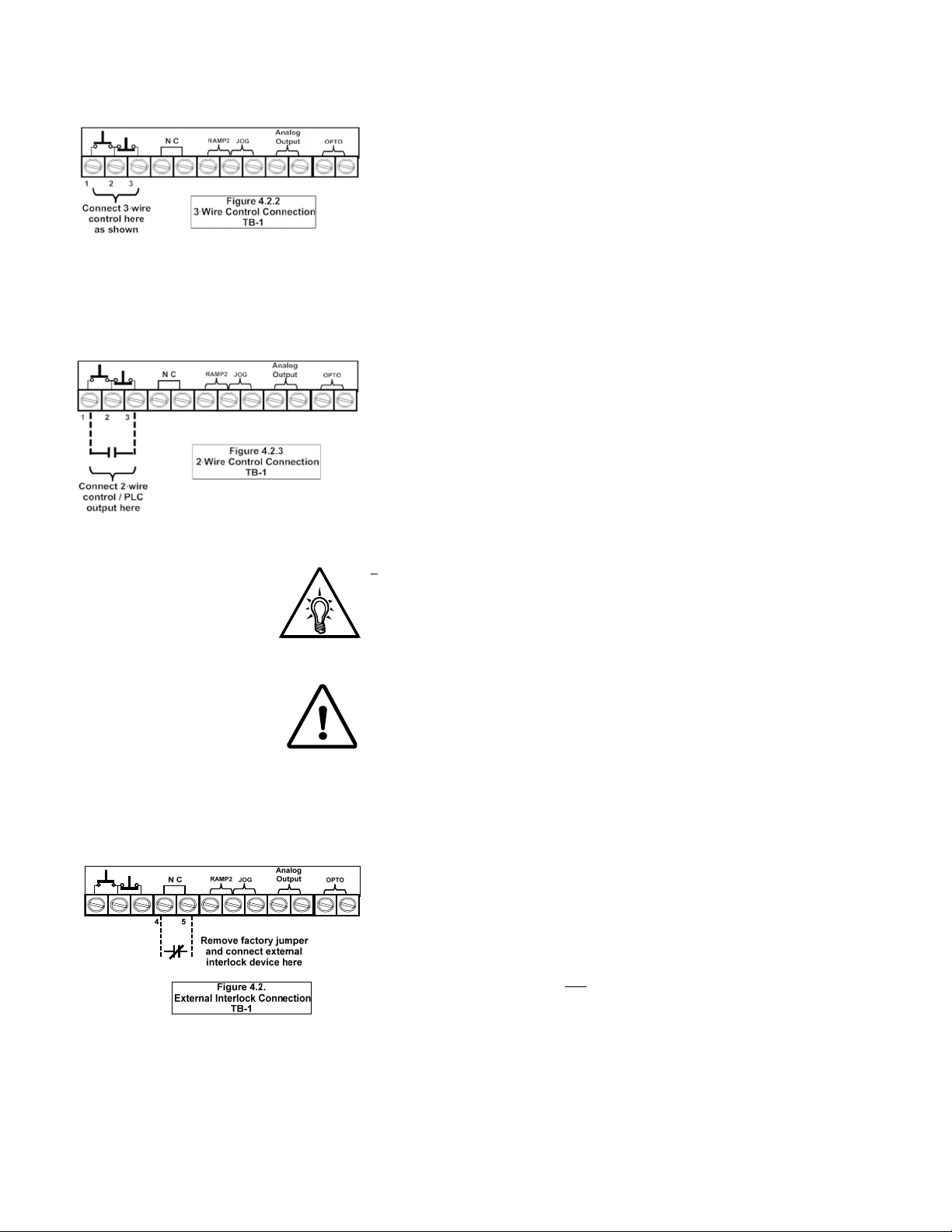
4.2.4 Interlock Connection
TB1 provides a connection point for an external dry (voltage free) N.C.
(Normally Closed) interlock device between terminals 4 and 5.
Examples where this interlock connection would be used include low oil,
high temperature, or excess vibration dropout from user supplied
devices. A factory-installed jumper is provided which allows the TE2
Series unit to operate if external interlocks are not used. If this jumper is
removed and an interlock is not used, the TE2 Series unit will not
function.
TE2
Series Digital Solid State Soft Starter User Manual 18 | Page
Note: Ramp 2 terminals are defaulted as
“External Reset”, see parameter F113 for
other options.
Note: Jog terminals are defaulted as
“External Lockout, Normally Closed”, see
parameter F113 for other options.
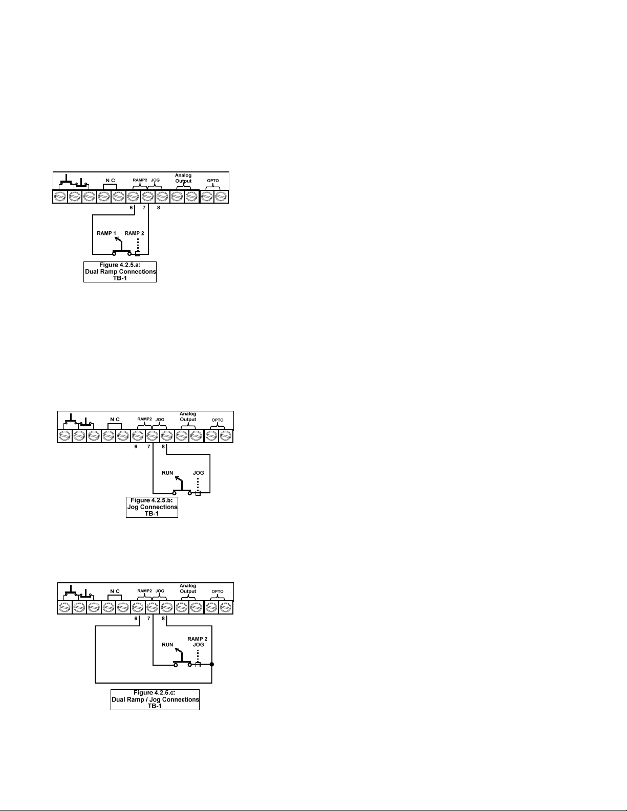
4.2.5 Enabling the Dual Ramp and Jog Features
TB1 includes provisions for enabling the Dual Ramp and Jog functions
by using external contact closures. Both features use a common
+24VDC from Terminal 7. However, they can be used independently of
each other or together. See sections 5.6.2 and 5.6.3 for full function
descriptions and setup.
4.2.5.a Dual Ramp Command
Closing a dry (voltage free) contact between TB1, terminals 6 and 7
will enable Ramp 2, and the TE2 Series starter will respond to the
settings for Ramp 2 in F015 - F018. If no contact closure is present,
the TE2 Series starter defaults to the Ramp 1 parameters (F011 -
F014). See Section 5.6.2.a for setup of the Dual Ramp Feature.
The Dual Ramp feature is useful in instances where the load
changes significantly. Example: a loaded or unloaded conveyor belt.
The characteristics for starting an unloaded conveyor can be
programmed for Ramp 1. The characteristics for starting a loaded
conveyor can be programmed for Ramp 2. Ramp 2 can also be
programmed for Full Voltage / Across-the-Line starting by setting
the ramp time to 0 and Current to 600%.
Dual Ramp is also useful in 2-speed motor applications. Simply use
an auxiliary contact from one of the speed contactors to select
Ramp 2 so that separate ramp profiles can be used.
Dual Ramp input can also be configured as a “Remote reset”
(See parameter F113 and associated table)
4.2.5.b Jog / Remote Command
Connecting a dry (voltage free) contact between TB1, Terminals 7
and 8 will enable the Jog feature. A Start command (Run Command
or Start button) is required to activate the Jog feature. See Section
5.6.3 for setup of the Jog Function.
The Jog feature can be used for tasks such as lining up machines
for blade or bit changes, or inching belts along to check tracking.
This input is also used to change the function of the Serial
Communications port control through F068. For additional
information, see instructions of that function in section 5.6.11.
Jog input can be also configured as:
“Remote” (via comm. link) / “Local” (T-strip), Start stop control.
“External Lockout” (N.O.)
“External Lockout” (N.C.)
(See parameter F113 and associated table)
4.2.5.c Using Both Commands
It may be useful to initialize the Ramp 2 and Jog command
simultaneously when jogging. If this is the case, terminals 6 and 8
can be jumped together and controlled with one contact closure to
Terminal 7 (the common 24VDC).
TE2 Series Digital Solid State Soft Starter User Manual 19 | Page
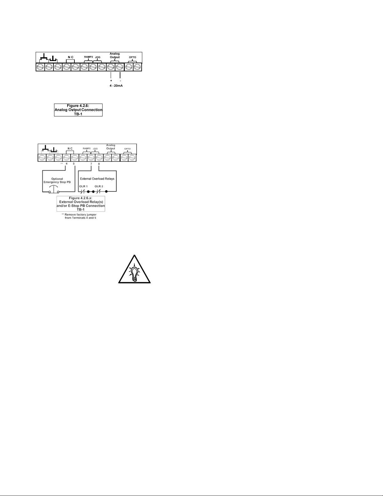
4.2.6 Analog Output (4-20mA)
The TE2 Series starter provides a 4 to 20 milliamp output signal that
can be set to monitor different parameter values using F108 and scaled
with parameter F109 and F110. See section 5.5.16.
4.2.6.a External Overload Relay Connection
If an external Overload Relay (OLR) is used (see Section 3.1.3.c and
Appendix 4), connect the N.C. aux. contact of the OLR across the
Jog input (TB1 terminals 7&8), and re-program the Jog input for
“External Lockout N/C”, by changing F113 per table in sect 5.6.17.
When the external OLR trips, the contact will open. This indicates an
immediate Overload to the starter, which trips and displays [LcA,
Lcc, or Lcd] depending on operation mode when the overload trips.
If multiple OLRs are used, i.e. multiple motors controlled by the same
TE2 Series starter, simply wire the Aux Contacts in series as shown
in Figure 4.2.6.a. See Appendix 4 for additional information.
Note:
This feature is especially useful when using Deceleration Control
because it will immediately shut off power to the motor even if
Deceleration is active. If used this way, the trip indication will be
[LcA, Lcc, or Lcd] depending on the operation mode when the trip
is issued.
TE2
Series Digital Solid State Soft Starter User Manual 20 | Page
Internal Connections
K3
1
NC NO. C
13 14 15 16 17 18 19 20
AUX.
RELA Y # 1
2
NC NO. C3NO. C
AUX.
RELA Y #2
Figure 4.2.8
Auxiliary Relay Conne ctions
TB-2
K5K4
AUX.
RELA Y #3
1
A1 A2
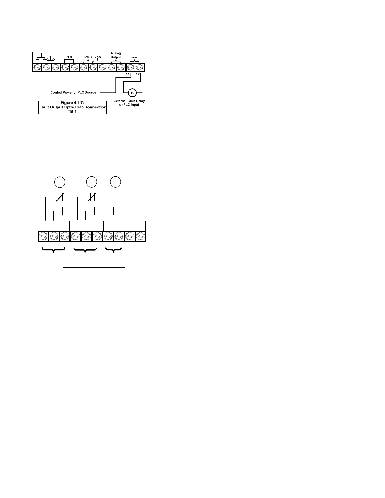
4.2.7 Fault Signal
An optically isolated Triac output is dedicated as a fault indicator on
TB1, terminals 11 and 12, labeled “Opto”. The output Triac switch is
rated for 10 - 250VAC, 50 mA (maximum). If the three programmable
Output Auxiliary Relays are being used for other functions, this output
can easily be hooked up to a PLC or small external relay to provide a
Fault signal. This Fault Output operation is permanently fixed at “Any
Trip”, duplicating the relay setting 22 as shown in Table 5.6.9.
This output is permanently set to this function and is not
programmable.
4.2.8 Output (Auxiliary) Relay Contacts
Three programmable auxiliary relays are on TB2. The TE2 Series
starter comes with three programmable dry relay output contacts.
Outputs 1 and 2 are Form C (SPDT), with a Common, N.O. and N.C.
Output 3 is a Form A, (SPST), N.O. contact. It is not necessary to use
the programmable output auxiliary relays in the Start / Stop circuit. An
internal seal-in relay is provided elsewhere (see 4.2.2.a). Toshiba
recommends fusing all outputs with external fuses.
The relays are rated for 240VAC, 5 A and 1200 VA.
Factory default settings for these relays are as follows:
AUX 1 - Run / Stop (see F060).This contact changes state upon a
Start command, returns to normal on Stop (or Begin Decel if active).
AUX 2 - At-Speed / Stop (see F061).This contact changes state
upon the TE2 Series detecting At-Speed, and returns to normal on
Stop. At-Speed is determined by the TE2 Series detecting the
current dropping after reaching End-of-Ramp, or a maximum of 30
seconds after Start.
AUX 3 - Any Trip (see F062) This contact closes when any trip
condition 5 - 21 (as defined in Table 5.6.9) occurs.
All relays can be reprogrammed for a wide variety of functions.
See Section 5.6.9 for additional relay programming details.
TE2 Series Digital Solid State Soft Starter User Manual 21 | Page
 Loading...