


TCB-PCMO4E
1
English
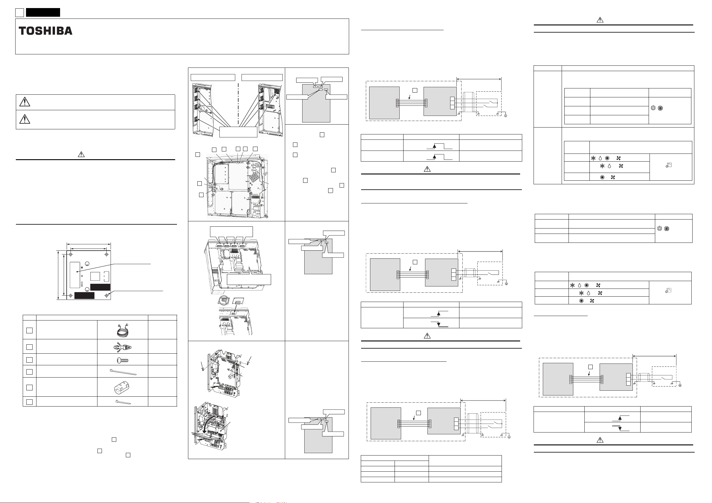
INSTALLATION MANUAL Model:TCB-PCMO4E
External master ON/OFF control board
Precautions for Safety
• Read these “Precautions for Safety” carefully before installation work.
• The precautions described below include important items regarding safety. Observe them without
fail.Understand the following details (indications a nd symbols) before reading the body text, and follow
the instructions.
The meanings of indications
Text set off in this manner indicates that failure to adhere to
WARNING
CAUTION
• After completion of installation, perform trial operation to check for any problems. Explain method of
use and maintenance to the customer by following the descriptions in the manual. Ask customer to
keep this Manual at accessible place for future reference.
• Only a qualified installer or qualified service person is allowed to do installation work.
If installation is carried out by an unqualified individual, fire or electric shock may result.
• Perform installation work reliably according to this installation manual.
Incomplete installation may cause electric shock, fire or abnormal operation.
• Electrical work must be performed by a qualified installer or qualified service person in
accordance with this installation manual. The work must satisfy all local, national and
international regulations.
Inappropriate work may result in electric shock or fire.
• Connect the specified wires firmly and clamp them securely so that external force applied to
the wires does not affect the connector pins.
Improper wire connection or clamping may result in fire or malfunction.
• Do not disassemble, modify, repair or move the product yourself.
Doing so may cause fire, electric shock, injury or water leaks.
• Ask a qualified installer or qualified service person to do any repairs or to move the product.
1 External View
60
2 Accessories
No. Part Name Q'ty
Connection cable 1
1
Support to fix the board 4
2
Earth screw 2
3
Binding band A 4
4
Clamp filter 2
5
Binding band B 2
6
3 Installation
1. Before starting installation work, be sure to turn the power supply OFF.
2. Install the "optional PCB" at the position on the electrical components box shown in the
figure below.
3. Install the "optional PCB" at the specified location inside the electrical components box
using the fixing support.
4. There are four mounting holes for the fixing support ( ) at specified locations inside the
electrical components box.
5. Connect the connector (PJ17) on the "optional PCB" to the connector (CN513) on the
"interface PCB" using the connection cable ( ) . (See figure on right.)
6. The cable (provided) is long. Tie it using the binding band A ( ).
the directions in the warning could result in serious bodily
harm or loss of life if the product is handled improperly.
Text set off in this manner indicates that failure to adhere to
the directions in the caution could result in serious bodily
injury or damage to property if the product is handled
improperly.
WARNING
55.5
45.5
TOSHIBA
NCC-1214
TCB-PCMO1
TCB-PCMO1E
10
COOLHEAT
50
COM
1
4
D2
TB1
8
PJ17
ICI
5
1
Terminal block (M3)
4
1
4-4 mm dia. mounting holes
2
4
[PCB Installation Position]
SMMS-i
MMY-MAP080 to 120
Optional PCB
(max. number installed: 4 pcs)
-b
4
1
-a
4
Optional
PCB
6
5
SMMS, SHRM
Optional PCB
(outdoor unit control PCB)
Incorrect Correct
(max. number installed: 4 pcs)
MiNi-SMMS
Screw
(max. number installed: 2 pcs)
MMY-MAP140, 160
5
Interface PCB
Optional P.C. board
• Optional PCB (both side)
-b
4
6
Screw
Hook part
Interface P.C.
board
Input
wiring
SMMS-i
Connector Positions
CN508 (red)
CN509 (black)
interface PCB
CN510 (white)
CN512 (blue)
Outdoor unit
1. Tie the input wiring using the
binding band A ( ) at the
position in the figure on the left.
( -a):Tie the input wiring
4
together with other leads.
( -b):Tie the input wiring after
4
passing the upper fixation hole
on of the binding band.
2. Attach the clamp filter ( ) to
the input wiring and connection
cable ( ) as shown in the
figure. Use binding band B ( )
to fix the clamp filter ( ) to the
wirings.
* When more than one optional
PC boards are installed, band
all the connection cables and
attach one clamp filter.
SMMS, SHRM
Connector Positions
CN508 (red)
CN509 (black)
Install this optional P.C. board to the
back side of the Interface P.C. board
on outdoor unit.
1. If the screw of the position
shown in the figure is removed
and an upper right hook is
slipped, an interface board will
open.
2. Place this P.C. board by using
the support of the electric
component box. There are four
installation holes to place the
support of the electric
component box.
MiNi-SMMS
Connector Positions
CN508 (red)
CN509 (black)
1
Outdoor unit
interface PCB
Outdoor unit
interface PCB
4
5
5
CN510 (white)
CN512 (blue)
CN510 (white)
CN512 (blue)
4 Details of Operation, Wiring Diagram
External master ON/OFF Control
Be sure to provide no-voltage continuous contacts for each terminal.
CAUTION
▼ Model : SMMS-i, SMMS, SHRM, MiNi-SMMS
▼ Model : SMMS-i
▼ Functions
Indoor units connected to the outdoor unit can be batch-operated or batch-stopped by connecting to
the interface PCB of those outdoor units. Batch operation is performed in the previously active mode.
▼ Operation
The outdoor unit connection is for the header unit (U1).
Header outdoor unit
Outdoor unit
interface PCB
SW1: Operation input switch
SW2: Stop input switch
Terminal Input Signal Operation
COOL (SW1)
HEAT (SW2)
Connection
cable ()
1
Optional PCB
CN512 PJ17
ON
OFF
ON
OFF
COM
COOL
HEAT
Locally procured
TB1
Shield
wire
Batch-operates indoor units.
Batch-stops indoor units.
SW2
SW1
CAUTION
Be sure to provide no-voltage pulse contacts for each terminal.
6
Hold the ON state for at least 100 msec.
Do not turn SW1 and SW2 ON simultaneously
Night operation (sound reduction) control
About Switching of Processing of Indoor Unit Operation State [Setting can be changed only on
the SMMS-i.]
Processing of the operation state can be switched for indoor units in a mode other than the selected
operation mode by setting the jumper lead (J01) of the header outdoor unit interface PCB.
Jumper lead Details of Processing
J01 connected
(factory
default)
J01 cut
▼ Model : MiNi-SMMS
The jumper lead is not switched.
Unallowed indoor units in a mode other than the selected operation mode are not treated as
priority (thermo OFF state).
(Unallowed indoor units)
Unallowed indoor units in a mode other than the selected operation mode are
Operation
Mode
Cooling unit
Heating unit
Air blow unit
Indoor units in a mode other than the selected operation mode are forcibly
PC board
selection
mode
Normal
Cool
Heat
not treated as priority (thermo OFF state).
(Unallowed indoor units)
Operation State Remote control
Air blow operation at blow rate
set on remote control
Air blow operation at super-slow
blow rate
Regular air blow operation at
blow rate set on remote control
switched to the selected operation mode.
Remote control operation/display
, , , or can be selected
Only , , or can be
selected
Only or can be selected
, indicator is
displayed.
When using the remote
control, (mode
select control)
indicator is displayed.
▼ Model : SMMS-i, SMMS, SHRM, MiNi-SMMS
▼ Functions
The rotation speed of the compressor and fan can be restricted during input of the night time signal to
reduce noise by connecting to the interface PCB of outdoor units.
▼ Operation
The outdoor unit connection is for the header unit (U1).
Header outdoor unit
Connection
Outdoor unit
interface PCB
SW1: Night time signal switch
Terminal Input Signal Operation
COOL (SW1)
cable ()
CN508 PJ17
ON
OFF
ON
OFF
1
Optional PCB
COM
COOL
HEAT
TB1
Locally procured
Shield
wire
Night time control
Normal operation
SW1
CAUTION
Be sure to provide no-voltage continuous contacts for each terminal.
Operation mode selection control
▼ Functions
The heating/cooling mode of the system can be selected by connecting to the interface PCB of outdoor
units.
▼ Operation
The outdoor unit connection is for the header unit (U1).
Header outdoor unit
Outdoor unit
interface PCB
SW1: Cooling mode specified input switch
SW2: Heating mode specified input switch
Cooling (SW1) Heating (SW2)
Input Signal
ON OFF Cooling operation only allowed
OFF ON Heating operation only allowed
OFF OFF Normal operation
Connection
cable
CN510 PJ17
()
1
Optional PCB
COM
COOL
HEAT
Operation: Selected operation mode
TB1
Locally procured
SW2
Shield
wire
SW1
Operation Mode Operation State Remote control
Cooling unit
Heating unit Air blow operation at super-slow blow rate
Air blow unit
▼ Model : SMMS, SHRM
The jumper lead is not switched.
Indoor units in a mode other than the selected operation mode are forcibly switched to the
selected operation mode.
PC board
selection mode
Normal
Cool
Heat
Air blow operation at blow rate set on remote
control
Regular air blow operation at blow rate set on
remote control
Remote control operation/display
, , , or can be selected
Only , , or can be selected
Only or can be selected
, indicator is
displayed.
When using the remote
control, (mode
select control)
indicator is displayed.
Snowfall Fan Control
▼ Model : SMMS-i, SMMS, SHRM
▼ Functions
The outdoor unit fan operates at snowfall by connecting to the outdoor unit interface PCB.
▼ Operation
Header outdoor unit
Outdoor unit
interface PCB
SW1: Snowfall detection switch (snowfall sensor)
Terminal Input Signal Operation
Cooling (SW1)
Connection
cable ()
CN509 PJ17
1
ON
OFF
ON
OFF
Optional PCB
COM
COOL
HEAT
Locally procured
TB1
Shield
wire
Snowfall fan control (Fan in
outdoor unit operates.)
Normal operation
Snowfall sensor
SW1
CAUTION
Be sure to provide no-voltage continuous contacts for each terminal.
CH49931301
 Loading...