


 Loading...
Chapter 4
Replacement Procedures

4 Replacement Procedures
4-ii |
Portege M200 Maintenance Manual (960-457) |

|
|
|
4 Replacement Procedures |
|
|
|
|
Chapter 4 |
Contents |
|
|
4.1 |
Overview.............................................................................................................. |
|
4-1 |
|
Safety Precautions.......................................................................................... |
4-2 |
|
|
Before you Begin ........................................................................................... |
4-3 |
|
|
Disassembly Procedures ................................................................................ |
4-4 |
|
|
Assembly Procedures..................................................................................... |
4-5 |
|
|
Tools and Equipment ..................................................................................... |
4-5 |
|
|
Screw Tightening Torque .............................................................................. |
4-6 |
|
|
Grip Color .................................................................................................... |
4-6 |
|
|
Screw Notation............................................................................................... |
4-7 |
|
4.2 |
Battery pack ......................................................................................................... |
|
4-8 |
4.3 |
PC card/SD memory card .................................................................................. |
4-10 |
|
|
4.3.1 PC card................................................................................................ |
4-10 |
|
|
4.3.2 SD memory card ................................................................................. |
4-10 |
|
4.4 |
Keyboard............................................................................................................ |
|
4-12 |
4.5 |
Touch pad........................................................................................................... |
|
4-14 |
4.6 |
Memory module................................................................................................. |
4-15 |
|
4.7 |
HDD................................................................................................................... |
|
4-17 |
4.8 |
Base cover assembly .......................................................................................... |
4-19 |
|
4.9 |
Mini PCI............................................................................................................. |
|
4-21 |
4.10 |
MDC modem |
..................................................................................................... |
4-23 |
4.11 |
FAN/CPU........................................................................................................... |
|
4-25 |
4.12 |
RTC battery........................................................................................................ |
|
4-29 |
4.13 |
Bluetooth module............................................................................................... |
4-30 |
|
4.14 |
Hinge cables....................................................................................................... |
|
4-32 |
4.15 |
System board...................................................................................................... |
|
4-34 |
4.16 |
Speaker/LED board............................................................................................ |
4-36 |
|
|
4.16.1 Speaker.............................................................................................. |
4-36 |
|
|
4.16.2 LED board......................................................................................... |
4-37 |
|
4.17 |
Second FAN....................................................................................................... |
|
4-39 |
4.18 |
Pen holder/Battery lock/Base latch assembly .................................................... |
4-40 |
|
|
4.18.1 Pen holder ......................................................................................... |
4-40 |
|
|
4.18.2 Battery lock....................................................................................... |
4-41 |
|
Portege M200 Maintenance Manual (960-457) |
4-iii |

4 Replacement Procedures
|
4.18.3 Base latch assembly .......................................................................... |
4-42 |
4.19 |
LCD unit/FL inverter ......................................................................................... |
4-43 |
4.20 |
Application switch board/Power switch board/LCD latch assembly................. |
4-47 |
|
4.20.1 Application switch board/Power switch board ................................. |
4-47 |
|
4.20.2 LCD latch assembly ......................................................................... |
4-48 |
4.21 |
Digitizer ............................................................................................................. |
4-50 |
4.22 |
LCD harness/Hinge assembly............................................................................ |
4-56 |
4.23 |
Hinge Switch Board........................................................................................... |
4-59 |
4.24 |
Fluorescent Lamp............................................................................................... |
4-60 |
|
4.24.1 Replacing the 12.1 inch Toshiba fluorescent lamp........................... |
4-61 |
Figures |
|
|
Figure 4-1 |
Removing the battery pack............................................................................ |
4-8 |
Figure 4-2 Removing the PC card ............................................................................... |
4-10 |
|
Figure 4-3 Removing the SD memory card.................................................................. |
4-11 |
|
Figure 4-4 Removing the keyboard ............................................................................. |
4-12 |
|
Figure 4-5 Removing the Touch Pad ............................................................................ |
4-14 |
|
Figure 4-6 Removing the memory module................................................................... |
4-15 |
|
Figure 4-7 Removing the HDD cover........................................................................... |
4-17 |
|
Figure 4-8 Removing the HDD holder ......................................................................... |
4-18 |
|
Figure 4-9 |
Disconnecting the cables............................................................................. |
4-19 |
Figure 4-10 Disconnecting the second FAN cable ....................................................... |
4-19 |
|
Figure 4-11 Removing the screws ................................................................................ |
4-20 |
|
Figure 4-12 Removing Mini PCI .................................................................................. |
4-21 |
|
Figure 4-13 |
Installing the Wireless LAN antenna cables ............................................. |
4-22 |
Figure 4-14 Removing the MDC modem ..................................................................... |
4-23 |
|
Figure 4-15 Installing the MDC modem....................................................................... |
4-24 |
|
Figure 4-16 Removing the FAN ................................................................................... |
4-25 |
|
Figure 4-17 Removing the FIN..................................................................................... |
4-26 |
|
Figure 4-18 Removing the CPU ................................................................................... |
4-26 |
|
Figure 4-19 |
Applying Silicon Grease ........................................................................... |
4-27 |
Figure 4-20 |
Installing the FAN cable ........................................................................... |
4-27 |
4-iv |
Portege M200 Maintenance Manual (960-457) |

4 Replacement Procedures |
|
Figure 4-21 Removing the RTC battery ....................................................................... |
4-29 |
Figure 4-22 Removing the Bluetooth module .............................................................. |
4-30 |
Figure 4-23 Removing the hinge cable......................................................................... |
4-32 |
Figure 4-24 Removing the system board ...................................................................... |
4-34 |
Figure 4-25 Removing the speaker ............................................................................... |
4-36 |
Figure 4-26 Removing the LED board ......................................................................... |
4-37 |
Figure 4-27 Removing the second FAN ....................................................................... |
4-39 |
Figure 4-28 Removing the Pen holder .......................................................................... |
4-40 |
Figure 4-29 Removing the Battery lock........................................................................ |
4-41 |
Figure 4-30 Removing the latch assembly.................................................................... |
4-42 |
Figure 4-31 Removing the LCD mask.......................................................................... |
4-43 |
Figure 4-32 Removing the Cross function button......................................................... |
4-44 |
Figure 4-33 Removing the FL inverter ......................................................................... |
4-44 |
Figure 4-34 Removing the LCD ................................................................................... |
4-45 |
Figure 4-35 Removing the application switch board.................................................... |
4-47 |
Figure 4-36 Removing the power switch board............................................................ |
4-47 |
Figure 4-37 Removing the LCD latch assembly........................................................... |
4-48 |
Figure 4-38 Removing the Digitizer ............................................................................. |
4-55 |
Figure 4-39 Removing the hinge .................................................................................. |
4-56 |
Figure 4-40 Installing the Wireless LAN antenna/Bluetooth antenna.......................... |
4-58 |
Figure 4-41 Removing the hinge switch board............................................................. |
4-59 |
Figure 4-42 to 4-53 Replacing Toshiba fluorescent lamp (1) to (10) ............... |
4-61 to 4-68 |
Portege M200 Maintenance Manual (960-457) |
4-v |

4 Replacement Procedures
4-vi |
Portege M200 Maintenance Manual (960-457) |
4.1 Overview |
4 Replacement Procedures |
4.1Overview
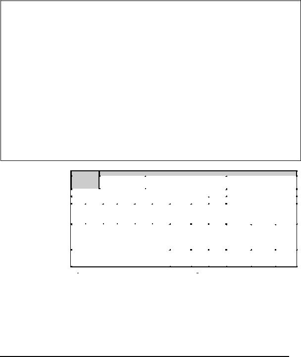
This chapter describes the procedure for removing and replacing the field replaceable units (FRUs) in the PC. It may not be necessary to remove all the FRUs in order to replace one. The chart below provides a guide as to which other FRUs must be removed before a particular FRU can be removed. The numbers in the chart indicate the relevant section numbers in this manual.
In all cases when removing an FRU, the battery pack must also be removed. When repairing an FRU that is the potential cause of a computer fault, use the chart to determine the order in which FRUs need to be removed.
4.3 |
|
|
4.2 Battery pack |
|
|
|
|
|
|
|
|
|
|
||
PC card |
|
|
|
|
|
|
|
|
|
|
|
|
|
|
|
SD memory |
|
|
|
|
|
|
|
|
|
|
|
|
|
||
|
|
|
|
|
|
|
|
|
|
|
|
|
|||
card |
|
4.6 Memory module |
|
4.7 HDD |
|
|
|
|
|
|
|
||||
|
|
|
|
|
|
|
|
|
|
|
|
|
|
|
|
|
|
|
|
|
|
|
|
|
|
|
|
|
|
|
|
4.4 Keyboard |
|
|
|
|
|
|
|
|
|
|
|
|
|
||
|
|
|
|
|
|
|
|
|
|
|
|
4.19 |
|
|
|
|
|
|
|
|
|
|
|
|
|
|
|
|
|
||
4.8 Base cover assembly |
|
|
|
|
|
|
|
LCD/FL inverter |
|
|
|||||
|
|
|
|
|
|
|
|
|
|
|
|
|
|
|
|
|
|
|
|
|
|
|
|
|
|
|
|
|
|
|
|
4.9 |
|
4.10 |
|
4.6 |
4.12 |
4.13 |
|
4.14 |
4.18 |
4.17 |
|
|
|
|
|
Mini |
|
MDC |
|
FAN/ |
RTC |
Blue |
|
Hinge |
Pen |
Second |
|
|
|
|
|
PCI |
|
modem |
|
CPU |
battery |
tooth |
|
cable |
holder/ |
FAN |
|
|
|
|
|
|
|
|
|
|
|
module |
|
Battery |
|
|
|
|
|
|
|
|
|
|
|
|
|
|
|
|
lock/ |
|
|
|
|
|
|
|
|
|
|
|
|
|
|
|
Base |
|
4.5 |
|
|
|
|
|
|
|
|
|
|
|
|
|
|
|
|
|
|||
|
|
|
|
|
|
|
|
|
latch |
|
Touch |
|
|
|
4.22 |
4.15 System board |
|
|
|
|
assembly |
|
pad |
4.21 |
|
4.8 |
LCD |
||||
|
|
|
|
|
|
|
harness/ |
||||||||
|
|
|
|
|
|
|
|
|
|
|
|
Digitizer |
|
Application |
Hinge |
|
|
|
|
|
|
|
|
|
|
|
|
|
|
Switch/ |
assembly |
|
|
|
|
|
|
|
|
|
|
|
|
|
|
Power |
|
|
|
|
|
|
|
|
|
|
|
|
|
|
|
switch/ |
|
|
|
|
|
|
|
|
|
|
|
|
|
|
|
LCD latch |
|
|
|
|
|
|
|
|
|
|
|
|
|
4.24 |
|
4.23 |
|
4.16 Speaker/LED board |
|
|
|
|
|
|
|
|
assembly |
Hinge |
|||||
|
|
|
|
|
|
|
Florescent |
|
|||||||
|
|
|
|
|
|
|
|
|
Switch |
||||||
|
|
|
|
|
|
|
|
|
|
|
|
lamp |
|
|
|
|
|
|
|
|
|
|
|
|
|
|
|
|
|
board |
|
|
|
|
|
|
|
|
|
|
|
|
|
|
|
|
|
|
|
|
|
|
|
|
|
|
|
|
|
|
|
|
|
(Example)
Chart Notation
The chart shows the case for the following example:
Removing the system board
All FRUs down to the “4.9 Mini PCI” to “4.14 Hinge cable” units immediately above the system board must be removed.
Similarly, as this requires the removal of all the units from “4.3 PC card” to “4.8Base cover assembly” must be also removed.
4.34.2 Battery pack
PC card/ |
|
|
|
|
|
|
|
|
|
|
|
|
|
|
|
SD memory |
4.6 Memory module |
|
4.7 HDD |
|
|
|
|
|
|
|
|||||
card |
|
|
|
|
|
|
|
|
|
|
|
|
|
|
|
|
|
|
|
|
|
|
|
|
|
|
|
|
|
|
|
4.4 Keyboard |
|
|
|
|
|
|
|
|
|
|
|
|
|
||
|
|
|
|
|
|
|
|
|
|
|
|
4.19 |
|
|
|
4.8 Base cover assembly |
|
|
|
|
|
|
|
LCD/FL inverter |
|
|
|||||
|
|
|
|
|
|
|
|
|
|
|
|
|
|
|
|
4.9 |
|
4.10 |
|
4.6 |
4.12 |
4.13 |
|
4.14 |
4.18 |
4.17 |
|
|
|
|
|
Mini |
|
MDC |
|
FAN/ |
RTC |
Blue |
|
Hinge |
Pen |
Second |
|
|
|
|
|
PCI |
|
modem |
|
CPU |
battery |
tooth |
|
cable |
holder/ |
FAN |
|
|
|
|
|
|
|
|
|
|
|
module |
|
Battery |
|
|
|
|
|
|
|
|
|
|
|
|
|
|
|
|
lock/ |
|
|
|
|
|
|
|
|
|
|
|
|
|
|
|
Base |
|
4.5 |
|
|
|
4.22 |
|
|
|
|
|
|
|
|
|
latch |
|
|
|
|
||
|
|
|
|
|
|
|
|
|
|
Touch |
|
|
|
||
|
|
|
|
|
|
|
|
|
|
|
|
4.8 |
LCD |
||
|
|
|
|
|
|
|
|
|
assembly |
|
4.21 |
|
|||
|
|
|
|
|
|
|
|
|
|
pad |
|
||||
4.15 System board |
|
|
|
|
|
|
Application |
harness/ |
|||||||
|
|
|
|
|
|
|
Digitizer |
|
|||||||
|
|
|
|
|
|
|
|
|
|
|
|
|
Switch/ |
Hinge |
|
|
|
|
|
|
|
|
|
|
|
|
|
|
|
||
|
|
|
|
|
|
|
|
|
|
|
|
|
|
Power |
assembly |
|
|
|
|
|
|
|
|
|
|
|
|
|
|
switch/ |
|
|
|
|
|
|
|
|
|
|
|
|
|
4.24 |
|
LCD latch |
4.23 |
|
|
|
|
|
|
|
|
|
|
|
|
|
Hinge |
||
4.16 Speaker/LED board |
|
|
|
|
|
|
|
Florescent |
|
assembly |
|||||
|
|
|
|
|
|
|
|
Switch |
|||||||
|
|
|
|
|
|
|
|
|
|
|
|
lamp |
|
|
|
|
|
|
|
|
|
|
|
|
|
|
|
|
|
board |
|
|
|
|
|
|
|
|
|
|
|
|
|
|
|
|
|
Portege M200 Maintenance Manual (960-457) |
4-1 |

4 Replacement Procedures |
4.1 Overview |
Safety Precautions
Please read the following safety instructions before disassembling the computer and always follow the instructions while working on the computer.
Danger: 1. In the case of the battery, always use authentic parts or equivalent parts approved by Toshiba. Other batteries may have different specifications that are incompatible with the computer and may result in fire or explosion.
Due to the risk of alkali fluid leaks, never attempt to heat or disassemble the battery. Similarly, due to the risk of explosion, never expose the battery to flame.
2.Some parts including the power supply and FL inverter generate high voltages. If you need to turn on the power while disassembling the computer, do not touch any connectors or other components due to the risk of electric shock. Also, do not disassemble individual parts when performing routine maintenance.
Warning:1. To prevent electric shock, turn off the power and unplug the AC adapter from the power source.
2.As the battery installed to the computer is typically already charged, the risk of electric shock remains even when the AC adapter is unplugged from the socket. To prevent electric shock, always take off any metal jewelry or accessories such as necklaces, bracelets or rings before working on the computer. Never work with wet or moist hands.
3.Take care not to injury yourself on any edges or corners.
Caution: 1. Confirm that replacement parts have compatible specifications before replacing on the computer. Never use incorrect parts as these may cause faults on the computer.
2.To prevent internal damage such as short circuits or burning, do not allow any screws, paper clips, or other metal objects to fall into the computer. When removing screws, always replace with the same size screw. Ensure that all screws are fully tightened. Loose screws may result in short circuits leading to overheating, smoke or flame.
3.To prevent electric shock, check that you have disconnected all cables from a part before removing the part.
4.When connecting to the AC power supply, use only an AC adapter and cable approved by Toshiba.
5.To prevent electric shock, ensure that all replacement parts are compatible with the computer and that all cables and connectors are securely connected.
4-2 |
Portege M200 Maintenance Manual (960-457) |

4.1 Overview |
4 Replacement Procedures |
Before You Begin
Take note of the following points before starting work. Always remove the AC adapter and battery pack before commencing any of the procedures. The procedure for removing the battery pack is described in section “4.2.1 Battery Pack”.
1.Do not disassemble the computer unless it is operating abnormally.
2.Use the designated tools.
3.Ensure that the environment for working on and storing parts does not contain any of the following.
Dust or dirt
Static electricity
Extremely hot, cold, or humid conditions
4.Perform the diagnostic tests described in Chapter 2 to determine which FRU is the cause of the fault.
5.Do not perform any unnecessary work. Always work in accordance with the disassembly and re-assembly procedures in this manual.
6.Keep parts removed from the computer in a safe place away from the computer where they will not be damaged or interfere with your work.
7.Disassembling requires the removal of a large number of screws. Keep removed screws in a safe place such that you can determine which screws belong to which part.
8.When reassembling, ensure that you use the correct screws and fit parts in the correct position. Screw sizes are noted in the text and figures.
9.As all parts have sharp edges and corners, take care not to cut yourself.
10.After replacing an FRU, check that the computer and replaced part operate correctly.
Portege M200 Maintenance Manual (960-457) |
4-3 |

4 Replacement Procedures |
4.1 Overview |
Disassembly Procedures
Three main types of cable connector are used.
Pressure plate connector
Spring connector
Normal pin connector
When disconnecting a pressure plate connector, draw the tab on one side of the plastic pressure plate on the connector and pull the cable out from the connector. When reconnecting a cable to a pressure plate connector, draw enough the pressure plate and insert the cable into the connector. Press both sides of the pressure plate such that both sides of the plate and connector are at the same height and that the cable is fixed in the correct position. Pull the cable to ensure that it is securely connected. If the cable is disconnected from the connector, reconnect it making sure that you draw enough the pressure plate to insert fully the cable.
For spring connectors, lifting up the stopper frees the cable and allows it to be pulled out. To reconnect, hold the stopper in the up position and insert the cable, then lower the stopper to secure the cable.
Normal pin connectors are used for all other cables. Simply pull out or push in these connectors to disconnect or reconnect.
Pressure plate connector |
Spring connector |
4-4 |
Portege M200 Maintenance Manual (960-457) |
4.1 Overview |
4 Replacement Procedures |
Assembly Procedure
After the computer has been disassembled and the part that caused the fault has been repaired or replaced, the computer must be reassembled.
Take note of the following general points when assembling the computer.
Take your time and follow the instructions carefully. Hurrying the assembly work will only introduce new problems.
Check that all cables and connectors are securely connected.
Before fastening FRUs or other parts in place, ensure that no cables are caught on screws or the FRU.
Check that all latches are securely closed.
Ensure that you have installed all FRUs correctly and do not have any screws left over. Using an incorrect screw may damage the thread or screw head and result in the FRU not being securely fastened in place.
After installing FRUs, check that the computer operates correctly.
Tools and Equipment
For your safety and the safety of the people around you, it is important that you use Electrostatic Discharge (ESD) equipment. Correctly utilizing of the equipment increases the percentage of successful repairs and saves on the cost of damaged or destroyed parts. The following equipment is required for disassembly and assembly.
One Philips screwdriver with type 0 bit (for THIN HEAD screws)
One Philips screwdriver with type 1 bit (for screws other than above)
Tweezers (for lifting screws)
ESD mats (lay on work table or floor)
An ESD wrist strap and heel grounder
Anti-static carpet or flooring
A pair of needle-nose pliers
Air-ionizers in highly static sensitive areas
Antenna coaxial cable disconnector
Portege M200 Maintenance Manual (960-457) |
4-5 |

4 Replacement Procedures |
4.1 Overview |
Screw Tightening Torque
Use the following torque when tightening screws.
Caution: Overtightening may damage screws or parts. Undertightening may allow screws to loosen (and possibly fall out) causing a short circuit or other damage.
Note: To tighten screws quickly and accurately, an electric screwdriver is recommended.
M2 (2mm) |
0.167 N•m (1.7 kgf •cm) |
|
|
M2.5 (2.5mm) |
0.294 N•m(3.0 kgf•cm) |
|
M3 (3mm) |
0.549 N•m(5.6 kgf•cm) |
Note: To prevent damage to THIN HEAD screws, use type 0 pit philips screwdriver. Use, however, the PH point size “1” screwdriver for screws fixing the expansion memory slot cover and the keyboard.. Press along the axis of the screwdriver while turning the screw. This is because the contact area between the screw and driver is less than for a pan head screw (standard pan-shaped screw head).
Grip Color
Some screws have a colored grip area to help you determine the length of the screw.
Even numbered length screws: Brown |
|
Odd numbered length screws: White |
|
Special length screw: Blue |
|
“Special length screw” means screws whose length is indicated |
Grip area |
in an integral number to the first decimal places such as 2.5 mm, |
|
2.6 mm and so on. |
|
4-6 |
Portege M200 Maintenance Manual (960-457) |

4.1 Overview |
4 Replacement Procedures |
Screw Notation
To make maintenance of the computer easier, markings of the kinds of the screws including the types and lengths of the screws are indicated on the computer body.
Format:
Screw shape + Screw length (mm)
Screw shape
B: Bind screw
F: Flat head screw
S:Super thin head screw
T:Tapping screw
U:Other screws (Unique screws: pan head, stud, etc.)
Example: B6 ... 6mm BIND screw
Portege M200 Maintenance Manual (960-457) |
4-7 |

4 Replacement Procedures |
4.2 Battery pack |
4.2Battery pack
Removing the battery pack
The following describes the procedure for removing the battery pack. (See Figure 4-1.)
Caution: Take care not to short circuit the terminals when removing the battery pack. Similarly, do not drop, knock, scratch, disassemble, twist, or bend the battery pack.
1.Turn off the power of the computer.
2.Disconnect the AC adapter and all other external devices from the computer.
3.Turn the computer upside down.
4.Release the battery lock switch.
5.Slide the battery latch in the direction indicated by the arrow to loosen the lock. Pull out the battery to remove.
Battery pack
Battery latch
Battery lock switch
Figure 4-1 Removing the battery pack
Note: Dispose of the used battery pack in accordance with the laws and ordinances of your local authority.
4-8 |
Portege M200 Maintenance Manual (960-457) |

4.2 Battery pack |
4 Replacement Procedures |
Installing the battery pack
The following describes the procedure for installing the battery pack. (See Figure 4-1.)
Caution: There is a danger that the lithium ion battery pack may explode if not fitted, operated, handled, or disposed correctly. Dispose of the used batteries pack in accordance with the laws and ordinances of your local authority. Use only the batteries approved by Toshiba.
Note: Check visually the battery terminals and clean off any dirt with a dry cloth.
1.Turn off the power of the computer.
2.Disconnect the AC adapter and all other external devices from the computer.
3.Inset the connector of the battery to the connector of the computer. Press the battery pack until the battery is locked.
4.Secure the battery lock.
Portege M200 Maintenance Manual (960-457) |
4-9 |

4 Replacement Procedures |
4.3 PC Card/SD memory card |
4.3PC Card/SD memory card
4.3.1 PC Card
Removing the PC Card
The following describes the procedure for removing the PC card. (See Figure 4-2.)
Caution: Insert or remove the PC Card in accordance with any instructions in the PC Card manual or the manuals of the computer system you are using.
1.Push the ejection button. It will pop out when you release it. Press it once more to eject the PC Card.
2.Pull out the and remove it.
Eject button
 PC card
Figure 4-2 Removing the PC card
Installing the PC Card
The following describes the procedure for installing the PC card. (See Figure 4-2.)
1.Make sure the eject button does not stick out.
2.Insert the PC Card and press it until it is securely connected.
4.3.2SD memory card
Removing the SD memory card
The following describes the procedure for removing the SD memory card. (See Figure 4- 3.)
4-10 |
Portege M200 Maintenance Manual (960-457) |
4.3 PC Card/SD memory card |
4 Replacement Procedures |
Caution: Insert or remove the SD card in accordance with any instructions in the SD card manual or the manuals of the computer system you are using.
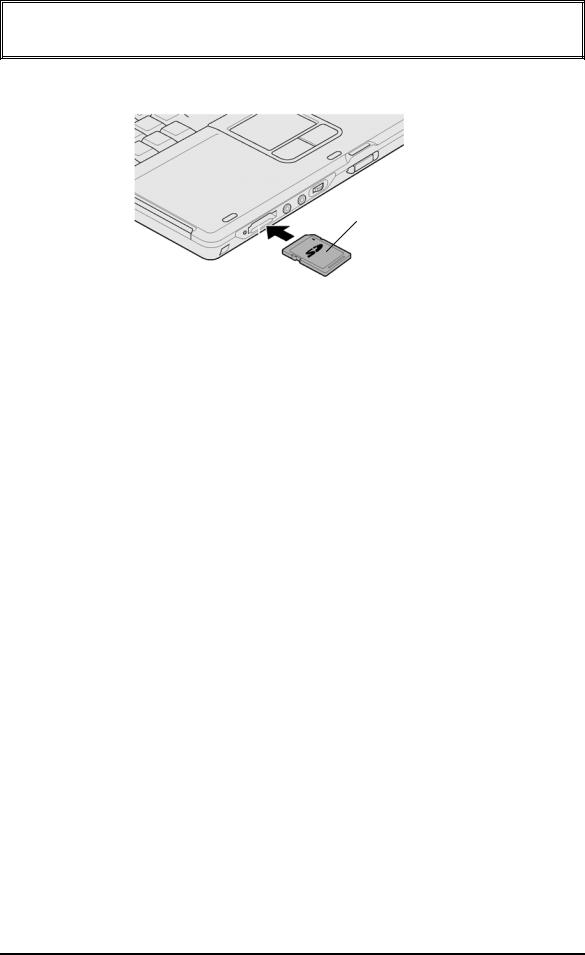
1.Push the SD memory card. It will pop out partly when you release, so pull out the card.
SD memory card
Figure 4-3 Removing the SD memory card
Installing the SD memory card
The following procedure describes the procedure for installing the SD memory card. (See Figure 4-3.)
1.Insert the SD memory card and press it until it securely connected.
Portege M200 Maintenance Manual (960-457) |
4-11 |

4 Replacement Procedures |
4.4 Keyboard |
4.4Keyboard
Removing the keyboard
The following describes the procedure for removing the keyboard. (See Figure 4-4.)
1.Open the display.
2.Insert your nails in the slot of both sides of the keyboard holder and lift it up to remove.
3.Remove the following screws securing the keyboard.
• M2.5×2.8B |
FLAT BIND screw |
x2 |
M2.5 x 2.8B FLAT BIND
Keyboard holder
PJ3230
Figure 4-4 Removing the keyboard
4.Lift the top edge of the keyboard and bring the edge to the front to lay on the computer. Unlock the connector and disconnect the flexible keyboard cable from the connector on the system board.
5.Remove the keyboard.
4-12 |
Portege M200 Maintenance Manual (960-457) |

4.4 Keyboard |
4 Replacement Procedures |
Installing the keyboard
The following describes the procedure for installing the keyboard. (See Figure 4-4.)
1.Put the keyboard on the palm rest as its face is down. Connect the flexible keyboard cable to PJ3230 on the system board and lock the connector.
2.Hook the bottom edge of the keyboard to the palm rest. Place the keyboard on the computer and secure it with the following screws.
• M2.5×2.8B |
FLAT BIND screw |
x2 |
3. Install the keyboard holder.
Portege M200 Maintenance Manual (960-457) |
4-13 |
4 Replacement Procedures |
4.5 Touch pad |
4.5Touch pad
Removing the touch pad
The following describes the procedure for removing the touch pad. (See Figure 4-5.)
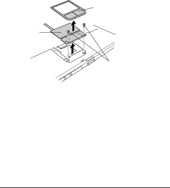
1.Disconnect the flat cable from the connector on the system board.
2.Pull the touch pad holder slantwise from the computer.
3.Remove the following screws securing the touch pad.
• M2.5×3B S-THIN screw x2
4.Remove the touch pad from the computer.
5.Disconnect the flat cable from the touch pad.
Touch Pad Holder
Touch Pad
M2.5x3B S-THIN
Figure 4-5 Removing the Touch Pad
Installing the touch pad
The following describes the procedure for installing the touch pad (See Figure 4-5.).
1.Connect the flat cable to the touch pad.
2.Install the touch pad on the computer.
3.Secure the touch pad with the following screws.
• M2.5×3B S-THIN screw x2
4.Insert the touch pad holder into the touch pad slot slantwise.
5.Connect the flat cable to the connector PJ3240 on the system board.
4-14 |
Portege M200 Maintenance Manual (960-457) |
4.6 Memory module |
4 Replacement Procedures |
4.6Memory module
Caution: The power must be turned off when you remove the memory module. Removing a memory module with the power on risks damaging the module or the computer itself.
Do not touch the memory module terminals. Any dirt on the terminals may cause memory access problems.
Never press hard or bend the memory module.
Removing the memory module
To remove the memory module(s), confirm that the computer is in boot mode. Then perform the following procedure. (See Figure 4-6.)
1.Turn the computer upside down.
2.Loosen the screw with e-ring fixing the memory slot cover.
3.Remove the memory slot cover.
4.Open the left and right latches and remove the memory module(s).
Screw with e-ring
 Memory slot cover
|
|
Slot A |
|
|
Slot B |
Memory module |
Figure 4-6 Removing the memory module
Portege M200 Maintenance Manual (960-457) |
4-15 |

4 Replacement Procedures |
4.6 Memory module |
Installing the memory module
To install the memory module(s), confirm that the computer is in boot mode. Then perform the following procedure. (See Figure 4-6.)
1.Insert the memory module into the connector of the computer slantwise (terminal side first) and press it to connect firmly.
Caution: The power must be turned off when you insert the memory module. Inserting a memory module with the power on risks damaging the module or the computer itself.
Never press hard or bend the memory module.
When installing a memory module, be sure to install the memory module into the slot B.
2.Install the memory slot cover.
3.Secure the screw with e-ring to fix the memory slot cover.
4-16 |
Portege M200 Maintenance Manual (960-457) |
4.7 HDD |
4 Replacement Procedures |
4.7HDD
Removing the HDD
The following describes the procedure for removing the HDD. (See Figure 4-7 to 4-8.)
Caution: Take care not to press on the top or bottom of the HDD. Pressure may cause data loss or damage to the device.
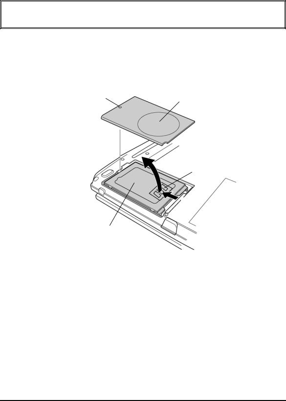
1.Turn the computer upside down.
2.Loosen the screw with e-ring securing the HDD slot cover and remove the cover.
3.Hold the HDD holder tab and pull the HDD assembly to the arrow direction (1) in the figure below and remove the HDD assembly.
Screw with e-ring
HDD slot cover
HDD holder tab
(1)
HDD assembly
Figure 4-7 Removing the HDD cover
Portege M200 Maintenance Manual (960-457) |
4-17 |
Loading...