


 Loading...
UM-TS03 -E032
PROGRAMMABLE CONTROLLER
PROSEC T3H
USER’S MANUAL
TOSHIBA CORPORATION
Important Information
Misuse of this equipment can result in property damage or human injury. Because controlled system applications vary widely, you should satisfy yourself as to the acceptability of this equipment for your intended purpose.
In no event will Toshiba Corporation be responsible or liable for either indirect
or consequential damage or injury that may result from the use of this equipment.
No patent liability is assumed by Toshiba Corporation with respect to use of information, illustrations, circuits, equipment or examples of application in this publication.
Toshiba Corporation reserves the right to make changes and improvements to this publication and/or related products at any time without notice. No obligation shall be incurred other than as noted in this publication.
This publication is copyrighted and contains proprietary material. No part of this book may be reproduced, stored in a retrieval system, or transmitted, in any form or by any means electrical, mechanical, photocopying, recording, or otherwise without obtaining prior written permission from Toshiba Corporation.
© TOSHIBA Corporation 1996. All rights reserved
Ethernet is a registered trademark of Xerox Corporation.
PROSEC and TOSLINE are registered trademarks of TOSHIBA Corporation.
Publication number: UM-TS03 -E032 1st edition June 1996

Safety Precautions
This manual is prepared for users of Toshiba’s Programmable Controller T3H.
Read this manual thoroughly before using the T3H. Also, keep this manual and related manuals so that you can read them anytime while the T3H is in operation.
General Information
1.The T3H has been designed and manufactured for use in an industrial environment. However, the T3H is not intended to be used for systems which may endanger human life. Consult Toshiba if you intend to use the T3H for a special application, such as transportation machines, medical apparatus, aviation and space systems, nuclear controls, submarine systems, etc.
2.The T3H has been manufactured under strict quality control. However, to keep safety of overall automated system, fail-safe systems should be considered outside the T3H.
3.In installation, wiring, operation and maintenance of the T3H, it is assumed that the users have general knowledge of industrial electric control systems.
If this product is handled or operated improperly, electrical shock, fire or damage to this product could result.
4.This manual has been written for users who are familiar with Programmable Controllers and industrial control equipment. Contact Toshiba if you have any questions about this manual.
5.Sample programs and circuits described in this manual are provided for explaining the operations and applications of the T3H. You should test completely if you use them as a part of your application system.
Hazard Classifications
In this manual, the following two hazard classifications are used to explain the safety precautions.
!WARNING
!CAUTION
Indicates a potentially hazardous situation which, if not avoided, could result in death or serious injury.
Indicates a potentially hazardous situation which, if not avoided, may result in minor or moderate injury. It may also be used to alert
against unsafe practices.
Even a precaution is classified as CAUTION, it may cause serious results depending on the situation. Observe all the safety precautions described on this manual.
User’s Manual 1

Safety Precautions
Safety Precautions
Installation:
!CAUTION
1.Excess temperature, humidity, vibration, shocks, or dusty and corrosive gas environment can cause electrical shock, fire or malfunction. Install and use the T3H and in the environment described in the T3 User’s Manual - Hardware.
2.Improper installation directions or insufficient installation can cause fire or the units to drop. Install the T3H in accordance with the instructions described in the T3 User’s Manual - Hardware -.
3.Turn off power before installing or removing any units, modules or terminal blocks. Failure to do so can cause electrical shock or damage to the T3H and related equipment.
4.Entering wire scraps or other foreign debris into to the T3H and related equipment can cause fire or malfunction. Pay attention to prevent entering them into the T3H and related equipment during installation and wiring.
Wiring:
!CAUTION
1.Turn off power before wiring to minimize the risk of electrical shock.
2.Exposed conductive parts of wire can cause electrical shock. Use crimp-style terminals with insulating sheath or insulating tape to cover the conductive parts. Also close the terminal covers securely on the terminal blocks when wiring has been completed.
3.Operation without grounding may cause electrical shock or malfunction. Connect the ground terminal on the T3H to the system ground.
4.Applying excess power voltage to the T3H can cause explosion or fire. Apply power of the specified ratings described in the T3 User’s Manual - Hardware.
5.Improper wiring can cause fire, electrical shock or malfunction. Observe local regulations on wiring and grounding.
2 PROSEC T3H

Safety Precautions
Operation:
!WARNING
1.Configure emergency stop and safety interlocking circuits outside the T3H. Otherwise, malfunction of the T3H can cause injury or serious accidents.
!CAUTION
2.Operate the T3H and the related modules with closing the terminal covers. Keep hands away from terminals while power on, to avoid the risk of electrical shock.
3.When you attempt to perform force outputs, RUN/HALT controls, etc. during operation, carefully check for safety.
4.Turn on power to the T3H before turning on power to the loads. Failure to do so may cause unexpected behavior of the loads.
5.Set operation mode switches of the T3H and I/O modules. Improper switch settings may cause malfunction of the T3H and related equipment.
6.Do not use any modules of the T3H for the purpose other than specified. This can cause electrical shock or injury.
7.Configure the external circuit so that the external power required for output modules and power to the loads are switched on/off simultaneously.
Also, turn off power to the loads before turning off power to the T3H.
8.Install fuses appropriate to the load current in the external circuits for the relay output modules. Failure to do so can cause fire in case of load over-current.
9.Check for proper connections on wires, connectors and modules. Insufficient contact can cause malfunction or damage to the T3H and related equipment.
10.Turn off power immediately if the T3H is emitting smoke or odor. Operation under such condition can cause fire or electrical shock.
Also unauthorized repairing will cause fire or serious accidents. Do not attempt to repair. Contact Toshiba for repairing.
User’s Manual 3

Safety Precautions
Maintenance:
!CAUTION
1.Do not charge, disassemble, dispose in a fire nor short-circuit the batteries. It can cause explosion or fire. Observe local regulations for disposal of them.
2.Turn off power before removing or replacing units, terminal blocks or wires. Failure to do so can cause electrical shock or damage to the T3H and related equipment.
3.Replace a blown fuse with a specified one. Failure to do so can cause fire or damage to the T3H.
4.Perform daily checks, periodical checks and cleaning to maintain the system in normal condition and to prevent unnecessary troubles.
5.Check by referring “Troubleshooting” section of the T3 User’s Manual - Hardware, when operating improperly. Contact Toshiba for repairing if the T3H or related equipment is failed. Toshiba will not guarantee proper operation nor safety for unauthorized repairing.
6.The contact reliability of the relays used in the relay output module will reduce if the switching exceeds the specified life. Replace the module if exceeded.
7.Replace the battery every 2 years to maintain the T3H’s program and data normally.
8.Do not modify the T3H and related equipment in hardware nor software. This can cause fire, electrical shock or injury.
9.Pay special attention for safety if you attempt to measure circuit voltage at the T3H’s terminal.
10.Turn off power before replacing modules. Failure to do so can cause electrical shock or damage to the T3H and related equipment.
If you attempt to replace an I/O module while power on (by using on-line I/O replacement function), carefully check for safety.
4 PROSEC T3H
Safety Precautions
Safety Label
The safety label as shown on the right is attached to the power terminal of the T3H.
Remove the mount paper before wiring.
Peel off the label from the mount paper and stick it near the power terminals where it can be readily seen.
Contact Toshiba if the label is damaged.
! CAUTION
Do not touch terminals while power on.
Hazardous voltage can shock, burn or cause death. Do not touch terminals while power on.
Read related manual thoroughly for safety. Stick this seal on unit or near unit.
Take off this sheet before wiring.
User’s Manual 5

About This Manual
About This Manual
The T3H is a high speed and large capacity version of the T3. All the hardware components used for the T3 system, i.e. rack, power supply module, I/O modules, etc., are used with the T3H CPU. Regarding software function, the T3H has all the T3’s functions and has some expanded functions.
This manual explains the expanded functions of the T3H and functional differences between the T3H and the T3. Therefore, for your better understanding of the T3H, read the following T3 manuals at first to understand the T3 system, then read this manual.
T3 manuals: |
|
|
|
T3 |
User’s Manual − |
Hardware |
UM-TS03 -E002 |
T3 |
User’s Manual − |
Function |
UM-TS03 -E003 |
T-series Instruction Set |
UM-TS03 -E004 |
||
T-series Computer Link Operation Manual |
UM-TS03 -E008 |
||
T3 |
Analog Input Module (AD368) |
UM-TS03 -E016 |
|
T3 |
Analog Output Module (DA364/DA374) |
UM-TS03 -E017 |
|
T3 |
Pulse Input Module (PI312) |
UM-TS03 -E018 |
|
T3 |
ASCII Module (AS311) |
UM-TS03 -E020 |
|
Terminology
The following is a list of abbreviations and acronyms used in this manual.
s |
microsecond |
ASCII |
American Standard Code For Information Interchange |
AWG |
American Wire Gage |
BCC |
Block Check Code |
CPU |
Central Processing Unit |
EEPROM |
Electrically Erasable Programmable Read Only Memory |
H |
hexadecimal (when it appears in front of an alphanumeric string) |
I/O |
Input/Output |
LED |
Light Emitting Diode |
LSB |
Least Significant Bit |
ms |
millisecond |
MSB |
Most Significant Bit |
RAM |
Random Access Memory |
ROM |
Read Only Memory |
SFC |
Sequential Function Chart |
Vac |
AC voltage |
Vdc |
DC voltage |
|
|
|
|
6 PROSEC T3H

|
|
Contents |
Contents |
|
|
Safety Precautions .................................................................................. |
1 |
|
About This Manual ...................................................................................... |
6 |
|
1. |
T3H Overview ................................................................................. |
9 |
1.1 |
Introducing the T3H .......................................................................... |
10 |
1.2 |
Differences between T3H and T3 .................................................... |
11 |
1.3 |
T3H components .............................................................................. |
12 |
1.4 |
Specifications ................................................................................... |
20 |
2. |
Expanded Functions ..................................................................... |
27 |
2.1 |
System operation ............................................................................. |
28 |
2.1.1 |
Auto-RUN / Standby selection ....................................................... |
28 |
2.1.2 |
Timer interrupt interval ................................................................... |
28 |
2.1.3 |
Saving the sampling trace condition .............................................. |
29 |
2.2 |
Expanded registers ........................................................................... |
30 |
2.2.1 |
External I/O register ...................................................................... |
30 |
2.2.2 |
Auxiliary register ............................................................................ |
30 |
2.2.3 |
Timer ............................................................................................. |
31 |
2.2.4 |
Link register ................................................................................... |
31 |
2.2.5 |
File register .................................................................................... |
34 |
2.2.6 |
Special register .............................................................................. |
34 |
2.3 |
Network support function .................................................................. |
38 |
2.3.1 |
IC memory card data access through computer link ...................... |
38 |
2.3.2 |
TOSLINE-S20LP (loop) support .................................................... |
41 |
2.3.3 |
Ethernet support ........................................................................... |
42 |
2.4 |
Instructions ....................................................................................... |
43 |
2.4.1 |
Double-word multiplication and division (D/ ) .............................. |
44 |
2.4.2 |
Essential PID (PID3) .................................................................... |
46 |
2.4.3 |
Floating point essential PID (FPID3) ............................................. |
51 |
2.4.4 |
Expanded data transfer (XFER) .................................................... |
56 |
2.4.5 |
Network data send (SEND) .......................................................... |
62 |
2.4.6 |
Network data receive (RECV) ....................................................... |
66 |
User’s Manual 7
8 PROSEC T3H
Section 1
T3H Overview
1.1Introducing the T3H, 10
1.2Differences between T3H and T3, 11
1.3T3H components, 12
1.4Specifications, 20
User’s Manual 9

1. T3H Overview
1.1 Introducing the T3H
The T3H is a high performance large scale programmable controller.
Program memory capacity:
The T3H is available in two CPU types, PU325H and PU326H. Each type has the following user program memory capacity.
PU325H: 32 k steps PU326H: 64 k steps
I/O points:
The T3H can handle up to 76 I/O modules in its local configuration. And the T3H has 512 words of external I/O register (data memory).
If all the I/O modules are discrete I/Os, the T3H can control up to 4864 points. (64 points × 76 = 4864 points)
If all the I/O modules are analog I/Os, the T3H can control up to 512 channels of analog signals.
High speed processing:
A standard 16-bit micro processor and a special designed language processor are used in the T3H CPU. This dual-processor architecture provides high speed processing.
0.09 |
µ s/contact |
0.18 |
µ s/coil |
0.54 |
µ s/16-bit transfer |
0.90 |
µ s/16-bit addition |
Multitasking:
The T3H supports the multitask processing. By using this function, suitable control interval for a target application can be obtained.
1 × internal timer interrupt (interval setting: 1 to 1000 ms, 1 ms units) 8 × I/O interrupts (activated by external events)
1 × main program (core of the user program)
4 × sub-programs (activated from other tasks and executed as back-ground job)
Multiple programming languages:
The T3H supports two types of programming languages, i.e. ladder diagram and SFC (Sequential Function Chart). The ladder diagram is suited for logic control, and the SFC is suited for sequential control. These languages can be used in mixture.
High performance software:
The T3H supports 24 basic ladder instructions and 204 function instructions. Floating points data processing is also available. The T3H can be applied to complex control applications.
Network support:
The T3H can be connected to work-stations/personal-computers through Ethernet. Peer-to-peer communications between two T3H’s via Ethernet is also available. For high-speed control-data linkage, TOSLINE-S20/F10 can be used.
10 PROSEC T3H

1. T3H Overview
1.2 Differences between T3H and T3
The table below summarizes the differences between the T3H and T3. All other functions supported by the T3 can also be supported by the T3H as same.
|
|
Item |
T3H |
T3 |
|
|
Program memory capacity |
32 k steps (PU325H) |
32 k steps |
||
|
|
|
64 k steps (PU326H) |
(PU315 and PU325) |
|
|
Built-in EEPROM |
Yes |
No (PU315) |
||
|
|
|
(PU325H and PU326H) |
Yes (PU325) |
|
|
Programming instructions |
All T3’s instructions plus |
− |
||
|
|
|
FUN042 D / |
|
|
|
|
|
FUN156 PID3 |
|
|
|
|
|
FUN232 FPID3 |
|
|
|
|
|
FUN239 SEND |
|
|
|
|
|
FUN240 RECV |
|
|
|
Execution speed (µ s) |
0.09 / contact |
0.15 / contact |
||
|
|
|
0.18 / coil |
0.3 / coil |
|
|
|
|
0.9 / addition |
1.5 / addition |
|
|
Max. number of I/O modules |
76 modules |
43 modules |
||
|
supported in local |
(when IF321 is used) |
|
|
|
|
System |
Timer interrupt interval |
1 to 1000 ms, 1 ms units |
2 to 1000 ms, 1 ms units |
|
|
operation |
setting |
|
|
|
|
|
Auto-RUN / standby |
Software setting |
Hardware switch |
|
|
|
selection |
(system information) |
(RAM/ROM switch) |
|
|
User data |
External I/O |
8192 points / 512 words |
4096 points / 256 words |
|
|
|
(X/XW, Y/YW) |
|
|
|
|
|
Auxiliary register |
16000 points / |
8192 points / 512 words |
|
|
|
(R/RW) |
1000 words |
|
|
|
|
Special register |
4096 points / 256 words |
Same as left |
|
|
|
(S/SW) |
|
|
|
|
|
Timer (T./T) |
1000 points |
512 points |
|
|
|
|
(proportion of 0.1s and |
(T000 - T063: 0.1s) |
|
|
|
|
0.01s timer is user |
(T064 - T511: 0.01s) |
|
|
|
|
definable) |
|
|
|
|
Counter (C./C) |
512 points |
Same as left |
|
|
|
Data register (D) |
8192 words |
Same as left |
|
|
|
Link register (Z/W) |
16000 points / |
8192 points / |
|
|
|
(for TOSLINE-S20) |
2048 words |
1024 words |
|
|
|
|
(bit access available for |
(bit access available for |
|
|
|
|
leading 1000 words) |
leading 512 words) |
|
|
|
Link register (L/LW) |
4096 points / 256 words |
Same as left |
|
|
|
(for TOSLINE-F10) |
|
|
|
|
|
File register (F) |
32768 words |
8192 words |
|
|
|
Index register |
3 words |
Same as left |
|
|
|
(I, J, K) |
|
|
|
|
Programming |
tool |
T-PDS |
T-PDS and HP911 |
|
|
Networking |
|
Ethernet, |
TOSLINE-S20, |
|
|
|
|
TOSLINE-S20, |
TOSLINE-F10, |
|
|
|
|
TOSLINE-F10, |
RS-485 computer link |
|
|
|
|
RS-485 computer link |
|
|
|
|
|
|
|
|
User’s Manual 11

1.T3H Overview
1.3T3H components
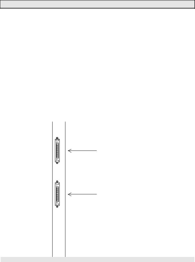
(1)CPU module
Two types of T3H CPU modules are available.
Type |
Description |
PU325H |
EEPROM + RAM (battery backed), User program 32 k steps, |
|
Ladder diagram and SFC |
PU326H |
EEPROM + RAM (battery backed), User program 64 k steps, |
|
Ladder diagram and SFC |
PU325H
RUN 
FAULT 
 BATT I/O
RAM |
ROM |
RUN
HALT  P-RUN
P-RUN
BATTERY
PROG
CARD
LINK
EJECT
Product identification
Status LEDs
RAM/ROM switch
Mode control switch (HALT/RUN/P-RUN)
Battery cover
Programmer port
(RS-232C, D-Sub 9-pin female connector)
IC memory card slot
Computer link port
(RS-485, D-Sub 15-pin female connector)
Module fixing screw
The external feature of the T3H CPU is the same as the T3 CPU except for the product identification.
12 PROSEC T3H

|
|
|
|
1. T3H Overview |
|
|
Status LEDs: |
|
|
||
|
RUN |
Lit |
|
User program is being executed (RUN mode) |
|
|
(green) |
Blink |
|
User program execution is stopped (HOLD mode) |
|
|
|
Not lit |
|
User program execution is stopped (HALT or ERROR mode) |
|
|
FAULT |
Lit |
|
CPU or program error |
|
|
(red) |
Blink |
|
Hardware initialization error |
|
|
|
Not lit |
|
Normal |
|
|
I/O |
Lit |
|
I/O error |
|
|
(red) |
Blink |
|
Hardware initialization error |
|
|
|
Not lit |
|
Normal |
|
|
BATT |
Lit |
|
Battery voltage is normal |
|
|
(green) |
Not lit |
|
Battery voltage is low (battery replacement is required) |
|
|
RAM/ROM switch: |
|
|
||
|
RAM |
User program stored in RAM is used. |
|
||
|
|
(Program transfer from EEPROM to RAM is not executed) |
|
||
|
ROM |
At the beginning of RUN mode, user program stored in EEPROM is transferred to |
|
||
|
|
RAM. (It is called Initial load) |
|
||
|
|
If an IC memory card which contains user program has been installed, the IC |
|
||
|
|
memory card becomes transfer source. |
|
||
|
|
(If mode control switch is in P-RUN, the initial load is not executed) |
|
||
Note) In case of T3, the RAM/ROM switch has the function of auto-RUN/standby selection in addition to the initial load selection.
However, in case of T3H, the RAM/ROM switch only has the function of initial load selection as mentioned above.
Mode control switch:
HALT |
User program execution is stopped. (HALT mode) |
|
Normally, programming is performed in the HALT mode. |
|
T3H operation mode control by programmer is not allowed. |
RUN |
T3H executes user program cyclically. (RUN mode) |
|
It is the normal switch position under operation. |
|
Even in the RUN mode, program changes are possible. However, saving into the |
|
EEPROM is available only in the HALT mode. |
|
T3H operation mode control by programmer is possible. |
P-RUN |
T3H executes user program cyclically. (RUN mode) |
|
User program and the leading 4 k words of D register (D0000 to D4095) are write- |
|
protected. |
|
T3H operation mode control by programmer is possible. |
Note) In case of T3, even in P-RUN, data writing into D0000 to D4095 by instruction is allowed except for some instructions.
However, in case of T3H, data writing into D0000 to D4095 by instruction is inhibited if in P-RUN.
User’s Manual 13
1. T3H Overview
Battery cover:
A battery has been installed inside this cover at the factory shipment. The battery keeps the RAM contents (user program and user data), and supports the clockcalendar operation during power off.
The same battery as the T3’s is used.
Programmer port:
The programmer (T-PDS) is connected to the T3H through this port. The same connection cable as the T3’s is used.
Computer link port:
The T3H CPU module has the computer link function as standard. This port is used to connect between T3H and a computer.
The T-series computer link protocol is supported by T3H.
IC memory card slot:
Optional IC memory card (type: ME914) can be used with the T3H.
By using the IC memory card, user program saving/loading or user data expansion is available.
NOTE For details of the operation mode and functions, refer to the T3 User’s Manual.
14 PROSEC T3H
1. T3H Overview
(2)Expansion interface module
The expansion interface modules for the T3, i.e. IF311, IF351, IF312, IF352 and IF353, are also used with the T3H. When the IF311 or IF312 is used with the T3H, up to three expansion units can be connected, as same as the T3.
On the other hand, the IF321 is a dedicated expansion interface module for the T3H. When the IF321 is used instead of the IF311, up to 6 expansion units can be connected. In the maximum configuration, the T3H can control up to 76 I/O modules.
Type |
|
|
|
Description |
Remarks |
IF321 |
|
For basic unit |
Standard expansion type. |
Only for T3H |
|
|
|
(2 channels) |
2 m max. between units, 6 m |
|
|
IF311 |
|
For basic unit |
max. in total cable length for each |
T3/T3H |
|
|
|
(1 channel) |
channel. |
common |
|
IF351 |
|
For expansion unit |
|
|
|
IF312 |
|
For basic unit |
Long-distance expansion type. |
|
|
IF352 |
|
For middle expansion |
40 m max. in cable length. |
|
|
|
|
unit |
(one channel only) |
|
|
IF353 |
|
For end expansion |
|
|
|
|
|
unit |
|
|
|
|
|
|
|
|
|
|
IF321 |
|
|
||
Channel 2 expansion (connected to the expansion #4)
CH2
Channel 1 expansion (connected to the expansion #1)
CH1
User’s Manual 15
1. T3H Overview
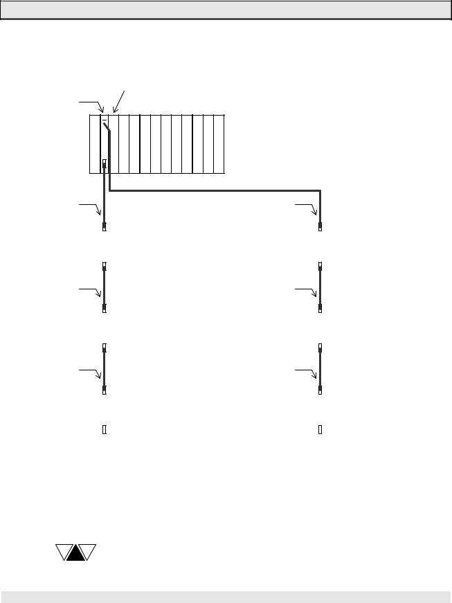
The figure below shows the T3H’s maximum expansion configuration.
T3H CPU
IF321
Basic unit
P 
 C I I I I I I I I I I
S I P / / / / / / / / / /
F U O O O O O O O O O O
CH1 |
|
|
|
|
|
|
|
|
|
|
CH2 |
||||
IF351 |
|
Expansion unit #1 |
|
|
|
||||||||||
|
|
|
|
|
|
|
|
||||||||
|
P |
|
I |
I |
I |
I |
I |
I |
I |
I |
I |
|
I |
I |
|
|
S |
I |
/ |
/ |
/ |
/ |
/ |
/ |
/ |
/ |
/ |
|
/ |
/ |
|
|
|
F |
O |
O |
O |
O |
O |
O |
O |
O |
O |
O |
O |
|
|
|
|
|
|
|
|
|
|
|
|
|
|
|
|
|
|
IF351 |
|
Expansion unit #2 |
|
|
||||||||||
|
P |
|
I |
I |
I |
I |
I |
I |
I |
I |
I |
|
I |
I |
|
S |
I |
/ |
/ |
/ |
/ |
/ |
/ |
/ |
/ |
/ |
|
/ |
/ |
|
|
F |
O |
O |
O |
O |
O |
O |
O |
O |
O |
O |
O |
|
|
|
|
|
|
|
|
|
|
|
|
|
|
|
|
IF351 |
|
Expansion unit #3 |
|
|
||||||||||
|
P |
|
I |
I |
I |
I |
I |
I |
I |
I |
I |
|
I |
I |
|
S |
I |
/ |
/ |
/ |
/ |
/ |
/ |
/ |
/ |
/ |
|
/ |
/ |
|
|
F |
O |
O |
O |
O |
O |
O |
O |
O |
O |
O |
O |
|
|
|
|
|
|
|
|
|
|
|
|
|
|
|
|
PS: |
Power supply module |
IF: |
Expansion interface module |
CPU: |
CPU module |
I/O: |
I/O module or |
|
data transmission module |
IF351 |
|
Expansion unit #4 |
|
|
||||||||||
|
|
|
|
|
|
|
||||||||
|
P |
|
I |
I |
I |
I |
I |
I |
I |
I |
I |
|
I |
I |
|
S |
I |
/ |
/ |
/ |
/ |
/ |
/ |
/ |
/ |
/ |
|
/ |
/ |
|
|
F |
O |
O |
O |
O |
O |
O |
O |
O |
O |
O |
O |
|
|
|
|
|
|
|
|
|
|
|
|
|
|
|
|
IF351 |
|
Expansion unit #5 |
|
|
||||||||||
|
P |
|
I |
I |
I |
I |
I |
I |
I |
I |
I |
|
I |
I |
|
S |
I |
/ |
/ |
/ |
/ |
/ |
/ |
/ |
/ |
/ |
|
/ |
/ |
|
|
F |
O |
O |
O |
O |
O |
O |
O |
O |
O |
O |
O |
|
|
|
|
|
|
|
|
|
|
|
|
|
|
|
|
IF351 |
|
Expansion unit #6 |
|
|
||||||||||
|
P |
|
I |
I |
I |
I |
I |
I |
I |
I |
I |
|
I |
I |
|
S |
I |
/ |
/ |
/ |
/ |
/ |
/ |
/ |
/ |
/ |
|
/ |
/ |
|
|
F |
O |
O |
O |
O |
O |
O |
O |
O |
O |
O |
O |
|
|
|
|
|
|
|
|
|
|
|
|
|
|
|
|
In this configuration, the T3H can handle up to 76 I/O modules. If 64 points I/O modules are mounted on all the I/O slots (76 slots), the T3H can control up to 4864 points of discrete I/O.
NOTE The unit configuration using other expansion interface modules are the same as that of T3. Refer to the T3 User’s Manual.
16 PROSEC T3H
1. T3H Overview
(3)Power supply module
The power supply module for the T3 is also used with the T3H. The following two types are available depending on power voltage.
Type |
Rated voltage |
Frequency |
PS361 |
100 - 120 Vac/200 - 240 Vac (selectable) |
50/60 Hz |
PS332 |
24 Vdc |
− |
NOTE
For details, refer to the T3 User’s Manual.
(4)Rack
The rack (base board) for the T3 is also used with the T3H. The following four types are available.
Type |
Number of slot |
Use |
BU31A |
1 for PS, 1 for IF, 1 for CPU, 10 for I/O’s |
For basic unit |
BU315 |
1 for PS, 1 for IF, 1 for CPU, 5 for I/O’s |
|
BU35B |
1 for PS, 1 for IF, 11 for I/O’s |
For expansion |
BU356 |
1 for PS, 1 for IF, 6 for I/O’s |
unit |
NOTE
For details, refer to the T3 User’s Manual.
(5)Expansion cable
The following types of the expansion cables are available.
Type |
Cable length |
Remarks |
CS3R5 |
0.5 m |
For standard expansion. |
CS301 |
1 m |
With both-end connectors (50-pin) |
CS302 |
2 m |
|
CL3R5 |
0.5 m |
For long-distance expansion. |
CL301 |
1 m |
With both-end connectors (68-pin) |
CL305 |
5 m |
|
CL310 |
10 m |
|
CL320 |
20 m |
|
CL340 |
40 m |
|
NOTE
For details, refer to the T3 User’s Manual.
User’s Manual 17

1.T3H Overview
(6)I/O module
The following types of I/O modules are available.
Type |
|
Description |
DI334 |
DC input |
32 points input (8 points/common), 12 to 24 Vdc, |
|
|
10 mA/point |
DI334H |
|
32 points input (8 points/common), 12 to 24 Vdc, |
|
|
10 mA/point, high-speed response |
DI335 |
|
64 points input (8 points/common), 24 Vdc, 5 mA/point |
|
|
(connector type) |
DI335H |
|
64 points input (8 points/common), 24 Vdc, 5 mA/point, |
|
|
high-speed response (connector type) |
IN354 |
AC input |
32 points input (8 points/common), 100 to 120 Vac, |
|
|
10 mA/point |
IN364 |
|
32 points input (8 points/common), 200 to 240 Vac, |
|
|
10 mA/point |
DO333 |
DC output |
16 points output (8 points/common), 12 to 24 Vdc, |
|
|
2 A/point, 5 A/common |
DO334 |
|
32 points output (16 points/common), 12 to 24 Vdc, |
|
|
0.5 A/point, 5 A/common |
DO335 |
|
64 points output (8 points/common), 5 to 24 Vdc, |
|
|
0.1 A/point (connector type) |
AC363 |
AC output |
16 points output (8 points/common), 100 to 240 Vac, |
|
|
2 A/point, 5 A/common |
AC364 |
|
32 points output (16 points/common), 100 to 240 Vac, |
|
|
0.5 A/point, 3.2 A/common, 5 A/module |
RO364 |
Relay |
32 points output (8 points/common), 240 Vac/24 Vdc, |
|
output |
2 A/point, 5 A/common |
RO363S |
|
16 points output (isolated contact), 240 Vac/24 Vdc, |
|
|
2 A/point |
AD368 |
Analog |
8 channels analog input, ± 5 V, ± 10 V, 0 - 5 V, 0 - 10 V, |
|
I/O |
1 - 5 V, ± 20 mA, 0 - 20 mA, or 4 - 20 mA, 12-bit resolution |
DA364 |
|
4 channels analog output, ± 5 V, ± 10 V, 0 - 5 V, 0 - 10 V, or |
|
|
1 - 5 V, 12-bit resolution |
DA374 |
|
4 channels analog output, 0 - 20 mA or 4 - 20 mA, |
|
|
12-bit resolution |
PI312 |
Special |
2 channel pulse input, 5/12 V, 50 kHz (max.), 24-bit counter, |
|
I/O |
interrupt function |
AS311 |
|
Communication interface, 2 port of RS-232C/RS-422, |
|
|
full-duplex, ASCII code, no protocol, 300 / 600 / 1200 / 2400 / |
|
|
4800 / 9600 / 19200 bps |
CD332 |
|
Change detect DC input, 8 points input, 12 to 24 Vdc, |
|
|
10 mA/point, interrupt function |
NOTE
For detailed specifications, refer to the T3 User’s Manual.
18 PROSEC T3H
1. T3H Overview
(7)Data transmission module
The following types of data transmission modules are available.
Type |
|
Description |
|
Remarks |
EN311 |
Ethernet |
10BASE5 or 10BASE2, 10 Mbps, |
Only for T3H |
|
|
|
computer link, T3H to T3H, and socket |
|
|
|
|
service |
|
|
SN321 |
TOSLINE-S20 |
High-speed |
Co-axial |
T3/T3H |
SN322 |
|
control data |
Optical |
common |
SN323 |
|
link, 2 Mbps |
Co-axial/optical |
|
SN325 |
TOSLINE-S20LP |
High-speed control |
data link, 2 Mbps, |
Only for T3H |
|
|
4 k words scan memory, optical loop |
|
|
MS311 |
TOSLINE-F10 |
Field network, |
Master station |
T3/T3H |
RS311 |
|
750 k bps |
Remote station |
common |
NOTE |
(1) Maximum number of modules available on one T3H is as follows. |
|
|
|
Ethernet: 4 |
|
TOSLINE-S20 and S20LP total: 2 |
|
TOSLINE-F10: 8 |
(2)Ethernet module and TOSLINE-S20LP are under development.
(8)Module internal current consumption
The table below shows the internal 5 Vdc current consumption (max. value) of each T3H module. Use this data to check the power capacity.
Type |
|
Internal 5 Vdc |
|
|
consumption |
CPU |
PU325H |
1.5 A |
|
PU326H |
1.5 A |
Expansion I/F |
IF321 |
40 mA |
|
IF311 |
20 mA |
|
IF351 |
20 mA |
|
IF312 |
800 mA |
|
IF352 |
700 mA |
|
IF353 |
700 mA |
DC input |
DI334 |
100 mA |
|
DI334H |
100 mA |
|
DI335 |
170 mA |
|
DI335H |
170 mA |
AC input |
IN354 |
120 mA |
|
IN364 |
120 mA |
DC output |
DO333 |
320 mA |
|
DO334 |
210 mA |
|
DO335 |
400 mA |
Type |
|
Internal 5 Vdc |
|
|
consumption |
AC output |
AC363 |
530 mA |
|
AC364 |
800 mA |
Relay output |
RO364 |
170 mA |
|
RO363S |
100 mA |
Analog input |
AD368 |
450 mA |
Analog output |
DA364 |
180 mA |
|
DA374 |
180 mA |
Pulse input |
PI312 |
800 mA |
ASCII |
AS311 |
1.0 A |
Change detect |
CD332 |
300 mA |
Ethernet |
EN311 |
700 mA |
TOSLINE-S20 |
SN321 |
800 mA |
|
SN322 |
800 mA |
|
SN323 |
800 mA |
TOSLINE-S20LP |
SN325 |
800 mA |
TOSLINE-F10 |
MS311 |
600 mA |
|
RS311 |
600 mA |
User’s Manual 19

1. T3H Overview
1.4 Specifications
Functional specifications
|
Type |
|
|
PU325H |
PU326H |
|
|
|
Control method |
Stored program, cyclic scan |
system |
|
|||
|
Scan system |
|
|
Floating scan or constant scan (10 - 200 ms, 10 ms units) |
|
||
|
I/O update |
|
|
Batch I/O refresh (direct I/O instruction available) |
|
||
|
Program memory |
Main memory: RAM (battery backed) |
|
||||
|
|
|
|
|
Auxiliary memory: EEPROM (built-in), IC card (option) |
|
|
|
Program capacity |
32 k steps |
64 k steps |
|
|||
|
Programming language |
Ladder diagram with function |
block, |
|
|||
|
|
|
|
|
SFC (sequential function chart) |
|
|
|
Instructions |
|
Ladder |
Basic instructions: 24 types, |
|
|
|
|
|
|
|
|
Function instructions: 206 types |
|
|
|
|
|
|
SFC |
Step, transition, sequence selection, simultaneous |
|
|
|
|
|
|
|
sequences, jump, etc. |
|
|
|
Execution speed |
|
0.09 s/contact, 0.18 s/coil, |
|
|
||
|
|
|
|
|
0.54 s/transfer, 0.90 s/addition |
|
|
|
Multitasking |
|
|
1 Main program |
|
|
|
|
|
|
|
|
4 Sub-program |
|
|
|
|
|
|
|
1 Timer interrupt (1 - 1000 ms, 1 ms units) |
|
|
|
|
|
|
|
8 I/O interrupt (task switch 500 s or less) |
|
|
|
|
|
|
|
256 Subroutine |
|
|
|
I/O capacity |
|
|
2432 points (using 32 points I/O modules) |
|
||
|
|
|
|
|
4864 points (using 64 points I/O modules) |
|
|
|
|
|
|
|
Local I/O space: 8192 points / 512 words |
|
|
|
|
|
|
|
(X/XW and Y/YW: batch I/O) |
|
|
|
|
|
|
|
(I/IW and O/OW: direct I/O) |
|
|
|
User data |
|
Auxiliary relay |
16000 points / 1000 words (R/RW) |
|
||
|
|
|
Special relay |
4096 points / 256 words (S/SW) |
|
||
|
|
|
Timer |
1000 points (T./T) |
|
|
|
|
|
|
|
|
(proportion of 0.01s and 0.1s timer is user definable) |
|
|
|
|
|
Counter |
512 points (C./C) |
|
|
|
|
|
|
Data register |
8192 words (D) |
|
|
|
|
|
|
|
|
(leading 4096 words are stored in EEPROM) |
|
|
|
|
|
Link register |
16000 points / 2048 words (Z/W) (for TOSLINE-S20) |
|
||
|
|
|
Link relay |
4096 points / 256 words (L/LW) (for TOSLINE-F10) |
|
||
|
|
|
File register |
32768 words (F) |
|
|
|
|
|
|
Index register |
3 words (I, J, K) |
|
|
|
|
|
|
Retentive memory |
F register and user defined ranges of RW, T, C, D |
|
||
|
RAS |
|
Self-diagnosis |
Power interruption, main/expansion power failure, |
|
||
|
|
|
|
|
CPU/RAM/ROM check, I/O response, I/O bus check, I/O |
|
|
|
|
|
|
|
registration, I/O parity, battery level, watch dog timer, |
|
|
|
|
|
|
|
program check, others |
|
|
|
|
|
Monitoring |
Event history record, scan time measurement, others |
|
||
|
|
|
Debugging |
On-line trace monitor, force, sampling trace, status latch, |
|
||
|
|
|
|
|
single step/N scan execution, break point, others |
|
|
|
RAM data back-up |
Lithium battery (type: TBT911 AS) |
|
||||
|
|
|
|
|
Recommended replacement: every 2 years |
|
|
|
|
|
|
|
|
|
|
|
|
|
|
|
|
|
|
20 PROSEC T3H
Loading...