


 Loading...
Form No. 3419-122 Rev A
 48cm Super Recycler® Lawn
Mower
20837
 48 cm Super Recycler® Rasenmäher
20837
 Tondeuse Super Recycler® de 48 cm
20837
 48 cm Super Recycler® gazonmaaier
20837
www.Toro.com. |
*3419-122* A |

Form No. 3419-113 Rev A
48cm Super Recycler® Lawn Mower
Model No. 20837—Serial No. 401500000 and Up
Operator's Manual
Introduction
This rotary-blade, walk-behind lawn mower is intended to be used by residential homeowners. It is designed primarily for cutting grass on well-maintained lawns on residential properties. It is not designed for cutting brush or for agricultural uses.
Read this information carefully to learn how to operate and maintain your product properly and to avoid injury and product damage. You are responsible for operating the product properly and safely.
You may contact Toro directly at www.Toro.com for product and accessory information, help finding a dealer, or to register your product.
Whenever you need service, genuine Toro parts, or additional information, contact an Authorized Service Dealer or Toro Customer Service and have the model and serial numbers of your product ready. Figure 1 identifies the location of the model and serial numbers on the product. Write the numbers in the space provided.
Important: With your mobile device, you can scan the QR code on the serial number decal (if equipped) to access warranty, parts, and other product information.
g226629
Figure 1
1.Model and serial number location
Model No.
Serial No.
This manual identifies potential hazards and has safety messages identified by the safety-alert symbol (Figure 2), which signals a hazard that may cause serious injury or death if you do not follow the recommended precautions.
© 2017—The Toro® Company |
Register at www.Toro.com. |
8111 Lyndale Avenue South |
|
CV Bloomington, MN 55420 |
|
g000502
Figure 2
Safety-alert symbol
This manual uses 2 words to highlight information. Important calls attention to special mechanical information and Note emphasizes general information worthy of special attention.
This product complies with all relevant European directives; for details, please see the separate product specific Declaration of Conformity (DOC) sheet.
Gross or Net Torque: The gross or net torque of this engine was laboratory rated by the engine manufacturer in accordance with the Society of Automotive Engineers (SAE) J1940 or J2723. As configured to meet safety, emission, and operating
requirements, the actual engine torque on this class of mower will be significantly lower. Please refer to the engine manufacturer’s information included with the machine.
Contents |
|
|
Introduction ............................................................... |
|
1 |
Safety ....................................................................... |
|
2 |
General Safety ................................................... |
|
2 |
Safety and Instructional Decals .......................... |
3 |
|
Setup ........................................................................ |
|
4 |
1 Unfolding the Handle ....................................... |
|
4 |
2 Installing the Recoil-Starter Rope in the |
|
|
Rope Guide..................................................... |
|
4 |
3 Filling the Engine with Oil ................................. |
|
4 |
4 Assembling the Grass Bag............................... |
|
5 |
Product Overview ..................................................... |
|
6 |
Specifications .................................................... |
|
6 |
Operation .................................................................. |
|
7 |
Before Operation ................................................... |
|
7 |
Before Operation Safety ..................................... |
|
7 |
Filling the Fuel Tank............................................ |
|
7 |
Checking the Engine-Oil Level............................ |
|
8 |
Adjusting the Handle Height ............................... |
|
8 |
Adjusting the Cutting Height ............................... |
|
9 |
During Operation ................................................... |
|
9 |
During Operation Safety ..................................... |
|
9 |
Using the Self-Propel Drive............................... |
|
10 |
All Rights Reserved |
*3419-113* A |
|
Original Instructions (EN) |
|
|
Printed in the Czech Republic |
|
|

Shutting Off the Engine..................................... |
10 |
Recycling the Clippings .................................... |
10 |
Bagging the Clippings........................................ |
11 |
Rear-Discharging the Clippings ......................... |
11 |
Operating Tips ................................................. |
12 |
After Operation .................................................... |
13 |
After Operation Safety ...................................... |
13 |
Cleaning under the Machine ............................. |
13 |
Folding the Handle ........................................... |
13 |
Maintenance ........................................................... |
14 |
Recommended Maintenance Schedule(s) ........... |
14 |
Maintenance Safety.......................................... |
14 |
Preparing for Maintenance ............................... |
14 |
Servicing the Air Filter....................................... |
15 |
Changing the Engine Oil................................... |
15 |
Servicing the Spark Plug................................... |
16 |
Replacing the Blade.......................................... |
17 |
Storage ................................................................... |
18 |
Preparing the Machine for Storage ................... |
18 |
Removing the Machine from Storage................ |
18 |
Safety
This machine has been designed in accordance with EN ISO 5395:2013.
General Safety
This product is capable of amputating hands and feet and of throwing objects. Always follow all safety instructions to avoid serious personal injury.
Using this product for purposes other than its intended use could prove dangerous to you and bystanders.
•Read, understand, and follow the instructions and warnings in this Operator’s Manual and on the machine and attachments before starting the engine.
•Do not put your hands or feet near moving parts of or under the machine. Keep clear of any discharge opening.
•Do not operate the machine without all guards and other safety protective devices in place and working on the machine.
•Keep bystanders and children a safe distance away from the machine. Do not allow children to operate the machine. Allow only people who are responsible, trained, familiar with the instructions, and physically capable to operate the machine.
•Stop the machine, shut off the engine, and wait for all moving parts to stop before servicing, fueling, or unclogging the machine.
Improperly using or maintaining this machine can result in injury. To reduce the potential for injury, comply with these safety instructions and always pay attention to the safety-alert symbol, which means Caution, Warning, or Danger—personal safety instruction. Failure to comply with these instructions may result in personal injury or death.
You can find additional safety information where needed throughout this manual.
2

Safety and Instructional Decals
Safety decals and instructions are easily visible to the operator and are located near any area of potential danger. Replace any decal that is damaged or missing.
decaloemmarkt
Manufacturer's Mark
1.This mark indicates that the blade is identified as a part from the original machine manufacturer.
decal131-4514b
131-4514
1.Warning—read the Operator's Manual.
2.Cutting/dismemberment hazard of hand, mower blade—stay away from moving parts; keep all guards and shields in place.
3.Cutting/dismemberment hazard of hand, mower blade—disconnect the spark-plug wire and read the instructions before servicing or performing maintenance.
4.Thrown object hazard—keep bystanders a safe distance away from the machine; shut off the engine before leaving the operating position; pick up any debris before mowing.
5.Cutting/dismemberment hazard of foot, mower blade—do not operate up and down slopes; operate side to side on slopes; look behind you when backing up.
decal112-8760
112-8760
1.Thrown object hazard—keep bystanders a safe distance
away from the machine.
2. Cutting/dismemberment of hand or foot—stay away from moving parts.
decal119-2283
119-2283
1. Height-of-cut settings
decal137-9196
137-9196
1. Lock |
2. Unlock |
|
|
3
Setup
Important: Remove and discard the protective plastic sheet that covers the engine and any other plastic or wrapping on the machine.
1
Unfolding the Handle
No Parts Required
g020722
Figure 4
3.Tighten the handle knobs firmly by hand.
4.Rotate the handle rearward to the operating position, and lock the handle at your desired height. Refer to Adjusting the Handle Height (page 8).
Procedure

 WARNING
Folding or unfolding the handle improperly can damage the cables, causing an unsafe operating condition.
•Do not damage the cables when folding or unfolding the handle.
•If a cable is damaged, contact an Authorized Service Dealer.
2
Installing the Recoil-Starter
Rope in the Rope Guide
No Parts Required
Procedure
1.Loosen the handle knobs (Figure 3). Important: To start the engine safely and easily
whenever you use the machine, install the recoil-starter rope in the rope guide.
Hold the blade-control bar to the upper handle and pull the recoil-starter rope through the rope guide on the handle (Figure 5).
g020721
Figure 3
1. Handle knobs
|
|
|
g003251 |
2. Carefully move the upper handle forward until |
|
|
Figure 5 |
|
|
|
|
the handle halves are in line and nest together |
|
1. Recoil-starter rope |
2. Rope guide |
as shown in Figure 4. |
|
|
|
4
3
Filling the Engine with Oil
No Parts Required
Procedure
Important: Your machine does not come with oil in the engine. Before starting the engine, fill the engine with oil.
Engine Oil Specifications
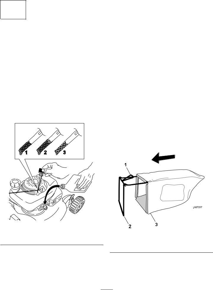
7.Read the oil level on the dipstick (Figure 6).
•If the oil level on the dipstick is too low, carefully pour a small amount of oil into the oil-fill tube, wait 3 minutes, and repeat steps 5 through 7 until the oil on the dipstick is at the correct level.
•If the oil level on the dipstick is too high, drain the excess oil until the oil on the dipstick is at the correct level; refer to Changing the Engine Oil (page 15).
Important: If the oil level in the engine is too low or too high and you run the engine, you may damage the engine.
8.Install the dipstick into the oil-fill tube securely.
Engine oil capacity |
0.55 L (18.6 fl oz) |
|
|
|
4 |
||
Oil viscosity |
SAE 30 or SAE 10W-30 |
|
|
|
detergent oil |
|
|
API service classification |
SJ or higher |
|
1.Move the machine to a level surface.
2.Remove the dipstick by rotating the cap counterclockwise and pulling it out (Figure 6).
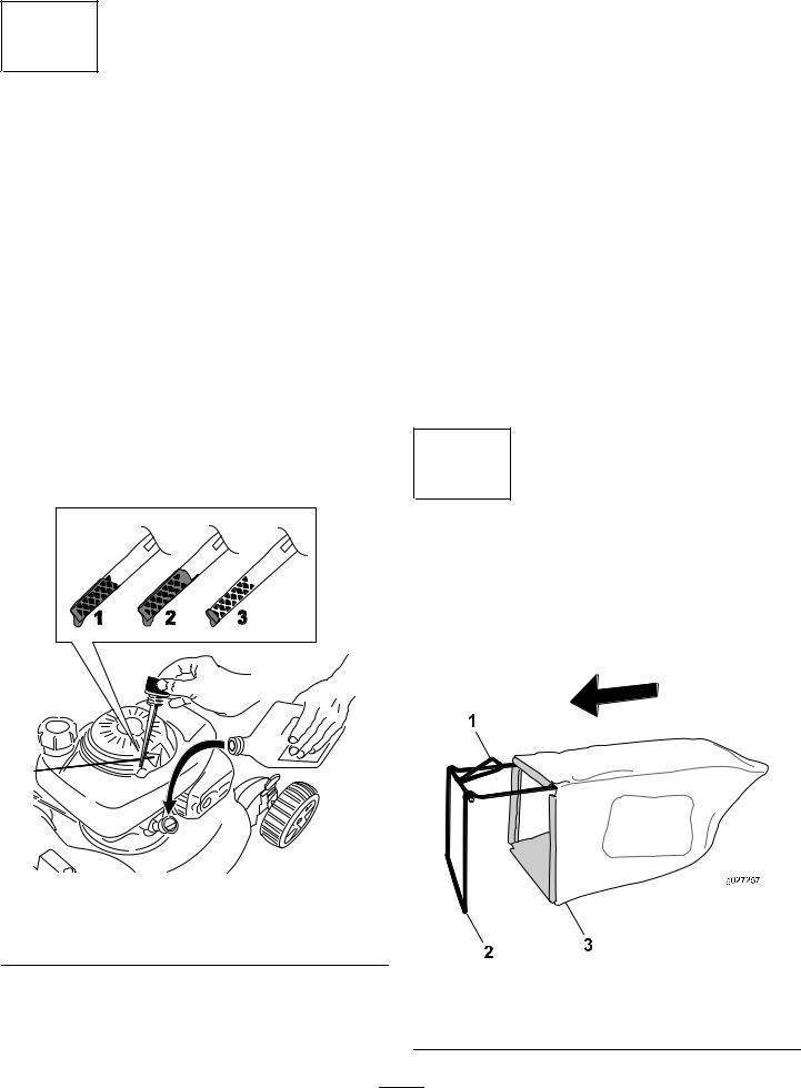
Assembling the Grass Bag
No Parts Required
Procedure
1.Slip the grass bag over the frame as shown in Figure 7.
g238622
Figure 6
1. Full |
3. Low |
2.High
3.Carefully pour about 3/4 of the engine capacity
of oil into the oil-fill tube.
4.Wait 3 minutes for the oil to settle in the engine.
5.Wipe the dipstick clean with a clean cloth.
6.Insert the dipstick into the oil-fill tube, but do not screw it in, then remove the dipstick.
g027257
Figure 7
1. Handle |
3. Grass bag |
2.Frame
Note: Do not slip the bag over the handle (Figure 7).
2.Hook the bottom channel of the bag onto the bottom of the frame (Figure 8).
5

Product Overview
g027258
Figure 8
3.Hook the top and side channels of the bag onto the top and sides of the frame, respectively (Figure 8).
g014379
Figure 9
1. |
Bag-on-demand lever |
7. |
Blade-control bar |
2. |
Cutting-height lever (2) |
8. |
Traction-assist handle |
3. |
Oil-fill tube/dipstick |
9. |
Rear-deflector door |
4. |
Grass bag |
10. |
Fuel-tank cap |
5. |
Recoil-start handle |
11. |
Air filter |
6. |
Upper handle |
12. |
Spark plug |
|
|
|
|
Specifications
Model |
Weight |
Length |
Width |
Height |
|
|
|
|
|
20837 |
38 kg |
152 cm |
53 cm |
109 cm |
|
(84 lb) |
(60 |
(21 |
(43 |
|
|
inches) |
inches) |
inches) |
6

Operation
Note: Determine the left and right sides of the machine from the normal operating position.
Before Operation
Before Operation Safety
General Safety
•Become familiar with the safe operation of the equipment, operator controls, and safety signs.
•Check that all guards and safety devices, such as deflectors and/or grass catcher, are in place and working properly.
•Always inspect the machine to ensure that the blades, blade bolts, and cutting assembly are not worn or damaged.
•Inspect the area where you will use the machine, and remove all objects that could interfere with the operation of the machine or that the machine could throw.
•Adjusting the cutting height may bring you into contact with the moving blade, causing serious injury.
–Shut off the engine, remove the ignition key (electric-start model only), and wait for all moving parts to stop.
–Do not put your fingers under the housing when adjusting the cutting height.
Fuel Safety
•Fuel is extremely flammable and highly explosive. A fire or explosion from fuel can burn you and others and can damage property.
–To prevent a static charge from igniting the fuel, place the container and/or machine directly on the ground before filling, not in a vehicle or on an object.
–Fill the fuel tank outdoors, in an open area, when the engine is cold. Wipe up any fuel that spills.
–Do not handle fuel when smoking or around an open flame or sparks.
–Do not remove the fuel cap or add fuel to the tank while the engine is running or hot.
–If you spill fuel, do not attempt to start the engine. Avoid creating a source of ignition until the fuel vapors have dissipated.
–Store fuel in an approved container and keep it out of the reach of children.
•Fuel is harmful or fatal if swallowed. Long-term exposure to vapors can cause serious injury and illness.
–Avoid prolonged breathing of vapors.
–Keep your hands and face away from the nozzle and the fuel-tank opening.
–Keep fuel away from your eyes and skin.
Filling the Fuel Tank
•For best results, use only clean, fresh, unleaded gasoline with an octane rating of 87 or higher ((R+M)/2 rating method).
•Oxygenated fuel with up to 10% ethanol or 15% MTBE by volume is acceptable.
•Do not use ethanol blends of gasoline, such as E15 or E85, with more than 10% ethanol by volume. Performance problems and/or engine damage may result, which may not be covered under warranty.
•Do not use gasoline containing methanol.
•Do not store fuel either in the fuel tank or in fuel containers over the winter unless fuel stabilizer has been added to the fuel.
•Do not add oil to gasoline.
Fill the fuel tank with fresh unleaded regular gasoline from a major name-brand service station (Figure 10).
Important: To reduce starting problems, add fuel stabilizer to the gasoline all season. Mix the stabilizer with gasoline less than 30 days old.
g230458
Figure 10
7

Checking the Engine-Oil
Level
Service Interval: Before each use or daily
1.Move the machine to a level surface.
2.Remove the dipstick by rotating the cap counterclockwise and pulling it out (Figure 11).
Adjusting the Handle
Height
You may raise or lower the handle to a position comfortable for you.
Rotate the handle lock, move the handle to 1 of 3 positions, and lock the handle into position (Figure 12).
g238622
Figure 11
1. |
Full |
3. Low |
g007284 |
||
Figure 12 |
|||||
2. |
High |
|
|
||
|
1. Handle lock |
2. Handle positions |
|||
|
|
|
|||
3.Wipe the dipstick clean with a clean cloth.
4.Insert the dipstick into the oil-fill tube, but do not screw it in, then remove the dipstick.
5.Read the oil level on the dipstick (Figure 11).
•If the oil level on the dipstick is too low (Figure 11), carefully pour a small amount of SAE 30 or SAE 10W-30 detergent oil into the oil-fill tube, wait 3 minutes, and repeat steps 3 through 5 until the oil on the dipstick is at the correct level.
•If the oil level on the dipstick is too high (Figure 11), drain the excess oil until the oil on the dipstick is at the correct level; refer to Changing the Engine Oil (page 15).
Important: If the oil level in the engine is too low or too high and you run the engine, you may damage the engine.
6.Install the dipstick into the oil-fill tube securely.
8

Adjusting the Cutting
Height
Adjust the cutting height as desired. Set all the cutting-height levers to the same height. To raise and lower the machine, refer to Figure 13.
g012130
Figure 13
1.Cutting-height lever
Important: The cutting height settings are 25 mm (1 inch); 38 mm (1-1/2 inch); 51 mm (2 inches); 64 mm (2-1/2 inches); 83 mm (3-1/4 inches); 95 mm (3-3/4 inches); 108 mm (4-1/4 inches).
During Operation
During Operation Safety
General Safety
•Wear appropriate clothing, including eye protection; long pants; slip-resistant, substantial footwear; and hearing protection. Tie back long hair, secure loose clothing, and do not wear loose jewelry.
•Do not operate the machine while ill, tired, or under the influence of alcohol or drugs.
•The blade is sharp; contacting the blade can result in serious personal injury. Shut off the engine, remove the ignition key (electric-start model only), and wait for all moving parts to stop before leaving the operating position.
•When you release the blade-control bar, the engine should shut off and the blade should stop within 3 seconds. If not, stop using your machine immediately and contact an Authorized Service Dealer.
•Keep bystanders, especially small children, out of the operating area. Stop the machine if anyone enters the area.
•Always look down and behind you before moving the machine in reverse.
•Operate the machine only in good visibility and appropriate weather conditions. Do not operate the machine when there is the risk of lighting.
•Wet grass or leaves can cause serious injury if you slip and contact the blade. Avoid mowing in wet conditions.
•Use extreme care when approaching blind corners, shrubs, trees, or other objects that may block your view.
•Watch for holes, ruts, bumps, rocks, or other hidden objects. Uneven terrain could cause the machine to overturn or cause you to lose your balance or footing.
•Stop the machine, shut off the engine, wait for all moving parts to stop, and inspect the blades after striking an object or if there is an abnormal vibration in the machine. Make all necessary repairs before resuming operation.
•Before leaving the operating position, shut off the engine, remove the ignition key (electric-start model only), and wait for all moving parts to stop.
•If the engine has been running the muffler will be hot and can severely burn you. Keep away from the hot muffler.
•Check the grass catcher components and the discharge chute frequently for any wear
9
or deterioration and replace them with the manufacturer's recommended parts when necessary.
•Use accessories and attachments approved by The Toro® Company only.
Slope Safety
•Mow across the face of slopes; never up and down. Use extreme caution when changing direction on slopes.
•Do not mow on excessively steep slopes. Poor footing could cause a slip-and-fall accident.
•Mow with caution near drop-offs, ditches, or embankments.
Using the Self-Propel Drive
To operate the self-propel drive, simply walk with your hands on the upper handle and your elbows at your sides, and the machine will automatically keep pace with you (Figure 14).
g003221
Figure 14
Note: If the machine does not freely roll backward after self-propelling, stop walking, hold your hands in place, and allow the machine to roll a couple of centimeters (inches) forward to disengage the wheel drive. You can also try reaching just under the upper handle to the metal handle and pushing the machine forward a couple of centimeters (inches). If the machine still does not roll backward easily, contact an Authorized Service Dealer.
Shutting Off the Engine
Service Interval: Before each use or daily
To shut off the engine, release the blade-control bar.
Important: When you release the blade-control bar, the engine should shut off and the blade should stop within 3 seconds. If they do not, stop using your machine immediately and contact an Authorized Service Dealer.
Recycling the Clippings
Your machine comes from the factory ready to recycle the grass and leaf clippings back into the lawn.
Note: The grass bag may remain on the machine while you are recycling the clippings.
To recycle the clippings, move the bag-on-demand lever to the RECYCLING position (Figure 15).
g012135
Figure 15
1. RECYCLING position |
2. BAGGING position |
|
|
10

Bagging the Clippings
Use the grass bag to collect grass and leaf clippings from the lawn.

 WARNING
A worn grass bag could allow small stones and other similar debris to be thrown toward you or bystanders, resulting in serious personal injury or death.
Check the grass bag frequently. If it is damaged, install a new Toro replacement bag.

 WARNING
The blade is sharp; contacting the blade can result in serious personal injury.
Shut off the engine and wait for all moving parts to stop before leaving the operating position.
1.Shut off the engine and wait for all moving parts to stop.
2.Install the grass bag; refer to Installing the Grass Bag (page 11) and move the bag-on-demand lever to the BAGGING position as shown in Figure 15.
Installing the Grass Bag
1.Shut off the engine and wait for all moving parts to stop.
2.Raise and hold up the rear deflector, install the bag in the notches, and lower the rear deflector (Figure 16).
g014468
Figure 16
Removing the Grass Bag
1.Shut off the engine and wait for all moving parts to stop.
2.Lift up the grass bag up and away from the handle.
Note: Tilt the grass bag slightly backward to prevent the collected grass clippings from falling out.
Rear-Discharging the
Clippings
Use the rear discharge for cutting very tall grass.
Note: If the grass bag is on the machine, remove it before rear-discharging the clippings; refer
to Removing the Grass Bag (page 11). The bag-on-demand lever should be in the BAGGING position as shown in Figure 15.

 WARNING
The blade is sharp; contacting the blade can result in serious personal injury.
Shut off the engine and wait for all moving parts to stop before leaving the operating position.
11

Operating Tips
General Mowing Tips
•Inspect the area where you will use the machine and remove all objects that the machine could throw.
•Avoid striking solid objects with the blade. Never deliberately mow over any object.
•If the machine strikes an object or starts to vibrate, immediately shut off the engine, remove the key (if equipped), disconnect the wire from the spark plug, and examine the machine for damage.
•For best performance, install a new blade before the cutting season begins.
•Replace the blade when necessary with a Toro replacement blade.
Cutting Grass
•Cut only about a third of the grass blade at a time. Do not cut below 51 mm (2 inches) unless the grass is sparse or it is late fall when grass growth begins to slow down.
•When cutting grass over 15 cm (6 inches) tall, mow at the highest cutting height setting and walk slower; then mow again at a lower setting for the best lawn appearance. If the grass is too long, the machine may plug and cause the engine to stall.
•Wet grass and leaves tend to clump on the yard and can cause the machine to plug or the engine to stall. Avoid mowing in wet conditions.
•Be aware of a potential fire hazard in very dry conditions, follow all local fire warnings, and keep the machine free of dry grass and leaf debris.
•Alternate the mowing direction. This helps disperse the clippings over the lawn for even fertilization.
•If the finished lawn appearance is unsatisfactory, try 1 or more of the following:
–Replace the blade or have it sharpened.
–Walk at a slower pace while mowing.
–Raise the cutting height on your machine.
–Cut the grass more frequently.
–Overlap cutting swaths instead of cutting a full swath with each pass.
Cutting Leaves
•After cutting the lawn, ensure that half of the lawn shows through the cut leaf cover. You may need to make more than a single pass over the leaves.
•If there are more than 13 cm (5 inches) of leaves on the lawn, mow at a higher cutting height and then again at the desired cutting height.
•Slow down your mowing speed if the machine does not cut the leaves finely enough.
12

After Operation
After Operation Safety
General Safety
•Clean grass and debris from the machine to help prevent fires. Clean up oil or fuel spills.
•Allow the engine to cool before storing the machine in any enclosure.
•Never store the machine or fuel container where there is an open flame, spark, or pilot light, such as on a water heater or on other appliances.
Hauling Safety
•Remove the ignition key (if equipped) before loading the machine for hauling.
•Use care when loading or unloading the machine.
•Secure the machine from rolling.
Cleaning under the Machine
Service Interval: Before each use or daily
For best results, clean the machine soon after you have completed mowing.
1.Lower the machine to the lowest cutting-height setting. Refer to Adjusting the Cutting Height (page 9).
2.Move the machine onto a level surface.
3.Attach a garden hose that is connected to a water supply to the washout port (Figure 17).
g014538
Figure 17
1.Washout port
4.Turn the water on.
5.Start the engine and run it until there are no more clippings that come out from under the machine.
6.Shut off the engine.
7.Shut off the water and disconnect the garden hose from the machine.
8.Start the engine and run it for a few minutes to dry the underside of the machine.
9.Shut off the engine and allow it to cool.
Folding the Handle

 WARNING
Folding or unfolding the handle improperly can damage the cables, causing an unsafe operating condition.
•Do not damage the cables when folding or unfolding the handle.
•If a cable is damaged, contact an Authorized Service Dealer.
1.Loosen the handle knobs.
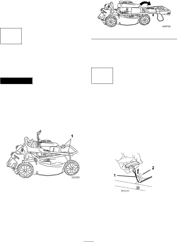
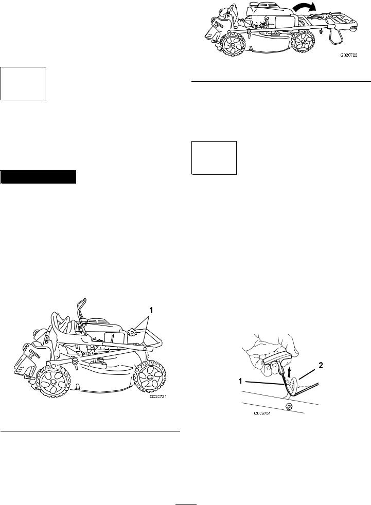
2.Rotate the entire handle forward (Figure 18).
Important: Route the cables to the outside of the handle knobs as you fold the upper handle.
g020722
Figure 18
3.Rotate the upper portion of the handle back toward the engine; refer to Figure 19.
g020721
Figure 19
1.Handle knobs
13

Maintenance
Recommended Maintenance Schedule(s)
Maintenance Service |
Maintenance Procedure |
||
Interval |
|||
|
|
||
|
|
|
|
After the first 5 hours |
• |
Change the engine oil. |
|
|
|
|
|
|
• |
Check the engine-oil level. |
|
Before each use or daily |
• |
Ensure that the engine shuts off within 3 seconds after releasing the blade-control |
|
|
bar. |
||
|
|
||
|
• |
Clean grass clippings and dirt from under the machine. |
|
|
|
|
|
Every 100 hours |
• |
Service the spark plug. |
|
|
|
|
|
|
• |
Service the air filter. |
|
|
• |
Change the engine oil. |
|
Yearly |
• |
Replace the blade or have it sharpened (more frequently if the edge dulls quickly). |
|
|
• |
Clean the engine by removing dirt and debris from its top and sides; clean it more |
|
|
|
frequently in dusty operating conditions. |
|
Yearly or before storage |
• |
Empty the fuel tank before repairs as directed and before yearly storage. |
|
|
|
|
|
Important: Refer to your engine owner’s manual for additional maintenance procedures.
Maintenance Safety
•Disconnect the spark-plug wire from the spark plug before performing any maintenance procedure.
•Wear gloves and eye protection when servicing the machine.
•The blade is sharp; contacting the blade can result in serious personal injury. Wear gloves when servicing the blade. Do not repair or alter the blade(s).
•Never tamper with safety devices. Check their proper operation regularly.
•Tipping the machine may cause the fuel to leak. Fuel is flammable and explosive, and can cause personal injury. Run the engine dry or remove the fuel with a hand pump; never siphon the fuel.
•To ensure optimum performance and continued safety certification of the machine, use only genuine Toro replacement parts and accessories. Replacement parts and accessories made by other manufacturers could be dangerous, and such use could void the product warranty.
Preparing for Maintenance
1.Shut off the engine and wait for all moving parts to stop.
2.Disconnect the spark-plug wire from the spark plug (Figure 20).
g238653
Figure 20
1.Spark-plug wire
3.After performing the maintenance procedure(s), connect the spark-plug wire to the spark plug.
Important: Before tipping the machine to change the oil or replace the blade, allow the fuel tank to run dry through normal usage. If you must tip the machine prior to running out of fuel, use a hand fuel pump to remove the fuel. Always tip the machine onto its side, with the dipstick down.
14

Servicing the Air Filter
Service Interval: Yearly
1.Press down on the latch tabs on top of the air-filter cover (Figure 21).
Changing the Engine Oil
Service Interval: After the first 5 hours
Yearly
Note: Run the engine a few minutes before changing the oil to warm it. Warm oil flows better and carries more contaminants.
Engine Oil Specifications
Engine oil capacity |
0.55 L (18.6 fl oz) |
|
|
Oil viscosity |
SAE 30 or SAE 10W-30 |
|
detergent oil |
API service classification |
SJ or higher |
|
|
1.Move the machine to a level surface.
2.Refer to Preparing for Maintenance (page 14).
3.Remove the dipstick by rotating the cap counterclockwise and pulling it out (Figure 22).
g011722
Figure 21
1. Latch tabs |
3. Foam pre-filter |
g010272 |
2. |
Paper air filter |
|
Figure 22 |
|
|
||
|
|
|
|
|
|
|
4. Tip the machine onto its side (so that the air |
2. |
Open the cover. |
|
|
3. |
Remove the paper air filter and the foam |
|
filter is up) to drain the used oil from the oil-fill |
|
tube (Figure 22). |
||
|
pre-filter (Figure 21). |
|
|
|
|
|
4.Inspect the foam pre-filter, and replace it if it is damaged or excessively dirty.
5.Inspect the paper air filter.
•If the air filter is damaged or is wet with oil or fuel, replace it.
•If the air filter is dirty, tap it on a hard surface several times or blow compressed air less than 207 kPa (30 psi) through the side of the filter that faces the engine.
Note: Do not brush the dirt off the filter; brushing forces dirt into the fibers.
6.Remove the dirt from the air-filter body and the cover using a moist rag.
Important: Do not wipe dirt into the air duct.
7.Install the foam pre-filter and the paper air filter into the air filter.
8.Install the cover.
15

Servicing the Spark Plug
Service Interval: Every 100 hours
Use a Champion RN9YC spark plug or equivalent.
1. Shut off the engine and wait for all moving parts to stop.
2. Disconnect the wire from the spark plug (Figure 20).
3. Clean around the spark plug.
4. Remove the spark plug from the cylinder head.
Important: Replace a cracked, fouled, or dirty spark plug. Do not clean the electrodes because grit entering the cylinder can damage the engine.
5. Set the gap on the plug to 0.76 mm (0.030 inch) as shown in Figure 24.
g238622
|
|
Figure 23 |
1. |
Full |
3. Low |
2. |
High |
|
5.After draining the used oil, return the machine to the operating position.
6.Carefully pour about 3/4 of the engine capacity of oil into the oil-fill tube.
7.Wait 3 minutes for the oil to settle in the engine.
8.Wipe the dipstick clean with a clean cloth.
9.Insert the dipstick into the oil-fill tube, but do not screw it in, then remove the dipstick.
10.Read the oil level on the dipstick ( Checking the Engine-Oil Level (page 8)).
•If the oil level on the dipstick is too low, carefully pour a small amount of oil into the oil-fill tube, wait 3 minutes, and repeat steps 8 through 10 until the oil level on the dipstick is correct.
•If the oil level on the dipstick is too high, drain the excess oil until the oil level on the dipstick is correct.
Important: If the oil level in the engine is too low or too high and you run the engine, you may damage the engine.
11.Install the dipstick into the oil-fill tube securely.
12.Recycle the used oil properly.
g000533
Figure 24
1. Center electrode insulator 3. Air gap (not to scale)
2.Side electrode
6.Install the spark plug.
7.Torque the plug to 20 N∙m (15 ft-lb).
8.Connect the wire to the spark plug.
16

Replacing the Blade
Service Interval: Yearly
Important: You will need a torque wrench to install the blade properly. If you do not have a torque wrench or are uncomfortable performing this procedure, contact an Authorized Service Dealer.
Examine the blade whenever you run out of fuel. If the blade is damaged or cracked, replace it immediately. If the blade edge is dull or nicked, have it sharpened and balanced, or replace it.

 WARNING
The blade is sharp; contacting the blade can result in serious personal injury.
Wear gloves when servicing the blade.
1.Refer to Preparing for Maintenance (page 14).
2.Tip the machine onto its side with the air filter up.
3.Use a block of wood to hold the blade steady (Figure 25).
g231390
Figure 26
Important: Position the curved ends of the blade to point toward the machine housing.
6.Use a torque wrench to tighten the blade bolt to 82 N∙m (60 ft-lb).
Important: A bolt torqued to 82 N∙m (60 ft-lb) is very tight. While holding the blade with a block of wood, put your weight behind the ratchet or wrench and tighten the bolt securely. This bolt is very difficult to overtighten.
g231389
Figure 25
4.Remove the blade, saving all mounting hardware (Figure 25).
5.Install the new blade and all mounting hardware (Figure 26).
17

Storage
Store the machine in a cool, clean, dry place.
Preparing the Machine for Storage
1.On the last refueling of the year, add fuel stabilizer (such as Toro Premium Fuel Treatment) to the fuel as directed on the label.
2.Dispose of any unused fuel properly. Recycle it according to local codes or use it in your automobile.
Note: Old fuel in the fuel tank is the leading cause of hard starting. Do not store fuel without fuel stabilizer more than 30 days, and do not store stabilized fuel more than 90 days.
3.Run the machine until the engine shuts off from running out of fuel.
4.Start the engine again and allow it to run until it shuts off. When you can no longer start the engine, it is sufficiently dry.
5.Disconnect the wire from the spark plug and connect the wire to the retaining post (if equipped).
6.Remove the spark plug, add 30 ml (1 fl oz) of engine oil through the spark-plug hole, and pull the starter rope slowly several times to distribute oil throughout the cylinder to prevent cylinder corrosion during the off-season.
7.Loosely install the spark plug.
8.Tighten all nuts, bolts, and screws.
Removing the Machine from Storage
1.Check and tighten all fasteners.
2.Remove the spark plug and spin the engine rapidly by pulling the recoil-start handle to blow the excess oil from the cylinder.
3.Install the spark plug and tighten it with a torque wrench to 20 N∙m (15 ft-lb).
4.Perform any maintenance procedures; refer to Maintenance (page 14).
5.Check the engine-oil level; refer to Checking the Engine-Oil Level (page 8).
6.Fill the fuel tank with fresh fuel; refer to Filling the Fuel Tank (page 7).
7.Connect the wire to the spark plug.
18

Notes:
European Privacy Notice
The Information Toro Collects
Toro Warranty Company (Toro) respects your privacy. In order to process your warranty claim and contact you in the event of a product recall, we ask you to share certain personal information with us, either directly or through your local Toro company or dealer.
The Toro warranty system is hosted on servers located within the United States where privacy law may not provide the same protection as applies in your country.
BY SHARING YOUR PERSONAL INFORMATION WITH US, YOU ARE CONSENTING TO THE PROCESSING OF YOUR PERSONAL INFORMATION AS DESCRIBED IN THIS PRIVACY NOTICE.
The Way Toro Uses Information
Toro may use your personal information to process warranty claims, to contact you in the event of a product recall and for any other purpose which we tell you about. Toro may share your information with Toro's affiliates, dealers or other business partners in connection with any of these activities. We will not sell your personal information to any other company. We reserve the right to disclose personal information in order to comply with applicable laws and with requests by the appropriate authorities, to operate our systems properly or for our own protection or that of other users.
Retention of your Personal Information
We will keep your personal information as long as we need it for the purposes for which it was originally collected or for other legitimate purposes (such as regulatory compliance), or as required by applicable law.
Toro's Commitment to Security of Your Personal Information
We take reasonable precautions in order to protect the security of your personal information. We also take steps to maintain the accuracy and current status of personal information.
Access and Correction of your Personal Information
If you would like to review or correct your personal information, please contact us by email at legal@toro.com.
Australian Consumer Law
Australian customers will find details relating to the Australian Consumer Law either inside the box or at your local Toro Dealer.
374-0282 Rev C

Form No. 3419-115 Rev A
48 cm Super Recycler® Rasenmäher
Modellnr. 20837—Seriennr. 401500000 und höher
Bedienungsanleitung
Einführung
Dieser handgeführte Rasenmäher mit Sichelmessern sollte von Privatleuten oder geschulten Lohnarbeitern verwendet werden. Er ist hauptsächlich für das Mähen von Gras auf gepflegten Grünflächen in Privatanlagen gedacht. Er ist nicht für das Schneiden von Büschen oder für einen landwirtschaftlichen Einsatz gedacht.
Lesen Sie diese Informationen sorgfältig durch, um sich mit dem ordnungsgemäßen Einsatz und der Wartung des Geräts vertraut zu machen und Verletzungen und eine Beschädigung des Geräts zu vermeiden. Sie tragen die Verantwortung für einen
ordnungsgemäßen und sicheren Einsatz des Geräts.
In dieser Anleitung werden potenzielle Gefahren angeführt, und Sicherheitsmeldungen werden vom Sicherheitswarnsymbol (Bild 2) gekennzeichnet, das auf eine Gefahr hinweist, die zu schweren oder tödlichen Verletzungen führen kann, wenn Sie die empfohlenen Sicherheitsvorkehrungen nicht einhalten.
g000502
Bild 2
Sicherheitswarnsymbol
Wenden Sie sich hinsichtlich Informationen zu Produkten und Zubehör sowie Angaben zu Ihrem örtlichen Vertragshändler oder zur Registrierung des Produktes direkt an Toro unter www.Toro.com.
Wenden Sie sich an den Toro-Vertragshändler oder Kundendienst, wenn Sie eine Serviceleistung, Originalersatzteile von Toro oder weitere
Informationen benötigen. Haben Sie dafür die Modellund Seriennummern der Maschine griffbereit. In Bild 1 wird der Standort der Modellund Seriennummern auf dem Produkt angegeben. Tragen Sie hier bitte die Modellund Seriennummern des Geräts ein.
Wichtig: Scannen Sie mit Ihrem Mobilgerät den QR-Code auf dem Seriennummernaufkleber (falls vorhanden), um auf Garantie-, Ersatzteiloder andere Produktinformationen zuzugreifen.
In dieser Anleitung werden zwei Begriffe zur Hervorhebung von Informationen verwendet. Wichtig weist auf spezielle mechanische Informationen hin, und Hinweis hebt allgemeine Informationen hervor, die Ihre besondere Beachtung verdienen.
Dieses Produkt erfüllt alle relevanten europäischen Richtlinien; weitere Details finden Sie in der produktspezifischen Konformitätserklärung (DOC).
Bruttooder Nettodrehmoment: Das Bruttooder Nettodrehmoment dieses Motors wurde vom Motorhersteller im Labor gemäß SAE J1940 oder J2723 ermittelt. Aufgrund der Konfiguration zur Erfüllung von Sicherheits-, Emissions-
und Betriebsanforderungen ist die tatsächliche Motorleistung in dieser Klasse der Rasenmäher wesentlich niedriger. Weitere Informationen finden Sie in der Motorbedienungsanleitung des Herstellers, die mit der Maschine ausgeliefert wurde.
Inhalt
|
g226629 |
|
|
|
|
Einführung ................................................................ |
1 |
Bild 1 |
|
|
|
|
|
Sicherheit .................................................................. |
2 |
1. Typenschild mit Modellund Seriennummer |
|
Allgemeine Sicherheit......................................... |
2 |
|
|
Sicherheitsund Bedienungsschilder ................. |
3 |
|
|
Einrichtung ................................................................ |
4 |
|
|
1 Aufklappen des Holms..................................... |
4 |
Modellnr. |
|
2 Befestigen des Rücklaufstarterseils in der |
|
|
|
Seilführung...................................................... |
4 |
Seriennr. |
|
3 Auffüllen des Motors mit Öl .............................. |
4 |
|
|
4 Montieren des Fangkorbs ................................ |
5 |
|
|
Produktübersicht ....................................................... |
6 |
© 2017—The Toro® Company 8111 Lyndale Avenue South Bloomington, MN 55420
CV
Registrieren Sie Ihr Produkt unter |
Originaldokuments (DE) |
*3419-115* A |
www.Toro.com. |
Druck: Tschechische Republik |
|
|
Alle Rechte vorbehalten |

Technische Daten .............................................. |
6 |
Betrieb ...................................................................... |
7 |
Vor dem Einsatz .................................................... |
7 |
Vor der sicheren Verwendung............................. |
7 |
Betanken ............................................................ |
8 |
Prüfen des Motorölstands................................... |
8 |
Einstellen der Holmhöhe..................................... |
9 |
Einstellen der Schnitthöhe.................................. |
9 |
Während des Einsatzes ....................................... |
10 |
Hinweise zur Sicherheit während des |
|
Betriebs......................................................... |
10 |
Verwenden des Selbstantriebs .......................... |
11 |
Abstellen des Motors ......................................... |
11 |
Schnittgutrecyclen............................................. |
11 |
Sammeln des Schnittguts................................. |
12 |
Heckauswurf des Schnittguts ........................... |
13 |
Betriebshinweise ............................................. |
13 |
Nach dem Einsatz ............................................... |
14 |
Hinweise zur Sicherheit nach dem |
|
Betrieb .......................................................... |
14 |
Reinigen unter dem Gerät................................. |
14 |
Zusammenklappen des Holms ......................... |
15 |
Wartung .................................................................. |
16 |
Empfohlener Wartungsplan ................................. |
16 |
Wartungssicherheit........................................... |
16 |
Vorbereiten für die Wartung .............................. |
16 |
Warten des Luftfilters........................................ |
17 |
Wechseln des Motoröls .................................... |
17 |
Warten der Zündkerze ...................................... |
18 |
Auswechseln des Messers ............................... |
19 |
Einlagerung ............................................................ |
20 |
Vorbereiten der Maschine für das |
|
Einlagern....................................................... |
20 |
Herausnehmen des Rasenmähers aus der |
|
Einlagerung................................................... |
20 |
Sicherheit
Diese Maschine erfüllt EN ISO 5395:2013.
Allgemeine Sicherheit
Dieses Produkt kann Hände und Füße amputieren und Gegenstände aufschleudern. Befolgen immer sämtliche Sicherheitshinweise, um schwere oder tödliche Verletzungen zu vermeiden.
Wenn dieses Produkt für einen anderen Zweck eingesetzt wird, kann das für Bediener und andere Personen gefährlich sein.
•Lesen, verstehen und befolgen Sie vor dem Anlassen des Motors alle Anweisungen und Warnungen in der Bedienungsanleitung und an der Maschine.
•Berühren Sie bewegliche Teile oder die Unterseite der Maschine nicht mit den Händen oder Füßen. Kommen Sie Auswurföffnungen nicht zu nahe.
•Setzen Sie die Maschine nur ein, wenn alle Schutzvorrichtungen und andere Sicherheitsvorrichtungen montiert und funktionsfähig sind.
•Halten Sie Unbeteiligte und Kinder in einem sicheren Abstand zur Maschine. Das Fahrzeug darf niemals von Kindern betrieben werden. Nur verantwortungsbewusste Personen, die geschult und mit den Anweisungen vertraut sind und körperlich fähig sind, sollten die Maschine verwenden.
•Halten Sie die Maschine an, stellen Sie den Motor ab und warten Sie, bis alle beweglichen Teile zum Stillstand gekommen sind, bevor Sie Wartungsarbeiten durchführen, Auftanken oder Verstopfungen entfernen.
Der unsachgemäße Einsatz oder die falsche Wartung dieser Maschine kann zu Verletzungen führen. Durch das Befolgen dieser Sicherheitshinweise kann das Verletzungsrisiko verringert werden. Achten Sie immer auf das Warnsymbol. Es bedeutet Vorsicht, Warnung oder Gefahr – Hinweise für die Personensicherheit. Wenn Sie diese Anweisungen nicht einhalten, kann es zu Verletzungen ggf. tödlichen Verletzungen kommen.
Sie finden weitere Sicherheitsinformationen bei Bedarf in dieser Bedienungsanleitung.
2
Sicherheitsund Bedienungsschilder
Die Sicherheitsund Bedienungsaufkleber sind gut sichtbar; sie befinden sich in der Nähe der möglichen Gefahrenbereiche. Tauschen Sie beschädigte oder verloren gegangene Aufkleber aus.
decaloemmarkt
Herstellermarke
1.Diese Marke gibt an, dass das Messer ein Teil des Herstellers der Originalmaschine ist.
decal112-8760
112-8760
1.Gefahr durch herausgeschleuderte Gegenstände: Achten Sie darauf, dass Unbeteiligte den Sicherheitsabstand zur Maschine einhalten.
2.Gefahr einer Schnittwunde und/oder der Amputation von Händen oder Füßen: Berühren Sie keine beweglichen Teilen.
decal119-2283
119-2283
1.Schnitthöhe Einstellungen
decal131-4514b
131-4514
1.Warnung: Lesen Sie die Bedienungsanleitung.
2.Schnittbzw. Amputationsgefahr für Hände am Mähwerkmesser: Berühren Sie keine beweglichen Teile und nehmen Sie keine Schutzbleche und Schutzvorrichtungen ab.
3.Schnittbzw. Amputationsgefahr an den Händen beim Schnittmesser: Ziehen Sie den Zündkerzenstecker ab und lesen Sie die Anweisungen, bevor Sie Wartungsoder Reparaturarbeiten ausführen.
4.Gefahr durch herausgeschleuderte Gegenstände: Stellen Sie sicher, dass Unbeteiligte immer einen
Sicherheitsabstand zur Maschine einhalten; stellen Sie den Motor ab, bevor Sie die Bedienerposition verlassen und sammeln Sie Rückstände vor dem Einsatz der Maschine auf.
5.Schnittbzw. Amputationsgefahr von Händen am Mähwerkmesser: Mähen Sie nie hangaufwärts oder -abwärts, mähen Sie immer waagrecht zum Hang. Schauen Sie nach hinten, wenn Sie rückwärtsfahren.
decal137-9196
137-9196
1. Einrasten |
2. Ausrasten |
|
|
3
Einrichtung
Wichtig: Nehmen Sie den Kunststoffschutz ab und alle anderen Kunststoffteile oder
Verpackungen ab, mit denen der Motor abgedeckt ist. Werfen Sie sie ab.
1
Aufklappen des Holms
Keine Teile werden benötigt
g020722
Bild 4
3.Ziehen Sie die Griffhandräder mit der Hand fest.
4.Drehen Sie den Bügel nach hinten in die Betriebsstellung und arretieren Sie ihn in der gewünschten Höhe. Siehe Einstellen der Holmhöhe (Seite 9).
Verfahren

 WARNUNG:
Wenn Sie den Holm falsch aufoder zusammenklappen, können Sie die Bowdenzüge beschädigen und den sicheren Geräteeinsatz gefährden.
•Beschädigen Sie beim Aufoder Zusammenklappen des Holms nicht die Kabel.
•Wenden Sie sich bei einem beschädigten Kabel an einen offiziellen Vertragshändler.
1.Lösen Sie die Griffhandräder (Bild 3).
g020721
Bild 3
1.Griffhandräder
2.Schieben Sie den oberen Griff vorsichtig nach
vorne, bis die Griffhälften ausgerichtet sind und eng anliegen, siehe Bild 4.
2
Befestigen des Rücklaufstarterseils in der Seilführung
Keine Teile werden benötigt
Verfahren
Wichtig: Befestigen Sie das Rücklaufstarterseil in der Seilführung, um den Motor sicher und mühelos anzulassen.
Drücken Sie den Schaltbügel zum oberen Holm und ziehen Sie das Rücklaufstarterseil durch die Seilführung am Holm (Bild 5).
g003251
Bild 5
1. Rücklaufstarterseil |
2. Seilführung |
|
|
4
3
Auffüllen des Motors mit Öl
Keine Teile werden benötigt
Verfahren
Wichtig: Die Maschine hat bei der Auslieferung kein Öl im Motor. Füllen Sie den Motor mit Öl, bevor Sie ihn anlassen.
Motorölsorte
Motorölmenge |
0,55 l |
Ölviskosität |
Waschaktives Öl der Sorte |
|
SAE 30 oder SAE 10W-30 |
API-Klassifikation |
SJ oder höher |
1.Stellen Sie die Maschine auf einer ebenen Fläche ab.
2.Entfernen Sie den Peilstab, indem Sie den Deckel nach links drehen und herausziehen (Bild 6).
g238622
Bild 6
1. Voll |
3. Niedrig |
2.Hoch
3.Gießen Sie ca. ¾ der Motorölfüllmenge langsam
in den Öleinfüllstutzen.
4.Warten Sie drei Minuten, damit sich das Öl im Motor setzen kann.
5.Wischen Sie den Peilstab mit einem sauberen Lappen ab.
6.Stecken Sie den Peilstab in den Öleinfüllstutzen, schrauben Sie ihn jedoch nicht ein; nehmen Sie den Peilstab dann heraus.
7.Lesen Sie den Ölstand am Peilstab ab. (Bild 6)
•Wenn der Ölstand am Peilstab zu niedrig ist, füllen Sie langsam etwas Öl in den Öleinfüllstutzen, warten Sie drei Minuten und wiederholen Sie dann die Schritte 5 bis 7, bis der Ölstand am Peilstab richtig ist.
•Wenn der Ölstand am Peilstab zu hoch ist, lassen Sie Öl ab, bis der Ölstand am Peilstab richtig ist, siehe Wechseln des Motoröls (Seite 17).
Wichtig: Wenn der Ölstand im Motor zu hoch oder zu niedrig ist und Sie den
Motor laufen lassen, können Motorschäden auftreten.
8.Stecken Sie den Peilstab fest in den Öleinfüllstutzen.
4
Montieren des Fangkorbs
Keine Teile werden benötigt
Verfahren
1.Schieben Sie den Fangkorb auf den Rahmen, wie in Bild 7 abgebildet.
g027257
Bild 7
1. Holm |
3. Fangkorb |
2.Rahmen
5
Loading...