


 Loading...
Form No. 3406-741 Rev A
Power Max® 724 OE Snowthrower
Power Max® 826 OE Snowthrower
Model No. 37779—Serial No. 400010798 and Up
Model No. 37780—Serial No. 400010798 and Up
Operator's Manual
Introduction
 WARNING
CALIFORNIA
Proposition 65 Warning
This product contains a chemical or chemicals known to the State of California to cause cancer, birth defects, or reproductive harm.
The engine exhaust from this product contains chemicals known to the State of California to cause cancer, birth defects, or other reproductive harm.
This machine is intended to be used by residential homeowners or professional, hired operators. It is designed for removing snow from paved surfaces, such as driveways and sidewalks, and other surfaces for traffic on residential or commercial properties. It is not designed for removing materials other than snow, nor is a model with a pivoting scraper designed for clearing off gravel surfaces.
Read this information carefully to learn how to operate and maintain your machine properly and to avoid injury and machine damage. You are responsible for operating the machine properly and safely.
You may contact Toro directly at www.Toro.com for machine and accessory information, help finding a dealer, or to register your machine.
Whenever you need service, genuine Toro parts, or additional information, contact an Authorized Service Dealer or Toro Customer Service and have the model and serial numbers of your machine ready. Figure 1 identifies the location of the model and serial numbers on the machine. Write the numbers in the space provided.
© 2016—The Toro® Company |
Register at www.Toro.com. |
8111 Lyndale Avenue South |
|
Bloomington, MN 55420 |
|
Figure 1
1.Model and serial number location
Model No.
Serial No.
This manual identifies potential hazards and has safety messages identified by the safety-alert symbol (Figure 2), which signals a hazard that may cause serious injury or death if you do not follow the recommended precautions.
Figure 2
1.Safety-alert symbol
This manual uses 2 words to highlight information. Important calls attention to special mechanical information and Note emphasizes general information worthy of special attention.
Important: If you are using this machine above 1500 m (5,000 ft) for a continuous period, ensure that the High Altitude Kit has been installed so that the engine meets CARB/EPA emission regulations. The High Altitude Kit increases engine performance while preventing spark-plug fouling, hard starting, and increased emissions. Once you have installed the kit, attach
the high-altitude label next to the serial decal on the machine. Contact any Authorized Toro Service Dealer
Original Instructions (EN) *3406-741* A
Printed in the USA
All Rights Reserved

to obtain the proper High Altitude Kit and high-altitude label for your machine. To locate a dealer convenient to you, access our website at www.Toro.com or contact our Toro Customer Care Department at the number(s) listed in your Emission Control Warranty Statement.
Remove the kit from the engine and restore the engine to its original factory configuration when running the engine under 1500 m (5,000 ft). Do not operate an engine that has been converted for high-altitude use at lower altitudes; otherwise, you could overheat and damage the engine.
If you are unsure whether or not your machine has been converted for high-altitude use, look for the following label (Figure 3).
Figure 3
This spark ignition system complies with Canadian ICES-002.
Contents |
|
Introduction .................................................................. |
1 |
Safety ........................................................................... |
2 |
Safety and Instructional Decals ................................. |
3 |
Setup ............................................................................ |
5 |
1 Installing the Upper Handle.................................... |
5 |
2 Installing the Traction-Control Linkage.................... |
6 |
3 Installing the Chute............................................... |
7 |
4 Installing the Chute-Control Rod ............................ |
7 |
5 Checking the Engine-Oil Level ............................... |
8 |
6 Checking the Tire Pressure..................................... |
8 |
7 Checking the Skids and Scraper............................... |
8 |
8 Checking the Operation of the Traction |
|
Drive ................................................................. |
8 |
Product Overview ......................................................... |
10 |
Operation .................................................................... |
10 |
Before Operation ...................................................... |
10 |
Safety.................................................................... |
10 |
Filling the Fuel Tank ............................................... |
10 |
During Operation ..................................................... |
11 |
Safety.................................................................... |
11 |
Freewheeling or Using the Self-Propel |
|
Drive ................................................................ |
11 |
Starting the Engine................................................. |
12 |
Shutting Off the Engine .......................................... |
14 |
Operating the Traction Drive ................................... |
14 |
Operating the Speed Selector ................................... |
14 |
Operating the Auger/Impeller Drive......................... |
15 |
Operating the Quick Stick™ .................................... |
15 |
Unclogging the Discharge Chute .............................. |
16 |
Operating Tips ...................................................... |
16 |
After Operation ........................................................ |
16 |
Safety.................................................................... |
16 |
Preventing Freeze-up after Use................................. |
17 |
Maintenance ................................................................. |
17 |
Recommended Maintenance Schedule(s) ...................... |
17 |
Maintenance Safety................................................. |
17 |
Preparing for Maintenance....................................... |
17 |
Checking the Engine-Oil Level................................. |
18 |
Checking and Adjusting the Skids and |
|
Scraper.............................................................. |
18 |
Checking and Adjusting the Traction Cable ................ |
19 |
Checking and Adjusting the Auger/Impeller |
|
Cable ................................................................ |
19 |
Checking the Auger-Gearbox-Oil Level..................... |
20 |
Changing the Engine Oil ......................................... |
20 |
Lubricating the Hex Shaft........................................ |
21 |
Replacing the Spark Plug ......................................... |
21 |
Adjusting the Discharge-Chute Latch........................ |
22 |
Replacing the Drive Belts......................................... |
22 |
Storage ........................................................................ |
23 |
Preparing the Machine for Storage ............................ |
23 |
Removing the Machine from Storage......................... |
23 |
Troubleshooting ........................................................... |
24 |
Safety
This machine meets or complies with ANSI B71.3 specifications in effect at the time of production.
•Read and understand the contents of this Operator’s Manual before you start the engine. Ensure that everyone using this product knows how to use the product and understands the warnings.
•Do not put your hands or feet near moving components on the machine.
•Do not operate machine without all guards and other safety protective devices in place and working on the machine.
•Keep clear of any discharge opening. Keep bystanders a safe distance away from the machine.
•Keep children out of the operating area. Never allow children to operate the machine.
•Shut off the engine before unclogging, servicing, or fueling the machine.
You can find additional items of safety information in their respective sections throughout this manual.
2
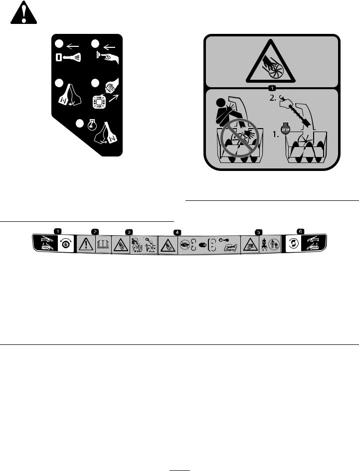
Safety and Instructional Decals
Safety and instruction decals are located near areas of potential danger. Replace damaged or missing decals.
1 2
x 3
3 4
5
120-9805
120-9805
1.Insert the key.
2.Prime the engine 3 times.
3.Engage the choke.
4.Pull the starter cord.
5.Once the engine is running, disengage the choke.
121-1239
Order Part No. 121-1215
121-1240
Order Part No. 120-7194
1.Traction drive—squeeze the lever to engage; release the lever to disengage.
4.Cutting dismemberment hazard, impeller—keep away from moving parts; remove the ignition key and read the instructions before servicing or performing maintenance.
2.Warning—read the Operator’s Manual.
3.Cutting/dismemberment hazard, impeller—do not place your hand in the chute; shut off the engine before leaving the operating position, use the tool to clear the chute.
5.Thrown object hazard—keep bystanders a safe distance away from the snowthrower.
6.Auger/impeller drive—squeeze the lever to engage; release the lever to disengage.
3

121-6817
1.Cutting dismemberment, impeller and cutting dismemberment, auger hazards—keep bystanders a safe distance away from the snowthrower.
121-6823
1. |
Fast |
3. |
Slow |
2. |
Forward speeds |
4. |
Reverse speeds |
|
|
|
|
131-6487
1. Engine—shut off |
3. Fast |
2.Slow
4

Setup
Loose Parts
Use the chart below to verify that all parts have been shipped.
Procedure |
Description |
Qty. |
Use |
|
|
|
|
|
|
1 |
Handle bolt |
2 |
|
|
Curved washer |
2 |
Install the upper handle. |
||
Locknut |
2 |
|
||
|
|
|||
2 |
Hairpin cotter |
2 |
Install the traction-control linkage. |
|
Flat washer |
3 |
|||
|
||||
3 |
Nut |
2 |
|
|
Carriage bolt |
2 |
Install the chute. |
||
Flat washer |
2 |
|
||
|
|
|||
4 |
Carriage bolt |
2 |
Install the chute-control rod. |
|
Locknut |
2 |
|||
|
||||
5 |
No parts required |
– |
Check the engine-oil level. |
|
|
|
|
||
6 |
No parts required |
– |
Check the tire pressure. |
|
|
|
|
||
7 |
No parts required |
– |
Check the skids and scraper. |
|
|
|
|
||
8 |
No parts required |
– |
Check the operation of the traction drive. |
|
|
|
|
1
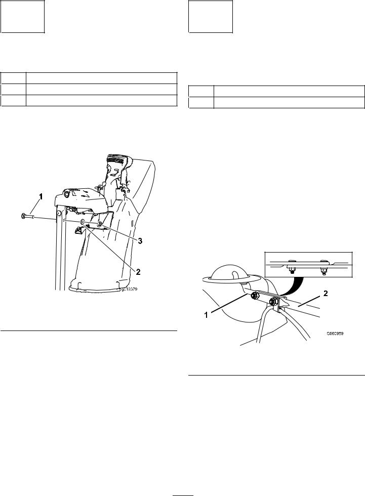
Installing the Upper Handle
Parts needed for this procedure:
2 Handle bolt
2 Curved washer
2 Locknut
Procedure
Figure 4
1.Lift and rotate the upper handle and position it over the lower handle (Figure 4).
2.Install 2 handle bolts, 2 curved washers, and 2 locknuts in the lower-handle holes (Figure 4).
5

2
Installing the Traction-Control
Linkage
Parts needed for this procedure:
2Hairpin cotter
3Flat washer
Procedure
1.Insert the lower end of the rod into the lower link arm so that the bent end of the speed-control rod faces rearward (Figure 5).
Figure 5
2.Secure the lower end of the speed-control rod with a flat washer and a hairpin cotter (Figure 5).
3.Place a flat washer on the trunnion (Figure 6).
|
|
Figure 6 |
|
1. |
Speed-selector lever |
3. |
Inner washer |
2. |
Trunnion |
4. |
Outer washer |
4.Shift the speed-selector lever into Position R2.
5.Rotate the lower link arm fully upward (counterclockwise) as shown in Figure 7.
6
Figure 7
6.Pull up the speed-control rod and insert the trunnion into the hole in the speed-selector lever (Figure 6).
Note: If the trunnion does not fit into the hole when you lift up on the speed-control rod, rotate the trunnion upward or downward on the speed-control rod until it fits.
7.Secure the trunnion and upper end of the speed-control rod with a washer and a hairpin cotter.
Note: For easier installation, look down through the opening in the speed selector (Figure 8).
Figure 8
1.Speed selector
3
Installing the Chute
Parts needed for this procedure:
2 Nut
2 Carriage bolt
2 Flat washer
Procedure
1.Place the chute on the frame and align the discharge chute mount to the chute support.
Figure 9
1. Carriage bolt |
3. Nut |
2.Flat washer
2.Secure the discharge chute mount using 2 bolts, 2 nuts, and 2 flat washers.
4
Installing the Chute-Control
Rod
Parts needed for this procedure:
2 Carriage bolt
2 Locknut
Procedure
1.Unwrap the Quick Stick and rotate it so that it is upright and in the center.
2.Hold the blue trigger cap down and pull the lever fully rearward.
Note: The discharge chute and deflector should face forward. If they do not, hold the blue trigger cap down (but do not move the Quick Stick) and rotate the discharge chute until they do.
3.Align the flattened back end of the long chute-control rod with the flattened front end of the short rod that extends from the control panel so that they nest together (Figure 10).
Figure 10
1. Short rod |
2. Long chute-control rod |
4.Insert the front end of the rod into the opening in the back of the chute-gear cover until it slides into the chute gear (Figure 11).
7
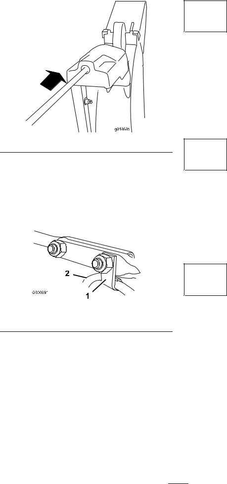
Figure 11
5.Align the holes in the nested ends of the rods and insert 2 carriage bolts (in the loose-parts bag) through the short rod from the left side of the machine (from the operating position).
6.Insert the cable clip that supports the deflector cable onto the forward carriage bolt, and secure the carriage bolts with locknuts from the loose-parts bag (Figure 12).
5
Checking the Engine-Oil Level
No Parts Required
Procedure
Note: Your machine comes with oil in the engine crankcase. Before starting the engine, check the oil level and add oil if necessary.
Refer to Checking the Engine-Oil Level (page 18).
6
Checking the Tire Pressure
No Parts Required
Procedure
The tires are overinflated at the factory for shipping. Reduce the pressure equally in both tires to between 116 and 137 kPa (17 and 20 psi).
Figure 12
1. Cable clip |
2. Deflector cable |
7.Hold the blue trigger cap down and rotate the Quick Stick in a circle to ensure that the chute and deflector operate smoothly.
7
Checking the Skids and
Scraper
No Parts Required
Procedure
Refer to Checking and Adjusting the Skids and Scraper (page 18).
8

8
Checking the Operation of the
Traction Drive
No Parts Required
Procedure

 CAUTION
If the traction drive is not properly adjusted, the machine may move in the direction opposite of what you intended, causing injury and/or property damage.
Carefully check the traction drive and adjust it properly, if necessary.
Note: To check the operation of the traction drive, you must engage the self-propel feature by pinning the wheels in the axle; refer to Freewheeling or Using the Self-Propel Drive (page 11).
1.Start the engine; refer to Starting the Engine (page 12).
2.Move the speed selector to Position R1; refer to Operating the Speed Selector (page 14).
3.Squeeze the left (traction) lever to the handgrip (Figure 13).
Figure 13
The machine should move rearward. If the machine does not move or moves forward, complete the following:
A.Release the traction lever and shut off the engine.
B.Disconnect the trunnion from the speed-selector lever (Figure 6).
C.Turn the trunnion downward (clockwise) on the speed-control rod (Figure 6).
D.Connect the trunnion to the speed-selector lever (Figure 6).
4.Release the traction lever.
5.Move the speed selector to the Position 1; refer to Operating the Speed Selector (page 14).
6.Squeeze the left (traction) lever to the handgrip (Figure 13).
The machine should move forward. If the machine does not move or moves rearward, complete the following:
A.Release the traction lever and shut off the engine.
B.Disconnect the trunnion from the speed-selector lever (Figure 6).
C.Turn the trunnion upward (counterclockwise) on the speed-control rod (Figure 6).
D.Connect the trunnion to the speed-selector lever (Figure 6).
7.If you made any adjustments, repeat this procedure until no adjustments are required.
Important: If the machine moves when the traction lever is in the released position, check the traction cable; refer to Checking and Adjusting the Traction Cable (page 19) or take the machine to an Authorized Service Dealer for service.
9
Loading...