


RESIDENTIAL PRODUCTS
WALK BEHIND MOWER ENGINE SERVICE MANUAL
2012 and Prior LC1P65FA (159cc)
About this Manual
This service manual was written expressly for Toro service technicians. The Toro Company has made every effort to make the information in this manual complete and correct. Basic shop safety knowledge and mechanical/electrical skills are assumed. The Table of Contents lists the systems and the related topics covered in this manual. An electronic version of this service manual is available on the Toro Dealer Portal. We are hopeful that you will find this manual a valuable addition to your service shop. If you have any questions or comments regarding this manual, please contact us at the following address:
The Toro Company
Residential and Landscape Contractor Service Training Department
8111 Lyndale Avenue South
Bloomington, MN 55420

Chapter 1 |
– General Service Information |
|
1 |
|
|
|
|
|
|
Chapter 2 |
- Engine Service / Maintenance |
|
2 |
|
|
|
|
|
|
Chapter 3 |
- Engine Disassembly and Service |
|
3 |
|
|
|
|
|
|
Chapter 4 |
- Electrical |
|
4 |
|
|
|
|
|
|

NOTES:

Chapter 1 – General Service Information |
1 |
|
|
Safety |
2 |
Service Rules |
3 |
Engine Model / Serial Number Location |
3 |
Engine Fastener Torque Specification |
4 |
General Specifications |
4 |
Engine Specifications |
5 |
Troubleshooting |
6 |
1

Safety
Safety Information
This symbol means WARNING or PERSONAL SAFETY INSTRUCTION – read the instruction because it has to do with your safety. Failure to comply with the instruction may result in personal injury or even death.
This manual is intended as a service and repair manual only. The safety instructions provided herein are for troubleshooting, service, and repair of the Toro engine. The Toro mower and operator’s manuals contain safety information and operating tips for safe operating practices.
Avoid Unexpected Engine Start - Turn off engine and disconnect the spark plug before servicing engine.
Avoid Lacerations and Amputations - Stay clear of all moving parts while the engine is running.
Avoid Burns - Do not touch the engine, muffler, or other components which may increase in temperature during operation, while the unit is running or shortly after it has been running.
Avoid Fires and Explosions - Avoid spilling fuel and never smoke while working with any type of fuel or lubricant. Wipe up any spilled fuel or oil immediately. Never remove the fuel cap or add fuel when the engine is running. Always use approved, labeled containers for storing or transporting fuel and lubricants.
Avoid Asphyxiation - Never operate an engine in a confined area without proper ventilation.
Avoid Injury From Batteries - Battery acid is poisonous and can cause burns. Avoid contact with skin, eyes, and clothing. Battery gases can explode. Keep cigarettes, sparks, and flames away from the battery.
Avoid Injury Due To Inferior Parts - Use only original equipment parts to ensure that important safety criteria are met.
Avoid Injury To Bystanders - Always clear the area of bystanders before starting or testing power equipment.
Avoid Injury Due To Projectiles - Always clear the area of sticks, rocks, or any other debris that could be picked up and thrown by the power equipment.
Avoid Modifications - Never alter or modify any part unless it is a factory approved procedure.
2
Service Rules |
1 |
|
|
1.Only use genuine Toro parts and lubrication products.
2.Always install new gaskets, O-rings and seals when assembling engine.
3.Always torque fasteners to specification and in sequence.
4.Always lubricate friction components with clean engine oil or engine assembly lube when assembling engine.
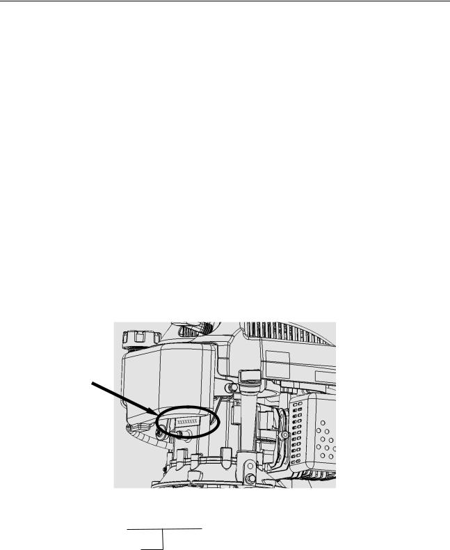
Engine Model / Serial Number Location
The engine model and serial number are stamped into the crankcase, near the fuel tank.
Engine Model and
Serial Numbers
XXX-XXXX XXXXXXXXXXX
|
|
|
|
Engine Model |
|
|
Serial Number |
|
|
||
|
|
|
|
3

Engine Fastener Torque Specifications
Item |
Fastener Size |
Torque |
|
Specification |
|||
|
|
||
|
|
|
|
Cylinder Head Bolts |
M8 |
25 ft-lbs (34 Nm) |
|
|
|
|
|
Connecting Rod Bolts |
M7 |
9.5 ft-lbs (13 Nm) |
|
|
|
|
|
Flywheel Nut |
M14 |
62.5 ft-lbs (85 Nm) |
|
|
|
|
|
Valve Adjust Lock Nut |
M6 |
10 ft-lbs (14 Nm) |
|
|
|
|
|
Pivot Arm Pivot Stud |
M8 |
22 ft-lbs (30 Nm) |
|
|
|
|
|
Crankcase Cover Bolt |
M6 |
7.5 ft-lbs (10 Nm) |
|
|
|
|
|
Muffler Nuts |
M6 |
7.5 ft-lbs (10 Nm) |
|
|
|
|
|
Air Cleaner Nuts |
M6 |
6 ft-lbs (8 Nm) |
|
|
|
|
|
Recoil (Fan Shroud) Nut |
M6 |
6 ft-lbs (8 Nm) |
|
|
|
|
|
Oil Drain Bolt |
M10 |
15.5 ft-lbs (21 Nm) |
|
|
|
|
|
Fuel Tank Bolts / Nuts |
M6 |
7.5 ft-lbs (10 Nm) |
|
|
|
|
|
Governor Arm Pinch Nut |
M6 |
7.5 ft-lbs (10 Nm) |
|
|
|
|
|
Spark Plug |
- |
22 ft-lbs (30 Nm) |
|
|
|
|
|
Ignition and Charge Coil Bolts |
M6 |
7.5 ft-lbs (10 Nm) |
|
|
|
|
|
Electric Starter Motor Bolts |
M6 |
7.5 ft-lbs (10 Nm) |
|
|
|
|
|
|
M5 Bolt / Nut |
4.5 ft-lbs (6 Nm) |
|
|
|
|
|
|
M6 Bolt / Nut |
7.5 ft-lbs (10 Nm) |
|
|
|
|
|
Standard Torque Values |
M8 Bolt / Nut |
19 ft-lbs (26 Nm) |
|
|
|
|
|
|
M10 Bolt / Nut |
28 ft-lbs (38 Nm) |
|
|
|
|
|
|
M12 Bolt / Nut |
41 ft-lbs (55 Nm) |
|
|
|
|
General Specifications
Model |
1P65FA |
|
|
Type |
Single cylinder, 4-Stroke, Forced Air Cooling, OHV |
|
|
Bore x Stroke (mm) |
65×48 |
|
|
Displacement (cc) |
159 |
|
|
Compression Ratio |
8 :1 |
|
|
Lubrication |
Splash |
|
|
Starting |
Recoil and Electric Start |
|
|
Rotation |
Counter-Clockwise (From P.T.O. Side) |
|
|
Ignition System |
Transistorized Magneto Ignition |
|
|
Air Cleaner |
Foam & Paper |
|
|
Fuel Type |
Unleaded Gasoline, 87 Octane |
|
|
Oil Capacity |
Max. Fill: 20 oz (0.59 l) |
|
|
Dimensions (L×W×H) |
371×338×356 (mm) |
|
|
Dry Weight |
26.4 lbs (12 kg) |
|
|
|
4 |

Engine Specifications |
|
|
|
1 |
|
||
|
|
|
|
|
|
|
|
|
|
|
|
|
|
|
|
Part |
Item |
|
Standard |
Service Limit |
|||
|
|
|
|
|
|
||
Engine |
Operating RPM |
2900 – 3100 RPM |
|
||||
|
|
|
|
|
|
||
Cylinder Head |
Warpage |
|
0.00393” (0.10 mm) |
||||
|
|
|
|
|
|
||
Cylinder |
Sleeve Taper / Out of Round |
2.559” (65.0 mm) |
2.566” (65.165 mm) |
||||
(Inside Diameter) |
|||||||
|
|
|
|
|
|||
|
|
|
|
|
|
||
|
Skirt Outside Diameter |
2.558” (64.985 mm) |
2.553” (64.845 mm) |
||||
|
|
|
|
|
|
||
Piston |
Cylinder Clearance |
0.00059 - 0.00196” (0.015-0.05 mm) |
0.00472” (0.12 mm) |
||||
|
|
|
|
|
|
||
Piston Pin Bore Inside Diameter |
0.5118” (13.002 mm) |
0.5137” (13.048 mm) |
|||||
|
|||||||
|
|
|
|
|
|
||
|
Piston Pin Clearance |
0.00007- 0.0005” (0.002-0.014 mm) |
.00314“ |
(0.08 mm) |
|||
|
|
|
|
|
|
||
Piston Pin |
Outside Diameter |
0.5118” (13.0 mm) |
0.51” (12.954 mm) |
||||
|
|
|
|
|
|
||
|
Ring To Groove (Top and Middle) |
0.00059 - 0.00177” (0.015-0.045 mm) |
0.0059” |
(0.15 mm) |
|||
|
|
|
|
|
|
||
Piston Rings |
End Gap (Top and Middle) |
0.0078 - 0.0157” (0.2-0.4 mm) |
0.0393” (1.0 mm) |
||||
|
|
|
|
|
|
||
Width (Top and Middle) |
0.059” (1.5 mm) |
0.0539” |
(1.37 mm) |
||||
|
|||||||
|
|
|
|
|
|
||
|
Width (Oil Ring) |
0.0984” (2.5 mm) |
0.0933” |
(2.37 mm) |
|||
|
|
|
|
|
|
||
|
Small End Inside Diameter |
0.5125” (13.02 mm) |
0.5145” (13.07 mm) |
||||
|
|
|
|
|
|
||
Connecting Rod |
Big End Inside Diameter |
1.0244” (26.02 mm) |
1.0263” (26.07 mm) |
||||
|
|
|
|
|
|
||
Big End Oil Clearance |
0.00157 - 0.00248” (0.04-0.063 mm) |
0.0047” |
(0.12 mm) |
||||
|
|||||||
|
|
|
|
|
|
||
|
Big End Side Clearance |
0.00393 - 0.02755” (0.1-0.7 mm) |
0.0433” (1.1 mm) |
||||
|
|
|
|
|
|
||
Crankshaft |
Crackpin Outside Diameter |
1.0228” (25.98 mm) |
1.0204” (25.92 mm) |
||||
|
|
|
|
|
|
|
|
|
Clearance (cold) |
(Intake) |
0.0039” (0.10 mm) |
|
|||
|
|
|
|
|
|
|
|
Valve |
Clearance (cold) |
(Exhaust) |
0.0059” (0.15 mm) |
|
|||
|
|
|
|
|
|
||
Stem Diameter |
(Intake) |
0.2157” (5.48 mm) |
0.2093” (5.318 mm) |
||||
|
|||||||
|
|
|
|
|
|
|
|
|
Stem Diameter |
(Exhaust) |
0.2141” (5.44 mm) |
0.2076” (5.275 mm) |
|||
|
|
|
|
|
|
||
|
Inside Diameter (Intake, Exhaust) |
0.2165” (5.50 mm) |
0.2193” (5.572 mm) |
||||
|
|
|
|
|
|
||
Valve Guides |
Stem to Guide Clearance (Intake) |
.00039” - 0.0013” (0.01-0.034 mm) |
.00393” |
(0.10 mm) |
|||
|
|
|
|
|
|
||
|
Stem to Guide Clearance (Exhaust) |
0.0019 - 0.0027” (0.05-0.070 mm) |
0.0047” |
(0.12 mm) |
|||
|
|
|
|
|
|
||
Valve Seat |
Seat Width |
0.0314” (0.8 mm) |
0.0787” (2.0 mm) |
||||
|
|
|
|
|
|
||
Valve Spring |
Free Length |
1.2007” (30.5 mm) |
1.1417” |
(29.0 mm) |
|||
|
|
|
|
|
|
||
|
Height (Intake) |
1.0905” (27.7 mm) |
1.0807” (27.45 mm) |
||||
|
|
|
|
|
|
||
Camshaft |
Height (Exhaust) |
1.0925“ (27.75 mm) |
1.0826” (27.50 mm) |
||||
|
|
|
|
|
|
||
|
Journal (Bearing) |
0.5505” (13.984 mm) |
0.5478“ (13.916 mm) |
||||
|
|
|
|
|
|
||
Crankcase Cover |
Camshaft Hole Diameter |
0.5511” (14.0 mm) |
0.553” (14.048 mm) |
||||
|
|
|
|
|
|
||
Crankshaft Hole Diameter |
1.0” (25.4 mm) |
1.00472” |
(25.52 mm) |
||||
|
|||||||
|
|
|
|
|
|
|
|
Spark Plug |
Gap |
|
0.0275 - 0.0314” (0.7-0.8 mm) |
|
|||
|
|
|
|
|
|
||
|
Resistance (Primary) |
1.1-1.6 Ω |
|
||||
|
|
|
|
|
|
||
Ignition Coil |
Resistance (Secondary) |
10.5 KΩ +/- 15% |
|
||||
|
|
|
|
|
|
||
|
Gap to Flywheel |
.01” (0.254 mm) |
|
||||
|
|
|
|
|
|
|
|
NOTE: The only internal parts available for this engine are gaskets and seals.
5

Troubleshooting
Hard Starting / Poor Running
-Incorrect Fuel (Level, Age, Octane, Ethanol Content)
-Fuel System Contamination and / or Carburetor Debris
-Incorrect Oil Level
-Spark Plug (Incorrect Gap, Fouled, Loose or Faulty)
-Air Filter Restriction
-Air Intake System Leaks
-Ignition Coil to Flywheel Gap Incorrect
-Weak / No Spark
-Auto Choke System (Improper Function)
-Choke / Air Vane Linkage
-Operating RPM Incorrect
-Governor Adjustment Incorrect
-Engine Valve Clearance out of Specification
-Low Compression or Excessive Leakdown
Overheating
-Incorrect Oil Level
-Cylinder Head Gasket Leak
-Debris Build-Up Restricting Air Flow
6
Chapter 2 - Engine Service / Maintenance |
2 |
|
Engine Oil Change Procedure |
8 |
|
|
||
Air Cleaner Service |
9 |
|
Spark Plug Service |
10 |
|
Valve Clearance Inspection and Adjustment |
11 |
|
Engine Governor – Zero Point Setting |
11 |
|
Fuel Filter Replacement |
12 |
|
Auto Choke System / Function |
13 |
|
Auto Choke System View |
14 |
|
7

Engine Oil Change Procedure
1.Run engine to warm engine oil.
2.Remove spark plug cap from the spark plug.
NOTE: Ensure fuel system contains no fuel to prevent leakage when the mower is tipped onto its side.
3.Remove the dipstick.
4.Tip the mower onto side with the dipstick on the downward side. Drain the used oil through the oil fill tube into a suitable container.
5.Return the mower to the operating position.
6.Add oil through the dipstick tube. Wipe the dipstick clean and insert it into the dipstick tube to check the oil level.
NOTE: DO NOT screw the dipstick into the dipstick tube to check the oil level
NOTE: DO NOT overfill the engine oil
7.Fully Install the dipstick and hand tighten it securely.
8.Properly dispose of the used engine oil.
Engine Oil Capacity:
Max. Fill: 20 oz (0.59 l)
Engine Oil Type:
SAE 30 or 10W-30 detergent oil. API classification of SF,SG, SH, SJ, SL, or higher.
8

Air Cleaner Service |
2 |
|
|
1.Press the upper latch tabs and rotate the top of the cover outward to open and remove the cover.
2.Remove the paper air filter and the foam pre-filter.
3.Inspect the foam pre-filter, and replace it if damaged or excessively dirty.
4.Inspect the paper air filter.
NOTE: If the paper air filter is excessively dirty, damaged or is wet with oil or fuel, replace it.
5.Remove dirt from the air cleaner body and cover using a moist rag. Do not wipe dirt into the air duct.
6.If the foam pre-filter is reusable, clean it with warm soapy water. Thoroughly rinse and dry foam element.
7.Insert the foam pre-filter and the paper air filter into the air cleaner
8.Properly Install the cover and verify cover latch tabs are fully engaged.
Air Cleaner Base
Paper Element
Air Cleaner
Cover
Foam Element
9

Spark Plug Service
NOTE: Spark plugs of the wrong size or incorrect heat range can cause severe engine damage.
High Voltage Ignition Systems can be Dangerous - Use Caution when Servicing Ignition Systems
1.Disconnect the spark plug cap and thoroughly clean the spark plug area.
2.Remove the spark plug from the engine.
3.Inspect the spark plug for excessively worn electrodes, chips or cracks in the insulator, or excessive deposits.
4.Measure the electrode gap and adjust if necessary. Spark Plug Gap: 0.0275 - 0.0314” (0.7-0.8 mm)
5.Install spark plug and torque to specification - 22 ft-lbs (30 Nm).
6.Fully install the spark plug cap on the plug.
0.0275 - 0.0314”
(0.7-0.8 mm)
10
 Loading...