


Form No. 3386-194 Rev B
Snow Cab Kit
Power Max Snowthrowers
Model No. 127-5960
Installation Instructions

 WARNING
Installing this snow cab onto a Power Max snowthrower without properly installing a counterweight to the front of the snowthrower can cause it to tip backward and fall on the operator, causing injury.
•Do not operate a snowthrower with a snow cab that does not have the proper counterweight.
•Obtain and install a Toro weight kit to the front of the snowthrower in order to balance the added weight of the snow cab.
1
Installing the Snow Cab Frame on the Snowthrower
Parts needed for this procedure:
2 |
U-bracket |
4 |
Washers |
|
|
2 |
End caps |
|
|
2 |
Bolt (1/4 x 1 inch) |
|
|
6 |
Bolt (1/4 x 3/4 inch) |
|
|
2 |
Bolt (1/4 x 1-3/4 inch) |
|
|
10 |
Locknut (1/4 inch) |
1Top frame
1Rear frame
1Horizontal frame
1Left mounting bracket
1Right mounting bracket
2Front posts
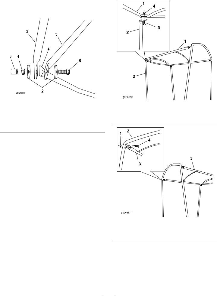
Figure 1
1. |
Handle assembly |
4. |
Bolt, 1/4 x 1-3/4 inch (2) |
2. |
Upper handle nut (2) |
5. |
Locknut (2) |
3. |
U-bracket (2) |
6. |
Left mounting bracket |
2.For installation on Heavy Duty Two-Stage Snowthrowers only: Install the lower front end of the left and right mounting brackets onto the handle assembly using the upper handle mounting nuts you removed in 1 (Figure 1).
3.For installation on Compact Two-Stage Snowthrowers only: Install the left and right spacing bracket, then install the lower front end of the left and right mounting brackets onto the handle assembly using the upper handle mounting nuts you removed in 1 (Figure 2).
Procedure
1.Remove the 2 upper handle nuts (1 on each side) from the snowthrower handle assembly (Figure 1) and save them for 2.
© 2014—The Toro® Company |
Register at www.Toro.com. |
Original Instructions (EN) |
*3386-194* B |
8111 Lyndale Avenue South |
|
Printed in the USA. |
|
Bloomington, MN 55420 |
|
All Rights Reserved |

7.Remove a locknut that you just installed on one of the front corners in 6, install the bottom (straight) end of a front post and a locknut onto the bolt, and tighten the locknut until the front post stays upright (Figure 4).
Figure 2
1. |
Handle assembly |
4. |
Bolt, 1/4 x 1-3/4 inch (2) |
2. |
Upper handle nut (2) |
5. |
Locknut (2) |
3. |
U-bracket (2) |
6. |
Left mounting bracket |
4.Install the other lower end of each mounting bracket onto the handle assembly using a U-bracket, bolt (1/4 x 1-3/4 inch), and locknut (Figure 1).
Note: You may need to squeeze each U-bracket together slightly before installing it onto the handle assembly.
Note: The ends of the U-brackets should face downward.
5.Position the horizontal frame inside the upper ends of the mounting brackets (Figure 3).
Figure 4
1. |
Bolt, 1/4 x 3/4 inch (2) |
4. |
Horizontal frame |
2. |
Upper end of mounting |
5. |
Tab (2) |
|
bracket (2 in the front) |
|
|
3. |
Front post (2) |
6. |
Locknut (2) |
Note: The tabs at the top of the front post should face in toward the operating position.
8.Repeat 7 for the other front post.
9.For each side, align the holes in the frame ends in the rear, insert a bolt (with a washer) through the holes from the inside (Figure 5).
|
Figure 3 |
1. Horizontal frame |
2. Upper end of mounting |
|
bracket (4) |
6.Align each of the 2 holes in the front corners and insert a bolt (1/4 x 3/4 inch) from the outside through each of the holes and install locknuts on the bolts until they are finger-tight.
2
Figure 5
1. |
Mounting bracket end (2) |
3. |
Washer (2) |
2. |
Horizontal frame |
4. |
Bolt, 1/4 x 1 inch (2) |
|
|
|
|
10. Position the rear frame with the top tabs facing forward and the bottom ends to the outside of the other frame ends (Figure 6).
|
|
Figure 6 |
|
|
Figure 7 |
|
|
1. |
Locknut (2) |
5. |
Horizontal frame |
|
|
||
Top frame |
3. |
Bolt, 1/4 x 3/4 inch |
|||||
2. |
Washers (4) |
6. |
1. |
||||
Bolt, 1/4 x 1 inch (2) |
Front post (2) |
4. |
Locknut |
||||
3. |
Rear frame |
7. |
2. |
||||
End cap (2) |
|
|
|
4.Mounting bracket (2)
11.Install a washer and a locknut on each of the bolts and
tighten each locknut until it is finger-tight.
12. Hold the rear frame upright and tighten the locknuts (Figure 6).
Note: Do not overtighten the locknuts, because you will need to adjust the frame assembly to install the top frame and the cover.
13.Attach the top frame to the front post using a bolt and a locknut (Figure 7).
Figure 8
1. |
Locknut (2) |
3. |
Top frame |
2. |
Rear frame |
4. |
Bolt, 1/4 x 3/4 inch |
14. From the operating position, move the entire frame assembly forward until the rear frame is at a 90–degree angle to the horizontal frame (Figure 9).
3
 Loading...