


 Loading...
Toro 22300, 22302, 22302TE, 22304, 22305 Service Manual
...Sitework Systems
Wheeled
Compact Utility Loader
Service Manual
Chain Drive / 4-Paw Gas / 4-Paw Diesel
Form No. 492-9216

ABOUT THIS MANUAL
This service manual was written expressly for Toro service technicians. The Toro Company has made every effort to make the information in this manual complete and correct.
Basic shop safety knowledge and mechanical/electrical skills are assumed. The Table of Contents lists the systems and the related topics covered in this manual.
For service information on drive systems, please refer to the Hydro-Gear BDP-10A/16A/21L Pump service manual (form no. 492-4789), Hydro-Gear P Series Pump service manual (form no. BLN 52503) and Parker-Ross TF wheel motor service manual (form no. 492-4753). For information specific to the engines used on this unit, refer to the appropriate engine manufacturer’s service and repair instructions.
Units covered on in this manual are: Wheeled Chain Drive compact utility loader, model years 1998 - current Wheeled 4-Paw Gas compact utility loader, model years 1999 - current Wheeled 4-Paw Diesel compact utility loader, model years 1999 - current
The manual may also be specified for use on later model products.
The hydraulic power system is precision machinery. Maintain strict cleanliness control during all stages of service and repair. Cover or cap all hose ends and fittings whenever they are exposed. Even a small amount of dirt or other contamination can severely damage the system.
We are hopeful that you will find this manual a valuable addition to your service shop. If you have any questions or comments regarding this manual, please contact us at the following address:
The Toro Company
SWS Technical Services
8111 Lyndale Avenue South
Bloomington, MN 55420
The Toro Company reserves the right to change product specifications or this manual without notice.
Copyright© All Rights Reserved
©2012 The Toro Company

REVISIONS
Revision 000 . . . . . . . . . . . . . 5/01/12
ii |
Toro Wheeled CUL Service Manual |
TABLE OF CONTENTS |
|
ALL UNITS SAFETY INFORMATION |
|
General Information................................................................................................................... |
1/1-1 |
Think Safety First....................................................................................................................... |
1/1-1 |
ALL UNITS SPECIFICATIONS |
|
General Specifications............................................................................................................... |
2/1-1 |
Dimensions................................................................................................................................ |
2/1-2 |
Engine........................................................................................................................................ |
2/1-3 |
Performance............................................................................................................................... |
2/1-4 |
Hydraulic System....................................................................................................................... |
2/1-5 |
Electrical System........................................................................................................................ |
2/1-6 |
Drive System.............................................................................................................................. |
2/1-6 |
Torque Specifications................................................................................................................. |
2/1-7 |
Standard Torque for Dry, Zinc Plated, and Steel Fasteners (Inch Series)................................. |
2/1-8 |
Standard Torque for Dry, Zinc and Steel Fasteners (Metric Series)........................................... |
2/1-9 |
Other Torque Specifications..................................................................................................... |
2/1-10 |
Equivalents and Conversions................................................................................................... |
2/1-11 |
U.S. to Metric Conversions...................................................................................................... |
2/1-12 |
ALL UNITS GENERAL
Raising the Traction Unit 3/1-1 98-9050 Counterbalance Valve Rebuild 3/1-2 99-3040 Counterbalance Valve Rebuild 3/1-3 99-3070 4-Spool Valve Rebuild (Diesel) 3/1-5 99-3072 Selector Valve Rebuild 3/1-13 100-4163 Hydraulic Cylinder Rebuild 3/1-17 104-4221 Flow Divider Valve Rebuild 3/1-29 105-6246 4-Spool Valve Rebuild (Chain Drive) 3/1-33 105-7867 Hydraulic Cylinder Rebuild 3/1-40 108-4710 Hydraulic Tandem Pump Rebuild 3/1-50 98-4732 cross-referenced to 104-7422 4-Spool Valve Rebuild
(used on Chain Drive 22304) 3/1-62 99-3077 Auxiliary Valve Rebuild 3/1-67 99-3077 Auxiliary Valve Removal 3/1-67 99-3077 Auxiliary Valve Assembly 3/1-70
CHAIN DRIVE DRIVE SYSTEM
Drive Chain Replacement 4/1-1 Drive Chain Removal 4/1-1 Drive Chain Installation 4/1-6 Front Axle Replacement 4/1-10 Front Axle Removal 4/1-10 Front Axle Installation 4/1-18 Sprocket & Wheel Hub 4/1-28 Sprocket & Chain Inspection 4/1-28 Rear Sprocket & Wheel Hub Removal 4/1-30 Sprocket Replacement 4/1-35 Sprocket Removal 4/1-35 Sprocket Installation 4/1-36 Rear Sprocket & Wheel Hub Installation 4/1-37 Front Sprocket & Wheel Hub Removal 4/1-40 Front Axle Hub Rebuild 4/1-46 Front Sprocket & Wheel Hub Installation 4/1-48
Toro Wheeled CUL Service Manual |
TOC-1 |

TABLE OF CONTENTS
CHAIN DRIVE DRIVE SYSTEM cont.
Checking the Drive Chain Tension 4/1-54 Adjusting the Drive Chain Tension 4/1-55 Wheel Motor Replacement 4/1-56 Wheel Motor Removal 4/1-56 Wheel Motor Installation 4/1-64
CHAIN DRIVE HYDRAULICS
Counterbalance Valve Replacement 4/2-1 Counterbalance Valve Removal 4/2-1 Counterbalance Valve Installation 4/2-6 4-Spool Valve Replacement 4/2-11 4-Spool Valve Removal 4/2-11 4-Spool Valve Installation 4/2-17 Hydraulic Filter Head Replacement 4/2-24 Hydraulic Filter Head Removal 4/2-24 Hydraulic Filter Head Installation 4/2-26 Auxiliary Valve & Selector Valve Replacement 4/2-28 Auxiliary Valve & Selector Valve Removal 4/2-28 Auxiliary Valve & Selector Valve Installation 4/2-31 Lift Cylinder Replacement 4/2-35 Lift Cylinder Removal 4/2-35 Lift Cylinder Installation 4/2-38 Tilt Cylinder Replacement (New Style) 4/2-41 Tilt Cylinder Removal 4/2-41 Tilt Cylinder Installation 4/2-43
CHAIN DRIVE LOADER ARM
Loader Arm Replacement 4/3-1
Loader Arm Removal 4/3-1
Loader Arm Installation 4/3-7
CHAIN DRIVE GAS ENGINE
Gas Engine Replacement 4/4-1 Gas Engine Removal 4/4-1 Gas Engine Installation 4/4-14
CHAIN DRIVE ELECTRICAL
Ignition Switch 4/5-1 Purpose 4/5-1 Location 4/5-1 How It Works 4/5-1 Testing 4/5-1
Relay 4/5-2 Purpose 4/5-2 Location 4/5-2 How It Works 4/5-2 Testing 4/5-2
Fuses 4/5-3 Purpose 4/5-3 Location 4/5-3 How It Works 4/5-3 Testing 4/5-3
TOC-2 |
Toro Wheeled CUL Service Manual |

TABLE OF CONTENTS
CHAIN DRIVE ELECTRICAL cont.
Auxiliary Neutral Switch 4/5-4 Purpose 4/5-4 Location 4/5-4 How It Works 4/5-4 Testing 4/5-4
Hour Meter 4/5-5 Purpose 4/5-5 Location 4/5-5 How It Works 4/5-5 Testing 4/5-5
Battery Replacement 4/5-6 Battery Removal 4/5-6 Battery Installation 4/5-7 Electrical Schematic 4/5-9 22311 / 22317 4/5-9
4-PAW GAS DRIVE SYSTEM
Front Wheel Motor Replacement 5/1-1 Front Wheel Motor Removal 5/1-1 Front Wheel Motor Installation 5/1-7 Rear Wheel Motor Replacement 5/1-13 Rear Wheel Motor Removal 5/1-13 Rear Wheel Motor Installation 5/1-20
4-PAW GAS HYDRAULICS
Left Hand Counterbalance Valve Replacement 5/2-1
Left Hand Counterbalance Valve Removal 5/2-1
Left Hand Counterbalance Valve Installation 5/2-7
Right Hand Counterbalance Valve Replacement 5/2-11
Right Hand Counterbalance Valve Removal 5/2-11
Right Hand Counterbalance Valve Installation 5/2-18
4-PAW GAS LOADER ARM
Loader Arm Replacement 5/3-1
Loader Arm Removal 5/3-1
Loader Arm Installation 5/3-7
4-PAW GAS ENGINE
Engine Replacement 5/4-1
Engine Removal 5/4-1
Engine Installation 5/4-13
4-PAW GAS ELECTRICAL
Ignition Switch (P/N 103990) 5/5-1 Purpose 5/5-1 Location 5/5-1 How It Works 5/5-1 Testing 5/5-1
Relay 5/5-2 Purpose 5/5-2
Toro Wheeled CUL Service Manual |
TOC-3 |

TABLE OF CONTENTS
4-PAW GAS ELECTRICAL cont.
Start Relay 5/5-2 Kill Relay 5/5-2 Location 5/5-2 How It Works 5/5-2 Testing 5/5-3 Fuses 5/5-3 Purpose 5/5-3 Location 5/5-3 How It Works 5/5-4 Testing 5/5-4 Neutral Safety Switch 5/5-4 Purpose 5/5-4 Location 5/5-4 How It Works 5/5-4 Testing 5/5-4 Auxiliary Neutral Switch 5/5-5 Purpose 5/5-5 Location 5/5-5 How It Works 5/5-5 Testing 5/5-5 Hour Meter/Tachometer 5/5-6 Purpose 5/5-6 Location 5/5-6 How It Works 5/5-6 Testing 5/5-6 Electrical Schematics 5/5-7 22318 - 2010, 2009, 2008, 2007 5/5-7 22318 - 2006, 2005 5/5-8 22312 - 2005, 2004, 2003 5/5-8 22312 - 2004, 2003 5/5-9 22305 - 2002, 2001 5/5-9 22305 - 2000, 1999 5/5-10
4-PAW DIESEL DRIVE SYSTEM
Front Wheel Motor Replacement 6/1-1 Front Wheel Motor Removal 6/1-1 Front Wheel Motor Installation 6/1-7 Rear Wheel Motor Replacement 6/1-13 Rear Wheel Motor Removal 6/1-13 Rear Wheel Motor Installation 6/1-20
4-PAW DIESEL HYDRAULICS
4-Spool Valve Replacement (Diesel) 6/2-1 4-Spool Valve Removal 6/2-1 4-Spool Valve Installation 6/2-8 Hydraulic Auxiliary, Selector & Flow Divider Valves 6/2-14 Hydraulic Auxiliary, Selector & Flow Divider Valves Removal 6/2-14 Hydraulic Auxiliary, Selector & Flow Divider Valves Installation 6/2-20 Hydraulic Lift Cylinder Replacement (Old Style) 6/2-24 Hydraulic Lift Cylinder Removal 6/2-24 Hydraulic Lift Cylinder Installation 6/2-28
TOC-4 |
Toro Wheeled CUL Service Manual |

TABLE OF CONTENTS
4-PAW DIESEL HYDRAULICS cont.
Hydraulic Tilt Cylinder Replacement (Old Style) 6/2-30 Hydraulic Tilt Cylinder Removal 6/2-30 Hydraulic Tilt Cylinder Installation 6/2-32 Left Hand Counterbalance Valve Replacement 6/2-35 Left Hand Counterbalance Valve Removal 6/2-35 Left Hand Counterbalance Valve Installation 6/2-39 Right Hand Counterbalance Valve Replacement 6/2-43 Right Hand Counterbalance Valve Removal 6/2-43 Right Hand Counterbalance Valve Installation 6/2-47 Hydraulic Tandem Pump Replacement 6/2-53 Hydraulic Tandem Pump Removal 6/2-53 Hydraulic Tandem Pump Installation 6/2-57
4-PAW DIESEL LOADER ARM
Loader Arm Replacement 6/3-1
Loader Arm Removal 6/3-1
Loader Arm Installation 6/3-7
4-PAW DIESEL ENGINE
Engine Replacement 6/4-1 Engine Removal 6/4-1 Engine Installation 6/4-26 Checking the Alternator Belt Tension 6/4-60 Fan Belt Replacement 6/4-61 Fan Belt Removal 6/4-61 Fan Belt Installation 6/4-66 Fan Replacement 6/4-72 Fan Removal 6/4-72 Fan Installation 6/4-72 Fuel Shut Down Solenoid Replacement 6/4-73 Fuel Shut Down Solenoid Removal 6/4-73 Fuel Shut Down Solenoid Installation 6/4-74 Glow Plug Replacement 6/4-76 Glow Plug Removal 6/4-76 Glow Plug Installation 6/4-77 Muffler Replacement 6/4-77 Muffler Removal 6/4-77 Muffler Installation 6/4-84 Radiator Replacement 6/4-92 Radiator Removal 6/4-92 Radiator Installation 6/4-97 Radiator Mount Replacement 6/4-101 Radiator Mount Removal 6/4-101 Radiator Mount Installation 6/4-102 Pump Mount Assembly Rebuild 6/4-103 Fan Drive Pulley, Rubber Coupler & Flywheel Adapter Replacement 6/4-109 Fan Drive Pulley, Rubber Coupler & Flywheel Adapter Removal 6/4-109 Fan Drive Pulley, Rubber Coupler & Flywheel Adapter Installation 6/4-113
Toro Wheeled CUL Service Manual |
TOC-5 |

TABLE OF CONTENTS
4-PAW DIESEL ELECTRICAL
Ignition Switch 6/5-1 Purpose 6/5-1 Location 6/5-1 How It Works 6/5-1 Testing 6/5-1
Relay 6/5-2 Purpose 6/5-2 Location 6/5-2 How It Works 6/5-2 Testing 6/5-3
Fuses 6/5-4 Purpose 6/5-4 Location 6/5-4 How It Works 6/5-4 Testing 6/5-4
Neutral Safety Switches 6/5-5 Purpose 6/5-5 Location 6/5-5 How It Works 6/5-5 Testing 6/5-5
Auxiliary Neutral Switch 6/5-6 Purpose 6/5-6 Location 6/5-6 How It Works 6/5-6 Testing 6/5-6
Hour Meter 6/5-7 Purpose 6/5-7 Location 6/5-7 How It Works 6/5-7 Testing 6/5-7
Indicator Lights 6/5-8 Purpose 6/5-8 Location 6/5-8 Engine Oil Pressure Light 6/5-8 Battery Light 6/5-8 Engine Temperature Light 6/5-8 Glow Plug Indicator Light 6/5-8 Testing Indicator Lights 6/5-9 Glow Controller 6/5-10 Purpose 6/5-10 Location 6/5-10 How It Works 6/5-10 Testing 6/5-11 Fuel Shut Down Solenoid 6/5-12 Purpose 6/5-12 Location 6/5-12 How It Works 6/5-12 Testing 6/5-13 Troubleshooting 6/5-13 Electrical Schematics 6/5-14 22303 -2001, 2000, 1999 6/5-14 22303 - 2006, 2005, 2003, 2002 6/5-15
TOC-6 |
Toro Wheeled CUL Service Manual |

SAFETY INFORMATION
General Information
This symbol means WARNING or
!PERSONAL SAFETY INSTRUCTION - read the instruction because it has to do with your safety. Failure to comply with the instruction may result in personal injury or even death.
This manual is intended as a service and repair manual only. The safety instructions provided herein are for troubleshooting, service, and repair of the Sitework Systems wheeled compact utility loader.
The wheeled loader and attachment operator’s manual contain safety information and operating tips for safe operating practices. Operator’s manuals are available on line at www.toro.com or:
The Toro Company
Publications Department
8111 Lyndale Avenue South
Bloomington, MN 55420
Think Safety First
Avoid unexpected starting of engine...
Always turn off the engine and disconnect the spark plug wire(s) before cleaning, adjusting, or repair.
Avoid lacerations and amputations...
Stay clear of all moving parts whenever the engine is running. Treat all normally moving parts as if they were moving whenever the engine is running or has the potential to start.
Avoid burns...
Do not touch the engine, muffler, or other components which may increase in temperature during operation, while the unit is running or shortly after it has been running.
Avoid fires and explosions...
Avoid spilling fuel and never smoke while working with any type of fuel or lubricant. Wipe up any spilled fuel or oil immediately. Never remove the fuel cap or add fuel when the engine is running. Always use approved, labeled containers for storing or transporting fuel and lubricants.
Avoid asphyxiation...
Never operate an engine in a confined area without proper ventilation.
Avoid injury from batteries...
Battery acid is poisonous and can cause burns. Avoid contact with skin, eyes, and clothing. Battery gases can explode. Keep cigarettes, sparks, and flames away from the battery.
Avoid injury due to inferior parts...
Use only original equipment parts to ensure that important safety criteria are met.
Avoid injury to bystanders...
Always clear the area of bystanders before starting or testing powered equipment.
Avoid injury due to projectiles...
Always clear the area of sticks, rocks, or any other debris that could be picked up and thrown by the powered equipment.
Avoid modifications...
Never alter or modify any part unless it is a factory approved procedure.
Avoid unsafe operation...
Always test the safety interlock system after making adjustments or repairs on the machine. Refer to the Electrical section in this manual for more information.
Toro Wheeled CUL Service Manual |
1/1-1 |
SAFETY INFORMATION
Hydraulics Safety
•Inspect all hydraulic line connectors and fittings. Make sure all hydraulic hoses and lines are in good condition before applying pressure to the system.
•Keep body and hands away from pin hole leaks or nozzles that eject high pressure hydraulic fluid. Use cardboard or paper to find hydraulic leaks. Hydraulic fluid escaping under pressure can penetrate the skin and cause injury. Fluid accidentally injected into the skin must be surgically removed within a few hours by a doctor or gangrene may occur.
•Before disconnecting or performing any work on the hydraulic system, lower the loader arm/attachment to the ground and stop the engine so all pressure is relieved.
•Be sure you understand a service procedure before working on the machine.
1/1-2 |
Toro Wheeled CUL Service Manual |

SPECIFICATIONS
General Specifications
Model |
220 |
|
222 |
220D, 320D |
322 |
|
323 |
|||||
22311 |
|
22317 |
|
22300 |
22302 |
22305 |
|
22312 |
|
22318 |
||
|
|
|
|
|
22304 |
22303 |
|
|
|
|
|
|
|
|
|
|
|
|
|
|
|
|
|
Champion |
|
|
|
|
|
|
|
|
|
|
|
|
Premium |
|
|
|
|
|
|
All Years: |
|
All years: |
|
|
|
Gold |
|
|
|
|
|
|
|
Champion |
|
|
|
2071 or |
||
|
|
|
|
|
Champion |
|
|
Champion |
|
|||
|
|
|
|
|
|
RC12YC |
|
|
Champion |
|||
|
|
|
|
|
RC12YC |
|
|
Premium |
|
|||
|
Champion Premium Gold |
|
|
(or |
|
|
RC12YC |
|||||
|
|
(or |
|
|
Gold 2071 |
|
||||||
Spark plug |
2071 or |
|
|
equivalent) |
|
|
(or |
|||||
|
equivalent) |
n/a |
|
or Champion |
|
|||||||
Champion RC12YC |
|
or |
|
|
equivalent) |
|||||||
|
(or equivalent) |
|
or 2001: |
|
2001/2002: |
|
RC12YC |
|
or 2010: |
|||
|
|
Champion |
|
|
(or |
|
||||||
|
|
|
|
|
|
Champion |
|
|
Champion |
|||
|
|
|
|
|
Premium |
|
|
equivalent) |
|
|||
|
|
|
|
|
|
Premium |
|
|
XC12YC |
|||
|
|
|
|
|
Gold 2071 |
|
|
|
|
|||
|
|
|
|
|
|
Gold 2071 |
|
|
|
(RFI type) |
||
|
|
|
|
|
|
|
|
|
|
|||
|
|
|
|
|
|
|
|
|
|
|
(or |
|
|
|
|
|
|
|
|
|
|
|
|
equivalent) |
|
Spark plug |
|
0.030” (0.76mm) |
|
n/a |
|
0.030” (0.76mm) |
|
|||||
Gap |
|
|
|
|
||||||||
|
|
|
|
|
|
|
|
|
|
|
||
Fuel Tank |
|
|
4.0 gallon (15.1 liter) |
|
8.0 gallon (30.2 liter) 2 tanks, |
|||||||
Capacity |
|
|
|
4 gallons (15.1 liters) each |
||||||||
|
|
|
|
|
|
|||||||
Fuel |
On the |
|
In fuel line |
|
On the |
In fuel line |
On the |
|
|
|
|
|
bottom of |
|
|
bottom of |
bottom of |
|
In-line near each tank |
||||||
Shut-off |
|
near tank |
|
near tank |
|
|||||||
the fuel tank |
|
|
the fuel tank |
each tank |
|
|
|
|
||||
|
|
|
|
|
|
|
|
|
||||
|
|
|
|
|
|
3 micron |
|
|
|
|
|
|
Fuel Filter |
|
|
In-line |
|
filtration |
|
|
In-line |
|
|||
|
|
|
rating |
|
|
|
||||||
15 micron filtration rating |
15 micron filtration rating |
|||||||||||
|
w/water |
|||||||||||
|
|
|
|
|
|
|
|
|
|
|
||
|
|
|
|
|
|
separator |
|
|
|
|
|
|
Fuel Pump |
|
|
Vacuum pulse |
|
mechanical |
|
|
Vacuum pulse |
|
|||
Toro Wheeled CUL Service Manual |
2/1-1 |

SPECIFICATIONS
Dimensions
A. |
Overall operating height, fully raised / 91.2” |
I. |
Bucket rollback, fully raised / 97º |
|
(2317mm) |
J. |
Wheelbase / 28.0” (711mm) |
B. |
Hinge pin height, fully raised / 66.0” (1676mm) |
K. |
Overall width / 40.5” (1029mm) |
C. |
Overall height / 48.7” (1237mm) |
X. |
Ground Clearance, front / 5.8” (147mm) |
D. |
Overall length / 82.2” (2088mm) |
X. |
Ground Clearance, rear / 5.8” (147mm) |
E. |
Dump angle / 34º |
X. |
Reach, maximum / 28.0” (711mm) |
F. |
Dump height / 47.0” (1194mm) |
X. |
Bucket rollback, carry position / 20º |
G. |
Reach, fully raised / 26.0” (660mm) |
|
|
H. |
Bucket rollback, ground position / 19º |
X. = Dimension not shown |
|
|
|
|
I |
|
|
|
E |
|
|
|
A |
|
|
G |
B |
|
|
|
F |
|
C |
|
|
|
|
|
H |
K |
J |
D |
|
|
|
||
|
|
|
|
|
|
Fig A |
99-8886 |
2/1-2 |
Toro Wheeled CUL Service Manual |

|
|
|
|
|
|
|
|
|
SPECIFICATIONS |
||||||
Engine |
|
|
|
|
|
|
|
|
|
|
|
|
|
|
|
|
|
|
|
|
|
|
|
|
|
|
|
|
|
|
|
Model |
|
|
|
|
|
Specifications |
|
|
|
|
|
||||
220 |
|
22311 |
|
Kohler Command model CH20S, 4-cycle, air cooled, 2 cylinder, horizontal crankshaft, over |
|||||||||||
|
22317 |
|
head valves, 12VDC solenoid shift electric starter, 15 amp alternator and voltage regulator, |
||||||||||||
|
|
|
|
high capacity air cleaner |
|
|
|
|
|
|
|
|
|||
222 |
|
22300 |
|
Kohler Command CH22, 4-cycle, air cooled 2 cylinder, horizontal crankshaft, overhead valve, |
|||||||||||
|
22304 |
|
hydraulic valve lifters, cast iron cylinder liners, 12VDC solenoid shift electric starter, 15 amp |
||||||||||||
|
|
|
|
alternator and voltage regulator, high capacity air cleaner |
|
|
|
|
|||||||
220D |
|
22302 |
|
Kubota Super Mini Diesel model D722-E, High capacity dry-type remote air cleaner |
|
||||||||||
320D |
|
22303 |
|
|
|
|
|
|
|
|
|
|
|
|
|
322 |
|
22305 |
|
Kohler Command CH22, 4-cycle, air cooled, 2 cylinder, horizontal crankshaft, overhead valve, |
|||||||||||
|
|
hydraulic valve lifters, cast iron cylinder liners, 12VDC solenoid shift electric starter, 15 amp |
|||||||||||||
|
|
|
|
alternator and voltage regulator, high capacity air cleaner |
|
|
|
|
|||||||
323 |
|
22312 |
|
Kohler Command CH23, 4-cycle, air cooled, 2 cylinder, horizontal crankshaft, overhead valve, |
|||||||||||
|
22318 |
|
hydraulic valve lifters, cast iron cylinder liners, 12VDC solenoid shift electric starter, 15 amp |
||||||||||||
|
|
|
|
alternator and voltage regulator, high capacity air cleaner |
|
|
|
|
|||||||
|
|
|
|
|
|
|
|
|
|
|
|
|
|
|
|
Model |
|
|
220 |
|
222 |
220D, 320D |
|
322 |
|
323 |
|
||||
|
22311 |
|
22317 |
|
22300 |
22302 |
|
22305 |
|
22312 |
|
22318 |
|||
|
|
|
|
|
|
|
|
22304 |
22303 |
|
|
|
|
|
|
Compression |
|
|
8.5:1 |
|
|
23.5:1 |
|
|
8.5:1 |
|
|
||||
Ratio |
|
|
|
|
|
|
|
|
|
||||||
|
|
|
|
|
|
|
|
|
|
|
|
|
|
||
Displacement |
|
|
38.1 in3 (624cm3) |
|
43.88 in3 |
|
38.1 in3 |
|
41.0 in3 (674cm3) |
||||||
|
|
|
(719 cm3) |
|
(624cm3) |
|
|||||||||
Bore |
|
|
|
|
3.03” (77mm) |
|
2.64” |
|
3.03” |
|
3.15” (80mm) |
||||
|
|
|
|
|
(67mm) |
|
(77mm) |
|
|||||||
|
|
|
|
|
|
|
|
|
|
|
|
|
|
||
Stroke |
|
|
|
|
2.64” (67mm) |
|
2.68” |
|
|
|
2.64” (67mm) |
|
|||
|
|
|
|
|
(68mm) |
|
|
|
|
||||||
|
|
|
|
|
|
|
|
|
|
|
|
|
|
|
|
|
|
|
|
|
|
|
|
22 HP |
20 HP |
|
22 HP |
|
|
|
|
Power (RPM) |
|
20 HP (14.9kW) |
|
(16.4kW) |
(14.9kW) |
|
(16.4kW) |
|
23 HP (17.2kW) |
||||||
|
@ 3600 (Gross) |
|
@ 3600 |
@ 3600 |
|
@ 3600 |
|
@ 3600 (Gross) |
|||||||
|
|
|
|
|
|
|
|||||||||
|
|
|
|
|
|
|
|
(Gross) |
(Gross) |
|
(Gross) |
|
|
|
|
Peak Torque |
|
|
|
|
|
|
36.8 ft-lbs |
|
|
|
|
|
|
||
|
32 ft-lbs (43 Nm) @ 2500 (Gross) |
(50 Nm) |
|
33 ft-lbs (45 Nm) @ 2500 (Gross) |
|||||||||||
(RPM) |
|
|
@ 2600 |
|
|||||||||||
|
|
|
|
|
|
|
|
|
|
|
|
|
|||
|
|
|
|
|
|
|
|
|
(Gross) |
|
|
|
|
|
|
No-load Speed |
|
|
|
|
|
|
3700 |
|
|
|
|
|
|
||
|
|
3600 ± 75 |
|
|
+50/-100 |
|
|
3600 ± 75 |
|
|
|||||
(RPM) |
|
|
|
|
|
|
|
|
|
||||||
|
|
|
|
|
|
|
(Installed) |
|
|
|
|
|
|
||
|
|
|
|
|
|
|
|
|
|
|
|
|
|
|
|
Idle Speed (RPM) |
|
1400 ± 200 |
|
1200 ± 75 |
1300 ± 100 |
|
1200 ± 75 |
|
1400 ± 200 |
||||||
Oil Capacity |
|
|
|
|
|
|
0.84 US |
|
|
|
|
|
|
||
|
2 quarts (1.9 L) with filter |
gallons |
|
|
2 quarts (1.9 L) |
|
|||||||||
|
|
|
|
|
|
|
|
|
(3.2 L) |
|
|
|
|
|
|
Dry Weight |
|
|
|
|
90 lbs (41kg) |
|
154.3 lbs |
|
|
|
90 lbs (41kg) |
|
|||
|
|
|
|
|
(70kg) |
|
|
|
|
||||||
|
|
|
|
|
|
|
|
|
|
|
|
|
|
|
|
Toro Wheeled CUL Service Manual |
2/1-3 |

SPECIFICATIONS
Performance
Model |
220 |
222 |
|
220D, 320D |
|
322 |
|
323 |
||
22311 |
22317 |
22300 |
|
22302 |
|
22305 |
22312 |
|
22318 |
|
|
|
|
22304 |
|
22303 |
|
|
|
|
|
Tip |
|
|
760 lbs (345kg) w/o operator |
|
|
|
||||
Capacity |
|
|
|
|
|
|||||
|
|
|
1030 lbs (467kg) with |
|
|
|
|
|||
(per |
|
|
|
|
|
|
|
|||
|
|
200 lbs (91kg) operator |
|
|
|
|||||
SAE J732) |
|
|
|
|
|
|||||
|
|
|
|
|
|
|
|
|
|
|
Operating |
|
|
|
|
|
|
|
|
|
|
Capacity |
|
|
380 lbs (172kg) w/o operator |
|
|
|
||||
(per |
|
|
515 lbs (234kg) with 200 lbs (91kg) operator |
|
|
|
||||
SAE J818) |
|
|
|
|
|
|
|
|
|
|
|
0-3 mph |
0-3.7 mph |
|
|
|
|
|
|
|
0-3.7 mph |
|
(0-4.8km/hr) |
(0-6.0km/hr) |
|
|
0-3 mph (0-4.8km/hr) |
|
|
(0-6.0km/hr) |
||
Speed |
forward or |
forward or |
|
|
|
|
forward or |
|||
|
|
forward or reverse |
|
|
||||||
reverse |
reverse |
|
|
|
|
reverse |
||||
|
|
|
(infinitely variable) |
|
|
|||||
|
(infinitely |
(infinitely |
|
|
|
|
(infinitely |
|||
|
|
|
|
|
|
|
|
|||
|
variable) |
variable) |
|
|
|
|
|
|
|
variable) |
|
|
|
|
|
1722 lbs |
|
|
|
|
|
|
|
|
|
|
(781kg) w/o |
|
|
|
|
|
Weight |
1430 lbs (649kg) w/o attachment |
|
attachment |
|
1567 lbs (711kg) w/o attachment |
|||||
1576 lbs (715kg) with std. bucket |
|
1868 lbs |
|
1713 lbs (777kg) with std. bucket |
||||||
|
|
|
||||||||
|
|
|
|
|
(847kg) with |
|
|
|
|
|
|
|
|
|
|
std. bucket |
|
|
|
|
|
2/1-4 |
Toro Wheeled CUL Service Manual |

SPECIFICATIONS
Hydraulic System
Model |
220 |
222 |
|
220D, 320D |
|
322 |
|
323 |
||
22311 |
22317 |
22300 |
|
22302 |
|
22305 |
22312 |
|
22318 |
|
|
|
|
22304 |
|
22303 |
|
|
|
|
|
|
3000 psi |
3250 psi |
3000 psi |
|
3225 psi |
|
|
|
|
3250 psi |
Pressure |
(207 bar) |
(224 bar) |
(207 bar) |
|
(222 bar) |
|
3000 psi (207 bar) |
|
(224 bar) |
|
system relief |
system relief |
system relief |
|
system relief |
|
system relief pressure |
|
system relief |
||
|
|
|
|
|||||||
|
pressure |
pressure |
pressure |
|
pressure |
|
|
|
|
pressure |
Low Flow |
3.7 GPM |
4.0 GPM |
|
|
3.7 GPM (14.0 L/min) |
|
|
4.0 GPM |
||
(14.0 L/min) |
(15.3 L/min) |
|
|
|
|
(15.3 L/min) |
||||
|
|
|
|
|
|
|
|
|||
High Flow |
8.5 GPM |
10.8 GPM |
|
|
|
|
|
|
|
10.8 GPM |
(@3600 |
(32.2 L/min) |
(40.9 L/min) |
|
|
8.5 GPM (32.2 L/min) |
|
|
(40.9 L/min) |
||
RPM) |
|
|
|
|
|
|
|
|
|
|
Hydraulic |
|
|
Tandem Gear Pump |
|
|
|
||||
Pump |
|
|
|
|
|
|||||
|
|
|
|
|
|
|
|
|
|
|
|
0.55 & 0.24 |
0.69 & 0.26 |
|
|
|
|
|
|
|
0.69 & 0.26 |
Displacements |
in3/rev |
in3/rev |
|
|
0.55 & 0.24 in3/rev |
|
|
in3/rev |
||
(9.0 &4.0 |
(11.2 &4.3 |
|
|
(9.0 &4.0 cm3/rev) |
|
|
(11.2 &4.3 |
|||
|
|
|
|
|
||||||
|
cm3/rev) |
cm3/rev) |
|
|
|
|
|
|
|
cm3/rev) |
Hydraulic |
|
|
|
|
|
|
|
|
|
|
Tank |
|
|
14.8 gallon (56.0 L) |
|
|
|
||||
Capacity |
|
|
|
|
|
|
|
|
|
|
Hydraulic |
|
|
Spin-on 10 micron nom. Filtration rating |
|
|
|
||||
Filter |
|
|
|
|
|
|||||
|
|
|
|
|
|
|
|
|
|
|
|
|
|
|
|
SAE10W-30 |
|
|
|
|
|
Hydraulic |
SAE10W-30 or 15W-40 |
|
|
or 15W-40 |
|
|
SAE10W-30 or 15W-40 |
|||
Mobil 424 |
|
diesel oil |
|
Mobil 424 |
||||||
diesel oil (API Service |
|
|
diesel oil (API Service |
|||||||
Fluid |
hydraulic oil |
|
(API Service |
|
hydraulic oil |
|||||
CH-4 or higher) |
|
|
CH-4 or higher) |
|||||||
|
|
|
CH-4 or |
|
|
|||||
|
|
|
|
|
|
|
|
|
|
|
|
|
|
|
|
higher) |
|
|
|
|
|
Hydraulic |
|
|
|
|
2 loader arm |
|
|
|
|
|
Cylinders |
|
|
|
|
1 bucket curl |
|
|
|
|
|
Auxiliary |
|
|
|
Flush face type |
|
|
|
|
||
Connectors |
|
|
|
|
|
|
|
|||
|
|
|
|
|
|
|
|
|
|
|
Toro Wheeled CUL Service Manual |
2/1-5 |

SPECIFICATIONS
Electrical System
Model |
220 |
222 |
220D, 320D |
322 |
|
323 |
|||
22311 |
22317 |
22300 |
22302 |
22305 |
22312 |
|
22318 |
||
|
|
|
22304 |
22303 |
|
|
|
|
|
|
12 volt, |
12 volt, |
12 volt, |
12 volt, |
12 volt, |
|
|
|
|
Battery |
380cca min. |
340cca min. |
380cca min. |
435cca |
380cca min. |
12 volt, 340cca min. @ |
|||
@ |
@ |
@ |
@ |
@ |
0ºF (-18ºC) |
||||
|
|||||||||
|
0ºF (-18ºC) |
0ºF (-18ºC) |
0ºF (-18ºC) |
0ºF (-18ºC) |
0ºF (-18ºC) |
|
|
|
|
Alternator |
|
|
|
12 VDC |
|
|
|
|
|
12 VDC 15 amp with regulator |
14.0 amp |
12 VDC 15 amp with regulator |
|||||||
|
|
|
|
w/regulator |
|
|
|
|
|
|
|
|
|
|
Auxiliary |
|
|
|
|
|
|
|
|
Auxiliary |
power |
|
|
|
|
|
|
|
|
control lever |
|
|
|
||
|
|
|
|
& traction |
|
|
|
||
Interlock |
Auxiliary power control lever must be |
must be |
Auxiliary and traction |
||||||
valves |
|||||||||
in neutral position for starting engine |
in neutral |
valves neutral to start |
|||||||
|
neutral to |
||||||||
|
|
|
|
position |
|
|
|
||
|
|
|
|
start |
|
|
|
||
|
|
|
|
for starting |
|
|
|
||
|
|
|
|
|
|
|
|
||
|
|
|
|
|
engine |
|
|
|
|
Fuses |
|
25 amp |
|
30 amp |
|
25 amp |
|
|
|
|
|
10 amp |
|
|
|
||||
|
30 amp |
|
|
30 amp |
|
|
|||
|
|
|
25 amp |
|
|
|
|||
|
|
|
|
|
|
|
|
||
|
Hourmeter |
Hourmeter |
Hourmeter |
|
Hourmeter |
Hourmeter / tachometer |
|||
Gages |
with service |
Warning |
|||||||
on back of |
on back of |
on back of |
with service reminder |
||||||
|
control panel |
reminder |
control panel |
light cluster |
control panel |
indicator |
|||
|
|
indicator |
|
|
|
|
|
|
|
Drive System
Model |
|
220 |
222 |
220D, 320D |
322 |
|
323 |
||
22311 |
|
22317 |
22300 |
22302 |
22305 |
22312 |
|
22318 |
|
|
|
|
|
22304 |
22303 |
|
|
|
|
Chain Drive |
X |
|
X |
X |
|
|
|
|
|
4-Paw |
|
|
|
|
X |
X |
X |
|
X |
Chain Drive Models:
All four wheels are powered. The two rear wheels are individually driven by hydraulic rotor vane motors. Each front wheel is chain driven from the rear wheels via #60H chain.
4-Paw Models:
All four wheels are powered. Each wheel is individually driven by a hydraulic roller vane motor.
2/1-6 |
Toro Wheeled CUL Service Manual |
SPECIFICATIONS
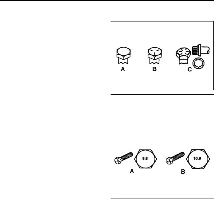
Torque Specifications |
Fastener Identification |
Recommended fastener torque values are listed in the following tables. For critical applications, as determined by Toro, either the recommended torque or a torque that is unique to the application is clearly identified and specified in the service manual.
These torque specifications for the installation and tightening of fasteners shall apply to all fasteners which do not have a specific requirement identified in the service manual. The following factors shall be consid ered when applying torque: cleanliness of the fastener, use of a thread sealant (Loctite), degree of lubrication on the fastener, presence of a prevailing torque feature, hardness of the surface underneath of the fastener’s head, or similar condition which affects the installation.
As noted in the following tables, torque values should be reduced by 25% for lubricated fasteners to achieve the similar stress as a dry fastener. Torque values may also have to be reduced when the fastener is threaded into aluminum or brass. The specific torque value should be determined based on the aluminum or brass material strength, fastener size, length of thread engagement, etc.
The standard method of verifying torque shall be per formed by marking a line on the fastener (head or nut) and mating part, then back off fastener 1/4 of a turn.
Measure the torque required to tighten the fastener until the lines match up.
Inch Series bolts and Screws
(A) Grade 1 & 2 |
(C) Grade 8 |
|
(B) Grade 5 |
|
|
|
|
|
|
|
|
Metric Bolts and Screws
(A) Class 8.8 |
(B) Class 10.9 |
Toro Wheeled CUL Service Manual |
2/1-7 |

SPECIFICATIONS
Standard Torque forr Dry,, Zinc Plated,t |
and Steel Fasteners (Inch Series) |
|
|
|||||||||||||||
|
|
|
|
|
|
|
|
|||||||||||
|
Grade 1, 5, & |
SAE Grade 1 Bolts, Screws, |
SAE Grade 5 Bolts, Screws, |
SAE Grade 8 Bolts, Screws, |
||||||||||||||
Thread Size |
8 with Thin |
Studs, & Sems with Regular |
Studs, & Sems with Regular |
Studs, & Sems with Regular |
||||||||||||||
Height Nuts |
Height Nuts (SAE J995 |
Height Nuts (SAE J995 |
Height Nuts (SAE J995 |
|||||||||||||||
|
||||||||||||||||||
|
|
|
Grade 2 or Stronger Nuts) |
Grade 2 or Stronger Nuts) |
Grade 2 or Stronger Nuts) |
|||||||||||||
|
|
|
|
|
|
|
|
|
|
|
|
|
|
|
|
|
|
|
|
In-lb |
|
In-lb |
|
N-cm |
|
In-lb |
|
|
N-cm |
|
|
In-lb |
|
N-cm |
|
|
|
|
|
|
|
|
|
|
|
|
|
|
|
|
|
|
|
|
|
|
# 6 - 32 UNC |
10 |
± 2 |
13 |
± 2 |
147 |
± 23 |
15 |
± |
2 |
170 |
± |
20 |
23 |
± 2 |
260 |
± |
20 |
|
# 6 - 40 UNF |
17 |
± |
2 |
190 |
± |
20 |
25 |
± 2 |
280 |
± |
20 |
|||||||
|
|
|
|
|
|
|||||||||||||
# 8 - 32 UNC |
13 |
± 2 |
25 |
± 5 |
282 |
± 30 |
29 |
± |
3 |
330 |
± |
30 |
41 |
± 4 |
460 |
± |
45 |
|
# 8 - 36 UNF |
31 ± 3 |
350 ± 30 |
43 |
± 4 |
31 ± 3 |
|||||||||||||
|
|
|
|
|
|
|||||||||||||
# 10 - 24 UNC |
18 |
± 2 |
30 |
± 5 |
339 |
± 56 |
42 |
± 4 |
475 |
± |
45 |
60 |
± 6 |
674 |
± 70 |
|||
#10 - 32 UNF |
48 |
± 4 |
540 |
± |
45 |
68 |
± 6 |
765 |
± 70 |
|||||||||
|
|
|
|
|
|
|||||||||||||
1/4 - 20 UNC |
48 |
± 7 |
53 |
± 7 |
599 |
± 79 |
100 |
± 10 |
1125 ± 100 |
140 |
± 15 |
1580 |
± 170 |
|||||
1/4 - 28 UNF |
53 |
± 7 |
65 ± 10 |
734 ± 113 |
115 ± 10 |
1300 |
± |
100 |
160 |
± 15 |
1800 |
± 170 |
||||||
5/16 - 18 UNC |
115 ± 15 |
105 |
± 17 |
1186 ± 169 |
200 |
± 25 |
2250 |
± |
280 |
300 |
± 30 |
3390 |
± 340 |
|||||
5/16 - 24 UNF |
138 |
± 17 |
128 |
± 17 |
1446 |
± 192 |
225 |
± 25 |
2540 |
± |
280 |
325 |
± 30 |
3670 |
± 340 |
|||
|
ft-lb |
ft-lb |
N-m |
ft-lb |
N-m |
ft-lb |
N-m |
|||||||||||
3/8 - 16 UNC |
16 |
± 2 |
16 |
± 2 |
22 |
± 3 |
30 |
± 3 |
41 |
± |
4 |
43 |
± 4 |
58 |
± 5 |
|||
3/8 - 24 UNF |
17 |
± 2 |
18 |
± 2 |
24 |
± 3 |
35 |
± 3 |
47 |
± |
4 |
50 |
± 4 |
68 |
± 5 |
|||
7/16 - 14 UNC |
27 |
± 3 |
27 |
± 3 |
37 |
± 4 |
50 |
± 5 |
68 |
± |
7 |
70 |
± 7 |
68 |
± 9 |
|||
7/16 - 20 UNF |
29 |
± 3 |
29 |
± 3 |
39 |
± 4 |
55 |
± 5 |
75 |
± |
7 |
77 |
± 7 |
104 ± 9 |
||||
1/2 - 13 UNC |
30 |
± 3 |
48 |
± 7 |
65 |
± 9 |
75 |
± 8 |
102 ± 11 |
105 |
± 10 |
142 |
± 14 |
|||||
1/2 - 20 UNF |
32 |
± 3 |
53 |
± 7 |
72 |
± 9 |
85 |
± 8 |
115 |
± |
11 |
120 |
± 10 |
163 |
± 14 |
|||
5/8 - 11 UNC |
65 ± 10 |
88 ± 12 |
119 ± 16 |
150 |
± 15 |
203 |
± |
20 |
210 |
± 20 |
285 |
± 27 |
||||||
5/8 - 18 UNF |
75 ± 10 |
95 ± 15 |
129 |
± 20 |
170 |
± 15 |
230 |
± |
20 |
240 |
± 20 |
325 |
± 27 |
|||||
3/4 - 10 UNC |
93 ± 12 |
140 |
± 20 |
190 |
± 27 |
265 |
± 25 |
359 |
± |
34 |
374 |
± 35 |
508 |
± 47 |
||||
3/4 - 16 UNF |
115 ± 15 |
165 |
± 25 |
224 |
± 34 |
300 |
± 25 |
407 |
± |
34 |
420 |
± 35 |
569 |
± 47 |
||||
7/8 - 9 UNC |
140 |
± 20 |
225 |
± 25 |
305 |
± 34 |
430 |
± 45 |
583 |
± |
61 |
600 |
± 60 |
813 |
± 81 |
|||
7/8 - 14 UNF |
155 |
± 25 |
260 |
± 30 |
353 |
± 41 |
475 |
± 45 |
644 |
± |
61 |
660 |
± 60 |
895 |
± 81 |
|||
|
|
|
|
|
|
|
|
|
|
|
|
|
|
|
|
|
|
|
Note: Reduce torque values listed in the table above by 25% for lubricated fasteners. Lubricated fasteners are defined as threads coated with a lubricant such as oil, graphite, or thread sealant such as Loctite.
Note: Torque values may have to be reduced when installing fasteners into threaded aluminum or brass. The specific torque value should be determined based on the fastener size, the aluminum or base material strength, length of thread engagement, etc.
Note: The nominal torque values listed above for Grade 5 and 8 fasteners are based on 75% of the minimum proof load specified in SAE J429. The tolerance is approximately ± 10% of the nominal torque value. Thin height nuts include jam nuts.
2/1-8 |
Toro Wheeled CUL Service Manual |

SPECIFICATIONS
Standard Torque for Dry, Zinc and Steel Fasteners (Metric Series)
Standard Torque for Dry, Zinc, and Steel Fasteners (Metric Fasteners)
Thread Size |
Class 8.8 Bolts, Screws, and Studs with |
Class 10.9 Bolts, Screws, and Studs with |
||||||||
|
Regular Height Nuts |
|
Regular Height Nuts ( |
|
||||||
|
|
(Class 8 or Strong Nuts) |
|
Class 10 or Strong Nuts) |
||||||
M5 X 0.8 |
57 ± 5 in-lb |
640 |
± 60 N-cm |
78 ± 7 in-lb |
885 ± 80 N-cm |
|||||
M6 X 1.0 |
96 ± 9 in-lb |
1018 |
± 100 N-cm |
133 ± 13 in-lb |
1500 ± 150 N-cm |
|||||
M8 X 1.25 |
19 |
± 2 ft-lb |
26 |
± 3 N-m |
27 |
± 2 ft-lb |
36 |
± |
3 N-m |
|
M10 X 1.5 |
38 |
± 4 ft-lb |
52 |
± 5 N-m |
53 |
± 5 ft-lb |
72 |
± |
7 N-m |
|
M12 X 1.75 |
66 |
± 7 ft-lb |
90 |
± 10 N-m |
92 |
± 9 ft-lb |
125 |
± |
12 N-m |
|
M16 X 2.0 |
166 |
± 15 ft-lb |
225 |
± 20 N-m |
229 |
± 22 ft-lb |
310 |
± |
30 N-m |
|
M20 X 2.5 |
325 |
± 33 ft-lb |
440 |
± 45 N-m |
450 |
± 37 ft-lb |
610 |
± |
50 N-m |
|
|
|
|
|
|
|
|
|
|
|
|
Note: Reduce torque values listed in the table above by 25% for lubricated fasteners. Lubricated fasteners are defined as threads coated with a lubricant such as oil, graphite, or thread sealant such as Loctite.
Note: Torque values may have to be reduced when installing fasteners into threaded aluminum or brass. The specific torque value should be determined based on the fastener size, the aluminum or base material strength, length of thread engagement, etc.
Note: The nominal torque values listed above are based on 75% of the minimum proof load specified in SAE J1199. The tolerance is approximately ± 10% of the nominal torque value. Thin height nuts include jam nuts.
Toro Wheeled CUL Service Manual |
2/1-9 |
SPECIFICATIONS
OtherTorqueSpecifications
SAE Grade 8 Steel Set Screws
Thread Size |
Recommended Torque |
||
|
|
||
Square Head |
Hex Socket |
||
|
|||
|
|
|
|
1/4 - 20 UNC |
140 ± 20 in-lb |
73 ± 12 in-lb |
|
|
|
|
|
5/16 - 18 UNC |
215 ± 35 in-lb |
145 ± 20 in-lb |
|
|
|
|
|
3/8 - 16 UNC |
35 ± 10 ft-lb |
18 ± 3 ft-lb |
|
|
|
|
|
1/2 - 13 UNC |
75 ± 15 ft-lb |
50 ± 10 ft-lb |
|
|
|
|
|
Wheel Bolts and Lug Nuts
Thread Size |
Recommended Torque** |
||
|
|
|
|
7/16 - 20 UNF |
65 ± 10 ft-lb |
88 ± 14 N-m |
|
Grade 5 |
|||
|
|
||
|
|
|
|
1/2 - 20 UNF |
80 ± 10 ft-lb |
108 ± 14 N-m |
|
Grade 5 |
|||
|
|
||
|
|
|
|
M12 X 1.25 |
80 ± 10 ft-lb |
108 ± 14 N-m |
|
Class 8.8 |
|||
|
|
||
|
|
|
|
M12 X 1.5 |
80 ± 10 ft-lb |
108 ± 14 N-m |
|
Class 8.8 |
|||
|
|
||
** For steel wheels and non-lubricated fasteners.
Thread Cutting Screws |
Thread Cutting Screws |
(Zinc Plated Steel) |
(Zinc Plated Steel) |
Type 1, Type 23, or Type F
Thread Size |
Baseline Torque* |
|
|
|
|
No. 6 - 32 UNC |
20 |
± 5 in-lb |
|
|
|
No. 8 - 32 UNC |
30 |
± 5 in-lb |
|
|
|
No.10 - 24 UNC |
38 |
± 7 in-lb |
|
|
|
1/4 - 20 UNC |
85 ± 15 in-lb |
|
|
|
|
5/16 - 18 UNC |
110 |
± 20 in-lb |
|
|
|
3/8 - 16 UNC |
200 ± 100 in-lb |
|
|
|
|
Thread |
Threads per Inch |
Baseline Torque* |
||
|
|
|||
Size |
Type A |
Type B |
||
|
||||
|
|
|||
No. 6 |
18 |
20 |
20 ± 5 in-lb |
|
No. 8 |
15 |
18 |
30 ± 5 in-lb |
|
No. 10 |
12 |
16 |
38 ± 7 in-lb |
|
No. 12 |
11 |
14 |
85 ± 15 in-lb |
|
* Hole size, material strength, material thickness and finish must be considered when determining specific torque values. All torque values are based on nonlubricated fasteners.
Conversion Factors |
|
in-lb X 11.2985 - N-cm |
N-cm X - 0.08851 = in-lb |
ft-lb X 1.3558 = N-m |
N-cm X 0.73776 - ft-lb |
2/1-10 |
Toro Wheeled CUL Service Manual |

SPECIFICATIONS
Equivalents andConversions
and
Decimal and Millimeter Equivalents
Fractions |
Decimals |
mm |
Fractions |
|
Decimals |
mm |
1/64 |
0.015625 |
0.397 |
|
33/64 |
0.515625 |
13.097 |
1/32 |
0.03125 |
0.794 |
16/32 |
|
0.53125 |
13.484 |
3/64 |
0.046875 |
1.191 |
|
35/64 |
0.546875 |
13.891 |
1/16 |
0.0625 |
1.588 |
9/16 |
|
0.5625 |
14.288 |
5/64 |
0.078125 |
1.984 |
|
37/64 |
0.578125 |
14.684 |
3/32 |
0.9375 |
2.381 |
19/32 |
|
0.59375 |
15.081 |
1/8 |
0.1250 |
3.175 |
5/8 |
|
0.6250 |
15.875 |
9/64 |
0.140625 |
3.572 |
|
41/64 |
0.640625 |
16.272 |
5/32 |
0.15625 |
3.969 |
21/32 |
|
0.65625 |
16.669 |
11/64 |
0.171875 |
4.366 |
|
43/64 |
0.671875 |
17.066 |
3/16 |
0.1875 |
4.762 |
11/16 |
|
0.6875 |
17.462 |
13/64 |
0.203125 |
5.159 |
|
45/64 |
0.703125 |
17.859 |
7/32 |
0.21875 |
5.556 |
23/32 |
|
0.71875 |
18.256 |
15/64 |
0.234375 |
5.953 |
|
47/64 |
0.734375 |
18.653 |
1/4 |
0.2500 |
6.350 |
3/4 |
|
0.7500 |
19.050 |
17/64 |
0.265625 |
6.747 |
|
49/64 |
0.765625 |
19.447 |
9/32 |
0.28125 |
7.144 |
25/32 |
|
0.78125 |
19.844 |
19/64 |
0.296875 |
7.541 |
|
51/64 |
0.796875 |
20.241 |
5/16 |
0.3125 |
7.541 |
13/16 |
|
0.8125 |
20.638 |
21/64 |
0.328125 |
8.334 |
|
53/64 |
0.828125 |
21.034 |
11/32 |
0.34375 |
8.731 |
27/32 |
|
0.84375 |
21.431 |
23/64 |
0.359375 |
9.128 |
|
55/64 |
0.859375 |
21.828 |
3/8 |
0.3750 |
9.525 |
7/8 |
|
0.8750 |
22.225 |
25/64 |
0.390625 |
9.922 |
|
57/64 |
0.890625 |
22.622 |
13/32 |
0.40625 |
10.319 |
29/32 |
|
0.90625 |
23.019 |
27/64 |
0.421875 |
10.716 |
|
59/64 |
0.921875 |
23.416 |
7/16 |
0.4375 |
11.112 |
15/16 |
|
0.9375 |
23.812 |
29/64 |
0.453125 |
11.509 |
|
61/64 |
0.953125 |
24.209 |
15/32 |
0.46875 |
11.906 |
31/32 |
|
0.96875 |
24.606 |
31/64 |
0.484375 |
12.303 |
|
63/64 |
0.984375 |
25.003 |
1/2 |
0.5000 |
12.700 |
1 |
|
1.000 |
25.400 |
1 mm = 0.03937 in. |
|
|
0.001 in. = 0.0254 mm |
|
||
Toro Wheeled CUL Service Manual |
2/1-11 |

SPECIFICATIONS
|
U.S. to |
|
|
|
|
U.S. toMetric Conversions |
|
|
|
|
To Convert |
Into |
Multiply By |
|
|
|
|
|
|
|
|
|
|
|
|
Miles |
Kilometers |
|
1.609 |
|
Yards |
Meters |
|
0.9144 |
Linear |
Feet |
Meters |
|
0.3048 |
Feet |
Centimeters |
|
30.48 |
|
Measurement |
Inches |
Meters |
|
0.0254 |
|
Inches |
Centimeters |
|
|
|
|
2.54 |
||
|
Inches |
Millimeters |
|
|
|
|
25.4 |
||
|
|
|
|
|
|
|
|
|
|
|
Square Miles |
Square Kilometers |
|
2.59 |
Area |
Square Feet |
Square Meters |
|
0.0929 |
Square Inches |
Square Centimeters |
|
6.452 |
|
|
Acre |
Hectare |
|
0.4047 |
|
|
|
|
|
|
Cubic Yards |
Cubic Meters |
|
0.7646 |
Volume |
Cubic Feet |
Cubic Meters |
|
0.02832 |
|
Cubic Inches |
Cubic Centimeters |
|
16.39 |
|
|
|
|
|
|
Tons (Short) |
Metric Tons |
|
0.9078 |
Weight |
Pounds |
Kilograms |
|
0.4536 |
|
Ounces |
Grams |
|
28.3495 |
|
|
|
|
|
Pressure |
Pounds/Sq. In. |
Kilopascal |
|
6.895 |
|
|
|
|
|
|
Foot-pounds |
Newton-Meters |
|
1.356 |
Work |
Foot-pounds |
Kilogram-Meters |
|
0.1383 |
|
Inch-pounds |
Kilogram-Centimeters |
|
1.152144 |
|
|
|
|
|
Liquid Volume |
Quarts |
Liters |
|
0.9463 |
Gallons |
Liters |
|
3.785 |
|
|
|
|||
|
|
|
|
|
Liquid Flows |
Gallons/Minute |
Liters/Minute |
|
3.785 |
|
|
|
|
|
Temperature |
Fahrenheit |
Celsius |
1. |
Subtract 32° |
|
|
2. |
Multiply by 5/9 |
|
|
|
|
||
|
|
|
|
|
2/1-12 |
Toro Wheeled CUL Service Manual |

ALL UNITS/GENERAL
Raising the Traction Unit |
5. Raise the front of the machine (Fig. 0003). |
1.Raise the loader arm 6” – 12” (15 – 30cm) off the ground.
2.Turn off the machine and remove the key.
3.Lift the rear of the machine (Fig. 0001).
Fig. 0001 |
DSC-0100a |
4.Position jackstands under the rear 2 corners of the machine. Remove the floor jack (Fig. 0002).
Fig. 0003 |
DSC-0105a |
6.Position jackstands under the front 2 corners of the machine. Remove the floor jack (Fig. 0004).
Fig. 0004 |
DSC-0107a |
7. Lower the loader arm.
Fig. 0002 |
DSC-0099a |
Toro Wheeled CUL Service Manual |
3/1-1 |
ALL UNITS/GENERAL
98-9050 Counterbalance Valve
Rebuild
1.Secure the counterbalance valve in a vise.
2.Remove both cartridges from the valve (Fig. 0005).
4.Install the two cartages into the counterbalance valve body (Fig. 0007).
Fig. 0007 |
IMG-0180a |
Fig. 0005 |
IMG-0180a |
3.Replace the o-rings and back-up rings on each of the cartridges (Fig. 0006).
A
B 

|
Fig. 0006 |
IMG-0188 |
A. O-rings (3) |
B. |
Back-up rings (3) |
3/1-2 |
Toro Wheeled CUL Service Manual |

ALL UNITS/GENERAL
99-3040 Counterbalance Valve
Rebuild
1.Secure the counterbalance valve in a vise.
2.Remove both cartridges from the valve (Fig. 0008).
Fig. 0008 |
IMG-0190a |
3. Remove the needle valve assembly (Fig. 0009).
Fig. 0009 |
IMG-0191a |
4.Replace the o-rings and back-up rings on both cartridges (Fig. 0010).
A
B 

|
Fig. 0010 |
IMG-0188a |
A. O-rings (3) |
B. |
Back-up rings (3) |
5. Replace the o-ring on the needle valve (Fig. 0011).
Fig. 0011 |
IMG-0192a |
Toro Wheeled CUL Service Manual |
3/1-3 |

ALL UNITS/GENERAL
6.Install the needle valve into the valve body (Fig. 0012).
Fig. 0012 |
IMG-0191a |
7.Install the two cartages into the valve body (Fig. 0013).
Fig. 0013 |
IMG-0190a |
3/1-4 |
Toro Wheeled CUL Service Manual |

ALL UNITS/GENERAL
99-3070 4-Spool Valve Rebuild (Diesel)
3. Remove the 4-spool return springs (Fig. 0016).
1.Remove the two neutral safety switches from the spring covers (Fig. 0014).
Fig. 0014 |
IMG-0438a |
2.Remove the 4 return spring covers from the bottom of the 4-spool valve (Fig. 0015).
Fig. 0016 |
IMG-0440a |
4.Remove the 2 switch block mounts from the 4-spool valve (Fig. 0017).
Fig. 0017 |
IMG-0442a |
Fig. 0015 |
IMG-0439a |
Toro Wheeled CUL Service Manual |
3/1-5 |

ALL UNITS/GENERAL
5.Remove the 2 detents for the neutral safety switches (Fig. 0018).
7.Remove the 4-spool valves from the valve body (Fig. 0020).
Fig. 0018 |
IMG-0443a |
Fig. 0020 |
IMG-0447a |
6.Remove the 4 operator assemblies from the spool valve (Fig. 0019). Remove the gaskets from the operator assemblies.
8.Remove the relief valve from the valve body (Fig. 0021).
Fig. 0021 |
IMG-0450a |
Fig. 0019 |
IMG-0446a |
3/1-6 |
Toro Wheeled CUL Service Manual |

ALL UNITS/GENERAL
9.Remove the 3 check valves from the valve body (Fig. 0022).
11. Remove the plug from the valve body (Fig. 0024).
Fig. 0024 |
IMG-0455a |
Fig. 0022 |
IMG-0451a |
10.Remove check valve located on the bottom of the valve body (Fig. 0023).
12.Remove the 8 o-rings from the valve ports (Fig. 0025). Check the o-rings for cuts and/or chafing. If there are signs of damage, the spools may be damaged and need replacing. Discard the o-rings after inspection.
Fig. 0023 |
IMG-0452a |
Fig. 0025 |
IMG-0456a |
13.Flush and clean the valve housing with a cleaning solvent and air dry. Inspect the valve and valve components. Replace if nicks, scratches, wear, or contamination are present.
Toro Wheeled CUL Service Manual |
3/1-7 |
Loading...