


Form No. 3413-815 Rev A
Lift Hose Kit
TX 1000 Compact Tool Carrier
Model No. 133-8590
Installation Instructions
 WARNING
CALIFORNIA
Proposition 65 Warning
This product contains a chemical or chemicals known to the State of California to cause cancer, birth defects, or reproductive harm.
Note: Determine the left and right sides of the machine from the normal operating position.
Installation
Loose Parts
Use the chart below to verify that all parts have been shipped.
Procedure |
Description |
Qty. |
Use |
|
|
|
|
|
|
1 |
No parts required |
– |
Prepare the machine. |
|
|
|
|
||
2 |
No parts required |
– |
Remove the hoses. |
|
|
|
|
||
3 |
Long trim seal |
2 |
Install the trim seals. |
|
Short trim seal |
2 |
|||
|
||||
4 |
Right hoses |
2 |
|
|
Hose sleeve |
1 |
Replacing the right hoses. |
||
Cable tie |
2 |
|
||
|
|
|||
|
Left hose |
2 |
|
|
5 |
Hose nut |
2 |
Install the left hoses. |
|
Hose sleeve |
1 |
|||
|
||||
|
Cable tie |
2 |
|
|
6 |
No parts required |
– |
Complete the installation. |
|
|
|
|
© 2017—The Toro® Company |
Register at www.Toro.com. |
Original Instructions (EN) |
*3413-815* A |
8111 Lyndale Avenue South |
|
Printed in the USA |
|
Bloomington, MN 55420 |
|
All Rights Reserved |
1
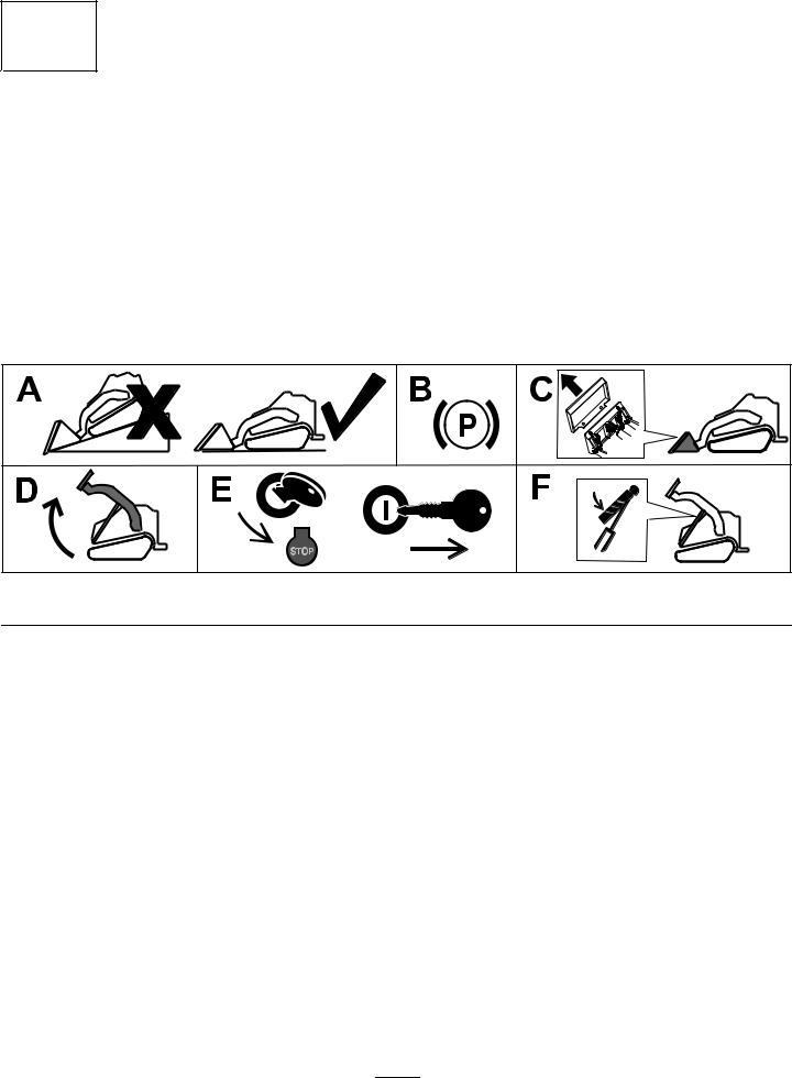
Preparing the Machine
No Parts Required
Procedure
1.Park the machine on a level surface.
2.Engage the parking brake.
3.Remove any attachments.
4.Raise the loader arms.
5.Shut off the engine and remove the key.
6.Install the cylinder locks.
g203664 |
Figure 1
2

2
Removing the Hoses
No Parts Required
Procedure
1.Cycle the loader-valve handle forward and back to relieve pressure in the hydraulic-cylinder hoses.

 WARNING
Hydraulic fluid escaping under pressure can penetrate skin and cause injury.
•If hydraulic fluid is injected into the skin, it must be surgically removed within a few hours by a doctor familiar with this type of injury. Gangrene may result if this is not done.
•Keep your body and hands away from pinhole leaks or nozzles that eject high-pressure hydraulic fluid.
•Use cardboard or paper to find hydraulic leaks.
•Safely relieve all pressure in the hydraulic system before performing any work on the hydraulic system.
•Make sure that all hydraulic-fluid hoses and lines are in good condition and all hydraulic connections and fittings are tight before applying pressure to hydraulic system.
2.Using a 9/16-inch socket, remove the 2 upper bolts (3/8 x 1 inch) from the front cover (Figure 2).
3
|
Figure 2 |
g204032 |
|
|
|
||
1. |
Upper bolt (2)—3/8 x 1 |
3. |
Washer (2) |
|
inch |
|
|
2. |
Front cover |
4. |
Lower bolt (2)—5/16 x 5/8 |
|
|
|
inch |
3.Using a 1/2-inch socket, remove the 2 lower bolts (5/16 x 5/8 inch), 2 washers, and front cover (Figure 2).
4.Place an oil container or absorbent towels under the hydraulic cylinder hoses on the right side of the machine (Figure 3).
5.Remove the outer and inner hoses using a 13/16-inch open-end wrench (Figure 3).
g203988
Figure 3
1. |
Hydraulic cylinder |
3. |
Container |
2. |
Outer hydraulic hose |
4. |
Inner hydraulic hose |
6.Drain any excess fluid from the hoses.
 Loading...