

Page 1
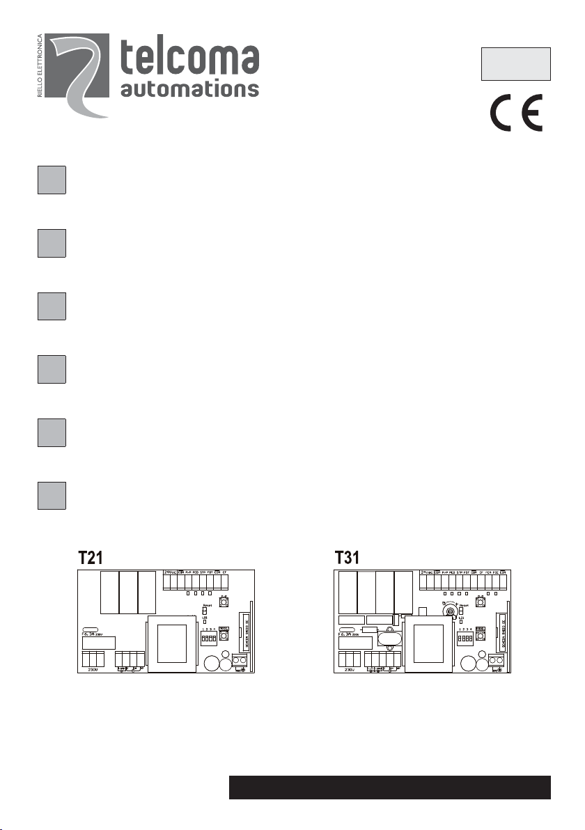
T21 - T31
ISTRUZIONI PER L’INSTALLAZIONE DELLA CENTRALINA ELETTRONICA T21 - T31 (PAG. 4)
I
IL PRESENTE LIBRETTO È DESTINATO AL PERSONALE TECNICO QUALIFICATO ALLE
INSTRUCTIONS POUR L’INSTALLATION DE LA CENTRALE ELECTRONIQUE T21 - T31 (PAG. 14)
F
CETTE NOTICE S’ADRESSE À DES TECHNICIENS SPÉCIALISÉS DANS L’INSTALLATION
INSTRUCCIONES DE LA CENTRAL ELECTRONICA T21 - T31 (PAG. 24)
E
EL PRESENTE FOLLETTO ESTÁ DESTINADO AL PERSONAL TÉCNICO ESPECIALIZADO EN INSTALACIONES
INSTRUCTIONS FOR INSTALLING THE ELECTRONIC CONTROL UNIT T21 - T31 (PAG. 34)
GB
THIS HANDBOOK IS INTENDED FOR QUALIFIED TECHNICAL INSTALLERS
INSTALLATIONSANWEISUNGEN DER ELEKTRONISCHEN STEUEREINHEIT T21 - T31 (PAG. 44)
D
DAS VORLIEGENDE HANDBUCH IST FÜR DAS MIT DER INSTALLATION BETRAUTE TECHNISCH
QUALIFIZIERTE FACHPERSONAL BESTIMMT
INSTALLAZIONI
ISTT21
V.09.2008
AANWIJZINGEN VOOR DE INSTALLATIE VAN DE ELEKTRONISCHE BESTURINGSKAST T21 - T31 (PAG. 54)
NL
DEZE HANDLEIDING IS BESTEMD VOOR VAKBEKWAME INSTALLATEURS
Telcoma srl - Via L. Manzoni, 11 - Z.I. Campidui - 31015 Conegliano - (TV) Italy
Tel. +39 0438451099 - Fax +39 0438451102 - Part. IVA 00809520265
http://www.telcoma.it E-mail: info@telcoma.it
1
Page 2
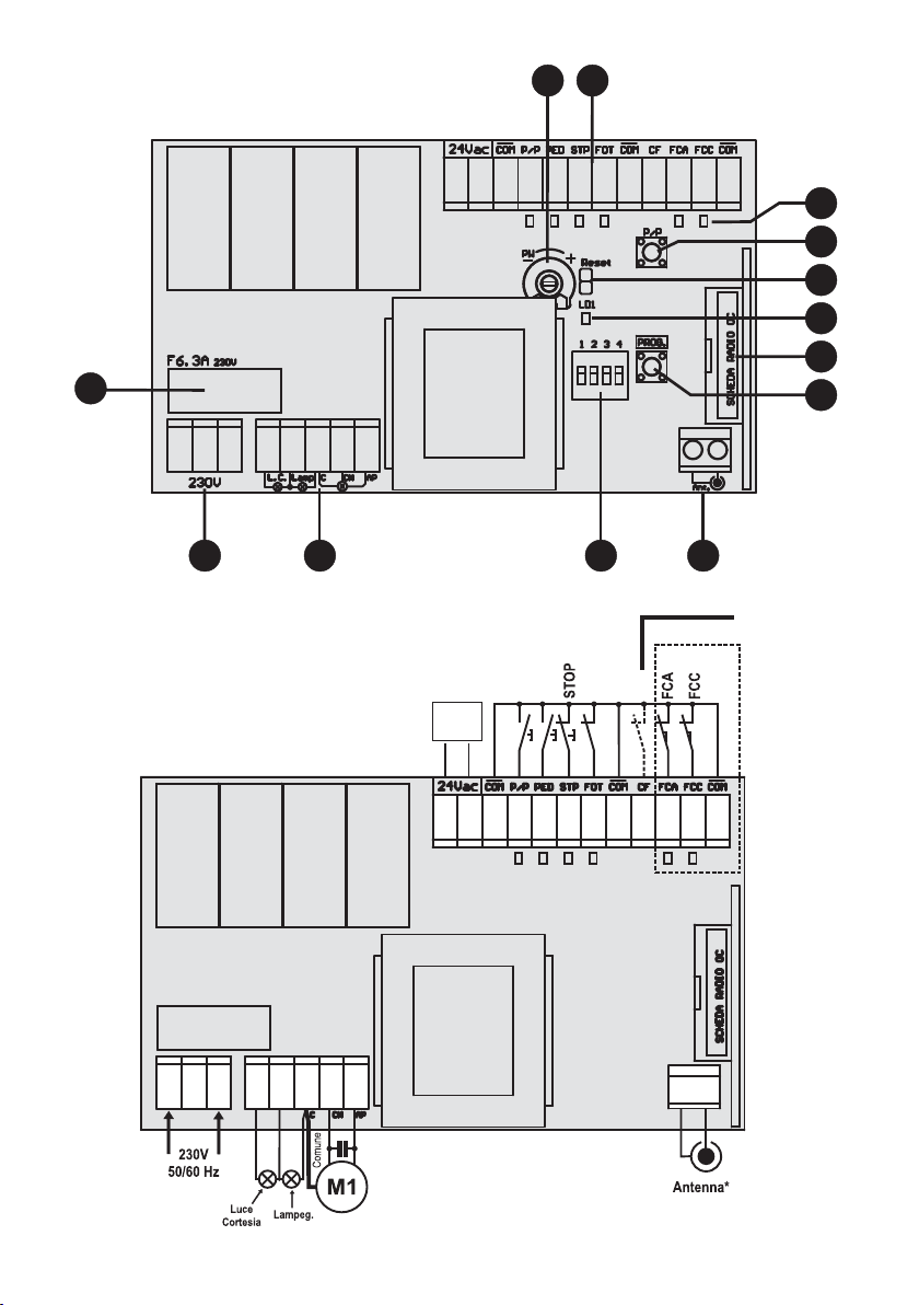
Fig.1
1213
11
10
9
8
7
1
6
Fig.2
2
12
3
45
(Tab.1)
FOT
17
C.F.
(mod. T31)
20
21
8
9
PED. (CH)
Aus.
24Vac
10
5
3
230V
6
4
7
230V
P/P (AP)
11 121314 18
15 1916
2
(mod. T31)
Page 3
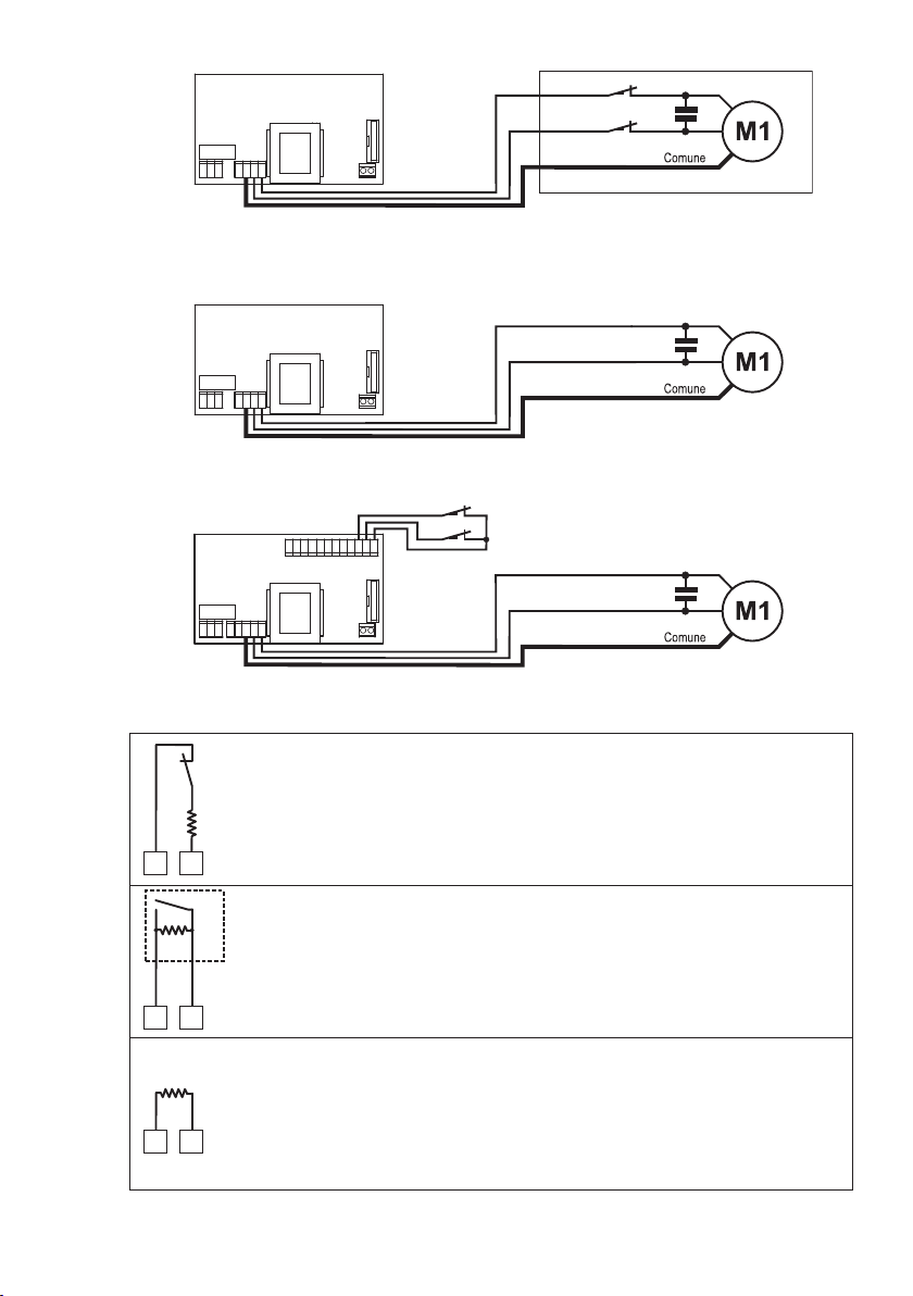
Fig.3
Fig.4
mod. T21/T31
FCA
FCC
mod. T31
Tab.1
Fig.5
COMUNECOMUNE
17
17
COMUNE
17
18
8K2
18
8K2
18
mod. T31
Collegamento di coste con contatto Normalmente Chiuso
C.F.
Connexion de barres palpeuses avec contact Normalement Fermé
N.C.
Conexión de bandas sensibles con contacto Normalmente Cerrado
Edge connection with Normally Closed contact
8K2
FCA
FCC
Anschluss von Schaltleisten mit gewöhnlich geschlossenem Kontakt
Aansluiting van contactlijsten met contact Normaal Gesloten
Collegamento di coste con contatto Normalmente Aperto In conformità alla normativa EN 12978
C.F.
N.A.
Connexion de barres palpeuses avec contact Normalement Ouvert Conformément à la norme EN 12978
Conexión de bandas sensibles con contacto Normalmente Abierto De conformidad con la normativa EN 12978
Edge connection with Normally Open contact According to EN standard 12978
Anschluss von Schaltleisten mit gewöhnlich geöffnetem Kontakt In Konformität mit der Norm EN 12978
Aansluiting van contactlijsten met contact Normaal Open In overeenstemming met de regelgeving EN 12978
Collegamento della resistenza per escludere l’ingresso
Connexion de la résistance pour exclure l’entrée
Conexión de la resistencia para excluir la entrada
Connection of resistor for input disabling
Anschluss des Widerstandes zum Ausschließen des Eingangs
Aansluiting van de weerstand om de ingang uit te sluiten
3
Page 4

ISTRUZIONI PER L’INSTALLAZIONE E LA PROGRAMMAZIONE
I
Il presente libretto è destinato al personale tecnico qualificato alle installazioni.
Prima di eseguire l’installazione consigliamo di leggere attentamente la presente istruzione.
Un uso improprio del prodotto o un errore di collegamento potrebbe pregiudicare il corretto funzionamento
dello stesso e la sicurezza dell’utente finale.
CARATTERISTICHE T21
Questa centrale può automatizzare:
- serrande o tapparelle con finecorsa incorporati nel motore
- semplici automazioni con motore 230V
La centralina è dotata di:
- auto-apprendimento dei tempi (lavoro e pausa)
- richiusura automatica (escludibile)
- connettore per ricevitori OC
- ingressi comando Passo/Passo e Pedonale
- ingressi sicurezza Stop e Fotocellula
- ingresso costa NC o bilanciato (contatto NA e resistenza 8,2K)
- uscita 24Vac per ausiliari (protezione con PTC)
- uscita motore 230V
- uscita lampeggiante 230V
CARATTERISTICHE T31
Questa centrale può automatizzare:
- serrande o tapparelle con finecorsa incorporati nel motore
- serrande o tapparelle con finecorsa esterni
- semplici automazioni con motore 230V
La centralina ha le stesse dotazioni del mod. T21 con in più:
- regolazione della coppia del motore
- ingressi finecorsa
- uscita per luce cortesia 230V
DATI TECNICI U.M. T21 - T31
Parametri elettrici
Alimentazione Vac 230 ±10%
Frequenza Hz 50
Assorbimento stand-by (230V) mA 8/10 min/max
Assorbimento Massimo (230V) A 6,3
Potenza Max motore 230V VA 1000
Temperatura funzionamento °C -20 +60
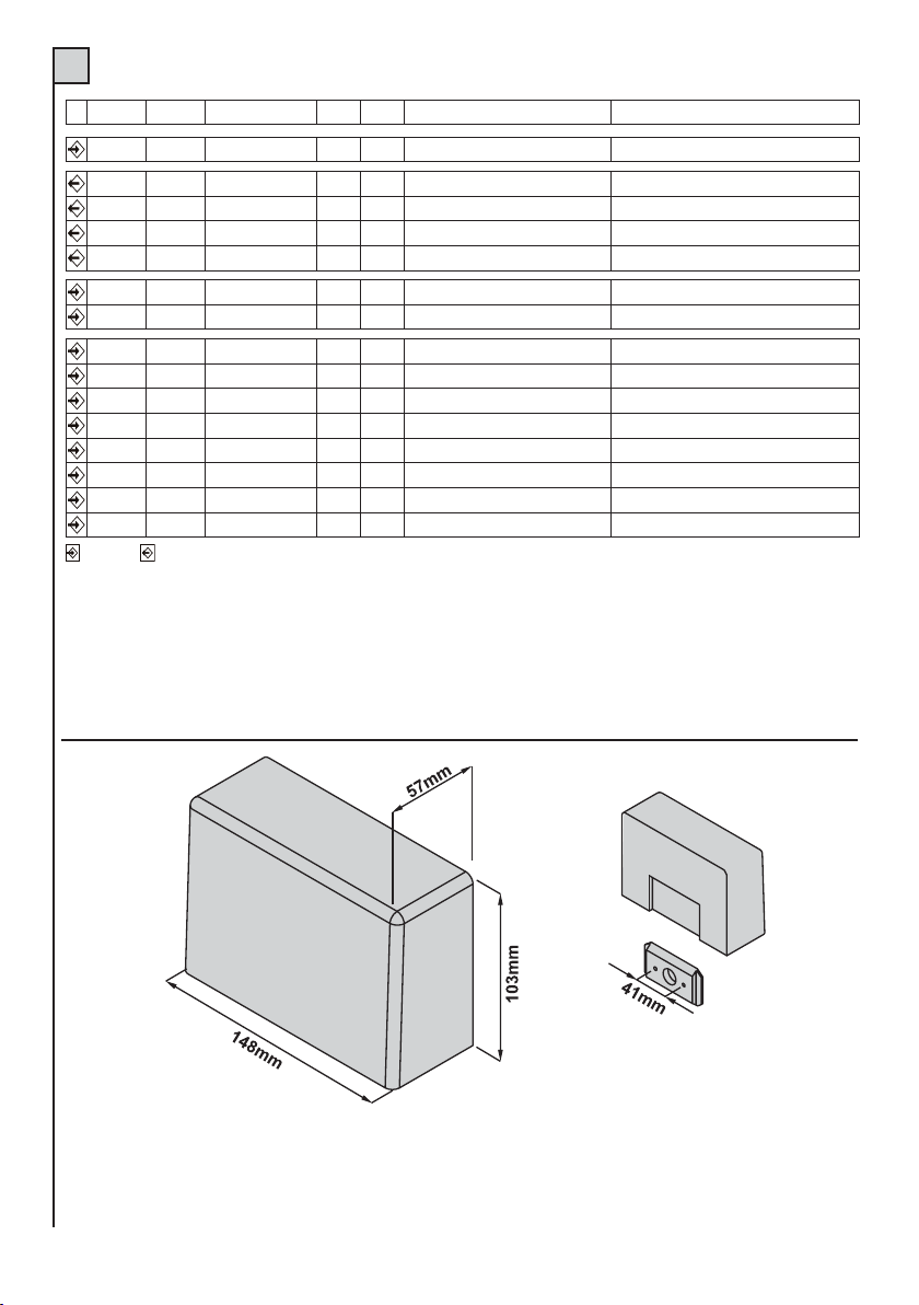
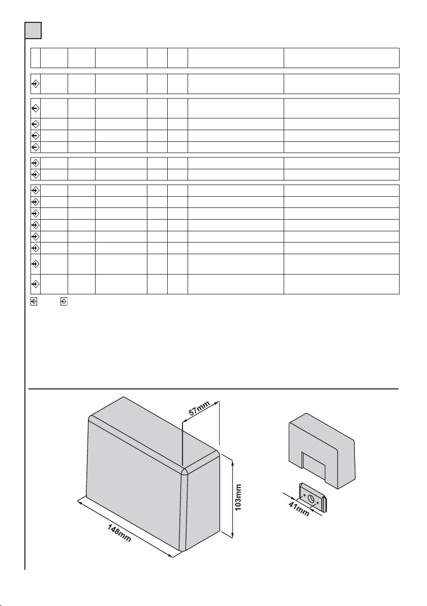
Dimensione scheda (L x H x P) mm 148x103x57
4
Page 5

DESCRIZIONE DELLE PARTI (Fig. 1)
I
1) Fusibile linea 230V 6,3A (5x20)
2) Morsettiera per collegamento linea alimentazione 230V
3) Morsettiere collegamento motore, lampeggiante e
luce cortesia (mod. T31)
4) Dip-switch funzioni
5) Morsettiera per collegamento antenna (ricevitore radio)
6) Pulsante per Programmazione e Stop*
7) Connettore per inserimento ricevitore a scheda
modello OC (optional)
* Questo pulsante di STOP non deve essere considerato di sicurezza ma solo di servizio per facilitare i test
durante l’installazione.
8) Led Programmazione (LD1)
9) Reset centralina (cortocircuitare per un attimo i 2 pin
equivale a togliere e ridare alimentazione alla centralina)
10) Pulsante Passo/Passo (P/P)
11) Led di segnalazione stato ingressi. Led acceso =
ingresso chiuso; led spento = ingresso aperto
12) Morsettiera per collegamento comandi, sicurezze e
alimentazione ausiliari
13) Trimmer per regolazione coppia motore (mod. T31)
INSTALLAZIONE
L’installazione dell’apparecchiatura deve essere effettuata a “REGOLA D’ARTE” da personale avente i requisiti
richiesti dalle leggi vigenti e seguendo
le normativeEN12453 e EN12445 riguardanti la sicurezza dell’automazione.
- Accertarsi che l’automazione sia dotata di battute di arresto e che queste siano correttamente dimensionate per
la massa del cancello.
- Fissare la centrale su una superficie piana ed immobile, adeguatamente protetta contro gli urti ed allagamenti.
COLLEGAMENTI ELETTRICI
Per i collegamenti seguire la tabella 2 e la figura 2.
Nel caso di impianti già esistenti e opportuno un controllo generale dello stato dei conduttori (sezione, isolamento,
contatti) e delle apparecchiature
ausiliarie (fotocellule, riceventi, pulsantiere, selettori chiave, ecc.).
Elenchiamo alcuni consigli per un corretto impianto elettrico:
- le condutture entranti nel box della centralina devono essere installate mantenendo possibilmente invariato
l’iniziale grado di protezione IP56.
- La sezione dei cavi deve essere calcolata in base alla loro lunghezza e corrente massima.
- Non usare un cavo unico del tipo “multi-polo” per tutti i collegamenti (linea, motori, comandi, ecc.) o in comune
con altre apparecchiature.
- Dividere l’impianto in almeno due parti, ad es.:
1) parte di potenza (linea alimentazione, motori, lampeggiante, luce cortesia, elettroserratura) sezione minima
conduttori 1.5 mm2 (linea motori 2,5 mm2).
2) parte di segnale (comandi, contatti sicurezza, alimentazione ausiliari) sezione minima conduttori 0.75mmq
- Quando i cavi di comando presentano tratte molto lunghe (oltre i 50 metri) è consigliabile il disaccoppiamento con
dei relè montati vicino alla centralina.
5
Page 6
I
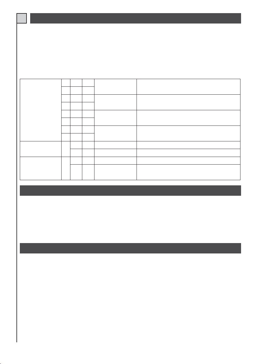
TAB. 2
Mor n. Mor n.
12Linea
34Lampada
45Lampeggiante
65Motore
75Motore
8 Antenna Rx Calza
Dispositivo V I max Funzione Note
230Vac 6,3A
230Vac 0,5A
230Vac 0,5A
230Vac 5A
230Vac 5A
Alimentazione centralina
Luce di cortesia (mod. T31)
Indicatore di movimento
Chiude
Apre
Collegare alla linea 230Vac. Vedi collegamenti elettrici.
Accesa da inizio manovra a 3 minuti dopo la chiusura completa.
Lampeggio durante la manovra. L’accensione può essere
anticipata (prelampeggio) vedi dip swich funzioni n.5.
Max 1000VA
Max 1000VA
Nel caso venga collegata una ricevente al connettore predisposto
vedere le caratteristiche dell’antenna richieste dal costruttore
9 Antenna Rx Centrale
10 11 Ausiliari
24Vac 200mA
Alimentazione
13 12,17,21 Pulsante n.a. Passo/Passo (Apre)
14 12,17,21 Pulsante n.a. Pedonale (Chiude)
15 12,17,21 Contatto n.c. Stop
16 17,12,21 Contatto n.c. Fotocellula
18 17,12,21 Contatto (tab.1) Costa in chiude
19 21,12,17 Contatto n.c. Fine-corsa Apre (mod. T31)
20 21,12,17 Contatto n.c. Fine-corsa Chiude (mod. T31)
Ingresso Uscita
Permette di alimentare fotocellule o ausiliari.
Vedi “modo ingressi Passo/Passo e Pedonale” tab.3 (dip-swich
n.1 e 2).
Vedi “modo ingressi Passo/Passo e Pedonale” tab.3 (dip-swich
n.1 e 2). Il tempo di apertura parziale è programmabile
Blocco di tutte le funzioni.
Collegare questo ingresso al comune se non viene utilizzato.
Durante la chiusura inverte la marcia.
Collegare questo ingresso al comune se non viene utilizzato.
Durante la chiusura inverte la marcia. Quando NON viene
utilizzato questo ingresso inserire la resistenza da 8,2K (tab.1).
Collegare questo ingresso al comune se non viene utilizzato.
Presente solo su mod. T31
Collegare questo ingresso al comune se non viene utilizzato.
Presente solo su mod. T31
Tutti gli ingressi N.C. (normalmente chiuso) che nella centralina non vengono utilizzati devono essere
cortocircuitati con il comune.
Tutti i contatti N.C. abbinati ad uno stesso ingresso devono essere collegati in serie.
Tutti i contatti N.A. (normalmente aperto) abbinati ad uno stesso ingresso devono essere collegati in parallelo.
Per l’alimentazione della centralina è previsto L’INSERIMENTO DI UN SEZIONATORE esterno (non in dotazione)
indipendente e dimensionato secondo il carico.
6
Page 7
IMPOSTAZIONE FUNZIONI
I
Le varie opzioni descritte nella tab.3 sono selezionabili con il dip-switch funzioni (part. 4 di fig.1).
Si tenga presente che per far apprendere una variazione delle impostazioni alla centrale dobbiamo
togliere, per un istante, e ridare l’alimentazione oppure fare un RESET
TAB. 3
Funzione
Modo Ingresso
Passo/Passo
e Pedonale
Prelampeggio 3
Richiusura 4
N.
OFF ON Descrizione Note
Dip
1
•
2
•
1
2
•
1
•
2
1
2
•
•
Apre - Stop - Chiude
•
Apre - Chiude
Apre
Funzione condominiale
•
P/P = Apre
•
PED = Chiude
•
Escluso
Inserito
•
Escluso
Inserito
•
Durante l’apertura premendo il pulsante P/P il cancello si blocca,
premendo nuovamente chiude. Durante la chiusura premendo il pulsante
P/P il cancello si blocca, premendo nuovamente apre.
Durante l’apertura premendo il pulsante P/P il cancello si blocca per pochi
secondi e poi chiude. Durante la chiusura premendo il pulsante P/P il
cancello si blocca per pochi secondi e poi apre.
Durante l’apertura premendo il pulsante P/Pn on abbiamo nessun effetto. Durante
la pausa premendo il pulsante P/P non abbiamo nessun effetto. Durante la chiusura
premendo il pulsante P/P il cancello si blocca per pochi secondi e poi apre.
L’ingresso P/Pd iventa ingresso pulsante APRE.
L’ingresso PE D diventa ingresso pulsante CHIUDE.
Il lampeggiante viene alimentato contemporaneamente con il motore.
Il lampeggiante viene alimentato 5 secondi prima di ogni manovra.
Dopo una apertura completa la centrale richiude solo con un comando
manuale.
Dopo una apertura completa la centrale richiude dopo il tempopausa
programmato.
Durante la pausa il lampeggiante fa un flash ogni 4 secondi,per avvisare
dell’imminente chiusura.
REGOLAZIONE DELLA COPPIA MOTORE (T31)
Con la centrale T31 è possibile variare la tensione erogata al motore e di conseguenza limitarne la potenza.
Questa funzione è molto importante dove vogliamo aumentare la sicurezza dell’automazione e viene fatta con il
trimmer PW (part 13 di fig.1).
La regolazione PW non viene considerata ad ogni inizio manovra dove viene data piena potenza per qualche
secondo (spunto).
NOTE SULLA PROGRAMMAZIONE DEI TEMPI DI LAVORO E PAUSA
Procedura obbligatoria in nuove installazioni, lo scopo è quello di far memorizzare alla centrale i tempi di manovra.
Durante la fase di apprendimento si azionerà più volte il tasto P/P (part. 10 di fig 1), in alternativa si può usare il comando
P/P (morsetto 13, fig. 2) oppure il trasmettitore radio memorizzato sul primo canale del ricevitore.
Note importanti prima della programmazione:
- Alimentare la centrale e verificare il corretto funzionamento degli ingressi comando tramite i relativi Led (i contatti N.C.
devono avere il Led acceso, in contatti N.A. devono avere il Led spento).
- Nel mod. T31 regolare la potenza motore a metà, tramite il trimmer PW (part. 13 di fig. 1).
- Liberare la zona di movimento del cancello.
- Eseguire l’autoapprendimento dei tempi scegliendo una delle programmazioni descritte in seguito.
7
Page 8
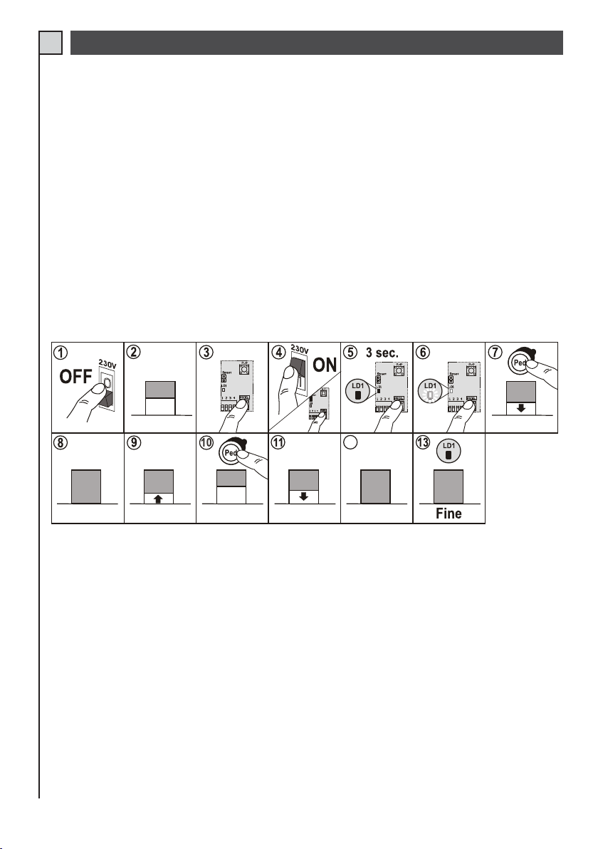
PROGRAMMAZIONE MANUALE (T21 - T31)
I
La programmazione manuale e obbligatoria nei seguenti casi:
- centrale T21 o T31 che comanda motori con finecorsa interni o collegati in serie al motore (fig.3)
- centrale T31 collegata a motori senza finecorsa (fig.4)
Nel primo caso la centrale memorizza un tempo lavoro di “sicurezza” perché l’arresto, a fine manovra, è gestito
dai finecorsa.
Nel secondo esempio l’arresto del motore viene dato al scadere del tempo memorizzato; consigliamo battute
meccaniche e una centrale (T31) con regolazione di coppia interna.
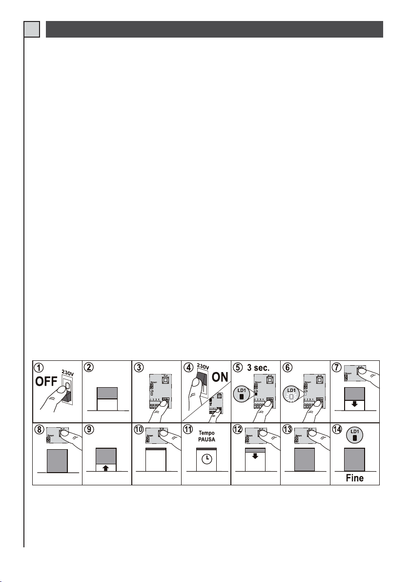
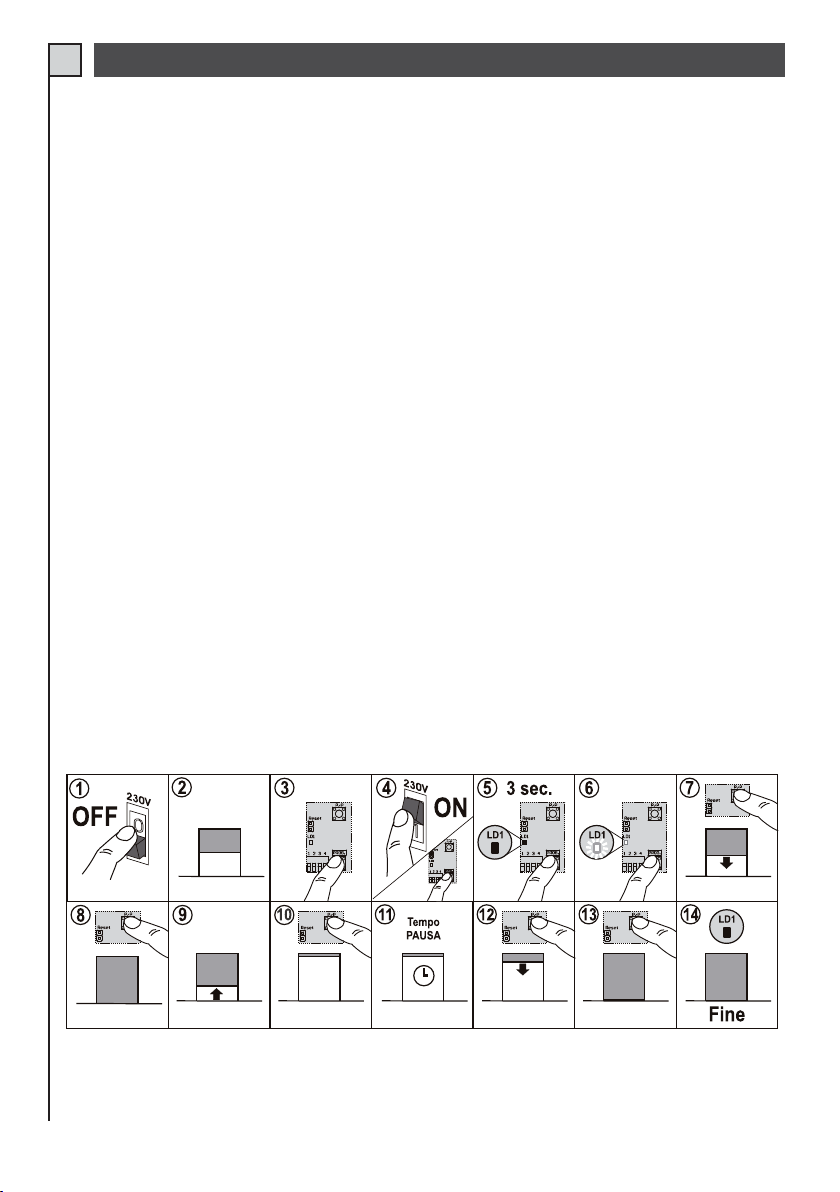
Procedura:
1 - Togliere alimentazione alla centrale.
2 - Portare la serranda a metà corsa.
3 - Premere il tasto PROG./STOP.
4,5,6 - Alimentare la centrale tenendo premuto il tasto PROG./STOP (part.6 di fig.1) per almeno 3 sec. Si accende
il led programmazione LD1. La stessa funzione può essere fatta tenendo premuto il tasto PROG./STOP,
cortocircuitando per un attimo i pin di reset (part.9 di fig.1) e rilasciando il tasto PROG./STOP quando si
accende il led LD1.
7 - Premere il pulsante P/P e la serranda deve partire in chiusura. Se parte in apertura bloccare la programmazione
invertire i fili del motore e riprendere dal punto (1).
8 - Quando la serranda è chiusa premere nuovamente P/P.
9 - Dopo una breve pausa la serranda parte in apertura.
10 - Quando è aperta completamente premere P/P.
11 - A questo punto la serranda è aperta e possiamo: o attendere il tempo di pausa desiderato o (se non usiamo la
richiusura automatica) passare direttamente al punto sucessivo.
12 - Premere il pulsante P/P per chiudere la serranda.
13 - Quando è chiusa completamente premere P/P.
14 - Il led DL1 si spegne, fine della programmazione.
TAB. 4
8
Page 9
PROGRAMMAZIONE AUTOMATICA (T31)
I
La programmazione automatica è possibile solo nel seguente caso:
- centrale T31 con finecorsa collegati direttamente alla centrale (fig.5).
Con questa configurazione non serve dare, premendo P/P, il punto di fine manovra.
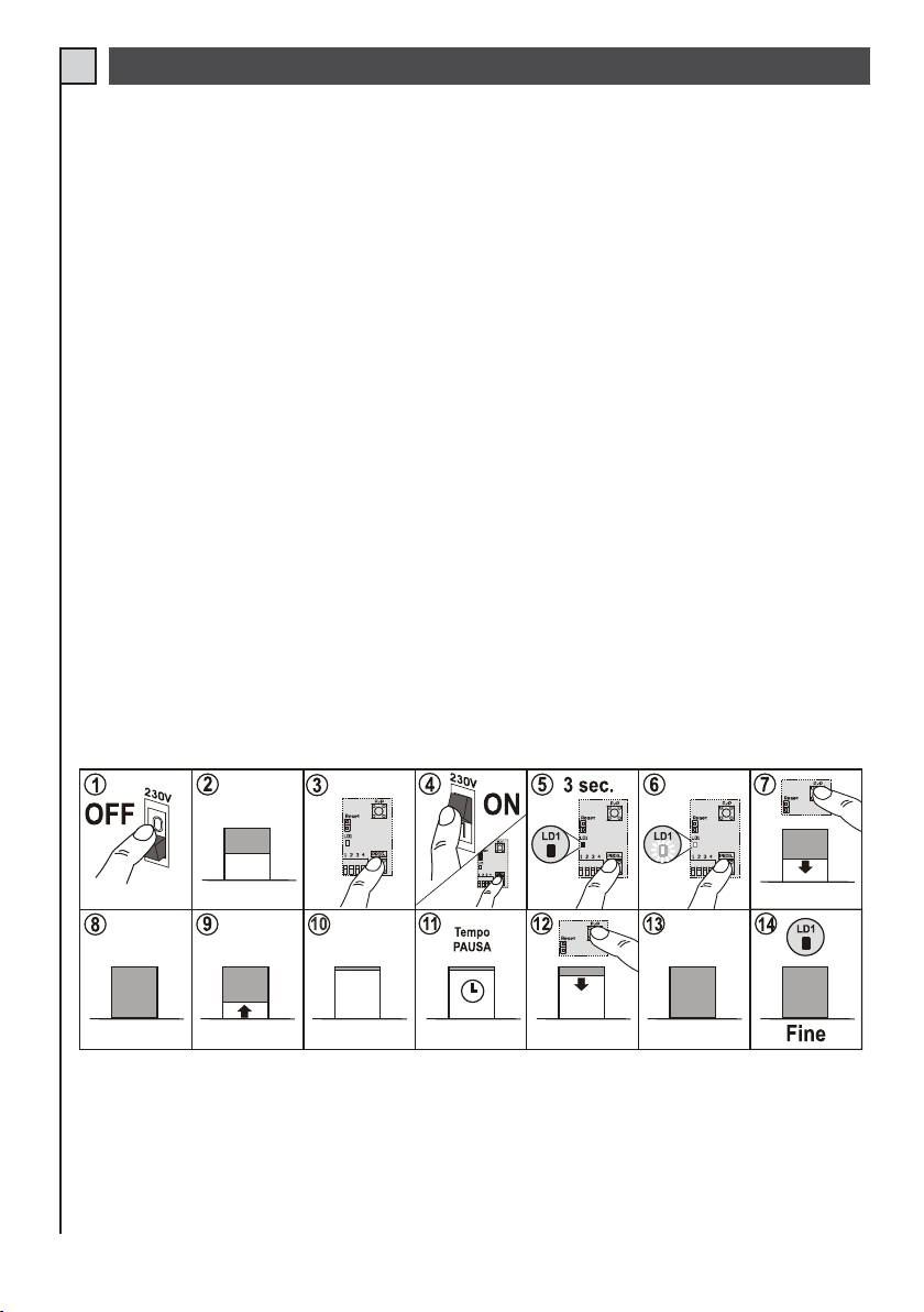
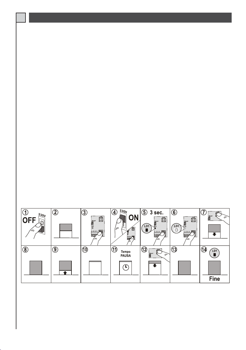
Procedura:
1 - Togliere alimentazione alla centrale.
2 - Portare la serranda a metà corsa.
3 - Premere il tasto PROG./STOP.
4,5,6 - Alimentare la centrale tenendo premuto il tasto PROG./STOP (part.6 di fig.1) per almeno 3 sec. Si accende
il led programmazione LD1. La stessa funzione può essere fatta tenendo premuto il tasto PROG./STOP,
cortocircuitando per un attimo i pin di reset (part.9 di fig.1) e rilasciando il tasto PROG./STOP quando si
accende il led LD1.
7 - Premere il pulsante P/P e la serranda deve partire in chiusura. Se parte in apertura bloccare la programmazione
invertire i fili del motore e riprendere dal punto (1).
8 - Quando la serranda arriva sul finecorsa di chiusura si ferma. Se non si ferma bloccare la programmazione e
controllare il finecorsa.
9 - Dopo una breve pausa la serranda parte in apertura.
10 - Apre completamente e si arresta quando arriva sul finecorsa di apertura. Se non si ferma bloccare la programmazione
e controllare il finecorsa.
11 - A questo punto la serranda è aperta e possiamo: o attendere il tempo di pausa desiderato o (se non usiamo la
richiusura automatica) passare direttamente al punto sucessivo.
12 - Premere il pulsante P/P per chiudere la serranda.
13 - Quando la serranda arriva sul finecorsa di chiusura si ferma.
14 - Il led DL1 si spegne, fine della programmazione.
TAB. 5
9
Page 10
PROGRAMMAZIONE DELL’APERTURA PEDONALE
I
Nelle centrali T21 e T31 è possibile programmare il tempo di apertura pedonale, abbiamo anche in questo caso due
procedure:
- MANUALE nei casi riportati in fig. 3 e 4.
- AUTOMATICA quando i finecorsa sono collegati direttamente in centrale (T31) vedi figura 5.
Per la programmazione del tempo pedonale è obbligatorio collegare un pulsante all’ingresso PED, oppure una ricevente
mod. OC2 con il secondo canale programmato.
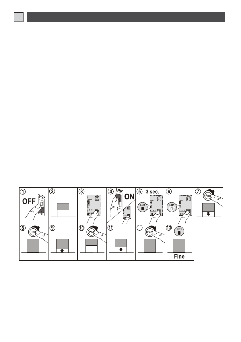
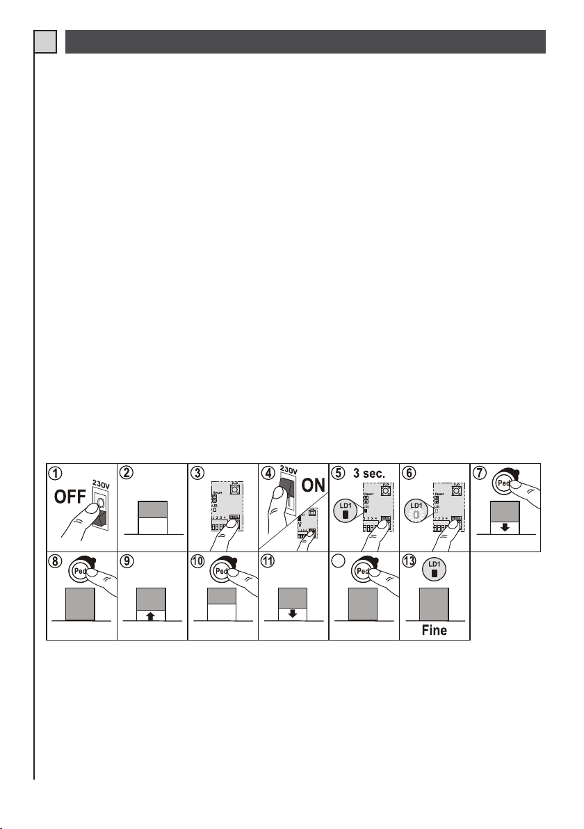
Procedura MANUALE:
1 - Togliere alimentazione alla centrale.
2 - Portare la serranda a metà corsa.
3 - Premere il tasto PROG./STOP.
4,5,6 - Alimentare la centrale tenendo premuto il tasto PROG./STOP (part.6 di fig.1) per almeno 3 sec. Si accende
il led programmazione LD1. La stessa funzione può essere fatta tenendo premuto il tasto PROG./STOP,
cortocircuitando per un attimo i pin di reset (part.9 di fig.1) e rilasciando il tasto PROG./STOP quando si
accende il led LD1.
7 - Premere il pulsante PED (o trasmettere con il secondo canale) e la serranda deve partire in chiusura.
8 - Quando la serranda è chiusa premere nuovamente PED (o trasmettere con il secondo canale).
9 - Dopo una breve pausa la serranda parte in apertura.
10 - Quando raggiungiamo l’apertura parziale desiderata premere PED (o trasmettere con il secondo canale).
11 - Dopo una breve pausa la serranda parte in chiusura.
12 - Quando è chiusa completamente premere PED (o trasmettere con il secondo canale).
13 - Il led DL1 si spegne, fine della programmazione.
TAB. 6
12
10
Page 11
Procedura AUTOMATICA:
I
1 - Togliere alimentazione alla centrale.
2 - Portare la serranda a metà corsa.
3 - Premere il tasto PROG./STOP.
4,5,6 - Alimentare la centrale tenendo premuto il tasto PROG./STOP (part.6 di fig.1) per almeno 3 sec. Si accende
il led programmazione LD1. La stessa funzione può essere fatta tenendo premuto il tasto PROG./STOP,
cortocircuitando per un attimo i pin di reset (part.9 di fig.1) e rilasciando il tasto PROG./STOP quando si
accende il led LD1.
7 - Premere il pulsante PED (o trasmettere con il secondo canale) e la serranda deve partire in chiusura.
8 - Quando la serranda arriva sul finecorsa di chiusura si ferma.
9 - Dopo una breve pausa la serranda parte in apertura.
10 - Quando raggiungiamo l’apertura parziale desiderata premere PED (o trasmettere con il secondo canale).
11 - Dopo una breve pausa la serranda parte in chiusura.
12 - Quando la serranda arriva sul finecorsa di chiusura si ferma.
13 - Il led DL1 si spegne, fine della programmazione.
TAB. 7
12
11
Page 12
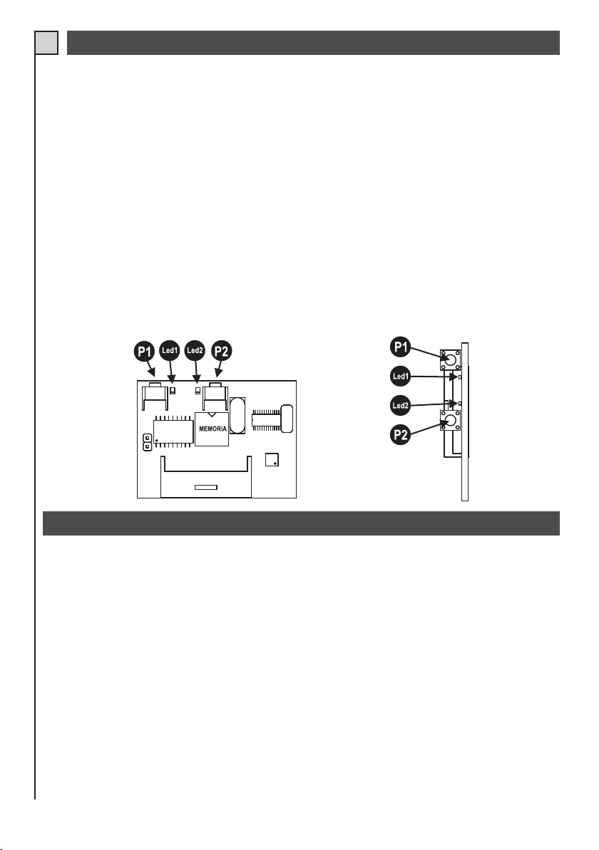
RICEVITORE AD INNESTO modello OC (opzionale)
I
Le riceventi sono ad auto-apprendimento e possono memorizzare più codici nello stesso canale.
Le funzioni dei due canali radio sono:
Canale 1 Passo/Passo
Canale 2 Pedonale
Per memorizzare i trasmettitori procedere come segue:
- Inserire la ricevente nel connettore (particolare 7 di fig. 1)
- Alimentare la centrale e attendere che i led sulla ricevente si spengano.
- Sulla ricevente premere brevemente il pulsante del canale da memorizzare, (P1 passo/passo o P2 pedonale) il led
corrispondente inizia a lampeggiare. Se il led esegue dei lampeggi doppi attendere e ripetere l’operazione (il tastino
deve essere premuto solo una volta).
- Trasmettere con il telecomando da programmare.
- Se il led sulla ricevente esegue un lampeggio più lungo vuol dire che la memorizzazione è andata a buon fine.
- Se il codice e già presente in memoria, i led della ricevente lampeggiano contemporaneamente.
È possibile resettare la memoria dei codici tenendo premuto il pulsante P1 della ricevente per circa 15 secondi sino a
quando si accendono entrambi i led.
L’antenna va collegata ai morsetti 8 (calza) e 9 (centrale) vedi fig. 2.
Per ulteriori informazioni e specifiche vedere il manuale che accompagna la ricevente.
COLLAUDO FINALE
Eseguire sempre un collaudo finale dopo aver fatto tutte le varie programmazioni.
- Controllare il corretto funzionamento dei dispositivi di protezione (sistema antischiacciamento, pulsante stop,
fotocellule, coste sensibili, ecc.)
- Controllare il corretto funzionamento del dispositivo di segnalazione (lampeggiante).
- Controllare il corretto funzionamento dei dispositivi di comando (pulsante P/P, Radiocomandi, ecc.).
12
Page 13
AVVERTENZE IMPORTANTI SULL’INSTALLAZIONE
I
L’installazione dell’automazione deve essere eseguita a regola d’arte da personale qualificato avente i requisiti di legge e
fatta in conformità della direttiva macchine 98/37/CE e alle normative EN13241-1, EN 12453 e EN 12445.
Verificare la solidità delle strutture esistenti (colonne, cerniere, ante) in relazione alle forze sviluppate dal motore.
Verificare che vi siano dei fermi meccanici di adeguata robustezza a fine apertura e fine chiusura.
Verificare lo stato di eventuali cavi già presenti nell’impianto.
Fare un’analisi dei rischi dell’automazione e di conseguenza adottare le sicurezze e le segnalazioni necessarie.
Installare i comandi (ad esempio il selettore a chiave) in modo che l’utilizzatore non si trovi in una zona pericolosa.
Terminata l’installazione provare più volte i dispositivi di sicurezza, segnalazione e di sblocco dell’automazione.
Applicare sull’automazione l’etichetta o la targhetta CE contenenti le informazioni di pericolo e i dati di identificazione.
Consegnare all’utilizzatore finale le istruzioni d’uso, le avvertenze per la sicurezza e la dichiarazione CE di conformità.
Accertarsi che l’utilizzatore abbia compreso il corretto funzionamento automatico, manuale e di emergenza
dell’automazione.
Informare l’utilizzatore per iscritto (ad esempio nelle istruzioni d’uso):
- dell’eventuale presenza di rischi residui non protetti e dell’uso improprio prevedibile.
- di scollegare l’alimentazione quando viene eseguita la pulizia nell’area dell’automazione o viene fatta piccola
manutenzione (es: ridipingere).
- di controllare frequentemente che non vi siano danni visibili all’automazione e nel caso ve ne siano, avvertire
immediatamente l’installatore
- di non far giocare i bambini nelle immediate vicinanze dell’automazione
Predisporre un piano di manutenzione dell’impianto (almeno ogni 6 mesi per le sicurezze) riportando su di un
apposito registro gli interventi eseguiti.
SMALTIMENTO
Questo prodotto è formato da vari componenti che potrebbero a loro volta contenere sostanze inquinanti.
Non disperdere nell’ambiente! Informarsi sul sistema di riciclaggio o smaltimento del prodotto attenendosi alle
norme di legge vigenti a livello locale
DICHIARAZIONE DI CONFORMITA’ CE
Il sottoscritto Augusto Silvio Brunello, il Legale Rappresentante della società:
TELCOMA S.r.l. Via Luigi Manzoni 11, 31015 Conegliano (TV) ITALY
Dichiara che il prodotto:
Modello: T21 con impiego: Centralina per apricancello
Modello: T31 con impiego: Centralina per apricancello
È conforme ai requisiti essenziali dell’articolo 3 ed ai relativi provvedimenti della Direttiva 1999/5/CE, se impiegato
per gli usi preposti.
E’ conforme ai requisiti essenziali Direttiva 89/336 (EMC) norme EN 61000-6-3, EN 61000-6-1 e
successive modifiche, se impiegato per gli usi preposti.
E’ conforme ai requisiti essenziali Direttiva 73/23 (LVD) norme EN 60335-1 e successive modifiche,
se impiegato per gli usi preposti.
Luogo e data:
Conegliano, 29/01/2007
Legale Rappresentante
Augusto Silvio Brunello
13
Page 14

INSTRUCTIONS POUR L’INSTALLATION ET LA PROGRAMMATION
F
Ce livret est destiné au personnel technique qualifié pour les installations.
Avant d’effectuer l’installation nous conseillons de lire attentivement ces instructions.
Une utilisation impropre du produit ou une erreur de connexion pourrait compromettre le fonctionnement
correct de ce dernier et la sécurité de l’utilisateur final.
CARACTÉRISTIQUES T21
Cette logique de commande peut automatiser:
- des rideaux métalliques ou des volets roulants avec fins de course incorporés au moteur
- des automatismes simples avec moteur 230V
La logique est munie de:
- auto-apprentissage des temps (travail et pause)
- refermeture automatique (excluable)
- connecteurs pour récepteurs OC
- entrées commande Pas à pas et Piétons
- entrées sécurité Stop et Photocellule
- entrée barre palpeuse NF ou équilibrée (contact NO et résistance 8,2K)
- sortie 24Vca pour auxiliaires (protection par PTC)
- sortie moteur 230V
- sortie clignotant 230V
CARACTÉRISTIQUES T31
Cette logique de commande peut automatiser :
- des rideaux métalliques ou des volets roulants avec fins de course incorporés au moteur
- des rideaux métalliques ou des volets roulants avec fins de course extérieurs
- des automatismes simples avec moteur 230V
La logique a les mêmes composants que le mod. T21 avec en plus:
- régulation du couple du moteur
- entrées fins de course
- sortie pour éclairage automatique 230V
DONNÉES TECHNIQUES U.M. T21 - T31
Paramètres électriques
Alimentation Vac 230 ±10%
Fréquence Hz 50
Absorption stand-by (230V) mA 8/10 min/max
Absorption max. (230V) A 6,3
Puissance max. moteur 230V VA 1000
Température de fonc. °C -20 +60
Dimensions carte (L x H x P) mm 148x103x57
14
Page 15

DESCRIPTION DES PARTIES (Fig. 1)
F
1 Fusible ligne 230 V 6,3 A (5x20)
2 Bornier pour connexion ligne alimentation 230 V
3 Borniers connexion moteur, clignotant et éclairage
automatique (mod. T31)
4 Dip-switch fonctions
5 Bornier pour connexion antenne (récepteur radio)
6 Bouton pour Programmation et Stop*.
7 Connecteur pour embrochage récepteur sur carte
modèle OC (option)
8 Led Programmation (LD1)
* Cette touche de STOP ne doit pas être considérée comme une sécurité mais seulement comme une touche
de service pour faciliter les tests durant l’installation.
9 Réinitialisation de la logique (court-circuiter pendant
un moment les 2 broches équivaut à couper et à
redonner l’alimentation à la logique)
10 Bouton Pas à Pas (P/P)
11 Led de signalisation d’état des entrées. Led allumée
= entrée fermée ; led éteinte = entrée ouverte
12 Bornier pour connexion des commandes, sécurités
et alimentation auxiliaires.
13 Trimmer pour régulation du couple moteur (mod.
T31)
INSTALLATION
L’installation de l’appareil doit être effectuée DANS LES RÈGLES DE L’ART par du personnel ayant les
caractéristiques requises par les lois envigueur et conformément aux normes EN 12453 et EN 12445 concernant
la sécurité de l’automatisation.
- Contrôler que l’automatisation est munie de butées d’arrêt et que celles-ci sont correctement dimensionnées
pour la masse du portail.
- Fixer la logique de commande sur une surface plane et immobile, protégée de manière adéquate contre les
chocs et les inondations.
BRANCHEMENTS ELECTRIQUES
Pour les connexions suivre le tableau 2 et la figure 2.Dans le cas d’installations pré-existantes il est opportun
d’effectuer un contrôle général de l’état des conducteurs (section, isolement, contacts) etdes appareils auxiliaires
(photocellules, récepteurs, claviers de commande, sélecteurs à clé, etc.).Voici quelques conseils pour une
installation électrique correcte:
- les canalisations entrant dans le coffret étanche de la logique de commande doivent être installées sans
compromettre si possible le degré deprotection IP56.
- La section des câbles doit être calculée suivant leur longueur et le courant maximum.
- Ne pas utiliser un câble unique du type « multipolaire » pour toutes les connexions (secteur, moteurs, commandes,
etc.) ou en commun avecd’autres appareils.
- Diviser l’installation en au moins deux parties, par ex.:
1) partie de puissance (ligne d’alimentation, moteurs, clignotant, éclairage automatique, serrure électrique) section
minimum conducteurs 1,5 mm²(ligne moteurs 2,5 mm²).
2) partie de signal (commandes, contacts de sécurité, alimentation auxiliaires) section minimum conducteurs 0,75
mm².
- Quand les câbles de commande présentent de très longs tronçons (plus de 50 mètres) il est conseillé de procéder
à un découplage avec desrelais montés près de la logique de commande.
15
Page 16
F
TAB. 2
Borne n.Borne
12Ligne
34Ampoule
45Clignotant
65Moteur
75Moteur
8 Antenne Rx Conducteur externe
Dispositif V I max Fonction Notes
n.
230Vac 6,3A
230Vac 0,5A
230Vac 0,5A
230Vac 5A
230Vac 5A
Alimentation logique de
commande
Éclairage automatique
(mod. T31)
Indicateur de mouvement
Fermeture
Ouverture
Connecter à la ligne 230 Vca. Voir branchements électriques.
Allumé du début de la manœuvre jusqu’à 3 minutes après la
fermeture complète.
Clignotement durant la manœuvre. L’allumage peut être anticipé
(préclignotement) voir dip switch fonctions n. 5.
Max. 1000 VA
Max. 1000 VA
Si un récepteur est connecté au connecteur prévu, voir les
caractéristiques de l’antenne requises par le constructeur
9 Antenne Rx Âme
10 11 Auxiliaires
24Vac 200mA
Alimentation
13 12,17,21 Touches N.O. Pas à pas (ouverture)
14 12,17,21 Touches N.O. Piéton (Fermeture)
15 12,17,21 Contact N.F. Stop
16 17,12,21 Contact N.F. Photocellule
18 17,12,21 Contact (tab.1) Barre palpeuse en fermeture
19 21,12,17 Contact N.F.
20 21,12,17 Contact N.F.
Entrée Sortie
Fin de course ouverture
(mod. T31)
Fin de course fermeture
(mod. T31)
Permet d’alimenter des photocellules ou auxiliaires.
Voir «mode entrées Pas à pas et Piéton» tab. 3 (dip-switch 1 et
2).
Voir « mode entrées Pas à pas et Piéton » tab. 3 (dip-switch 1 et
2). Le temps d’ouverture partielle est programmable
Blocage de toutes les fonctions.
Connecter cette entrée au commun si elle n’est pas utilisée.
Durant la fermeture inversion du mouvement. Connecter cette
entrée au commun si elle n’est pas utilisée.
Durant la fermeture inversion du mouvement. Quand cette entrée
N’EST PAS utilisée, brancher la résistance de 8,2K (tab.1).
Connecter cette entrée au commun si elle n’est pas utilisée.
Présente seulement sur mod. T31
Connecter cette entrée au commun si elle n’est pas utilisée.
Présente seulement sur mod. T31
Toutes les entrées N.F. (normalement fermé) qui ne sont pas utilisées dans la logique de commande doivent être
court-circuitées avecle commun.
Tous les contacts N.F. associés à une même entrée doivent être connectés en série.
Tous les contacts N.O.(normalement ouvert) associés à une même entrée doivent être connectés en parallèle.
Pour l’alimentation de la logique, on prévoit le MONTAGE D’UN SECTIONNEUR extérieur (non fourni) indépendant
et dimensionnésuivant la charge.
16
Page 17
PARAMÉTRAGE FONCTIONS
F
Les diverses options décrites dans la tab.3 sont sélectionnables avec le dip-switch fonctions (pos. 4 fig. 1)
Tenir compte que pour faire apprendre une variation des paramétrages à la logique nous devons couper,
pendant un instant, et redonner l’alimentation ou réinitialiser.
TAB. 3
Fonction
Mode Entrée
Pas à pas et
Piéton
Préclignotement 3
Refermeture 4
N.
OFF ON Description Notes
Dip
1
•
2
•
1
2
•
1
•
2
1
2
•
•
Ouverture-StopFermeture
Ouverture-
•
Fermeture
Ouverture
Fonctionnement collectif
•
P/P=Ouverture
•
PED=Fermeture
•
Exclu
Activè
•
Exclu
Activè
•
Durant l’ouverture en pressant la touche P/P le portail se bloque, en
pressant de nouveau le portail se ferme. Durant la fermeture il se bloque,
en pressant de nouveau il s’ouvre.
Durant l’ouverture en pressant la touche P/P le portail se bloque pendant
quelques secondes puis se ferme. Durant la fermeture en pressant la
touche P/P le portail se bloque pendant quelques secondes puis s’ouvre.
Durant l’ouverture la pression de la touche P/P n’a aucun effet. Durant la fermeture
en pressant la touche P/P le portail se bloque pendant quelques secondes puis
s’ouvre.
L’entrée P/P devient entrée touche OUVERTURE.
L’entrée PED devient entrée touche FERMETURE.
Le clignotant est alimenté en même temps que le moteur.
Le clignotant est alimenté 5 secondes avant chaque manœuvre.
Après une ouverture complète la logique de commande referme
uniquement avec une commande manuelle.
Après une ouverture complète la logique de commande referme après le
temps de pause programmé.
Durant la pausa, le clignotant fait un flash toute les 4 secondes pour
avertir de la fermeture imminente.
RÉGULATION DU COUPLE DU MOTEUR (T31)
Avec la logique de commande T31, il est possible de modifier la tension fournie au moteur et par conséquent d’en
limiter la puissance.
Cette fonction est très importante quand on veut augmenter la sécurité de l’automatisme et elle est activée par le
trimmer PW (pos. 13 fig.1).
La régulation PW n’est pas prise en compte à chaque début de manœuvre quand on donne pleine puissance
pendant quelques secondes (couple de démarrage).
NOTES SUR LA PROGRAMMATION DES TEMPS DE TRAVAIL ET DE PAUSE
Procédure obligatoire dans de nouvelles installations, le but est de faire mémoriser à la logique de commande les temps
de manœuvre.
Durant la phase d’apprentissage, on actionnera plusieurs fois la touche P/P (pos. 10 fig. 1), en alternative on peut utiliser
la commande P/P (borne 13, fig. 2) ou l’émetteur radio mémorisé sur le premier canal du récepteur.
Notes importantes avant la programmation:
- Alimenter la logique de commande et vérifier le fonctionnement correct des entrées de commande avec les leds
correspondantes (les contacts N.F. doivent avoir la led allumée, dans les contacts N.O. doivent avoir la led éteinte).
- Dans le mod. T31 régler la puissance moteur à moitié, à l’aide du trimmer PW (pos. 13 fig. 1).
- Libérer la zone de mouvement du portail.
- Effectuer l’auto-apprentissage des temps en choisissant l’une des programmations décrites ci-après.
17
Page 18
PROGRAMMATION MANUELLE (T21 - T31)
F
La programmation manuelle et obligatoire dans les cas suivants:
- logique de commande T21 ou T31 pour la commande de moteurs avec fins de course internes ou connectés en
série au moteur (fig. 3)
- logique de commande T31 connectée à des moteurs sans fins de course (fig.4)
Dans le premier cas, la logique de commande mémorise un temps de travail de « sécurité » parce que l’arrêt, en
fin de manœuvre, est géré par les fins de course.
Dans le deuxième exemple, l’arrêt du moteur est donné quand le temps mémorisé est écoulé ; nous conseillons des
butées mécaniques et une logique de commande (T31) avec régulation de couple interne.
Procédure:
1 - Couper l’alimentation de la logique.
2 - Porter le rideau métallique à mi-course.
3 - Presser la touche PROG./STOP.
4,5,6 - Alimenter la logique de commande en maintenant la pression sur la touche PROG./STOP (pos. 6 - fig.1)
pendant au moins 3 s. La led programmation LD1 s’allume. On obtient la même fonction en gardant la touche
PROG./STOP enfoncée, en court-circuitant un instant les broches de réinitialisation (pos. 9 - fig. 1) et en relâchant
la touche PROG./STOP quand la led LD1 s’allume.
7 - Presser la touche P/P et le rideau métallique doit partir en fermeture. S’il part en ouverture, bloquer la programmation
inverser les fils du moteur et reprendre à partir du point (1).
8 - Quand le rideau métallique est fermé, presser de nouveau P/P.
9 - Après une courte pause le rideau métallique part en ouverture.
10 - Quand il est complètement ouvert, presser P/P.
11 - Le rideau métallique est maintenant ouvert et nous pouvons : soit attendre le temps de pause désiré soit (si nous
n’utilisons pas la refermeture automatique) passer directement au point successif.
12 - Presser la touche P/P pour fermer le rideau métallique.
13 - Quand il est complètement ouvert, presser P/P.
14 - La led DL1 s’éteint, fin de la programmation.
TAB. 4
18
Page 19
PROGRAMMATION AUTOMATIQUE (T31)
F
La programmation automatique est possible seulement dans le cas suivant :
- logique de commande T31 avec fins de course connectés directement à la logique de commande (fig. 5).
Avec cette configuration il n’est pas nécessaire de donner, en pressant P/P, le point de fin de manœuvre.
Procédure:
1 - Couper l’alimentation de la logique.
2 - Porter le rideau métallique à mi-course.
3 - Presser la touche PROG./STOP.
4,5,6 - Alimenter la logique de commande en maintenant la pression sur la touche PROG./STOP (pos. 6 - fig.1)
pendant au moins 3 s. La led programmation LD1 s’allume. On obtient la même fonction en gardant la touche
PROG./STOP enfoncée, en court-circuitant un instant les broches de réinitialisation (pos. 9 - fig. 1) et en relâchant
la touche PROG./STOP quand la led LD1 s’allume.
7 - Presser la touche P/P et le rideau métallique doit partir en fermeture. S’il part en ouverture, bloquer la programmation
inverser les fils du moteur et reprendre à partir du point (1).
8 - Quand le rideau métallique arrive sur le fin de course de fermeture, il s’arrête. S’il ne s’arrête pas, bloquer la
programmation et contrôler le fin de course.
9 - Après une courte pause, le rideau métallique part en ouverture.
10 - Il s’ouvre complètement et s’arête quand il arrive sur le fin de course d’ouverture. S’il ne s’arrête pas, bloquer la
programmation et contrôler le fin de course.
11 - Le rideau métallique est maintenant ouvert et nous pouvons : soit attendre le temps de pause désiré soit (si nous
n’utilisons pas la refermeture automatique) passer directement au point successif.
12 - Presser la touche P/P pour fermer le rideau métallique.
13 - Quand le rideau métallique arrive sur le fin de course de fermeture, il s’arrête.
14 - La led DL1 s’éteint, fin de la programmation.
TAB. 5
19
Page 20
PROGRAMMATION DE L’OUVERTURE PIÉTONS
F
Dans les logiques de commande T21 et T31 il est possible de programmer le temps d’ouverture piétons, nous avons
dans ce cas aussi deux procédures:
- MANUELLE dans les cas reportés dans les fig. 3 et 4.
- AUTOMATIQUE quand les fins de course sont connectés directement à la logique de commande (T31) voir figure 5.
Pour la programmation du temps piétons, il est obligatoire de connecter une touche à l’entrée PED, ou un récepteur
mod. OC2 avec le deuxième canal programmé.
Procédure MANUELLE:
1 - Couper l’alimentation de la logique.
2 - Porter le rideau métallique à mi-course.
3 - Presser la touche PROG./STOP.
4,5,6 - Alimenter la logique de commande en maintenant la pression sur la touche PROG./STOP (pos. 6 - fig.1)
pendant au moins 3 s. La led programmation LD1 s’allume. On obtient la même fonction en gardant la touche
PROG./STOP enfoncée, en court-circuitant un instant les broches de réinitialisation (pos. 9 - fig. 1) et en relâchant
la touche PROG./STOP quand la led LD1 s’allume.
7 - Presser la touche PED (ou transmettre avec le 2e canal) et le rideau métallique doit partir en fermeture.
8 - Quand le rideau métallique est fermé, presser de nouveau PED (ou transmettre avec le 2e canal).
9 - Après une courte pause, le rideau métallique part en ouverture.
10 - Quand on atteint l’ouverture partielle désirée, presser PED (ou transmettre avec le deuxième canal).
11 - Après une courte pause le rideau métallique part en fermeture.
12 - Quand le rideau métallique est complètement fermé, presser de nouveau PED (ou transmettre avec le 2e canal).
13 - La led DL1 s’éteint, fin de la programmation.
TAB. 6
12
20
Page 21

Procédure AUTOMATIQUE:
F
1 - Couper l’alimentation de la logique.
2 - Porter le rideau métallique à mi-course.
3 - Presser la touche PROG./STOP.
4,5,6 - Alimenter la logique de commande en maintenant la pression sur la touche PROG./STOP (pos. 6 - fig.1)
pendant au moins 3 s. La led programmation LD1 s’allume. On obtient la même fonction en gardant la touche
PROG./STOP enfoncée, en court-circuitant un instant les broches de réinitialisation (pos. 9 - fig. 1) et en relâchant
la touche PROG./STOP quand la led LD1 s’allume.
7 - Presser la touche PED (ou transmettre avec le 2e canal) et le rideau métallique doit partir en fermeture.
8 - Quand le rideau métallique arrive sur le fin de course de fermeture, il s’arrête.
9 - Après une courte pause le rideau métallique part en ouverture.
10 - Quand on atteint l’ouverture partielle désirée, presser PED (ou transmettre avec le deuxième canal).
11 - Après une courte pause, le rideau métallique part en fermeture.
12 - Quand le rideau métallique arrive sur le fin de course de fermeture, il s’arrête.
13 - La led DL1 s’éteint, fin de la programmation.
TAB. 7
12
21
Page 22

RÉCEPTEUR EMBROCHABLE modèle OC (option)
F
Les récepteurs sont à auto-apprentissage et peuvent mémoriser plus de codes dans le même canal.
Le fonctions des deux canaux radio sont:
Canal 1 Pas à pas
Canal 2 Piéton
Pour mémoriser les émetteurs, procéder comme suit:
- Monter le récepteur dans le connecteur (pos. 7 fig. 1)
- Alimenter la logique de commande et attendre que les leds sur le récepteur s’éteignent.
- Sur le récepteur, presser brièvement la touche du canal à mémoriser, (P1 pas à pas P2 piéton) la led correspondante
commence à clignoter. Si la led effectue des clignotements doubles attendre et répéter l’opération (la petite touche
ne doit être pressée qu’une seule fois).
- Transmettre avec la télécommande à programmer.
- Si la led sur le récepteur effectue un clignotement plus long, cela veut dire que la mémorisation a été correctement
effectuée.
- Si le code est déjà présent dans la mémoire, les leds du récepteur clignotent en même temps.
On peut réinitialiser la mémoire des codes en tenant enfoncée la touche P1 du récepteur pendant environ 15 secondes
jusqu’à ce que les deuxleds s’allument.
L’antenne doit être connectée aux bornes 8 (conducteur extérieur) et 9 (âme) voir fig. 2.
Pour de plus amples renseignements et détails, voir le manuel qui accompagne le récepteur.
ESSAI FINAL
Effectuer toujours un essai final après avoir fait toutes les programmations nécessaires.
- Contrôler le fonctionnement correct des dispositifs de protection (système anti-écrasement, touche stop,
photocellules, barres palpeuses, etc.)
- Contrôler le fonctionnement correct des dispositifs de signalisation (clignotants, voyant portail ouvert, etc.).
- Contrôler le fonctionnement correct des dispositifs de commande (touche P/P, Radiocommandes, etc.).
22
Page 23

RECOMMANDATIONS FINALES
F
L’installation de l’automation doit être effectuée dans les règles de l’art par du personnel spécialisé, conformément aux
dispositions légales, à la directive machine 98/37/CE et aux normes EN12453 et EN12445. S’assurer que les structures
existantes (colonnes, charnières, vantaux) soient suffisamment solides pour résister aux forces développées par le moteur.
S’assurer que les arrêts mécaniques en fin d’ouverture et en fin de fermeture des vantaux soient suffisamment robustes.
Vérifier l’état des câbles qui se trouvent éventuellement déjà dans l’installation.
Faire une analyse des risques de l’automation et adopter, en fonction de celle-ci, les dispositifs de sécurité et de signalisation nécessaires.
Installer les commandes (par exemple le sélecteur à clé) de manière à ce que l’utilisateur ne se trouve pas dans une zone dangereuse.
Une fois l’installation terminée, tester plusieurs fois les dispositifs de sécurité, de signalisation et de déverrouillage de l’automation.
Appliquer sur l’automation l’étiquette ou la plaque CE où sont indiqués les dangers présentés par l’automation ainsi que
les données d’identification delamachine.
Remettre à l’utilisateur final le mode d’emploi, les avertissements concernant la sécurité et la déclaration CE de conformité.
S’assurer que l’utilisateur a bien compris le fonctionnement automatique, manuel et d’urgence de l’automation.
Informer l’utilisateur par écrit (par exemple dans le mode d’emploi):
- de la présence éventuelle de risques résiduels non protégés et de l’usage impropre prévisible.
- De la nécessité de couper l’alimentation quand le nettoyage de la zone de l’automatisme a lieu ou en cas de petites
interventions de maintenance (ex.Repeindre).
- De la nécessité de contrôler fréquemment l’absence de dommages visibles à l’automatisme et s’il y en a, avertir
immédiatement l’installateur
- Qu’il ne faut pas laisser les enfants jouer à proximité de l’automatisme
Etablir un plan de maintenance de l’installation (au moins tous les 6 mois pour les dispositifs de sécurité) en
inscrivant sur un registre prévu à cet effet lesinterventionseffectuées.
ELIMINATION
Ce produit est constitué de divers composants qui pourraient à leur tour contenir des substances polluantes.
Ne pas laisser ce produit gagner l’environnement. S’informer sur le système de recyclage ou d’élimination du
produit conformément aux dispositions légales en vigueur à un niveau local.
DÉCLARATION DE CONFORMITÉ CE
Le soussigné Augusto Silvio Brunello, Représentant légal de la société:
TELCOMA S.r.l. Via Luigi Manzoni 11, 31015 Conegliano (TV) ITALIE
Déclare que le produit:
Modèle: T21 Emploi: Coffret pour motorisation des portails
Modèle: T31 Emploi: Coffret pour motorisation des portails
Est conforme aux impératifs essentiels de l'article 3 et aux dispositions de la Directive 1999/5/CE, s'il est employé
pour les usages désignés.
Est conforme aux exigences essentielles de la Directive 89/336 (EMC) normes EN61000-6-3, EN61000-6-1 et
modifications successives s’il est utilisé conformément aux usages pour lesquels il a été conçu.
Est conforme aux exigences essentielles de la Directive 73/23 (LVD) normes EN60335-1 et modifications
successives s’il est utilisé conformément aux usages pour lesquels il a été conçu.
Lieu et date:
Conegliano, 29/01/2007
Représentant légal
Augusto Silvio Brunello
23
Page 24

INSTRUCCIONES PARA LA INSTALACIÓN Y LA PROGRAMACIÓN
E
Este manuale stá destinado al personal técnico cualificado para las instalaciones.
Antes de realizar la instalación sea conseja leer detenidamente estas instrucciones.
Un uso inadecuado del producto o un error de conexión podrían perjudicar el funcionamiento cor recto
del producto y ser peligroso para el usuario final.
CARACTERÍSTICAS T21
Esta central puede automatizar:
- cierres enrollables o persianas con fines de carrera incorporados en el motor
- automatizaciones simples con motor 230V
La central está equipada con:
- auto-aprendizaje de los tiempos (funcionamiento y pausa)
- cierre automático (excluible)
- conectores para receptores OC
- entradas mando Paso a Paso y Paso de peatones
- entradas seguridad Parada y Fotocélula
- entrada banda sensible NC o equilibrada (contacto NA y resistencia 8,2K)
- salida 24Vac para auxiliares (protección con PTC)
- salida motor 230V
- salida luz intermitente 230V
CARACTERÍSTICAS T31
Esta central puede automatizar:
- cierres enrollables o persianas con fines de carrera incorporados en el motor
- cierres enrollables o persianas con fines de carrera exteriores
- automatizaciones simples con motor 230V
La central monta los mismos equipos que el mod. T21 y además incluye:
- regulación del par del motor
- entradas fines de carrera
- salida para luz de cortesía 230V
DATOS TECNICOS U.M. T21 - T31
Parámetros eléctricos
Alimentación Vac 230 ±10%
Frecuencia Hz 50
Absorción stand-by (230V) mA 8/10 min/max
Absorción máxima (230V) A 6,3
Potencia máx. motor 230V VA 1000
Temperatura de funcionamiento °C -20 +60
Dimensiones tarjeta (ANCH. x ALT. x PROF.) mm 148x103x57
24
Page 25

DESCRIPCIÓN DE LAS PIEZAS (Fig. 1)
E
1 Fusible de línea 230V 6,3A (5x20)
2 Regletas de conexión para la línea de alimentación
230V
3 Regletas de conexión del motor, luz intermitente y
luz de cortesía (mod. T31)
4 Dip-switch funciones
5 Regleta de conexión para la antena (receptor
radio)
6 Botón de Programación y Parada*.
7 Conector para conectar un receptor con tarjeta
modelo OC (opcional)
* Este botón de PARADA (STOP) no debe ser considerado de seguridad sino sólo de servicio para facilitar los
ensayos durante la instalación.
8 Led Programación (LD1)
9 Reajuste de la central (cortocircuitar por un
instante los 2 contactos equivale a cortar y activar,
nuevamente, la alimentación de la central)
10 Botón Paso a paso (P/P)
11 Led de señalización del estado de las entradas.
Led encendido = entrada cerrada; led apagado =
entrada abierta
12 Regleta de conexión para mandos, dispositivos de
seguridad y alimentaciones auxiliares.
13 Trimmer de regulación del par motor (mod. T31)
INSTALACIÓN
El equipo debe ser instalado CORRECTAMENTE por personal que posea los requisitos establecidos por las leyes
vigentes y siguiendo las normativas EN12453 y EN12445 sobre la seguridad de la automatización.
- Controle que la automatización esté equipada con topes y que estos tengan las dimensiones adecuadas para el
peso de la cancela.
- Fije la central sobre una superficie en plano y firme, protegida adecuadamente contra golpes e inundaciones.
CONEXIONES ELÉCTRICAS
Para las conexiones,sigala tabla 2 y la figura 2.
En el caso de instalaciones ya montadas, es oportuno realizar un control general de las condiciones de los
conductores (sección,aislamiento,contactos) y de los equipos auxiliares (fotocélulas, receptores, botoneras,
selectores de llave,etc.).
A continuación, damos algunos consejos para una instalación eléctrica correcta:
- los tubos que entran en la caja estanca de la central deben instalarse manteniendo invariado, dentro de lo
posible, el grado de protección IP56 original.
- La sección de los cables debe calcularse según sulongitud y la corriente máxima.
- No utilice un cable multipolar único para todas las conexiones (línea, motores, mandos, etc.) o en común con los
demás equipos.
- Divida la instalaciónen dos partes como mínimo,porej.:
1) parte de potencia (línea de alimentación, motores, luz intermitente, luz de cortesía, electrocerradura); sección
mínima de los conductores 1,5 mm
2) parte de señal (mandos, contactos de seguridad, alimentación del os auxiliares); sección mínima de los
conductores 0,75 mm2.
- Cuando los cables de mando tengan tramos muy largos (más de 50 metros) se aconseja desacoplarlos con relés
montados cerca de lacentral.
2
(línea de los motores 2,5 mm
2
).
25
Page 26

E
TAB. 2
Borne n.Borne
12Línea
34Lámpara
45Luz intermitente
65Motor
75Motor
8 Antena Rx Trenza
9 Antena Rx Central
10 11 Auxiliares
13 12,17,21 Butones n.a. Paso a paso (Abrir)
14 12,17,21 Butones n.a. Paso de peatones (Cerrar)
15 12,17,21 Contacto n.c. Parada
16 17,12,21 Contacto n.c. Fotocélula
18 17,12,21 Contacto (tab.1) Banda en cerrar
19 21,12,17 Contacto n.c. Fin de carrera Abrir (mod. T31)
20 21,12,17 Contacto n.c.
Entrada Salida
Dispositivo V I máx Función Notas
n.
230Vac 6,3A
230Vac 0,5A
230Vac 0,5A
230Vac 5A
230Vac 5A
24Vac 200mA
Alimentación centralita
Luz de cortesía (mod. T31)
Indicador de movimiento
Cerrar
Abrir
Alimentación
Fin de carrera Cerrar (mod. T31)
Conecte a la línea de 230 Vac. Véase conexiones eléctricas.
Encendida al comienzo de la maniobra 3 minutos después del
cierre completo.
Destello durante la maniobra. El encendido puede anticiparse
(destello previo), véase dip switch funciones n° 5.
Máx 1000VA
Máx 1000VA
Si se conecta un receptor al conector respectivo, véanse las
características de la antena requeridas por el fabricante
Permite alimentar fotocélulas o dispositivos auxiliares.
Véase “modo entradas Paso a Paso y Paso de peatones” tab. 3
(dip-switches n° 1 y 2).
Véase “modo entradas Paso a Paso y Paso de peatones” tab. 3 (dip-
switches n° 1 y 2). El tiempo de apertura parcial puede programarse
Bloqueo de todas las funciones.
Conecte esta entrada al común si no se la utiliza.
Durante el cierre invierte la marcha.
Conecte esta entrada al común si no se la utiliza.
Durante el cierre invierte la marcha. Cuando NO utilice esta
entrada, conecte la resistencia de 8,2K (tab.1).
Conecte esta entrada al común si no se la utiliza.
Presente sólo en el mod. T31.
Conecte esta entrada al común si no se la utiliza.
Presente sólo en el mod. T31.
Todas las entradas N.C. (normalmente cerradas) que no se utilicen en la central deben cortocircuitarse con el
común.
Todos los contactos N.C. asociados a una misma entrada deben conectarse en serie.
Todos los contactos N.A. (normalmente abiertos) asociados a una misma entrada deben conectarse en
paralelo.
Para la alimentación de la central está previsto el MONTAJE DE UN SECCIONADOR exterior (no incluido en el
suministro) independiente y dimensionado según la carga.
26
Page 27

CONFIGURACIÓN DE LAS FUNCIONES
E
Las diferentes opciones descritas en la tab. 3 se pueden seleccionar con el dip-switch funciones (detalle 4 de fig.1)
Téngase en cuenta que para que la central aprenda una modificación de las configuraciones habrá que cortar,
durante un instante, y activar la alimentación, o bien hacer un RESET.
TAB. 3
Función
Modo Entrada
Paso a Paso y
Paso de peatones
Destello previo 3
Cierre 4
N.
OFF ON Descripción Notas
Dip
1
•
2
•
1
2
•
1
•
2
1
2
•
•
Abrir-Parada-Cerrar
•
Abrir-Cerrar
Abrir
Función comunitaria
•
P/P=Abrir
•
PED=Cerrar
•
Desactivado
Activado
•
Desactivado
Activado
•
Durante la fase de apertura, pulsando el botón P/P, la cancela se bloquea;
apretándolo de nuevo, se cierra. Durante la fase de cierre, pulsando el
botón P/P, la cancela se bloquea; apretándolo de nuevo, se abre.
Durante la fase de apertura, pulsando el botón P/P, la cancela se bloquea durante
algunos segundos y después se cierra. Durante la fase de cierre, pulsando el
botón P/P, la cancela se bloquea durante algunos segundos y después se abre.
Durante la fase de apertura, pulsando el botón P/P, no tenemos ningún efecto. Durante la
pausa, pulsando el botón P/P, no tenemos ningún efecto. Durante la fase de cierre, pulsando
el botón P/P, la cancela se bloquea durante algunos segundos y después se abre.
La entrada P/P se convierte en entrada pulsante ABRE.
La entrada PED se convierte en entrada pulsante CIERRA.
La luz intermitente es alimentada contemporáneamente con el motor.
La luz intermitente es alimentada 5 segundos antes de cada maniobra.
Después de una apertura completa, la central cierra sólo con un mando
manual.
Después de una apertura completa, la central cierra transcurrido el
tiempo de pausa programado.
Durante la pausa, la luz intermitente destella una vez cada 4 segundos,
para avisar acerca del cierre inminente.
REGULACIÓN DEL PAR MOTOR (T31)
Con la central T31 es posible modificar la tensión suministrada por el motor y, por consiguiente, limitar la potencia.
Esta función es muy importante cuando queremos aumentar la seguridad del automatismo y se regula con el trimmer
PW (detalle 13 de fig.1).
La regulación PW no es tenida en cuenta cada vez que comienza una maniobra, cuando se suministra toda la
potencia durante algunos segundos (corriente inicial de arranque).
NOTAS SOBRE LA PROGRAMACIÓN DE LOS TIEMPOS DE FUNCIONAMIENTO Y PAUSA
Este procedimiento es obligatorio en las instalaciones nuevas, la finalidad es la de hacer que la central memorice los
tiempos de maniobra.
Durante la etapa de aprendizaje se accionará varias veces el botón P/P (det. 10 de fig 1), como alternativa se puede
utilizar el mando P/P (borne 13, fig. 2) o bien el transmisor memorizado en el primer canal del receptor.
Notas importantes a tener en cuenta antes de la programación:
- Alimente la central y controle, mediante los Leds correspondientes, que las entradas de mando funcionen correctamente
(los contactos N.C. deben tener el Led encendido, los contactos N.A. deben tener el Led apagado).
- En el mod. T31 regule la potencia del motor hasta la mitad, mediante el trimmer PW (det. 13 de fig. 1).
- Deje libre la zona de movimiento de la cancela.
- Ejecute el autoaprendizaje de los tiempos, seleccionando una de las programaciones descritas a continuación.
27
Page 28

PROGRAMACIÓN MANUAL (T21 - T31)
E
La programación manual es obligatoria en los siguientes casos:
- central T21 o T31 que acciona los motores con fines de carrera interiores o conectados en serie al motor (fig.3)
- central T31 conectada a motores sin fin de carrera (fig.4)
En el primer caso, la central memoriza un tiempo de funcionamiento de “seguridad”, porque la parada, al final de la
maniobra, es controlada por los fines de carrera.
En el segundo ejemplo, el motor es detenido al concluir el tiempo memorizado; aconsejamos topes mecánicos y
una central (T31) con regulación interior del par.
Procedimiento:
1 - Corte la alimentación de la central.
2 - Coloque la cierre enrollable en la mitad de su carrera.
3 - Pulse el botón PROG./STOP.
4,5,6 - Alimente la central, manteniendo pulsado el botón PROG./STOP (detalle 6 de fig.1) durante 3 segundos como
mínimo. Se encenderá el led de programación LD1. La misma función puede ejecutarse manteniendo pulsado
el botón PROG./STOP, cortocircuitando por un instante los contactos de reajuste (detalle 9 de fig.1) y soltando
el botón PROG./STOP cuando se encienda el led LD1.
7 - Pulse el botón P/P , el cierre enrollable deberá arrancar cerrándose. Si comienza a abrirse, bloquee la programación,
invierta los cables del motor y reanude desde el punto (1).
8 - Cuando el cierre enrollable está cerrado pulse nuevamente P/P.
9 - Después de una pausa breve, el cierre enrollable arrancará abriéndose.
10 - Cuando esté abierto completamente, pulse P/P.
11 - A este punto, el cierre enrollable está abierto y podemos: esperar el tiempo de pausa deseado o (si no utilizamos
el cierre automático) pasar directamente al punto siguiente.
12 - Pulse el botón P/P para cerrar el cierre enrollable.
13 - Cuando esté abierto completamente pulse P/P.
14 - Fin de la programación; el led DL1 se apagará.
TAB. 4
28
Page 29

PROGRAMACIÓN AUTOMÁTICA (T31)
E
La programación automática es posible sólo en el siguiente caso:
- central T31 con fines de carrera conectados directamente a la central (fig.5).
Con esta configuración no sirve dar, pulsando P/P, el punto de fin de maniobra.
Procedimiento:
1 - Corte la alimentación de la central.
2 - Coloque la cierre enrollable en la mitad de su carrera.
3 - Pulse el botón PROG./STOP.
4,5,6 - Alimente la central, manteniendo pulsado el botón PROG./STOP (detalle 6 de fig.1) durante 3 segundos como
mínimo. Se encenderá el led de programación LD1. La misma función puede ejecutarse manteniendo pulsado
el botón PROG./STOP, cortocircuitando por un instante los contactos de reajuste (detalle 9 de fig.1) y soltando
el botón PROG./STOP cuando se encienda el led LD1.
7 - Pulse el botón P/P y el cierre enrollable deberá arrancar cerrándose. Si comienza a abrirse, bloquee la programación
invierta los cables del motor y reanude desde el punto (1).
8 - Cuando el cierre enrollable llega al fin de carrera de cierre se detiene. Si no se detiene, bloquee la programación y
controle el fin de carrera.
9 - Después de una pausa breve, el cierre enrollable arrancará abriéndose.
10 - Se abre completamente y se detiene cuando llega al fin de carrera de apertura. Si no se detiene, bloquee la
programación y controle el fin de carrera.
11 - A este punto, el cierre enrollable está abierto y podemos: esperar el tiempo de pausa deseado o (si no utilizamos
el cierre automático) pasar directamente al punto siguiente.
12 - Pulse el botón P/P para cerrar el cierre enrollable.
13 - Cuando el cierre enrollable llega al fin de carrera de cierre se detiene.
14 - Fin de la programación; el led DL1 se apagará.
TAB. 5
29
Page 30

PROGRAMACIÓN DE LA APERTURA PARA PASO DE PEATONES
E
En las centrales T21 y T31 es posible programar el tiempo de apertura para el paso de peatones, hay dos procedimientos
para hacerlo:
- MANUAL en los casos indicados en las figs. 3 y 4
- AUTOMÁTICO cuando los fines de carrera están conectados directamente a la central (T31) véase figura 5.
Para la programación del tiempo de paso de peatones es obligatorio conectar un botón a la entrada PED, o bien un
receptor mod. OC2 con el segundo canal programado.
Procedimiento MANUAL:
1 - Corte la alimentación de la central.
2 - Coloque la cierre enrollable en la mitad de su carrera.
3 - Pulse el botón PROG./STOP.
4,5,6 - Alimente la central, manteniendo pulsado el botón PROG./STOP (detalle 6 de fig.1) durante 3 segundos como
mínimo. Se encenderá el led de programación LD1. La misma función puede ejecutarse manteniendo pulsado
el botón PROG./STOP, cortocircuitando por un instante los contactos de reajuste (detalle 9 de fig.1) y soltando
el botón PROG./STOP cuando se encienda el led LD1.
7 - Pulse el botón PED (o transmita con el segundo canal), el cierre enrollable deberá arrancar cerrándose.
8 - Cuando el cierre enrollable esté cerrado, pulse nuevamente PED (o transmita con el segundo canal) .
9 - Después de una pausa breve, el cierre arrancará abriéndose.
10 - Cuando el cierre enrollable alcance la apertura parcial deseada pulse PED (o transmita con el segundo canal) .
11 - Después de una pausa breve, el cierre arrancará cerrándose.
12 - Cuando el cierre enrollable esté cerrado completamente pulse PED (o transmita con el segundo canal) .
13 - Fin de la programación; el led DL1 se apagará.
TAB. 6
12
30
Page 31

Procedimiento AUTOMÁTICO:
E
1 - Corte la alimentación de la central.
2 - Coloque la cierre enrollable en la mitad de su carrera.
3 - Pulse el botón PROG./STOP.
4,5,6 - Alimente la central, manteniendo pulsado el botón PROG./STOP (detalle 6 de fig.1) durante 3 segundos como
mínimo. Se encenderá el led de programación LD1. La misma función puede ejecutarse manteniendo pulsado
el botón PROG./STOP, cortocircuitando por un instante los contactos de reajuste (detalle 9 de fig.1) y soltando
el botón PROG./STOP cuando se encienda el led LD1.
7 - Pulse el botón PED (o transmita con el segundo canal), el cierre enrollable deberá arrancar cerrándose.
8 - Cuando el cierre enrollable llega al fin de carrera de cierre se detiene.
9 - Después de una pausa breve, el cierre arrancará abriéndose.
10 - Cuando el cierre enrollable alcance la apertura parcial deseada pulse PED (o transmita con el segundo canal) .
11 - Después de una pausa breve, el cierre arrancará cerrándose.
12 - Cuando el cierre enrollable llega al fin de carrera de cierre se detiene.
13 - Fin de la programación; el led DL1 se apagará.
TAB. 7
12
31
Page 32

RECEPTOR ENCHUFABLE modelo OC (opcional)
E
Los receptores son de autoaprendizaje y pueden memorizar varios códigos en el mismo canal.
Las funciones de dos canales radio son:
Canal 1 Paso a paso
Canal 2 Paso de peatones
Para memorizar los transmisores, proceda de la siguiente manera:
- Conecte el receptor al conector (detalle 7 de fig.1)
- Alimente la central y espere a quelos leds del receptor se apaguen.
- Pulse brevemente en el receptor el botón del canal que se ha de memorizar (P1 paso a paso o P2 paso de peatones)
el led correspondiente comenzará a parpadear. Si el led destella doble, espere y repita la operación (el botón debe
pulsarse sólo una vez).
- Transmita con el telemando a programar.
- Si el led del receptor realiza un destello más prolongado, quiere decir que la memorización se ha concluido
correctamente.
- Si el código está memorizado, los leds del receptor destellarán simultáneamente.
Es posible reajustar la memoria de los códigos manteniendo pulsado el botón P1 del receptor durante unos 15
segundos hasta que ambos leds seenciendan.
La antena debe conectarse a los bornes 8 (trenza) y 9 (central) véase la fig. 2.
Para más informaciones y especificaciones, véase el manual del receptor.
ENSAYO FINAL
Siempre realice un ensayo final después de haber hecho todas las programaciones.
- Controle que los dispositivos de protección funcionen correctamente (sistema antiaplastamiento, botón de
parada, fotocélulas, bandas sensibles, etc.)
- Controle que los dispositivos de señalización funcionen correctamente (luces intermitentes, indicadores luminoso
cancela abierta, etc.).
- Controle que los dispositivos de mando funcionen correctamente (botón P/P, Radiomandos, etc.).
32
Page 33

RECOMENDACIONES FINALES
E
La instalación del automatismo debe ser realizada según los cánones, por personal cualificado que reúna los requisitos establecidos por
la ley y de conformidad con la Directiva sobre máquinas 98/37/CE y con las normas EN12453 y EN12445.
Compruebe la solidez de las estructuras existentes (columnas, bisagras, hojas) en relación con las fuerzas desarrolladas por el motor.
Controle que haya retenes mecánicos de solidez adecuada en los puntos de fin de apertura y de fin de cierre de las hojas.
Controle el estado de los cables ya existentes en la instalación, en su caso.
Haga un análisis de los riesgos del automatismo y adopte los dispositivos de seguridad y las señalizaciones necesarias en
consecuencia.
Instale los mandos (por ejemplo, el selector de llave) de manera que el usuario no se encuentre en una zona peligrosa.
Terminada la instalación, pruebe varias veces los dispositivos de seguridad, señalización y desbloqueo del automatismo.
Aplique en el automatismo una etiqueta o una placa CE que contenga las informaciones de peligro y los datos de identificación.
Entregue al usuario final las instrucciones para el uso, las advertencias para la seguridad y la declaración CE de conformidad.
Asegúrese de que el usuario haya comprendido el correcto funcionamiento automático, manual y de emergencia del automatismo.
Informe al usuario por escrito (por ejemplo en las instrucciones de uso):
- sobre la presencia de riesgos residuales no protegidos y sobre el uso inadecuado previsible.
- que debe desconectar la alimentación cuando hace la limpieza en la zona de la automatización o si hace un pequeño mantenimiento
(ej.: Pintar).
- que debe controlar a menudo que la automatización no presente daños visibles y, en el caso de que los haya, deberá advertir de
inmediato al instalador.
- que no debe permitir que los niños jueguen en las cercanías de la automatización.
Predisponga un programa de mantenimiento de la instalación (al menos cada 6 meses para los dispositivos de seguridad),
anotando en un registro expresamente dedicado las intervenciones realizadas.
ELIMINACION
Este producto está constituido por varios componentes que podrían, a su vez, contener sustancias
contaminantes. ¡No los vierta en el medio ambiente! Infórmese sobre el sistema de reciclaje o eliminación del
producto con arreglo a las leyes vigentes en ámbito local
DECLARACIÓN DE CONFORMIDAD CE
El infrascrito Augusto Silvio Brunello, El Representante legal de la empresa:
TELCOMA S.r.l.
Declara que el producto
Modelo
Modelo
Es conforme a los requisitos esenciales del artículo 3 y a las correspondientes disposiciones de la Directiva
1999/5/CE, si se utiliza para los usos previstos
Es conforme a los requisitos esenciales de la Directiva 89/336 (EMC) y de las normas EN61000-6-3, EN61000-6-1
y sucesivas modificaciones, si se utiliza para los usos previstos.
Es conforme a los requisitos esenciales de la Directiva 73/23 (LVD) y de las normas EN60335-1 y sucesivas
modificaciones, si se utiliza para los usos previstos.
Lugar y fecha:
en Conegliano, a 29/01/2007
Representante legal
Augusto Silvio Brunello
dirección Via L. Manzoni 11, 31015 Conegliano (TV), ITALIA
:
: T21
: T31
Empleo: Central de mando para abrecancela
Empleo: Central de mando para abrecancela
.
33
Page 34

INSTRUCTIONS FOR INSTALLATION AND PROGRAMMING
GB
This handbook is aimed at qualified technical installation personnel
Carefully read all instructions in this handbookbeforeinstallation.
Improper use of the producto rincorrect connections could impair correct operation of the unit and safety
of the final user
T21 CHARACTERISTICS
This control unit is suitable for the automation of:
- rolling gates and roller shutters with limit switches incorporated in the motor
- simple automations with 230V motor
The control unit is equipped with:
- work and pause time self-learning function
- automatic re-closing function (disableable)
- connectors for OC receivers
- Step-by-Step and Pedestrian control inputs
- Stop and Photocell safety inputs
- NC edge or balanced input (NO contact and 8.2K resistor)
- 24Vac output for auxiliary circuits (PTC protection)
- 230V motor output
- 230V flashing light output
T31 CHARACTERISTICS
This control unit is suitable for the automation of:
- rolling gates and roller shutters with limit switches incorporated in the motor
- rolling gates and roller shutters with external limit switches
- simple automations with 230V motor
The control unit has the same features as model T21, with the addition of:
- Motor torque adjustment
- limit switch inputs
- output for 230 V courtesy light
TECHNICAL DATA U.M. T21 - T31
Electrical parameters:
Power supply Vac 230 ±10%
Frequency Hz 50
Stand-by input (230V) mA 8/10 min/max
Maximum input (230V) A 6,3
Max. motor power 230V VA 1000
Working temperature °C -20 +60
Card size (W x H x D) mm 148x103x57
34
Page 35

DESCRIPTION OF PARTS (Fig. 1)
GB
1 Line fuse 230V 6.3A (5x20)
2 Terminal board for 230 V power line connection
3 Terminal boards for motor, flashing light and courtesy
light connection (mod. T31)
4 Function dip-switch
5 Terminal board for aerial connection (radio receiver)
6 Programming and Stop pushbutton*.
7 Connector for hook-up of OC model card receiver
(optional)
8 Programming Led (LD1)
* This STOP button must never be considered a safety device, but exclusively a service function to facilitate
tests during installation.
9 Control unit reset (momentary short-circuiting of the
2 pins has the same effect as switching the control
unit off and back on)
10 Step-by-Step pushbutton (P/P)
11 Input status signalling Led. Led ON = input closed;
led OFF = input open
12 Terminal boards for connection of controls, safety
devices and auxiliary circuits power supply.
13 Trimmer for motor torque adjustment (mod. T31)
INSTALLATION
The equipment must be installed “PROFESSIONALLY” by personnel with qualifications as envisaged by current
legislation and incompliance with the standards EN12453 and EN12445 governing safety of the automation.
- Ensure that the automation is equipped with end stops and that these are correctly sized to suit the overall weight
of the gate.
- Fix the control unit on a flat and immobile surface, suitably protected against the risk of impact and flooding.
ELECTRICAL CONNECTIONS
For connections, refer to table 2 and figure 2.
In the case of existing systems a general check should be made of the condition of wiring (section, insulation, contacts)
and auxiliary equipment (photocells, receivers, push button panels, key-operated switches etc.).
A number of recommendations for a correct electrical installation are listed below:
- wiring entering the sealed box of the control unit must maintain, when possible, the initial protection rating of IP56.
- The section of the cables must be calculated on the basis of their length and maximum current.
- Do not use a single “multi-pole” type cable for all connections (line, motors, controls etc.) or in common with other
equipment.
- Divide the system into at least two sections, for example:
1) power section (power supply line, motors, flashing light, courtesy light, electric lock) minimum wire section 1.5 mm
(motorline 2.5 mm2 ).
2) signal section (controls, safety contacts, auxiliary power supply) minimum wire section 0.75 mm
- When very long control cables are used (over 50 metres) decoupling is recommended by means of relays installed
in the vicinity of the control unit.
2
2
35
Page 36

GB
TAB. 2
Terminal n.Terminal
12Line
34Lamp
45Flashing light
65Motor
75Motor
8 Aerial Rx Braid
9 Aerial Rx Control unit
10 11 Auxiliary circuits
13 12,17,21
14 12,17,21
15 12,17,21 N.C. contact Stop
16 17,12,21 N.C. contact Photocell
18 17,12,21
19 21,12,17 N.C. contact
20 21,12,17 N.C. contact Closing limit switch (mod. T31)
Input Output
Device V I max Function Notes
n.
230Vac 6,3A
230Vac 0,5A
230Vac 0,5A
230Vac 5A
230Vac 5A
24Vac 200mA
N.O. pushbuttons
N.O. pushbuttons
Contact (table 1)
Control unit power supply
Courtesy light (mod. T31)
Movement indicator
Closes
Opens
Power supply
Step-by-step (Open)
Pedestrian (Close)
Closing edge
Opening limit switch (mod. T31)
Connect to 230 Vac line. See electrical connections.
Lit from starting of manoeuvre until 3 minutes after complete
closure.
Flashing during manoeuvre. It can activate in advance (preflashing) see dip switch functions n. 5.
Max 1000VA
Max 1000VA
If a receiver is connected to the connector, see the aerial
characteristics required by the manufacturer.
Enables powering of photocells or auxiliary devices.
See “Step-by-step and Pedestrian input mode” tab. 3 (dip-
switches n. 1 and 2).
See “Step-by-step and Pedestrian input mode” table 3 (dip-switches
n. 1 and 2). The partial opening time can be programmed
All functions shut down.
Connect this input to the common if it is not used.
During the closing manoeuvre it reverses direction. Connect this
input to the common if it is not used.
During the closing manoeuvre it reverses direction. When this
input is NOT used, connect the 8.2K resistance (table1).
Connect this input to the common if it is not used.
Available only on model T31
Connect this input to the common if it is not used. Available only
on model T31.
All N.C. inputs (normally closed) not used in the control unit must be shorted with the common.
All N.C. contacts associated with the same input must be connected in series.
All N.O. contacts (normally open) associated with the same input must be connected in parallel.
For the control unit power supply, the INSERTION OF AN EXTERNAL DISCONNECT SWITCH (not supplied) is
envisaged, which must be independent and sized according to the load.
36
Page 37

SETTING THE FUNCTIONS
GB
The various options described in table 3 can be selected using the function dip-switch (det.4, fig.1).
Keep in mind that, in order to enable the control unit to learn a change in the settings, it is necessary to
momentarily cut off and then restore the power supply, or to press the RESET button.
TAB. 3
Function
Step-by-step and
Pedestrian Input
Mode
Prelampeggio 3
Richiusura 4
N.
OFF ON Description Notes
Dip
1
•
2
•
1
2
•
1
•
2
1
2
•
•
Open-Stop-Close
•
Open-Close
Open
Condominium function
•
P/P=Open
•
PED=Close
•
Disabled
Enabled
•
Disabled
Enabled
•
If the P/P button is pressed during an opening manoeuvre the gate stops,
if the button is pressed again the gate closes. During a closing manoeuvre
the gate stops, if the button is pressed again it opens.
If the P/P button is pressed during an opening manoeuvre the gate stops
for a few seconds and then closes. If the P/P button is pressed during a
closing manoeuvre the gate stops for a few seconds and then opens.
If the P/P button is pressed during an opening manoeuvre nothing happens.
If the P/P button is pressed during a closing manoeuvre the gate stops for a
few seconds and then opens.
The P/P input becomes an OPEN pushbutton input.
The PED input becomes a CLOSE pushbutton input.
The flashing light is powered at the same time as the motor.
The flashing light is powered 5 seconds before each manoeuvre.
After a complete opening manoeuvre, the control unit re-closes only as a
result of a manual command.
After a complete opening manoeuvre, the control unit re-closes after the
programmed pause time.
During this pause, the flashing light flashes every 4 seconds to signal the
imminent closure.
MOTOR TORQUE ADJUSTMENT (T31)
The T31 control unit allows you to vary the voltage delivered to the motor, thus limiting its power.
This function, which is very important for improving the safety of the automation, is controlled via trimmer PW
(det.13, fig.1).
The PW control is overridden at the beginning of each manoeuvre, when the motor is fully powered for a few
seconds (starting power).
NOTES: WORK AND PAUSE TIME PROGRAMMING
Mandatory procedure on new installations; its purpose is to enable the control unit to memorize the manoeuvre times.
During the learning stage the P/P button must be pressed a few times ( det.10, fig 1); alternatively, the P/P control may be
used (terminal 13, fig. 2), or the radio transmitter memorized in the first receiver channel.
Important notes before programming:
- Power the control unit and check the correct operation of the control inputs by observing the corresponding LED’s (the
LED of the NC contacts must be on, the LED of the NO contacts must be off).
- On model T31, set the motor power to medium using trimmer PW (det.13, fig. 1).
- Clear the manoeuvring area of the gate.
- Execute the time self-learning function by selecting one of the programming procedures described below.
37
Page 38

MANUAL PROGRAMMING (T21 - T31)
GB
Manual programming is mandatory in the following cases:
- control unit T21 or T31 controlling motors with incorporated limit switches or limit switches connected to the motor
in series (fig.3)
- control unit T31 connected to motors without limit switches (fig.4)
In the first instance, the control unit memorizes a “safe” work time because the stopping, at the end of the manoeuvre,
is managed by the limit switches.
In the second instance, the stopping of the motor is caused by the expiration of the time memorized; we recommend
using mechanical stops and a control unit (T31) with internal torque adjustment.
Procedure:
1 - Shut off power supply to control unit
2 - Position the gate at mid-travel.
3 - Press PROG/STOP button
4,5,6 - Switch on power to control unit by keeping the PROG./STOP button (part 6 of fig.1) pressed for at least 3 seconds.
Programming LED LD1 comes on. The same function can be obtained by holding the PROG./STOP button (part 9 of
fig.1) down, shorting the reset pins (part 15 of fig.1) for a moment, then releasing the PROG./STOP button when LED
LD1 comes on.
7 - Press pushbutton P/P: the rolling gate should move to close. If it moves to open, stop the programming procedure
and exchange the motor wires, then begin again from step (1).
8 - When the gate is closed press pushbutton P/P once more.
9 - After a short pause, the gate will move to open.
10 - When it has opened all the way, press P/P.
11 - Now that the gate is open you can either wait for the desired pause time to expire or (if you are not using automatic
re-closing) you can go straight to the next step.
12 - Press the P/P pushbutton to close the gate.
13 - When it has closed all the way, press P/P.
14 - Led LD1 will go off, signalling the end of the programming procedure.
TAB. 4
38
Page 39

AUTOMATIC PROGRAMING (T31)
GB
Automatic programming can be done only in the following case:
- control unit T31 with limit switches connected directly to the control unit (fig.5).
With this configuration, when you press the P/P pushbutton it is not necessary to set the End of Manoeuvre point.
Procedure:
1 - Shut off power supply to control unit
2 - Position the gate at mid-travel.
3 - Press PROG/STOP button
4,5,6 - Switch on power to control unit by keeping the PROG./STOP button (part 6 of fig.1) pressed for at least 3 seconds.
Programming LED LD1 comes on. The same function can be obtained by holding the PROG./STOP button (part 9 of
fig.1) down, shorting the reset pins (part 15 of fig.1) for a moment, then releasing the PROG./STOP button when LED
LD1 comes on.
7 - Press pushbutton P/P: the rolling gate should move to close. If it moves to open, stop the programming procedure and
exchange the motor wires, then begin again from step (1).
8 - When the gate reaches the closing limit switch it should stop. If it does not, stop the programming procedure and check
the limit switch.
9 - After a short pause, the gate will move to open.
10 - It should open all the way, and should stop when it reaches the opening limit switch. If it does not, stop the programming
procedure and check the limit switch.
11 - Now that the gate is open you can either wait for the set pause time to expire or (if you are not using automatic re-
closing) you can go straight to the next step.
12 - Press the P/P pushbutton to close the gate.
13 - When the gate reaches the closing limit switch it will stop.
14 - Led LD1 will go off, signalling the end of the programming procedure.
TAB. 5
39
Page 40

PROGRAMMING THE PEDESTRIAN OPENING FUNCTION
GB
Control units T21 and T31 allow you to program the pedestrian opening time; two procedures are available:
- MANUAL for the cases shown in figures 3 and 4.
- AUTOMATIC when the limit switches are connected directly to the control unit (T31); see figure 5.
In order to program the pedestrian time it is necessary to connect a pushbutton to the PED input, or a receiver model OC2
to the second programmed channel.
MANUAL procedure:
1 - Shut off power supply to control unit
2 - Position the gate at mid-travel.
3 - Press PROG/STOP button
4,5,6 - Switch on power to control unit by keeping the PROG./STOP button (part 6 of fig.1) pressed for at least 3 seconds.
Programming LED LD1 comes on. The same function can be obtained by holding the PROG./STOP button (part 9 of
fig.1) down, shorting the reset pins (part 15 of fig.1) for a moment, then releasing the PROG./STOP button when LED
LD1 comes on.
7 - Press pushbutton PED (or transmit using the second channel): the rolling gate should move to close.
8 - When the gate has closed, press PED once more (or transmit using the second channel).
9 - After a short pause, the gate will move to open.
10 - When the gate reaches the partial opening point desired, press PED (or transmit using the second channel).
11 - After a short pause, the gate will move to close.
12 - When it has closed all the way, press PED (or transmit using the second channel).
13 - Led LD1 will go off, signalling the end of the programming procedure.
TAB. 6
12
40
Page 41

AUTOMATIC procedure:
GB
1 - Shut off power supply to control unit
2 - Position the gate at mid-travel.
3 - Press PROG/STOP button
4,5,6 - Switch on power to control unit by keeping the PROG./STOP button (part 6 of fig.1) pressed for at least 3 seconds.
Programming LED LD1 comes on. The same function can be obtained by holding the PROG./STOP button (part 9 of
fig.1) down, shorting the reset pins (part 15 of fig.1) for a moment, then releasing the PROG./STOP button when LED
LD1 comes on.
7 - Press pushbutton PED (or transmit using the second channel): the rolling gate should move to close.
8 - When the gate reaches the closing limit switch it should stop.
9 - After a short pause, the gate will move to open.
10 - When the gate reaches the partial opening point desired, press PED (or transmit using the second channel).
11 - After a short pause, the gate will move to close.
12 - When the gate reaches the closing limit switch it will stop.
13 - Led LD1 will go off, signalling the end of the programming procedure.
TAB. 7
12
41
Page 42

COUPLING TYPE RECEIVER model OC (optional)
GB
The receivers are “self-learn” type and can memorise several codes on the same channel.
The functions of the two radio channels are:
Channel 1 Step/Step
Channel 2 Pedestrian
To memorise the transmitters proceed as follows:
- Insert the receiver in the connector (detail 7 of fig. 1)
- Power up the control unit and wait for the receiver leds to turn off.
- On the receiver, briefly press the push button of the channel to be memorised, (P1 step/step or P2 pedestrian) and
the corresponding led starts to flash. If the led emits double flashes, wait briefly and repeat the operation (the push
button must only be pressed once).
- Transmitter with remote control to be programmed.
- If the led on the receiver emits a longer flash, this means that memorisation is successful.
- If the code is already present in the memory, the receiver leds all flash simultaneously.
The code memory can be reset if required, by pressing and holding P1 on the receiver for approx.15 seconds until all
leds light up.
The aerial must be connected to terminals 8 (sheath) and 9 (control unit), see fig. 2.
For further information and specifications, see the manual supplied with the receiver.
FINAL TESTING
A final test should always be made after completing all programming procedures.
- Check correct operation of the protection devices (anti-crushing system, stop button, photocells, sensitive edges
etc.)
- Check correct operation of the signalling devices (flashing lights, gate open indicator etc.).
- Check correct operation of the control devices (S/S push button, radio controls etc.).
42
Page 43

IMPORTANT RECOMMENDATIONS CONCERNING INSTALLATION
GB
Only qualified personnel having the legal requirements must install the automation according to the principles of good
workmanship and in conformity with the machinery directive 98/37/CE and standards EN12453 and EN12445.
Check that the existing structures (posts, hinges, leaves) are stable in relation to the forces developed by the motor.
Check that suitably robust limit stops have been installed for end of gate opening and closing.
Check the state of the cables that are already present in the system.
Analyse the hazards connected with the automation system and adopt the necessary safety and signalling devices
accordingly.
Install the commands (e.g. the key selector) so that the user is not placed in a hazardous area when using them.
Upon completion of the installation, test the safety, signalling and release devices of the automation system several times.
Apply the CE label or plate with information regarding the hazards and identification data on the automation.
Give the end user the instructions for use, the safety recommendations and the CE declaration of conformity.
Ensure that the user has understood the correct automatic, manual and emergency operation of the automation system.
Inform the user in writing (in the use instructions for example):
- Of possible non secluded residual risks and of foreseeable improper use.
- To disconnect the power supply when cleaning the area that is automated or when performing small maintenance
operations (e.g.: repainting).
- To frequently control that no visible damage has occurred to the automation, and to inform the installer immediately if
damage is noticed.
- Not to allow children to play in the vicinity of the automation.
Prepare a maintenance schedule for the automation installation (at least once every 6 months for the safety
devices), recording the work carried out in a special book.
DISPOSAL
This product is made up of various components that could contain pollutants. Dispose of properly!
Make enquiries concerning the recycling or disposal of the product, complying with the local laws
in force.
CE DECLARATION OF CONFORMITY
The undersigned Augusto Silvio Brunello, The Legal representative of the firm:
TELCOMA S.r.l. Via Luigi Manzoni 11, 31015 Conegliano (TV) ITALY
Declares that the product:
Model: T21 Use: Gate operator control unit
Model: T31 Use: Gate operator control unit
Complies with the essential requirements of section 3 and relative provisions of the Directive 1999/5/CE, if used for
the purposes for which it has been designed.
Complies with the essential requirements of Directive 89/336 (EMC), EN61000-6-3, EN61000-6-1 and subsequent
amendments, if used for the purpose for which it has been designed.
Complies with the essential requirements of Directive 73/23 (LVD), EN60335-1 and subsequent amendments, if
used for the purpose for which it has been designed.
Place and date:
Conegliano, 29/01/2007
Legal Representative
Augusto Silvio Brunello
43
Page 44

INSTALLATIONS-UND PROGRAMMIERUNGSANWEISUNGEN
D
Das vorliegende Anweisungsheft wendet sich an Installationsfachtechniker.
Lesen Sie vor der Installation genau die vorliegenden Anweisungen.
Ein unsachgemäßer Gebrauch des Produktes oder ein Anschlussfehler könnte den korrekten Betrieb
desselben und die Sicherheit des Endbenutzers beeinträchtigen
MERKMALE VON T21
Diese Steuerung kann folgendes automatisieren:
- serrande o tapparelle con finecorsa incorporati nel motore
- semplici automazioni con motore 230V
Die Steuerung ist ausgestattet mit:
- Selbsterlernung der Zeiten (Arbeits- und Pausezeit)
- automatischem Zulauf (abschaltbar)
- Verbinder für Empfänger OC
- Eingänge für die Befehle Schrittbetrieb und Gehflügel
- Eingänge für die Sicherheitsvorrichtungen Stopp und Fotozelle
- Eingang für NC-Schaltleiste oder ausgeglichen (NO-Kontakt und 8,2K Widerstand)
- 24Vac Ausgang für Nebeneinrichtungen (Schutz mit PTC)
- Ausgang für 230V Antrieb
- Ausgang für 230V Blinkleuchte
MERKMALE VON T31
Diese Steuerung kann folgendes automatisieren:
- Rollgitter oder Jalousien mit im Antrieb integriertem Endschalter
- Rollgitter oder Jalousien mit externem Endschalter
- einfache Automationen mit 230V Antrieb
Die Steuerung hat dieselbe Ausstattung wie das Mod. T21, plus:
- Drehmomentregelung des Antriebs
- Endschaltereingänge
- Ausgang für zusätzliche 230V Beleuchtung
TECHNISCHE DATEN U.M. T21 - T31
Elektrische Parameter:
Stromversorgung Vac 230 ±10%
Frequenz Hz 50
Stromaufnahme Stand-By (230V) mA 8/10 min/max
Höchstaufnahmeleistung (230V) A 6,3
Höchstleistung Motor 230V VA 1000
Betriebstemperatur °C -20 +60
Abmessungen Platine (B x H x T) mm 148x103x57
44
Page 45

BESCHREIBUNG DER VERSCHIEDENEN TEILE (Abb. 1)
D
1 Liniensicherung 230V 6,3A (5x20)
2 Klemmleiste für den Anschluss der 230V
Versorgungslinie
3 Klemmleisten für den Anschluss des Antriebs, der
Blinkleuchte und der zusätzlichen Beleuchtung
(Mod. T31)
4 Dip-Switch für die verschiedenen Funktionen
5 Klemmleiste für den Anschluss der Antenne
(Funkempfänger)
6 Taste für Programmierung und Stopp*.
7 Verbinder für den Empfänger Mod. OC (Optional)
8 LED Programmierung (LD1)
Diese Stopptaste ist keine Sicherheitsvorrichtung! Sie dient nur zur Durchführung von Tests bei der Installation
*
9 Reset der Steuerung (das Kurzschließen der
beiden Pins für einen Augenblick ist wie das Aus-
und Einschalten der Versorgung zur Steuerung)
10 Taste Schrittbetrieb (P/P)
11 LED Statusanzeige der Eingänge. LED ein =
Eingang geschlossen; LED aus = Eingang
geöffnet
12 Klemmleiste zum Anschluss von Schalt- und
Sicherheitsvorrichtungen sowie der Versorgung der
Hilfskreise.
13 Trimmer zur Drehmomentregelung des Antriebs
(Mod. T31)
.
INSTALLATION
Die Apparaturmuss “FACHGERECHT” von Personal installiert werden, das über die gesetzlich verlangten
Erforderungen verfügt,und unter Befolgung der Normen EN12453 und EN12445 – Sicherheit der Automatisierung.
- Sicher stellen, dass die Automatisierung überfür das Torgewicht korrekt bemessene Endanschläge verfügt.
- Die Steuerung auf einer festen und ebenen, vor Stößen und Überschwemmung geschützten Oberfläche
befestigen.
ELEKTRISCHE ANSCHLÜSSE
Für die Anschlüsse wird auf Tabelle 2 und Abbildung 2 verwiesen.
Im Fall bereits existierender Anlagen sollte eine Generalkontrolle des Zustandes der Leiter (Querschnitt, Isolierung,
Kontakte) und der Nebeneinrichtungen(Fotozellen, Empfänger, Tastaturen, Schlüsseltaster, usw.) erfolgen.
Es folgen ein paar Hinweise zu einer korrekten Elektroanlage:
- Zuleitungen in die dichte Box der Steuerung sind so durchzuführen, dass die anfängliche Schutzart IP56 erhalten bleibt.
- Der Kabelquerschnitt muss auf Grund ihrer Länge und des Höchststroms berechnet sein.
- Für die verschiedenen Anschlüsse (Linie, Antriebe, Schaltvorrichtungen, usw.) kein einziges mehrpoliges Kabel
und keine Kabel gemeinsam mitanderen Apparaturen verwenden.
- Die Anlage mindestens in zwei Teile trennen, wie z. B.:
1) Leistungsteil (Versorgungslinie, Antriebe, Blinkleuchte, zusätzliche Beleuchtung, Elektroschloss) Mindestquerschnitt
der Leiter 1.5 mm2 (Linie der Antriebe 2,5 mm2).
2) Signale (Befehle, Sicherheitskontakte, Versorgung von Nebeneinrichtungen) Mindestquerschnitt der Leiter 0.75 mm
- Im Fall sehr langer Steuerkabel (über 50m) wird eine Entkopplung mit Relais empfohlen, die in der Nähe der
Steuerung einzuschalten sind.
2
45
Page 46

D
TAB. 2
Klemme n.Klemme
12Linie
34Lampe
45Blinkleuchte
65Antrieb
75Antrieb
8 Antenne Rx Geflecht
9 Antenne Rx Steuerzentrale
10 11 Hilfskreise
13 12,17,21 NO-Tasten Schrittbetrieb (Öffnet)
14 12,17,21 NO-Tasten Gehflügel (Schließt)
15 12,17,21 NC-Kontakt Stop
16 17,12,21 NC-Kontakt Fotozelle
18 17,12,21 Kontakt (tab.1) Schaltleiste in Schließt
19 21,12,17 NC-Kontakt Endschalter Öffnet (Mod. T31)
20 21,12,17 NC-Kontakt
Eingang Ausgang
Vorrichtung V I max Funktion Anmerkungen
n.
230Vac 6,3A
230Vac 0,5A
230Vac 0,5A
230Vac 5A
230Vac 5A
24Vac 200mA
Versorgung der Steuerzentrale
Zusatzlicht (Mod. T31)
Bewegungsanzeige
Schließt
Öffnet
Versorgung
Endschalter Schließt (Mod. T31)
Mit der 230 Vac Linie verbinden. Siehe Elektrische Anschlüsse.
Eingeschaltet ab Bewegungsbeginn bis 3 Minuten nach der
vollständigen Schließung.
Blinken während der Bewegung. Das Einschalten kann vorverstellt
sein (Vorwarnung) – siehe Dip Switch Nr. 5.
Max. 1000VA
Max. 1000VA
Falls ein Empfänger am dazu vorbereiteten Verbinder
angeschlossen wird, siehe die vom Hersteller verlangten
Merkmale der Antenne
Ermöglicht die Versorgung von Fotozellen und
Nebeneinrichtungen.
Siehe “Modus der Eingänge Schrittbetrieb und Gehflügel” Tab. 3
(Dip-Switch Nr. 1 und 2).
Siehe “Modus der Eingänge Schrittbetrieb und Gehflügel” Tab. 3 (Dip-Switch
Nr. 1 und 2). Die Gehflügel-Öffnungszeit kann programmiert werden
Alle Funktionen blockiert.
Diesen Eingang mit dem gemeinsamen Leiter verbinden, falls nicht benutzt.
Reversiert die Bewegung während der Schließung.
Diesen Eingang mit dem gemeinsamen Leiter verbinden, falls nicht benutzt.
Reversiert die Bewegung während der Schließung. Wenn dieser Eingang
NICHT benutzt wird, muss der 8,2K Widerstand eingeschaltet sein (Tab.1).
Diesen Eingang mit dem gemeinsamen Leiter verbinden, falls
nicht benutzt. Nur an Mod. T31 vorhanden.
Diesen Eingang mit dem gemeinsamen Leiter verbinden, falls
nicht benutzt. Nur an Mod. T31 vorhanden.
Alle NC-Eingänge (gewöhnlich geschlossen), die in der Steuerung nicht verwendet werden, müssen mit dem
gemeinsamen Leiter kurzgeschlossensein.
Alle NC-Kontakte desselben Eingangs müssen seriengeschaltet sein.
Alle NO-Kontakte (gewöhnlich geöffnet) desselben Eingangs müssen parallelgeschaltet sein.
Für die Versorgung der Steuerung muss ein externer, unabhängiger und je nach Last bemessener
TRENNSCHALTER (nicht mitgeliefert) vorgesehen werden.
46
Page 47

EINSTELLUNG DER FUNKTIONEN
D
Die verschiedenen, in Tab. 3 beschriebenen Optionen können mit dem Dip-Switch der Funktionen (Det. 4 in Abb. 1)
ausgewählt werden.
Bitte berücksichtigen: damit die Steuerung eine geänderte Einstellung erlernt, muss die Spannungsversorgung
kurz ein- und ausgeschaltet oder es muss ein RESET ausgeführt werden.
TAB. 3
Funktion
Modus Eingang
Schrittbetrieb und
Gehflügel
Vorwarnung 3
Zulauf 4
Nr.
OFF ON Beschreibung Anmerkungen
Dip
1
•
2
•
1
2
•
1
•
2
1
2
•
•
Öffnet-StoppSchließt
•
Öffnet-Schließt
Öffnet
Wohnblockfunktion
•
P/P=Öffnet
•
PED=Schließt
•
Ausgeschlossen
Eingeschaltet
•
Ausgeschlossen
Eingeschaltet
•
Wenn man während der Öffnung auf die Taste P/P (Schrittbetrieb) drückt,
blockiert sich das Tor, durch erneutes Drücken schließt es sich. Während
der Schließung blockiert es sich; durch erneutes Drücken öffnet es sich.
Wenn man während der Öffnung auf die Taste P/P (Schrittbetrieb) drückt, blockiert sich das Tor ein
paar Sekunden lang und schließt sich dann. Wenn man während der Schließung auf die Taste P/P
(Schrittbetrieb) drückt, blockiert sich das Tor ein paar Sekunden lang und öffnet sich dann.
Keine Wirkung, wenn man während der Öffnung auf die Taste P/P (Schrittbetrieb)
drückt. Wenn man während der Schließung auf die Taste P/P (Schrittbetrieb)
drückt, blockiert sich das Tor ein paar Sekunden lang und öffnet sich dann.
Der Eingang P/P (Schrittbetrieb) wird der Eingang der Taste ÖFFNET.
Der Eingang PED (Gehflügel) wird der Eingang der Taste SCHLIEßT.
Die Blinkleuchte wird gleichzeitig mit dem Antrieb gespeist.
Die Blinkleuchte wird 5 Sekunden vor jeder Bewegung gespeist.
Nach einer ganzen Öffnung schließt die Steuerzentrale nur mit einem
manuellen Befehl.
Nach einer ganzen Öffnung schließt die Steuerzentrale wieder nach der
programmierten Pausezeit.
Während der Pause blinkt die Blinkleuchte einmal alle 4 Sekunden, um
vor der bevorstehenden Schließung zu warnen.
DREHMOMENTREGELUNG DES ANTRIEBS (T31)
Mit der Steuerung T31 kann die zum Antrieb gelieferte Spannung variiert und folglich die Leistung des Antriebs
begrenzt werden.
Diese Funktion wird mit dem Trimmer PW (Det. 13 in Abb. 1) ausgeführt. Sie ist in Anlagen, in denen die Sicherheit
der Automation erhöht werden soll, besonders wichtig.
Die Einstellung PW wird bei Beginn einer jeden Bewegung, die ein paar Sekunden lang mit Vollleistung erfolgt
(Anlauf) nicht berücksichtigt.
ANMERKUNGEN ZUR PROGRAMMIERUNG DER ARBEITSZEITEN UND DER PAUSEZEIT
Dieses Verfahren MUSS an neuen Anlagen ausgeführt werden. Die Steuerung speichert hierbei die Bewegungszeiten.
Während der Erlernung wird mehrmals die Taste P/P betätigt (Det. 10 in Abb. 1), es kann aber auch der Befehl P/P
(Klemme 13, Abb. 2) oder der im ersten Empfängerkanal gespeicherte Funksender benutzt werden.
Wichtige Anmerkungen vor der Programmierung:
- Die Steuerung versorgen und den korrekten Betrieb der Steuereingänge an den entsprechenden LEDs überprüfen
(NC-Kontakte = LED eingeschaltet, NO-Kontakten = LED ausgeschaltet).
- Am Mod. T31, die Antriebsleistung mit dem Trimmer PW (Det. 13 in Abb. 1) auf halbe Leistung stellen.
- Den Bewegungsbereich des Tors räumen.
- Die Selbsterlernung der Zeiten ausführen, indem eine der hier folgend beschriebenen Programmierungen gewählt
wird.
47
Page 48

MANUELLE PROGRAMMIERUNG (T21 - T31)
D
Die manuelle Programmierung MUSS in folgenden Fällen ausgeführt werden:
- Steuerung T21 oder T31, die Antriebe mit integrierten oder mit dem Antrieb seriengeschalteten Endschaltern
steuert (Abb. 3)
- Steuerung T31, angeschlossen an Antrieben ohne Endschalter (Abb. 4)
Im ersten Fall speichert die Steuerung eine Sicherheitsarbeitszeit, da das Anhalten am Ende der Bewegung durch
die Endschalter kontrolliert ist.
Im zweiten Fall erfolgt das Anhalten des Antriebs beim Ablauf der gespeicherten Zeit. Wir empfehlen mechanische
Endanschläge und eine Steuerung (T31) mit interner Drehmomentregelung.
Verfahren:
1 - Spannungsversorgung zur Steuerung abschalten.
2 - Tor auf Laufhälfte verschieben.
3 - Taste PROG./STOP drücken
4,5,6 - Steuerung speisen, indem man mindestens 3 Sek. auf Taste PROG./STOP drückt (Det. 6 in Abb. 1) Die LED
LD1 Programmierung leuchtet auf. Dieselbe Funktion kann ausgeführt werden, indem Taste PROG. / STOP gedrückt
gehalten und die Pin Reset (Det. 9 in Abb. 1) einen Augenblick kurzgeschlossen werden; Taste PROG. / STOP loslassen,
sobald die LED LD1 aufleuchtet.
7 - Taste P/P drücken: das Rollgitter muss sich in Schließung bewegen. Sollte es sich in Öffnung bewegen, die
Programmierung abbrechen und die Drähte des Antriebs umkehren, dann ab Punkt (1) weitermachen.
8 - Erneut auf P/P drücken, wenn das Rollgitter geschlossen ist.
9 - Nach einer kurzen Pause wird sich das Rollgitter in Öffnung bewegen.
10 - Auf P/P drücken, wenn es ganz geöffnet ist.
11 - Nun ist das Rollgitter ganz geöffnet und man kann entweder die gewünschte Pausezeit abwarten oder (wenn der
automatische Zulauf nicht benutzt wird) direkt auf den nächsten Punkt übergehen.
12 - Taste P/P drücken, um das Rollgitter zu schließen.
13 - Auf P/P drücken, wenn es ganz geschlossen ist.
14 - Ende der Programmierung - die LED DL1 schaltet sich aus.
TAB. 4
48
Page 49

AUTOMATISCHE PROGRAMMIERUNG (T31)
D
Die automatische Programmierung ist nur im folgenden Fall möglich:
- Steuerung T31 mit Endschaltern, die direkt an der Steuerung angeschlossen sind (Abb. 5).
Mit dieser Anlagengestaltung braucht der Endpunkt der Bewegung nicht durch Drücken von P/P bestimmt werden.
Verfahren:
1 - Spannungsversorgung zur Steuerung abschalten.
2 - Tor auf Laufhälfte verschieben.
3 - Taste PROG./STOP drücken
4,5,6 - Steuerung speisen, indem man mindestens 3 Sek. auf Taste PROG./STOP drückt (Det. 6 in Abb. 1) Die LED
LD1 Programmierung leuchtet auf. Dieselbe Funktion kann ausgeführt werden, indem Taste PROG. / STOP gedrückt
gehalten und die Pin Reset (Det. 9 in Abb. 1) einen Augenblick kurzgeschlossen werden; Taste PROG. / STOP loslassen,
sobald die LED LD1 aufleuchtet.
7 - Taste P/P drücken: das Rollgitter muss sich in Schließung bewegen. Sollte es sich in Öffnung bewegen, die
Programmierung abbrechen und die Drähte des Antriebs umkehren, dann ab Punkt (1) weitermachen.
8 - Das Rollgitter hält an, wenn es am Endschalter in Schließung ankommt. Sollte es nicht anhalten, die Programmierung
abbrechen und den Endschalter kontrollieren.
9 - Nach einer kurzen Pause wird sich das Rollgitter in Öffnung bewegen.
10 - Es öffnet sich ganz und hält an, wenn es am Endschalter in Öffnung ankommt. Sollte es nicht anhalten, die
Programmierung abbrechen und den Endschalter kontrollieren.
11 - Nun ist das Rollgitter ganz geöffnet und man kann entweder die gewünschte Pausezeit abwarten oder (wenn der
automatische Zulauf nicht benutzt wird) direkt auf den nächsten Punkt übergehen.
12 - Taste P/P drücken, um das Rollgitter zu schließen.
13 - Das Rollgitter hält an, wenn es am Endschalter in Schließung ankommt.
14 - Ende der Programmierung - die LED DL1 schaltet sich aus
TAB. 5
49
Page 50

ÄNDERUNG DER GEHFLÜGELÖFFNUNGSZEIT
D
An den Steuerungen T21 und T31 kann die Gehflügelöffnungszeit programmiert werden. Hierzu stehen zwei Verfahren
zur Verfügung:
- MANUELL für die Fälle in den Abb. 3 und 4.
- AUTOMATISCH, wenn die Endschalter direkt an der Steuerung angeschlossen sind (T31) – siehe Abb. 5.
Für die Programmierung der Gehflügelöffnungszeit muss eine Taste am Eingang PED oder ein Empfänger Mod. OC2
mit zweitem, programmiertem Kanal angeschlossen sein.
MANUELLES Verfahren:
1 - Spannungsversorgung zur Steuerung abschalten.
2 - Tor auf Laufhälfte verschieben.
3 - Taste PROG./STOP drücken
4,5,6 - Steuerung speisen, indem man mindestens 3 Sek. auf Taste PROG./STOP drückt (Det. 6 in Abb. 1) Die LED
LD1 Programmierung leuchtet auf. Dieselbe Funktion kann ausgeführt werden, indem Taste PROG. / STOP gedrückt
gehalten und die Pin Reset (Det. 9 in Abb. 1) einen Augenblick kurzgeschlossen werden; Taste PROG. / STOP loslassen,
sobald die LED LD1 aufleuchtet.
7 - Taste PED drücken (oder mit dem zweiten Kanal senden): das Rollgitter muss sich in Schließung bewegen.
8 - Erneut Taste PED drücken (oder mit dem zweiten Kanal senden), wenn das Rollgitter geschlossen ist.
9 - Nach einer kurzen Pause wird sich das Rollgitter in Öffnung bewegen.
10 - Wenn es die gewünschte Gehflügelöffnung erreicht, auf Taste PED drücken (oder mit dem zweiten Kanal
senden).
11 - Nach einer kurzen Pause wird sich das Rollgitter in Schließung bewegen.
12 - Taste PED drücken (oder mit dem zweiten Kanal senden), wenn das Rollgitter ganz geschlossen ist.
13 - Ende der Programmierung - die LED DL1 schaltet sich aus.
TAB. 6
50
12
Page 51

AUTOMATISCHES Verfahren:
D
1 - Spannungsversorgung zur Steuerung abschalten.
2 - Tor auf Laufhälfte verschieben.
3 - Taste PROG./STOP drücken
4,5,6 - Steuerung speisen, indem man mindestens 3 Sek. auf Taste PROG./STOP drückt (Det. 6 in Abb. 1) Die LED
LD1 Programmierung leuchtet auf. Dieselbe Funktion kann ausgeführt werden, indem Taste PROG. / STOP gedrückt
gehalten und die Pin Reset (Det. 9 in Abb. 1) einen Augenblick kurzgeschlossen werden; Taste PROG. / STOP loslassen,
sobald die LED LD1 aufleuchtet.
7 - Taste PED drücken (oder mit dem zweiten Kanal senden): das Rollgitter muss sich in Schließung bewegen.
8 - Das Rollgitter hält an, wenn es am Endschalter in Schließung ankommt.
9 - Nach einer kurzen Pause wird sich das Rollgitter in Öffnung bewegen.
10 - Wenn es die gewünschte Gehflügelöffnung erreicht, auf Taste PED drücken (oder mit dem zweiten Kanal
senden).
11 - Nach einer kurzen Pause wird sich das Rollgitter in Schließung bewegen.
12 - Das Rollgitter hält an, wenn es am Endschalter in Schließung ankommt.
13 - Ende der Programmierung - die LED DL1 schaltet sich aus.
TAB. 7
12
51
Page 52

STECKEMPFÄNGER Mod. OC (Optional)
D
Die Empfänger sind selbstlernend und können auf demselben Kanal mehrere Codes speichern.
Die Funktionen der beiden Funkkanäle sind:
Kanal 1 Schrittbetrieb
Kanal 2 Gehflügel
Zur Speicherung der Sender wie folgend vorgehen:
- Den Empfänger in den Verbinder stecken (Detail 7 in Abb. 1)
- Die Steuerung speisen und warten, bis die LEDs am Empfänger ausschalten.
- Am Empfänger kurz auf die Taste des zu speichernden Kanals drücken (P1 Schrittbetrieb, P2 Gehflügel); die
entsprechende LED beginnt zu blinken. Sollte die LED zwei Mal blinken, warten und den Vorgang wiederholen (die
Taste darf nur einmal gedrückt werden).
- Mit der Fernbedienung übertragen, die programmiert werden soll.
- Falls die LED am Empfänger einmal länger blinkt, war die Speicherung erfolgreich.
- Ist der Code bereits gespeichert, werden die LEDs am Empfänger gleichzeitig blinken.
Der Codespeicher kann gelöscht werden, indem ca. 15 Sekunden lang auf Taste P1 am Empfänger gedrückt wird, bis
beide LEDs einschalten.
Die Antenne muss and en Klemmen 8 (Geflecht) und 9 (Steuerung) angeschlossen werden – siehe Abb. 2.
Für weitere Auskünfte und Angaben siehe die dem Empfänger beigefügte Anleitung.
ABNAHME
Nach den verschiedenen Programmierungen immer eine Abnahme durchführen.
- Den korrekten Betrieb der Sicherheitsvorrichtungen kontrollieren (Antiquetschsystem, Stopptaste, Fotozellen,
Schaltleisten, usw.)
- Den korrekten Betrieb der Anzeigevorrichtungen (Blinkleuchten, Leuchtanzeige Tor auf, usw.) kontrollieren.
- Den korrekten Betrieb der Schaltvorrichtungen kontrollieren (Taste P/P, Funksteuerungen, usw.).
52
Page 53

ABSCHLIESSENDE EMPFEHLUNGEN
D
Die Installation der Automatisierung muss in Übereinstimmung mit der Maschinenrichtlinie 98/37/EU und den Bestimmungen EN 12453
und EN 12445, fachgerecht und von qualifiziertem Personal, das die gesetzlichen Anforderungen erfüllt, vorgenommen werden.
Die Stabilität der vorhandenen Strukturen (Säulen, Scharniere, Flügel) im Hinblick auf die vom Motor entwickelten Kräfte überprüfen.
Sicherstellen, dass am Öffnungsanschlag und am Schließanschlag der Torflügel ausreichend robuste mechanische Feststellvorrichtungen
vorhanden sind.
Den Zustand eventueller, bereits in der Anlage vorhandener Kabel überprüfen. Die Risiken, die durch die Automatisierung entstehen
können, abwägen und dementsprechende Sicherheitsvorkehrungen treffen, sowie die erforderlichen Warnhinweiseanbringen.
Die Steuerungen (z.B. Schlüsselschalter) so installieren, dass sich der Benutzer nicht in einem Gefahrenbereich aufhalten muss.
Nach abgeschlossener Installation mehrmals die Sicherheits-, Anzeige- und Entsperrvorrichtungen der Automatisierung erproben.
Auf der Automatisierung die EU-Etikette oder das EU-Schildanbringen, auf dem die Gefahrenhinweise und die Kenndaten aufgeführt
sind.
Dem Endkunden die Bedienungsanweisung, die Sicherheitshinweise und die EU-Konformitätserklärung aushändigen. Sicherstellen, dass
der Bediener die korrekte automatische und manuelle Funktionsweise sowie den Notbetrieb der Automatisierung verstanden hat.
Den Benutzer schriftlich (z.B. in den Bedienungsanleitungen) über folgendes informieren):
- eventuelles Vorhandensein nicht geschützter Restrisiken; vorhersehbarer unsachgemäßer Gebrauch.
- Vorschrift, die Stromversorgung abzutrennen, wenn im Bereich der Automatisierung gereinigt wird oder kleine Instandhaltungen
ausgeführt werden(wiez.B. neuerAnstrich).
- dass er dieAutomatisierung häufig auf sichtbare Schäden zu überprüfen und ggf. unverzüglich den Installateur zu benachrichtigen hat
- dass Kind ernicht in der unmittelbaren Nähe der Automatisierung spielen dürfen
Einen Wartungsplan für die Anlage vorbereiten (die Sicherheitsvorrichtung müssen mindestens alle 6 Monate gewartet werden)
und die ausgeführten Wartungseingriffe in einem entsprechenden Verzeichnis anmerken.
ENTSORGUNG
Dieses Produkt besteht aus verschiedenen Bauteilen, die ihrerseits die Umwelt verschmutzende
Stoffe enthalten können. Sachgerecht entsorgen!
Informieren Sie sich, nach welchem Recycling-oder Entsorgungssystem das Produkt entsprechend
der örtlich geltenden Bestimmungen zu entsorgen ist.
CE-KONFORMITÄTSBESCHEINIGUNG
Der Unterzeichner Augusto Silvio Brunello, Gesetzlicher Vertreter der Firma:
TELCOMA S.r.l. Via Luigi Manzoni 11, 31015 Conegliano (TV) ITALIEN
erklärt hiermit, daß das Produkt:
Modell: T21 Anwendung: Zentra le für Toröffnung
Modell: T31 Anwendung: Zentra le für Toröffnung
wenn bestimmungsgemäß verwendet, den wesentlichen Anforderungen von Artikels 3 und den entsprechenden
Maßnahmen der Richtlinie 1999/5/CE entspricht
wenn bestimmungsgemäß verwendet, den wesentlichen Anforderungen der Richtlinie 89/336 (EMC) und den
Normen EN61000-6-3, EN61000-6-1 und anschließende Änderungen, entspricht.
wenn bestimmungsgemäß verwendet, den wesentlichen Anforderungen der Richtlinie 73/23 (LVD) und den Normen
EN60335-1 und anschließende Änderungen, entspricht.
Ort und Datum:
Conegliano, 29/01/2007
Gesetzlicher Vertreter
Augusto Silvio Brunello
53
Page 54

AANWIJZINGEN VOOR INSTALLATIE EN PROGRAMMERING
NL
Dit boekje is bestemd voor gekwalificeerde installatiemonteurs.
Voordat u met de installatie begint is het raadzaam deze aanwijzingen aandachtig door te lezen.
Oneigenlijk gebruik van het product of een aansluitingsfout zou ten gevolge kunnen hebben dat het
product niet correct werkt en deveiligheid van de eindgebruiker in gevaar komt
KENMERKEN T21
Deze besturingseenheid kan automatiseren:
- rolpoorten of rolluiken met eindschakelaars die in de motor zijn ingebouwd
- eenvoudige automatiseringen met een 230V-motor
De besturingseenheid is voorzien van:
- functie van zelflering van bedrijfs- en pauzetijd
- automatische hersluiting (kan worden uitgesloten)
- connectors voor ontvangers OC
- ingangen instructie Stap-voor-stap en Voetgangersopening
- ingangen veiligheidsinrichting Stop en Fotocel
- ingang lijst N.C. of lijst met balanced input (contact N.O. en weerstand 8,2K)
- uitgang 24Vac voor neveninrichtingen (bescherming met PTC)
- uitgang 230V-motor
- uitgang 230V-knipperlicht
KENMERKEN T31
Deze besturingseenheid kan automatiseren:
- rolpoorten of rolluiken met eindschakelaars die in de motor zijn ingebouwd
- rolpoorten of rolluiken met externe eindschakelaars
- eenvoudige automatiseringen met een 230V-motor
De besturingseenheid heeft dezelfde voorzieningen als het mod. T21 met daarnaast:
- afstelling van het motorkoppel
- ingangen eindschakelaar
- uitgang voor 230V-gebruikerslicht
TECHNISCHE DATEN U.M. T21 - T31
Elektrische Parameter:
Stromversorgung Vac 230 ±10%
Frequenz Hz 50
Stromaufnahme Stand-By (230V) mA 8/10 min/max
Höchstaufnahmeleistung (230V) A 6,3
Höchstleistung Motor 230V VA 1000
Betriebstemperatur °C -20 +60
Abmessungen Platine (B x H x T) mm 148x103x57
54
Page 55

BESCHRIJVING VAN DE ONDERDELEN (afb. 1)
NL
1 Zekering lijn 230V 6,3A (5x20)
2 Klemmenstrip voor aansluiting voedingslijn 230V
3 Klemmenstrips aansluiting motor, knipperlicht en
gebruikerslicht (mod. T31)
4 Dipswitch functies
5 Klemmenstrip voor aansluiting antenne (radio-
ontvanger)
6 Knop voor Programmering en Stop*.
7 Connector voor het insteken van een kaartontvanger
model OC (optional)
8 Led Programmering (LD1)
*
Deze STOP knop moet niet als veiligheidsknop worden beschouwd, maar dient alleen om tijdens het installeren
de tests gemakkelijker uit te voeren
.
9 Terugstelling besturingseenheid (het eventjes in
kortsluiting brengen van de 2 pinnen komt overeen
met het uitschakelen en weer inschakelen van de
stroomvoorziening naar de besturingseenheid)
10 Knop Stap-voor-stap (P/P)
11 Led voor signalering status ingangen. Led aan = ingang
gesloten; led uit = ingang open
12 Klemmenstrip voor aansluiting bedieningsorganen,
veiligheidsinrichtingen en stroomtoevoer
neveninrichtingen.
13 Trimmer voor afstellen van het motorkoppel (mod. T31)
INSTALLATIE
De apparatuur dient volgens de “REGELS VAN DE KUNST” geïnstalleerd te worden door monteurs die daartoe
wettelijk bevoegd zijn en volgensde normen EN 12453 en EN 12445 inzake de veiligheid van de automatisering.
- Vergewis u ervan dat de automatisering is voorzien van stopaanslagen en dat deze de juiste afmetingen hebben
voor het gewicht van de poort.
- Bevestig de besturingseenheid op een vlakke en onbeweeglijke ondergrond, adequaat beschermd tegen
schokken en overstromingen.
ELEKTRISCHE AANSLUITINGEN
Volg voor de aansluitingen tabel 2 en afbeelding 2.
In het geval van een reeds bestaande installatie is een algemene controle van de toestand van de bedrading raadzaam
(doorsnede, isolatie,contacten) en van de nevenapparatuur (fotocellen, ontvangers, toetspanelen, sleutelschakelaars, etc.).
Wij geven hieronder enige aanbevelingen voor een correcte elektrische installatie:
- De leidingen die de hermetisch gesloten box van de besturingseenheid binnenkomen, moeten zo geïnstalleerd
worden dat de aanvankelijkebeschermingsklasse IP56 kan blijven worden behouden.
- De doorsnede van de kabels moet worden berekend op basis van hun lengte en maximumstroom.
- Gebruik niet één enkele kabel van het type “veelpolig” voor alle aansluitingen (leiding, motoren, bedieningsorganen,
etc.) of samen met andereapparatuur.
- Verdeel de installatie in tenminste twee delen b.v.:
1) het deel vermogen (stroomtoevoerleiding, motoren, knipperlicht, gebruikerslicht, elektrisch slot) minimumdoorsnede
draden 1,5 mm2 (leidingmotoren 2,5 mm2).
2) het deel signaal (bedieningsorganen, veiligheidscontacten, stroomvoorziening neveninrichtingen) minimumdoorsnede
draden 0,75 mm
- Wanneer de bedieningskabels lang zijn (meer dan 50 meter) valt een ontkoppeling met relais gemonteerd in de
nabijheid van debesturingseenheid aan te raden.
2
55
Page 56

NL
TAB. 2
Klem n.Klem
12Leiding
34Lamp
45Knipperlicht
65Motor
75Motor
8 Antenne Rx Omhulsel
9 Antenne Rx Hart
10 11
13 12,17,21 Knoppen n.o. Stap-voor-Stap (Open)
14 12,17,21 Knoppen n.o. Voetgangersopening (Sluit)
15 12,17,21 Contact n.c. Stop
16 17,12,21 Contact n.c. Fotocel
18 17,12,21 Contact (tab.1) Lijst bij sluiting
19 21,12,17 Contact n.c.
20 21,12,17 Contact n.c.
Ingang uitgang
Inrichting V I max Functie Opmerkingen
n.
230Vac 6,3A
230Vac 0,5A
230Vac 0,5A
230Vac 5A
230Vac 5A
Neveninrichtingen
24Vac 200mA
Stroomtoevoer besturingseenheid
Gebruikerslicht (mod. T31)
Signalering van manoeuvre
Sluit
Open
Stroomtoevoer
Eindschakelaar Open (mod. T31)
Eindschakelaar Sluit (mod. T31)
Aansluiten op een leiding van 230 Vac.
Zie elektrische aansluitingen.
Brandt van het begin van de manoeuvre tot 3 minuten na complete
sluiting.
Knippert tijdens de manoeuvre. Het licht kan eerder gaan branden
(voorwaarschuwing) zie dipschakelaar functies nr. 5.
Max 1000VA
Max 1000VA
Indien er een ontvanger op de reeds daarvoor ingestelde
connector wordt aangesloten, gelieve u de door de fabrikant
verlangde kenmerken van de antenne te raadplegen
Hiermee kunnen fotocellen of neveninrichtingen van stroom
worden voorzien.
Zie “modus ingangen Stap-voor-Stap en Voetgangersopening”
tab. 3 (dipschakelaars nr. 1 en 2).
Zie “modus ingangen Stap-voor-Stap en Voetgangersopening” tab.
3 (dipschakelaars nr. 1 en 2). De tijd voor gedeeltelijke opening kan
worden geprogrammeerd
Alle functies geblokkeerd.
Sluit deze ingang op de gemeenschappelijke aan als hij niet wordt gebruikt.
Keert tijdens het sluiten de richting van de poort om.
Sluit deze ingang op de gemeenschappelijke aan als hij niet wordt gebruikt.
Keert tijdens de sluiting de loop om. Wanneer deze ingang NIET
wordt gebruikt, schakelt u de weerstand van 8,2K in (tab.1).
Sluit deze ingang op de gemeenschappelijke aan als hij niet wordt
gebruikt. Alleen aanwezig op mod. T31
Sluit deze ingang op de gemeenschappelijke aan als hij niet wordt
gebruikt. Alleen aanwezig op mod. T31
Alle ingangen N.C. (normaal gesloten) die niet in de besturingseenheid worden gebruikt, moeten worden
kortgesloten met de gemeenschappelijke.
Alle contacten N.C. die aan dezelfde ingang zijn gekoppeld, moeten serieel worden verbonden.
Alle contacten N.O. (normaal open) die aan dezelfde ingang zijn gekoppeld, moeten parallel worden verbonden.
Voor de stroomvoorziening van de besturingseenheid dient er een externe SCHEIDINGSSCHAKELAAR (niet
meegeleverd) te worden aangebracht, onafhankelijk en met afmetingen op basis van de belasting.
56
Page 57

INSTELLEN VAN DE FUNCTIES
NL
De verschillende in tab.3 beschreven opties kunnen geselecteerd worden de dipswitch functies (deel 4 op afb.1).
Denk eraan dat u om een wijziging in de instellingen van de besturingseenheid te bevestigen, eventjes de
stroom moeten uitschakelen en weer inschakelen of een RESET verrichten.
TAB. 3
Functie
Modus Ingang
Stap-voor-Stap en
Voetgangersopening
Voorwaarschuwing 3
Opnieuw sluiten 4
Nr.
OFF ON Beschrijving Opmerkingen
Dip
1
•
2
•
1
2
•
1
•
2
1
2
•
•
Open-Stop-Sluit
•
Open-Sluit
Open
Functie woonblok
•
P/P=Open
•
PED=Sluit
•
Uitgesloten
Ingeschakeld
•
Uitgesloten
Ingeschakeld
•
Wanneer u tijdens het openen op de knop P/P drukt, stopt de poort;
wanneer u er opnieuw op drukt, gaat hij dicht. Wanneer de poort tijdens
het sluiten stopt, gaat hij opnieuw open, wanneer u er opnieuw op drukt.
Wanneer u tijdens het openen op de knop P/P drukt, stopt de poort enkele
seconden en gaat daarna dicht. Wanneer u tijdens het sluiten op de knop
P/P drukt, stopt de poort enkele seconden en gaat daarna open.
Wanneer u tijdens het openen op de knop P/P drukt, heeft dit geen enkel
gevolg. Wanneer u tijdens het sluiten op de knop P/P drukt, stopt de poort
enkele seconden en gaat daarna open.
De ingang P/P wordt ingang knop OPEN.
De ingang PED wordt ingang knop SLUIT.
Het knipperlicht wordt tegelijkertijd met de motor van stroom voorzien.
Het knipperlicht wordt van stroom voorzien 5 seconden voordat er een
manoeuvre begint.
Na een complete openingsmanoeuvre laat de besturingseenheid de poort
alleen met een handmatige instructie sluiten.
Na een complete openingsmanoeuvre laat de besturingseenheid de poort
opnieuw sluiten na de geprogrammeerde pauzeduur.
Tijdens de pauze knippert het knipperlicht een maal elke 4 seconden om
te signaleren dat de poort gaat sluiten.
AFSTELLING VAN HET MOTORKOPPEL (T31)
Met de besturingseenheid T31 is het mogelijk de spanning voor de motor te variëren en zo het vermogen daarvan
te beperken.
Deze functie is van groot belang daar waar wij de veiligheid van de automatisering willen verhogen en wordt
uitgevoerd met de trimmer PW (deel 13 op afb.1).
Er wordt geen rekening gehouden met de afstelling PW bij het begin van de manoeuvre wanneer er gedurende
enige seconden vol vermogen wordt gegeven (start).
OPMERKINGEN INZAKE PROGRAMMERING VAN BEDRIJFS- EN PAUZETIJD
Verplichte procedure bij nieuwe installaties, waarvan het doel is de tijden van de manoeuvre in het geheugen van de
besturingseenheid op te slaan.
Tijdens deze herkenningsfase dient u meerdere malen op de toets P/P ( deel 10 op afb. 1) te drukken of in plaats daarvan
kunt u de instructie P/P (klemmetje 13, afb. 2) of de radiozender gebruiken die in het eerste kanaal van de ontvanger in
het geheugen is opgeslagen.
Belangrijke opmerkingen voordat u gaat programmeren:
- Zet de besturingseenheid onder spanning en controleer met behulp van de bijbehorende leds (bij de contacten N.C.
moeten de leds branden, bij contacten N.O. moeten de leds uit zijn), of de instructie-ingangen goed werken.
- Bij mod. T31 dient u met de trimmer PW (deel 13 op afb. 1) het motorvermogen halverwege in te stellen.
- Maak het manoeuvregebied van de poort vrij.
- Voer de zelflerende functie van de tijden uit waarvoor u een van de hieronder beschreven programmeringen kiest.
57
Page 58

HANDMATIGE PROGRAMMERING (T21 - T31)
NL
De handmatige programmering is in de volgende gevallen verplicht:
- besturingseenheid T21 of T31 die motoren aanstuurt met interne of serieel op de motor aangesloten
eindschakelaars (afb.3)
- besturingseenheid T31 aangesloten op motoren zonder eindschakelaar (afb.4)
In het eerste geval slaat de besturingseenheid een “veilige” bedrijfstijd in het geheugen op, omdat de eindschakelaars
aan het einde van de manoeuvre de rolpoort of het rolluik tot stilstand brengen.
In het tweede geval stopt de motor als gevolg van het feit dat de in het geheugen opgeslagen tijd om is; het is
raadzaam mechanische stops en een besturingseenheid (T31) met interne afstelling van het koppel te gebruiken.
Procedure:
1 - Haal de spanning van de besturingseenheid.
2 - Breng de rolpoort of de deur halverwege.
3 - Druk op toets PROG./STOP.
4,5,6 - Zet de besturingseenheid onder spanning terwijl u de toets PROG./STOP (deel 6 op afb.1) tenminste 3 sec houdt
ingedrukt. Het programmeerledje LD1 gaat branden. Ditzelfde kunt u ook bereiken door, terwijl u de toets PROG./STOP
houdt ingedrukt, eventjes de resetpins (deel 9 op afb.1) in kortsluiting te brengen en de toets PROG./STOP los te laten
wanneer het ledje LD1 gaat branden.
7 - Druk op de knop P/P en de rolpoort moet in sluitrichting starten . Als hij in openingsrichting start, dient u de
programmering te onderbreken, de draden van de motor om te wisselen en opnieuw bij punt (1) beginnen.
8 - Wanneer de rolpoort dicht is, drukt u opnieuw op P/P.
9 - Na een korte pauze start de rolpoort opnieuw in de openingsrichting.
10 - Wanneer de rolpoort helemaal open is drukt u op P/P.
11 - Nu is de rolpoort open en kunt u: of wachten dat de gewenste pauzetijd om is of (als u de automatische hersluiting
niet gebruikt) rechtstreeks naar het volgende punt overgaan.
12 - Druk op de knop P/P om de rolpoort te sluiten.
13 - Wanneer de rolpoort helemaal open is, drukt u op P/P.
14 - De led DL1 gaat uit; einde van de programmering.
TAB. 4
58
Page 59

AUTOMATISCHE PROGRAMMERING (T31)
NL
Automatische programmering is alleen in het volgende geval mogelijk:
- besturingseenheid T31 met eindschakelaar die rechtstreeks op de besturingseenheid (afb.5) zijn aangesloten.
Met deze configuratie behoeft u niet door op P/P te drukken het eindpunt van de manoeuvre te geven.
Procedure:
1 - Haal de spanning van de besturingseenheid.
2 - Breng de rolpoort of de deur halverwege.
3 - Druk op toets PROG./STOP.
4,5,6 - Zet de besturingseenheid onder spanning terwijl u de toets PROG./STOP (deel 6 op afb.1) tenminste 3 sec houdt
ingedrukt. Het programmeerledje LD1 gaat branden. Ditzelfde kunt u ook bereiken door, terwijl u de toets PROG./STOP
houdt ingedrukt, eventjes de resetpins (deel 9 op afb.1) in kortsluiting te brengen en de toets PROG./STOP los te laten
wanneer het ledje LD1 gaat branden.
7 - Druk op de knop P/P en de rolpoort moet in sluitrichting starten. Als hij in openingsrichting start, dient u de
programmering te onderbreken, de draden van de motor om te wisselen en opnieuw bij punt (1) beginnen.
8 - Wanneer de rolpoort op de eindschakelaar sluitstand komt, stopt hij. Als hij niet stopt, onderbreekt u de
programmering en controleert u de eindschakelaar.
9 - Na een korte pauze start de rolpoort opnieuw in de openingsrichting.
10 - Open de poort helemaal en de rolpoort stopt wanneer hij op de eindschakelaar openingsstand komt. Als hij niet
stopt, onderbreekt u de programmering en controleert u de eindschakelaar.
11 - Nu is de rolpoort open en kunt u: of wachten dat de gewenste pauzetijd om is of (als u de automatische hersluiting
niet gebruikt) rechtstreeks naar het volgende punt overgaan.
12 - Druk op de knop P/P om de rolpoort te sluiten.
13 - Wanneer de rolpoort op de eindschakelaar sluitstand komt.
14 - De led DL1 gaat uit; einde van de programmering.
TAB. 5
59
Page 60

PROGRAMMERING VAN DE VOETGANGERSOPENING
NL
In de besturingseenheden T21 en T31 is het mogelijk een tijd voor de voetgangersopening te programmeren; in dit
geval zijn er twee procedures:
- HANDMATIG in de op afb. 3 en 4 afgebeelde gevallen.
- AUTOMATISCH wanneer de eindschakelaars rechtstreeks op de besturingseenheid (T31) zijn aangesloten (zie
afbeelding 5).
Voor het programmeren van de voetgangersopening is het verplicht een knop op de ingang PED aan te sluiten, of een
ontvanger mod. OC2 met het tweede geprogrammeerde kanaal.
HANDMATIGE procedure:
1 - Haal de spanning van de besturingseenheid.
2 - Breng de rolpoort of de deur halverwege.
3 - Druk op toets PROG./STOP.
4,5,6 - Zet de besturingseenheid onder spanning terwijl u de toets PROG./STOP (deel 6 op afb.1) tenminste 3 sec houdt
ingedrukt. Het programmeerledje LD1 gaat branden. Ditzelfde kunt u ook bereiken door, terwijl u de toets PROG./STOP
houdt ingedrukt, eventjes de resetpins (deel 9 op afb.1) in kortsluiting te brengen en de toets PROG./STOP los te laten
wanneer het ledje LD1 gaat branden.
7 - Druk op de knop PED (of zend met het tweede kanaal uit) en de rolpoort moet in de sluitrichting van start gaan.
8 - Wanneer de rolpoort dicht is, drukt u opnieuw op PED (of zend met het tweede kanaal uit).
9 - Na een korte pauze start de rolpoort in de openingsrichting.
10 - Wanneer u de gewenste gedeeltelijke opening bereikt, drukt u op PED (of zend met het tweede kanaal uit).
11 - Na een korte pauze start de rolpoort in de sluitrichting.
12 - Wanneer de rolpoort helemaal dicht is, drukt u op PED (of zend met het tweede kanaal uit).
13 - De led DL1 gaat uit: einde van de programmering.
TAB. 6
60
12
Page 61

AUTOMATISCHE procedure:
NL
1 - Haal de spanning van de besturingseenheid.
2 - Breng de rolpoort of de deur halverwege.
3 - Druk op toets PROG./STOP.
4,5,6 - Zet de besturingseenheid onder spanning terwijl u de toets PROG./STOP (deel 6 op afb.1) tenminste 3 sec houdt
ingedrukt. Het programmeerledje LD1 gaat branden. Ditzelfde kunt u ook bereiken door, terwijl u de toets PROG./STOP
houdt ingedrukt, eventjes de resetpins (deel 9 op afb.1) in kortsluiting te brengen en de toets PROG./STOP los te laten
wanneer het ledje LD1 gaat branden.
7 - Druk op de knop PED (of zend met het tweede kanaal uit) en de rolpoort moet in de sluitrichting van start gaan.
8 - Wanneer de rolpoort op de eindschakelaar sluitstand komt, stopt hij.
9 - Na een korte pauze start de rolpoort in de openingsrichting.
10 - Wanneer u de gewenste gedeeltelijke opening bereikt, drukt u op PED (of zend met het tweede kanaal uit).
11 - Na een korte pauze start de rolpoort in de sluitrichting.
12 - Wanneer de rolpoort op de eindschakelaar sluitstand komt, stopt hij.
13 - De led DL1 gaat uit: einde van de programmering.
TAB. 7
12
61
Page 62

INSTEEKONTVANGER model OC (optional)
NLNL
De ontvangers kunnen een herkenningsfase uitvoeren en kunnen meerdere codes op hetzelfde kanaalinh et geheugen opslaan.
De functies van de twee radiokanalen zijn:
Kanaal 1 Stap-voor-stap
Kanaal2 Voetgangersdoorgang
Om de zenders in het geheugen op te staan dient u als volgt te werk te gaan:
- Breng de ontvanger in het contact aan (onderdeel 7 van afb. 1)
- Zet de besturingseenheid onder spanning en wacht dat de ledjes op de ontvanger uitgaan.
- Druk eventjes op de knop van het te bewaren kanaal op de ontvanger, (P1 stap-voor-stap of P2 voetgangersdoorgang); het
desbetreffende ledje zal nugaanknipperen. Als het ledje dubbele knipperingen uitvoert, dient u te wachten en de handeling te
herhalen(het knopje moet slechts één keer worden ingedrukt).
- Zend met de te programmeren afstandsbediening.
- Als het ledje op de ontvanger een langdurige knippering uitvoert, wil dat zeggen dat de geheugenopslag tot een go edeinde is
gekomen.
- Als de code reeds in het geheugen aanwezig is, zullen de ledjes van de ontvanger tegelijk gaan knipperen.
Het is mogelijk het geheugen van de codes te resetten door de knop P1 van de ontvanger ongeveer 15 seconden ingedrukt te
houden totdat beide ledjesgaanbranden.
De antenne dient te worden aangesloten op de klemmetjes 8 (omhulsel) en 9 (besturingseenheid) zie afb. 2.
Voor verdere informatie en specificaties gelieve u de handleiding te raadplegen die u bij de ontvanger hebt gekregen.
EINDTEST
Voer altijd een eindtest uit nadat u de verschillende programmeringen hebt verricht.
- Controleer of de veiligheidsinrichtingen correct functioneren (antibeknellingssysteem, stopknop, fotocellen,
contactlijsten, etc.)
- Controleer of de signaleringsinrichtingen correct functioneren (knipperlichten, controlelampje poort open, etc).
- Controleer of de bedieningsorganen correct functioneren (knop P/P, Radiobesturingen, etc.).
Volgens de norm EN 12445 moeten alle automatiseringen de met een speciaal instrument gemeten botstests met
goed gevolg afleggen.
Voert de botstests uit en stel de kracht van de motor met behulp van de trimmer PW (deel 8 op afb. 1) bij.
62
Page 63

ENKELE BELANGRIJKE AANWIJZINGEN TOT SLOT
NL
De installatie van de automatisering moet op deugdelijke wijze uitgevoerd worden door vakmensen die aan de wettelijke eisen voldoen en
moet in overeenstemming zijn met de Machinerichtlijn 98/37/E G en de normen EN12453 en EN12445. Er moet gecontroleerd worden of de
bestaande constructie-elementen (zuilen, scharnieren, vleugels) stevig zijn met het oog op de kracht die door de motor ontwikkeldwordt.
Er moet gecontroleerd worden of er aan het einde van de opening en aan het einde van de sluiting van de vleugels mechanische stops zijn die
stevig genoeg zijn.
Controleer de staat van de kabels die eventueel reeds in de installatie aanwezig zijn.
Er moet een risicoanalyse van de automatisering gemaakt worden en op basis daarvan moeten de nodige veiligheids-en waarschuwingssystemen
toegepast worden.
De bedieningselementen (bijv. de sleutelschakelaar) moeten zodanig geïnstalleerd worden dat de gebruiker zich niet op gevaarlijke plaatsen bevindt.
Na afloop van de installatie moeten de veiligheids-, waarschuwings-en ontgrendelsystemen van de automatisering diverse keren getest worden.
Op de automatisering moet het CE-etiket of het CE-plaatje met informatie over de gevaren en de typegegevens aangebracht worden.
De gebruiksaanwijzing, de veiligheidsvoorschriften en de EG-verklaring van overeenstemming moeten aan de eindgebruiker gegeven worden.
Er moet nagegaan worden of de gebruiker de juiste automatische, handbediende en noodwerking van de automatisering begrepen heeft.
Informeer de gebruiker schriftelijk (bijvoorbeeld in de aanwijzingen voor gebruik) ten aanzien van het volgende:
- eventueel nog aanwezige niet-beveiligde restrisico’s en voorspelbaar oneigenlijk gebruik.
- de stroomtoevoer los te koppelen wanneer er schoonmaakwerkzaamheden in de zone rondom de automatisering worden verricht of klein
onderhoud (bijvoorbeeld: schilderwerk).
- dikwijls te controleren dat er geen zichtbare schade aan de automatisering is, en indien die er is, onmiddellijk de installateur te waarschuwen.
- geen kinderen in de onmiddellijke nabijheid van de automatisering te laten spelen.
Er moet een onderhoudsplan van de installatie opgesteld worden (minimaal om de 6 maanden voor de beveiligingen) waarbij de
uitgevoerde werkzaamheden ineenspeciaalregistergenoteerdmoetenworden.
VERWIJDERING
Dit product bestaat uit diverse onderdelen die ook weer verontreinigende stoffen kunnen bevatten. Het product
mag n iet zomaar weggegooid worden!
Informeer over de wijze van hergebruik of verwijdering van het product en neem daarbij de wettelijke voorschriften
die ter plaatse gelden in acht
EG-VERKLARING VAN OVEREENSTEMMING
Ondergetekende, Augusto Silvio Brunello, De Wettelijk vertegenwoordiger van de firma:
TELCOMA S.r.l. Via Luigi Manzoni 11, 31015 Conegliano (TV) ITALY
Verklaart dat het product:
Model: T21 Toepassing: Besturingskast voor poortopeners
Model: T31 Toepassing: Besturingskast voor poortopeners
in overeenstemming is met de fundamentele eisen van artikel 3 en de betreffende bepalingen van de Richtlijn 1999/5/
EG, als het gebruikt wordt voor de doeleinden waarvoor het bestemd is.
in overeenstemming is met de fundamentele eisen van de Richtlijn 89/336 (EMC), de normen EN61000-6-3,EN61000-6-1 en
latere wijzigingen daarop als het gebruikt wordt voor de doeleinden waarvoor het bestemd is.
in overeenstemming is met de fundamentele eisen van de Richtlijn 73/23 (Laagspanning),de normen EN60335-1 latere
wijzigingen daarop als het gebruikt wordt voor de doeleinden waarvoor het bestemd is
Plaats en datum:
Conegliano, 29/01/2007
Wettelijk Vertegenwoordiger
Augusto Silvio Brunello
.
63
Page 64

CERTIFICATO DI GARANZIA
PRODOTTO
I
GARANZIA
La presentegaranzia copre glieventuali guasti e/oanomalie
dovuti a difetti e/o vizi di fabbricazione. La garanzia decade
automaticamente in caso di manomissione o errato utilizzo
del prodotto.
Durante ilperiodo di garanzia laditta Telcomasrl si impegna
a riparare e/o sostituire le parti difettate e non manomesse.
Restano a intero ed esclusivo carico del cliente il diritto di
chiamata, nonché le spese di rimozione, imballo e trasporto
del prodottoper lariparazione e sostituzione.
TIMBRO E/O FIRMA DELL’INSTALLATORE
DATA D’INSTALLAZIONE
F
GARANTIE
Cette garantie couvre les éventuelles pannes et/ou
anomalies imputables à des défauts eou vis de fabrication.
La garantie s'annule automatiquement si le produit a été
modifié ouutilisé demaniére impropre. L'entrepriseTelcoma
srl s'engange, durant la periode de garantie du produit, à
reparer et/ou remplacer les piéces defectueuses n'ayant
pas subi de modifications. Restent entièrement et
exclusivament àla charge duclient, le droitd'appel ainsi que
les frais d'enleévement, d'emballage et de transport du
produit poursa réparationou substitution.
E
GARANTÍA
La presente garantía es válida en el caso cie averias y/o
anomaliás causadas por defectos y/o desperfectos de
fabricación. La garantía automáticamente pierde valor en el
caso de arreglos improprios o utilizactión equivocada del
producto. Durante el periodo de garantía, la empresa
Telcoma srl se compromete a reparar y/o cambiar la partes
defectuosas que no hayan sido dañadas. Quedan a total y
exclusivo cargo del cliente el derecho de llamada, como asi
también los gastos de desmontaje, embalaje y transporte
del productopara laraparación o cambio.
GB
D
WARRANTY
This warranty covers any failure and/or malfunctioning due
to manifacturingfaults and/orbad workmanship.
The warranty is automatically invalidated if the product is
tempered withor usedincorrectly.
During thewarranty period, Telcoma srl undertakesto repair
and/or replace faulty parts provided they have not been
tampered with.
The call-outcharge as wellas the expenses fordisassembly
removal packing and transport of the product for repair or
replacement shallbe chargedentirely to thecustomer.
Die vorliegendeGarantie deckt eventuelleDefekte und/oder
Betriebsstörungen ab, die auf Fabricationsfehler
und/oder mängel zurück-zuführen sin. Die Garantie
verfällt automatisch im Falle von Manipulationen oder
fehlerhaftem Gebrauch des Produktes. Während der
Garantiezeit verpflichtet sich die Firma Telcoma srl, die
defekten und nicht manipulierten Teile zu reparieren
und/oder auszutauschen. Die Auforderung des
Kundendienstes als auch die Kosten für die Abholung, die
Verpackung und den Transport des Produkten für die
Reparatur bzw den Austausch gehen zu vollen und
ausschliefßlichen Lastendes Kunden.
Telcòma
Automations
Telcoma srl - Via L. Manzoni, 11 - Z.I. Campidui
Telcoma srl - Via L. Manzoni, 11 - Z.I. Campidui
31015 Conegliano - (TV) Italy - Tel. +39 0438-451099
31015 Conegliano - (TV) Italy - Tel. 0438-451099
64
Fax +39 0438-451102 - Part. IVA 00809520265
Fax 0438-451102 - Part. IVA 00809520265
GARANTIE
NL
GARANTIE
Deze garantiedekt eventuele storingenen/of defectendie te
wijten aan fabrieksfouten en/of gebreken. De garantie
vervalt automatisch indien de gebruiker zelf aan het produkt
gesleuteld heeft of veranderingen aangebracht heeft of
indien het produkt op verkeerde wijze gebruikt is. Tijdens de
garantietermijn neemt de Firma Telcoma srl de verplichting
op te defecte onderdelen te repareren en/of te vervangen
mits de gebruiker deze onderdelen niet zelf geprobeerd
heeft te repareren. De voorrijkosten alsmede de onkosten
voor het demonteren, het verpakken en verzenden van het
produkt te repareren of te vervangen zijn en blijven
uitsluitend voorrekening vande klant.
http://www.telcoma.it E-mail: info@telcoma .it
 Loading...