


ISTBLUES
V. 04.2008
BLUES
I
F
E
GB
D
NL
PISTONE OLEODINAMICO PER CANCELLI AD ANTE BATTENTI
MANUALE ISTRUZIONI E CATALOGO RICAMBI
PISTONS OLEODYNAMIQUES POUR LA MOTORISATION DE PORTAILS A BATTANTS NOTICE D'INSTRUCTION ET CATALOGUE PIECES DE RECHANGE
PISTONES OLEODINÁMICOS PARA CANCELAS A DOS PUERTAS MANUAL ISTRUCCIONES Y CATALOGO REPUESTOS
HYDRAULIC PISTONS FOR HINGED GATES
INSTRUCTION HANDBOOK AND SPARE PARTS CATALOGUE
ÖLDYNAMISCHE KOLBEN FÜR FLÜGELTORE BEDIENUNGANWEISUNGEN UND ERSATZTEILLISTE
HYDRAULISCHE ZUIGERS VOOR VLEUGELPOORTEN GEBRUIKERSHANDLEIDING EN RESERVEONDERDELEN CATALOGUS
Telcoma srl - Via L. Manzoni, 11 - Z.I. Campidui - 31015 Conegliano - (TV) Italy Tel. +39 0438-451099 - Fax +39 0438-451102 - Part. IVA 00809520265
http://www.telcoma.it E-mail: info@telcoma .it
I
MODELLI E CARATTERISTICHE
I pistoni oleodinamici della serie BLUES sono composti da un motore elettrico monofase, da una pompa e da un pistone idraulico doppio effetto. Il tutto racchiuso in un elegante carter in alluminio estruso che funge anche da serbatoio olio.
La forza di spinta può essere regolata tramite una coppia di valvole by-pass.
In caso di anomalia o mancanza di alimentazione è consentita la manovra manuale.
Modelli
-BLUES 20/R
Reversibile – Corto – Senza rallentamento.
-BLUES 21/RL
Reversibile – Lungo – Con rallentamento idraulico.
- BLUES 50/I
Irreversibile – Corto – Senza rallentamento.
- BLUES 51/IL
Irreversibile – Lungo – Con rallentamento idraulico.
F
MODELES ET CARACTERISTIQUES
Les pistons oléodynamiques mod. BLUES sont composés d’un moteur électrique monophasé, d’une pompe et d’un piston hydraulique à double effet. Le tout renfermé dans un carter en aluminium extrudé servant également de réservoir d’huile.
Deux valves by-pass règlent la force de poussée.
En cas d’anomalie ou de coupure de courant la manoeuvre peut être effectuée manuellement.
Modèles
- BLUES 20/R
Réversible – Court – Sans ralentissement.
- BLUES 21/RL
Réversible – Long – Avec ralentissement hydraulique.
- BLUES 50/I
Irréversible – Court – Sans ralentissement.
- BLUES 51/IL
Irréversible – Long – Avec ralentissement hydraulique.
E
MODELOS Y CARACTERISTICAS
Los pistones oleodinámicos de la serie BLUES están compuestos por un motor eléctrico monofásico, por una bomba y por un pistón hidráulico de doble efecto.
Todo ello dentro de un elegante estuche de aluminio fusionado que sirve también de depósito para el aceite.
La fuerza de empuje puede ser regulada mediante un par de válvulas by-pass.
En caso de anomalía o falta de alimentación se puede operar de forma manual.
Modelos
- BLUES 20/R
Reversible – Corto – Sin deceleración.
- BLUES 21/RL
Reversible – Largo – Con deceleración hidráulica.
- BLUES 50/I
Irreversible – Corto – Sin deceleración.
- BLUES 51/IL
Irreversible – Largo – Con deceleración hidráulica.
Dati tecnici |
Données techniques |
Datos tecnicos |
u.m. |
BLUES 20 |
BLUES 21 |
BLUES 50 |
BLUES 51 |
|
|
|
Tensione di alimentazione |
Tension d’alimentation |
Tensión de alimentación |
Vac |
230 |
230 |
230 |
230 |
|
|
Forza di spinta regolabile |
Force de poussée réglable |
Fuerza de empuje regulable |
N |
0÷3000 |
0÷3000 |
0÷3000 |
0÷3000 |
|
|
Corrente max assorbita |
Courant max absorbé |
Corriente máx. absorbida |
A |
1,2 |
1,2 |
1,2 |
1,2 |
|
|
Potenza max assorbita |
Puissance max absorbée |
Potencia máx. absorbida |
VA |
280 |
280 |
280 |
280 |
|
|
Condensatore |
Condensateur |
Condensador |
µF |
8 |
8 |
8 |
8 |
|
|
Portata pompa |
Débit pompe |
Capacidad de la bomba |
l/min |
1 |
1 |
1 |
1 |
|
|
Pressione max eserc. pompa |
Pression max fonct. pompe |
Presión máx. ejerc. bomba |
bar |
40 |
40 |
40 |
40 |
|
|
Corsa stelo |
Course tige |
Movimiento perno |
mm |
270 |
378 |
270 |
378 |
|
|
Velocità stelo |
Vitesse tige |
Velocidad perno |
mm/s |
12 |
12 |
12 |
12 |
|
|
Angolo max di rotazione |
Angle max de rotation |
Angulo máx, de rotación |
° |
105 |
105 |
105 |
105 |
|
|
Temperatura di funzionamento |
Température de fonct. |
Temperatura de funcionamiento |
°C |
-20+70 |
-8+70 |
-20+70 |
-8+70 |
|
|
Intervento termoprotezione |
Interv. thermoprotec. |
Dispositivo termoprotección |
°C |
+150 |
+150 |
+150 |
+150 |
|
|
Grado di protezione |
Degré de protection |
Grado de protección |
IP |
56 |
56 |
56 |
56 |
|
|
Classe di isolamento |
Classe d’isolation |
Clase de aislamiento |
|
B |
B |
B |
B |
|
|
Olio motore TS30 |
Huile moteur TS30 |
Aceite motor TS30 |
l |
1,5 |
2 |
1,5 |
2 |
|
|
Intermittenza lavoro |
Intermittence de fonctionnement |
Intermitencia trabajo |
% |
70 |
70 |
70 |
70 |
|
|
Peso |
Poids |
Peso |
Kg |
12,5 |
13,5 |
12,5 |
13,5 |
|
|
Guida all’installazione |
Guide à l’installation |
Guia para la instalacion |
u.m. |
BLUES 20 |
BLUES 21 |
BLUES 50 |
BLUES 51 |
|
|
Lunghezza max anta |
Longueur max battant |
Longitud máx. puerta |
m |
2,5 |
4,5 |
2,5 |
4,5 |
|
|
Peso max anta |
Poids max battant |
Peso máx. puerta |
Kg |
350 |
500 |
350 |
500 |
|
|
Movimento |
Mouvement |
Movimiento |
|
* |
* |
** |
** |
|
|
Uso |
Usage |
Uso |
|
(1) |
(1) |
(1) |
(1) |
|
* |
Reversibile (necessita di elettroserratura) |
* |
Réversible (serrure électrique nécessaire) |
* |
Reversible (necesita autocierre) |
** |
Irreversibile |
** |
Irréversible |
** |
Irreversible |
(1) |
Residenziale / comunità |
(1) |
Résidentiel/communauté |
(1) |
Residencial/Comunidades |
2 |
|
|
|
|
|

GB
MODELS AND SPECIFICATIONS
The BLUES hydraulic pistons consist of a single-phase electric motor, a pump and a hydraulic double-acting piston. These components are enclosed in an elegant aluminium casing which also acts as an oil tank.
The thrust force can be adjusted by means of a pair of by-pass valves.
The gate can be released manually in the case of power failure or malfunctioning
Models
-BLUES 20/R
Reversible – Short – Without deceleration.
-BLUES 21/RL
Reversible – Long – With hydraulic deceleration.
-BLUES 50/I
Irreversible – Short – Without deceleration.
-BLUES 51/RL
Irreversible – Long – With hydraulic deceleration.
D
MODELLE UND EIGENSCHAFTEN
Die öldynamischen Kolben der Serie BLUES bestehen aus einem Einphasen-Elektromotor, einer Pumpe und einem hydraulischen, doppelwirkenden Kolben. Diese Bestandteile befinden sich alle in einem eleganten Gehäuse aus Aluminium, das auch als Öltank dient.
Die Triebkraft kann mit Hilfe eines Paars von By-pass Ventilen geregelt werden. Im Falle einer Betriebsstörung oder eines Stromausfall ist der manuelle Betrieb möglich.
Modelle
- BLUES 20/R
Nicht selbsthemmend – Kurz – Ohne SoftStopp
- BLUES 21/RL
Nicht selbsthemmend – Lang – Mit hydraulischem Soft-Stopp
- BLUES 50/I
Selbsthemmend – Kurz – Ohne Soft-Stopp
- BLUES 51/IL
Selbsthemmend – Lang – Mit hydraulischem Soft-Stopp
NL
MODELLEN EN SPECIFICATIES
De hydraulische zuigers van de serie BLUES bestaan uit een éénfase-elektromotor, een pomp en een hydraulische zuiger met een dubbele werking. Het geheel is in een fraaie aluminium behuizing ondergebracht, die ook als oliereservoir dient.
De krachtregeling kan aangepast worden d.m.v. een paar by-pass ventielen. In het geval van stroomstoringen of installatieproblemen kan de poort met de hand bediend worden.
Modellen
- BLUES 20/R
Omkeerbaar – Kort – Zonder vertraging.
- BLUES 21/RL
Omkeerbaar – Lang – Met hydraulische vertraging.
- BLUES 50/I
Onomkeerbaar – Kort – Zonder vertraging.
- BLUES 51/IL
Onomkeerbaar – Lang – Met hydraulische vertraging
|
Technical data |
Technische Daten |
Technische gegevens |
u.m. |
BLUES 20 |
BLUES 21 |
BLUES 50 |
BLUES 51 |
|
|
Power supply |
Versorgungsspannung |
Voedingsspanning |
Vac |
230 |
230 |
230 |
230 |
|
|
Adjustable thrust |
Regulierbare Triebkraft |
Verstelbare krachtinstelling |
N |
0÷3000 |
0÷3000 |
0÷3000 |
0÷3000 |
|
|
Max. current consumption |
Max. Stromaufnahme |
Maximaal stroomverbruik |
A |
1,2 |
1,2 |
1,2 |
1,2 |
|
|
Max. input |
Max. Leistungsaufnahme |
Maximaal vermogensgebruik |
VA |
280 |
280 |
280 |
280 |
|
|
Capacitor |
Kondensator |
Condensator |
µF |
8 |
8 |
8 |
8 |
|
|
Pump capacity |
Pumpenleistung |
Pompopbrengst |
l/min |
1 |
1 |
1 |
1 |
|
|
Pump max. working pressure |
Max. Betriebsdruck Pumpe |
Maximale werkdruk pomp |
bar |
40 |
40 |
40 |
40 |
|
|
Rod stroke |
Kolbenstangenhub |
Slaglengte zuigerstang |
mm |
270 |
378 |
270 |
378 |
|
|
Rod speed |
Kolbenstangengeschwindigkeit |
Snelheid zuigerstang |
mm/s |
12 |
12 |
12 |
12 |
|
|
Max. angle of rotation |
Max. Öffnungswinkel |
Maximale draaihoek |
° |
105 |
105 |
105 |
105 |
|
|
Operating temperature |
Betriebstemperatur |
Temperatuurbereik |
°C |
-20+70 |
-8+70 |
-20+70 |
-8+70 |
|
|
Thermal cut-out device |
Ansprechen Überhitzungsschutz |
Inschakeling thermische beveiliging |
°C |
+150 |
+150 |
+150 |
+150 |
|
|
Degree of protection |
Schutzgrad |
Beschermingsgraad |
IP |
56 |
56 |
56 |
56 |
|
|
Insulation rating |
Isolationsklasse |
Isolatieklasse |
|
B |
B |
B |
B |
|
|
Motor oil TS30 |
Motoröl TS30 |
Motorolie TS30 |
l |
1,5 |
2 |
1,5 |
2 |
|
|
Working intermittence |
Arbeitsintermittenz |
Intermitterend bedrjif |
% |
70 |
70 |
70 |
70 |
|
|
Weight |
Gewicht |
Gewicht |
Kg |
12,5 |
13,5 |
12,5 |
13,5 |
|
|
Installation guide |
Leitfanden für die Installationen |
Richtlijn voor de installatie |
u.m. |
BLUES 20 |
BLUES 21 |
BLUES 50 |
BLUES 51 |
|
|
Max. gate length |
Max. Länge Torflügel |
Max. vleugellengte |
m |
2,5 |
4,5 |
2,5 |
4,5 |
|
|
Max. gate weight |
Höchstgewicht Torflügel |
Max gewicht van de vleugel |
Kg |
350 |
500 |
350 |
500 |
|
|
Movement |
Bewegung |
Beweging |
|
* |
* |
** |
** |
|
|
Use |
Anwendung |
Gebruik |
|
(1) |
(1) |
(1) |
(1) |
|
* |
Reversible (electric lock required) |
* |
Nicht selbsthemmende Bewegung (Elektroschweißung notwendig) |
* |
Omkeerbaar (elektrische vergrendeling nodig) |
** |
Irreversible |
** |
Selbsthemmend |
** |
Onomkeerbaar |
(1) |
Residential/communal |
(1) |
Anwendung Wohnhaus/Appartmentgebäude |
(1) |
Woonhuizen/Woonblokken |
|
|
|
|
|
3 |

4

I
QUADRO D’INSIEME
1.Coppia di fotocellule a colonnina in uscita
2.Battute di arresto ante in apertura
3.Coppia di fotocellule in entrata
4.Pistone
5.Radiocomando
6.Lampeggiatore
7.Antenna
8.Supporto per lampeggiatore + antenna
9.Cartello di avvertenza
10.Battuta di arresto ante in chiusura
11.Selettore
12.Interruttore differenziale
13.Interruttore generale
14.Linea di alimentazione
15.Centralina elettronica di comando
16.Elettroserratura
F
TABLEAU D’ENSEMBLE
1.Couple de photocellules en sortie sur la colonne
2.Butées d’arrêt battants en ouverture
3.Couple de photocellules en entrée
4.Piston
5.Télécommande radio
6.Clignotant
7.Antenne
8.Support de clignotant + antenne
9.Panneau d’avertissement
10.Butée d’arrêt battants en fermeture
11.Sélecteur
12.Interrupteur différentiel
13.Interrupteur général
14.Ligne d’alimentation
15.Centrale électronique de commande
16.Serrure électrique
E
CUADRO DE CONJUNTO
1.Par de fotocélulas a columna en salida
2.Topes de cierre de las puertas
3.Par de fotocélulas de entrada
4.Pistón
5.Radiomando
6.Intermitente
7.Antena
8.Soporte para intermitente + antena
9.Cartel de advertencia
10.Tope de la puerta en cierre
11.Selector
12.Interruptor diferencial
13.Interruptor general
14.Línea de alimentación
15.Centralita electrónica de mando
16.Electrocierre
|
GB |
|
|
D |
|
|
NL |
|
||||
|
|
|
|
|
|
|
|
|
||||
|
GENERAL VIEW |
|
GESAMTANSICHT |
|
TOTAALBEELD |
|||||||
1. |
Pair of photo cells for posts at exit |
1. |
Paar Photozellen auf Ausgangspfosten |
1. |
Een set fotocellen (2) voor op zuil (uit- |
|||||||
2. |
Opening gate limit stops |
2. |
Endanschlag Torflügel bei der Öffnung |
|
gang) |
|||||||
2. |
Aanslag bij het openen van de poort |
|||||||||||
3. |
Pair of photo cells at entry |
3. |
Paar Photozelle am Eingang |
|||||||||
3. |
Een set fotocellen (2) (ingang) |
|||||||||||
4. |
Piston |
4. |
Kolben |
|||||||||
4. |
Zuiger |
|||||||||||
5. |
Remote control |
5. |
Fernbedienung |
|||||||||
5. |
Radiografische afstandsbediening |
|||||||||||
6. |
Blinker |
6. |
Blinklicht |
|||||||||
6. |
Knipperlicht |
|||||||||||
7. |
Antenna |
7. |
Antenne |
|||||||||
7. |
Antenne |
|||||||||||
8. |
Support for blinker + antenna |
8. |
Träger für Blinklicht + Antenne |
|||||||||
8. |
Steun voor knipperlicht en antenne |
|||||||||||
9. |
Warning sign |
9. |
Hinweisschild |
|||||||||
9. |
Waarschuwingsbordje |
|||||||||||
|
10. Closing gate limit stop |
10. Endanschlag Torflügel bei der |
||||||||||
|
11. Selector |
|
Schließung |
10. Aanslag bij het sluiten van de poort |
||||||||
|
11. Wahlschalter |
11. Sleutelschakelaar |
||||||||||
|
12. Differential switch |
|||||||||||
|
12. Differentialschalter |
12. Aardlekschakelaar |
||||||||||
|
13. On/off switch |
|||||||||||
|
13. Hauptschalter |
13. Hoofdschakelaar |
||||||||||
|
14. Power supply line |
|||||||||||
|
14. Versorgungslinie |
14. Voedingskabel |
||||||||||
|
15. Electronic control unit |
|||||||||||
|
15. Elektronisches Steuergehäuse |
15. Elektronische besturingskast |
||||||||||
|
16. Electric lock |
|||||||||||
|
16. Elektroschloß |
16. Elektrische vergrendeling |
||||||||||
|
|
|
|
|
||||||||
|
|
|
|
|
|
|
|
|
|
|
|
|
5

MISURE D’INGOMBRO |
|
MEASURES D’ENCOMBREMENT |
|
MEDIDAS MAXIMAS EXTERNAS |
|
|
|
|
|
OVERALL MEASUREMENTS |
AUSSENABMESSUNGEN |
MAATSCHETS |
|
Fig. 1A / Abb. 1A |
|
|
Fig. 1B / Abb. 1B |
|
|
|
11 |
|
|
|
10 |
|
|
|
9 |
|
|
|
12 |
|
|
8 |
13 |
|
|
|
|
|
|
|
15 |
|
17 |
|
|
5 |
7 |
|
|
4 |
|
|
16 |
3 |
|
|
|
2 |
|
|
|
1 |
6 |
14 |
|
Fig. 2 / Abb. 2 |
|
|
|
6 |
|
|
|
|
|
I |
|
|
|
F |
|
|
|
E |
|
|
|
|
|
|
|
|
|||||||
|
COMPONENTI PRINCIPALI |
|
COMPOSANTS PRINCIPAUX |
|
COMPONENTES PRINCIPALES |
|||||||
1. |
|
Dado autobloccante |
1. |
Ecrou de sûreté |
1. |
Dado autoblocante |
||||||
2. |
|
Piastra di attacco a colonna |
2. |
Plaque de fixation sur la colonne |
2. |
Chapa de sujección a la columna |
||||||
3. |
|
Staffa di attacco posteriore con fori per |
3. |
Bride de fixation arrière dotée de trous |
3. |
Abrazadera de ajuste posterior con orifi- |
||||||
|
|
|
l’aggiustaggio finale |
|
pour le réglage final |
|
cios para el ajuste final |
|||||
4. |
|
Vite di fissaggio posteriore |
4. |
Vis de fixation arrière |
4. |
Tornillos de fijación posterior |
||||||
5. |
|
Perno di fissaggio posteriore |
5. |
Goujon de fixation arrière |
5. |
Perno de fijación posterior |
||||||
6. |
|
Supporto a forcella |
6. |
Fourche de support |
6. |
Soporte a horquilla |
||||||
7. |
|
Pistone |
7. |
Piston |
7. |
Pistón |
||||||
8. |
|
Tappo con chiave |
8. |
Bouchon muni de clé |
8. |
Tapón con llave |
||||||
9. |
|
Vite fissaggio copristelo |
9. |
Vis de fixation cache-tige |
9. |
Tornillos de fijación del perno |
||||||
10. |
Copristelo |
10. Cache-tige |
10. Cubre perno |
|||||||||
|
11. Tappo chiudi stelo |
11. Embout d’arrêt de la tige |
11. Tapón cierra perno |
|||||||||
12. |
Anello seeger D.13 inox |
12 |
Anneau seeger D.13 inox |
12. Anillo seeger D.13 inox |
||||||||
13. |
Testina snodata |
13. Tête articulée |
13. Cabeza articulada |
|||||||||
14. |
Anello seeger D.12 inox |
14. Anneau seeger D.12 inox |
14. Anillo seeger D.12 inox |
|||||||||
15. |
Staffa anteriore |
15. Etrier avant |
15. Grapa anterior |
|||||||||
16. |
Dado M12 |
16 |
Ecrou M12 |
16. Tuerca M12 |
||||||||
17. |
Connettore di alimentazione motore |
17. Conneteur d’alimentation moteur |
17. Conector de alimentacion motor |
|||||||||
|
|
|
|
|
|
|
|
|
|
|
|
|
|
GB |
|
|
D |
|
|
|
|
NL |
|
|
|||
|
|
|
|
|
|
|
|
|
|
|
||||
|
MAIN COMPONENTS |
|
HAUPTBESTANDTEILE |
|
|
VOORNAAMSTE ONDERDELEN |
|
|||||||
1. |
Self-locking nut |
1. |
Selbstblockierende Mutter |
|
|
1. |
Zelfborgende moer |
|
||||||
2. |
Fixing plate to post |
2. |
Befestigungsplatte auf Pfosten |
|
|
2. |
Bevestigingsplaat aan kolom |
|||||||
3. |
Rear fixing plate with holes for final |
3. |
Hinterer |
Befestigungsbügel |
mit |
3. |
Bevestigingsbeugel voor |
achterzijde |
||||||
|
|
adjustment |
|
Bohrungen zur Endeinstellung |
|
|
|
met gaten voor definitieve afstelling |
||||||
4. |
Rear clamping screw |
4. |
Hintere Befestigungsschraube |
|
|
4. |
Bevestigingsbout voor achterzijde |
|||||||
5. |
Rear fixing pin |
5. |
Hinterer Befestigungsbolzen |
|
|
5. |
Bevestigingspen voor achterzijde |
|||||||
6. |
Fork support |
6. |
Gabelkopf |
|
|
|
6. |
Vorksteun |
|
|||||
7. |
Piston |
7. |
Kolben |
|
|
|
7. |
Zuiger |
|
|||||
8. |
Cap with key |
8. |
Deckel mit Schlüssel |
|
|
8. |
Dop met sleutel |
|
||||||
9. |
Rod cover clamping screw |
9. |
Befestigungsschraube für die Kolben- |
9. |
Bevestigingsschroef voor |
zuigerstang |
||||||||
|
10. Rod cover |
|
stangenabdeckung |
|
|
|
afdekking |
|
||||||
|
10. Kolbenstangenabdeckung |
|
|
10. Zuigerstang afdekking |
|
|||||||||
|
11. Rod cover cap |
|
|
|
||||||||||
|
11. Deckel für Kolbenstangenverschluß |
11. Einddop voor zuigerstang afdekking |
||||||||||||
|
12. Seeger ring D.13 inox |
|||||||||||||
|
12. Seeger-Ring D.13 inox |
|
|
12. Seegerring D.13 inox |
|
|||||||||
|
13. Jointed head |
|
|
|
||||||||||
|
13. Gelenkkopf |
|
|
|
13. Scharnierkop |
|
||||||||
|
14. Seeger ring D.12 inox |
|
|
|
|
|||||||||
|
14. Seeger-Ring D.12 inox |
|
|
14. Seegerring D.12 inox |
|
|||||||||
|
15. Front bracket |
|
|
|
||||||||||
|
15. Vorderer Bügel |
|
|
15. Beugel voorzijde |
|
|||||||||
|
16. Nut M12 |
|
|
|
||||||||||
|
16. Mutter M12 |
|
|
16. Moer M12 |
|
|||||||||
|
17. Motor power supply connector |
|
|
|
||||||||||
|
17 |
Motoranschlussklemme |
|
|
17. Verbinding motorvoeding |
|
||||||||
|
|
|
|
|
|
|
|
|||||||
|
|
|
|
|
|
|
|
|
|
|
|
|
|
|
7

I
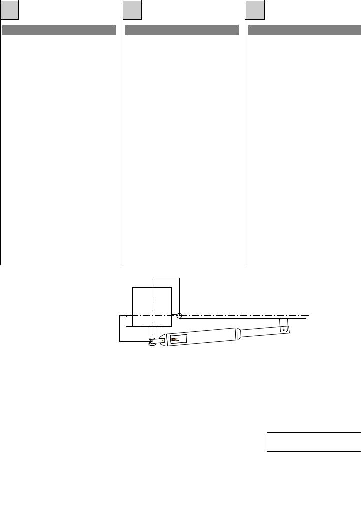
INSTALLAZIONE PISTONE
Il pistone deve essere installato in corrispondenza di un rinforzo longitudinale della struttura dell’anta.
Attacco posteriore
Per determinare il corretto posizionamento dell’attacco posteriore al pilastro vedere Fig. 3 e attenersi alle misure indicate in Tab. 1 (BLUES 20/50) e Tab. 2 (BLUES 21/51).
L’attacco posteriore, sul pilastro, va fatto tramite la piastra 3 e la staffa 2 di Fig. 2.
Se il pilastro è in metallo l’attacco posteriore può essere fatto mediante saldatura (Fig. 4) o viti (Fig. 5).
Se, invece, il pilastro è in cemento, o altro materiale che offra buon aggancio, l’attacco può essere fatto tramite tasselli ad espansione.
Se, infine, il pilastro è in materiale friabile si consiglia di murare 4 viti di lunghezza adeguata su cui fissare la piastra.
Attacco anteriore
L’attacco anteriore va fatto fissando l’apposita staffa (part. 15 di Fig. 2) all’anta del cancello (Fig. 6).
Eventuali compensazioni possono essere ottenute regolando la testina snodata (part. 13 di Fig. 2).
F
INSTALLATION DU PISTON
Le piston doit être installé au niveau du renforcement longitudinal se trouvant sur la structure du battant.
Fixation arrière
Pour déterminer la position correcte de la fixation arrière sur le pilier, voir Fig. 3 et suivre les instructions concernant les dimensions indiquées dans le tableau 1 (BLUES 20/50) et dans le tableau 2 (BLUES 21/51).
La fixation arrière sur le pilier doit être effectuée à l’aide de la plaque 3 et de la bride 2 (voir Fig. 2).
Si le pilier est en métal, la fixation arrière peut être effectuée à l’aide d’une soudure (Fig. 4) ou au moyen de vis (Fig. 5).
Si au contraire le pilier est en ciment, ou dans un autre matériau permettant un bon accrochage, la fixation peut être effectuée à l’aide de vis tamponnées.
Enfin si le pilier est en matériau friable, il est conseillé d’y sceller 4 vis ayant une longueur adéquate sur lesquelles la plaque pourra être fixée.
Fixation avant
La jonction avant s'obtient en fixant l'étrier (détail 15 de la Fig. 2), prévu à cet effet, au battant du portail (fig. 6).
D'éventuelles compensations peuvent être obtenues en réglant la tête articulée (détail 13 de la Fig. 2).
b
c
Fig. 3 / Abb. 3 |
a |
E
INSTALACION PISTON
El pistón se debe instalar en la parte donde está el refuerzo longitudinal de la estructura de la puerta.
Fijación Posterior
Para determinar el correcto posicionamiento de la fijación posterior a la columna, ver Fig. 3 y respetar las medidas indicadas en la tabla 1 (BLUES 20/50) y Tabla 2 (BLUES 21/51).
La fijación posterior, en la columna se realiza con la chapa 3 y la agarradera 2 de la Fig.2.
Si la columna es de metal, la fijación posterior se puede realizar soldandola (Fig. 4) o con tornillos (Fig. 5).
Si por el contrario, la columna es de cemento o en otro material que permita una buena fijación, la misma se puede realizar con tacos a expansión.
Finalmente, si la columna es en material friable se aconseja introducir en la pared 4 tornillos de altura adecuada en los cuales fijar la chapa.
Fijación anterior
La unión delantera debe hacerse fijando la abrazadera expresamente prevista (pieza 15 de la fig. 2) a la hoja de la cancela (fig. 6).
Eventuales compensaciones se pueden obtener regulando la cabeza articulada (pieza 13 de la fig. 2).
I |
|
F |
|
E |
Tab.1 - BLUES 20/50
Misura “a” |
Mesure “a” |
Medida “a” |
mm |
100 |
110 |
120 |
130 |
140 |
Misura “b” |
Mesure “b” |
Medida “b” |
mm |
90 |
100 |
110 |
120 |
110 |
Misura “c” max |
Mesure “c” max |
Medida “c” máx. |
mm |
50 |
60 |
70 |
80 |
90 |
Corsa stelo |
Course tige |
Movimiento perno |
mm |
190 |
210 |
230 |
250 |
250 |
Angolo max apertura |
Angle max d’ouverture |
Angulo máx. apertura |
° |
110 |
115 |
115 |
100 |
90 |
I |
|
F |
|
E |
|
|
Tab.2 - BLUES 21/51 |
|
||
|
|
|
|
|
|
|
|
|||
|
|
|
|
|
|
|
|
|
|
|
Misura “a” |
Mesure “a” |
Medida “a” |
mm |
200 |
230 |
270 |
220 |
|||
Misura “b” |
Mesure “b” |
Medida “b” |
mm |
170 |
140 |
100 |
150 |
|||
Misura “c” max |
Mesure “c” max |
Medida “c” máx. |
mm |
140 |
160 |
200 |
160 |
|||
Corsa stelo |
Course tige |
Movimiento perno |
mm |
370 |
370 |
370 |
370 |
|||
Angolo max apertura |
Angle max d’ouverture |
Angulo máx. apertura |
° |
90 |
90 |
90 |
90 |
|||
8
GB
PISTON INSTALLATION
The piston should be installed in line with a longitudinal reinforcement of the gate frame.
Rear connection
For positioning the rear connection to the post correctly, see Fig. 3 and scrupulously observe the measurements given in Table 1 (BLUES 20/50) and Table 2 (BLUES 50/51).
Use plates 3 and 2 , shown in Fig. 2., for the rear connection to the post.
If the post is metal, the rear plate can be soldered (Fig. 4) or screwed on (Fig. 5).
If the pillar is made of concrete or other material with a suitable solid surface, the plate may be fixed using screw anchors.
If the pillar is made of a brittle material, it is advisable to insert 4 screws of a suitable length to secure the plate.
Front connection
The front connection is accomplished by fixing the relative bracket (part 15 Fig. 2) to the gate (Fig. 6).
Any compensation may be obtained by adjusting the jointed head (part 13 Fig. 2.).
D
INSTALATION DES KOLBENS
Der Kolben muß in Übereinstimmung mit einer Längsverstrebung der Torstruktur montiert werden.
Hintere Befestigung
Um die korrekte Positionierung der hintere Befestigung am Pfosten bestimmen zu können, siehe Abb. 3 und sind die in der Tabelle 1 (BLUES 20/50) und Tabelle 2 (BLUES 21/51) angegebenen Maße zu beachten.
Die hintere Befestigung auf dem Pfosten erfolgt mit Hilfe der Platte 3 und des Bügels 2 der Abb. 2.
Wenn der Pfosten aus Metall besteht, kann die hintere Befestigung durch Anschweißen (Abb. 4) oder mit Schrauben (Abb. 5) erfolgen.
Wenn der Pfosten hingegen aus Beton oder einem anderen Material besteht, das einen guten Halt bietet, kann die Befestigung mit Spreizdübeln erfolgen.
Wenn der Pfosten jedoch aus porösem Material besteht, ist es ratsam, 4 Schrauben entsprechender Länge einzumauern, auf denen die Platte zu befestigen ist.
Vordere Befestigung
Der vordere Anschluß erfolgt durch Befestigung des entsprechenden Bügels (Detail 15 in Abb. 2) auf dem Torflügel (Abb. 6).
Eventuelle Ausgleichungen können durch Regulierung des Gelenkkopfes (Detail 13 in Abb. 2) erzielt werden.
b
c
Fig. 3 / Abb. 3 |
a |
NL
INSTALLATIE VAN DE ZUIGER
De zuiger moet op een horizontale ligger van de vleugelconstructie van de poort geïnstalleerd worden.
Bevestiging aan de achterzijde
Zie fig. 3 om de juiste plaats voor de bevestiging aan de kolom te bepalen. Volg de afmetingen in tabel 1 (BLUES 20/50) en tabel 2 (BLUES 21/51).
De bevestiging aan de kolom wordt gemaakt m.b.v. de platen 3 en 2 zoals blijkt uit fig. 2.
Als de kolom is gemaakt van metaal, kan de bevestiging gelast (fig. 4) of vastgeschroefd (fig. 5) worden.
Wanneer de kolom echter van beton of een ander stevig materiaal is, dan kunt u volstaan met bevestiging d.m.v. keilbouten.
Als de kolom van brokkelig materiaal is gemaakt, is het verstandig om 4 schroeven die lang genoeg moeten zijn in het materiaal te storten of te metselen en daar de bevestigingsplaat aan te bevestigen.
Bevestiging aan de voorzijde
De bevestiging aan de voorzijde moet tot stand gebracht worden door de speciale beugel (det. 15 op fig. 2) aan de poortvleugel vast te maken (fig. 6).
Dit kan eventueel gecompenseerd worden door de scharnierkop (det. 13 op fig. 2) af te stellen.
GB |
|
D |
|
NL |
|
|
|
Tab.1 - BLUES 20/50 |
|
|
|
|
|
|
|
|
|
|
|
|
|
||
|
|
|
|
|
|
|
|
|
|
|
|
Measurement “a” |
Maß “a” |
Maat “a” |
mm |
100 |
110 |
120 |
130 |
140 |
|||
Measurement “b” |
Maß “b” |
Maat “b” |
mm |
90 |
100 |
110 |
120 |
110 |
|||
Measurement “c” max. |
Maß “c” max. |
Maat “c” max. |
mm |
50 |
60 |
70 |
80 |
90 |
|||
Rod stroke |
Kolbenstangenhub |
Slaglengte zuigerstang |
mm |
190 |
210 |
230 |
250 |
250 |
|||
Max. opening angle |
Max. Öffnungswinkel |
Max. openingshoek |
° |
110 |
115 |
115 |
100 |
90 |
|||
GB |
|
D |
|
NL |
|
|
|
|
|
Tab.2 - BLUES 21/51
Measurement “a” |
Maß “a” |
Maat “a” |
mm |
200 |
230 |
270 |
220 |
Measurement “b” |
Maß “b” |
Maat “b” |
mm |
170 |
140 |
100 |
150 |
Measurement “c” max. |
Maß “c” max. |
Maat “c” max. |
mm |
140 |
160 |
200 |
160 |
Rod stroke |
Kolbenstangenhub |
Slaglengte zuigerstang |
mm |
370 |
370 |
370 |
370 |
Max. opening angle |
Max. Öffnungswinkel |
Max. openingshoek |
° |
90 |
90 |
90 |
90 |
9

Fig. 4 / Abb. 4
Fig. 6 / Abb. 6
Fig. 7 / Abb. 7
Fig. 5 / Abb. 5
1. |
Pistone |
1. |
Piston |
|
2. |
Tappo |
2. |
Cap |
|
3. |
Chiave |
3. |
Key |
|
4. |
Valvola di regolazione in |
4. |
Regulating valve for opening |
|
|
apertura |
5. |
Regulating valve for closing |
|
5. |
Valvola di regolazione in |
|||
6. |
Release handle |
|||
|
chiusura |
|||
|
7. |
O-ring |
||
6. |
Manopola di sblocco |
|||
|
|
|||
7. |
Anello OR |
|
|
1. |
Piston |
1. |
Kolben |
2. |
Bouchon |
2. |
Deckel |
3. |
Clé |
3. |
Schlüssel |
4. |
Soupape de régulation en |
4. |
Ventil der Öffnungseinstel- |
|
ouverture |
|
lung |
5. |
Soupape de régulation en |
5. |
Ventil der Schließeinstellung |
|
ferme |
6. |
Drehknopf für die |
6. |
Manette de déblocage |
|
Entriegelung |
7. |
Bague OR |
7. |
O-Ring |
1. |
Pistón |
1. |
Zuiger |
2. |
Tapón |
2. |
Dop |
3. |
Llave |
3. |
Sleutel |
4. |
Válvula de regulación en |
4. |
Krachtregelventiel (tijdens |
|
abertura |
|
opengaan) |
5. |
Válvula de regulación en |
5. |
Krachtregelventiel (tijdens |
|
cierre |
|
sluiten) |
6. |
Manivela de desbloqueo |
6. |
Ontgrendelknop |
7. |
Anillo OR |
7. |
O-ring |
10
 Loading...