


I
F
E
GB
D
NL
ISTEVO
EVO V. 08-2009
ACE500ET-ACE800E
MOTORIDUTTORI ELETTROMECCANICI PER CANCELLI SCORREVOLI
MANUALE ISTRUZIONI E CATALOGO RICAMBI
OPÉRATEURS ÉLECTROMÉCANIQUES POUR PORTAILS COULISSANTS
NOTICE D'INSTRUCTIONS ET CATALOGUE DES PIÈCES DE RECHANGE
MOTORREDUCTORES ELECTROMECÁNICOS PARA CANCELAS CORREDERAS
MANUAL DE INSTRUCCIONES Y CATÁLOGO DE PIEZAS DE REPUESTO
ELECTROMECHANICAL GEARMOTORS FOR SLIDING GATES
INSTRUCTIONS MANUAL AND SPARE PARTS CATALOGUE
ELEKTROMECHANISCHE SCHIEBETORANTRIEBE
BEDIENUNGSANLEITUNG UND ERSATZTEILKATALOG
ELEKTROMECHANISCHE REDUCTIEMOTOREN VOOR SCHUIFPOORTEN
GEBRUIKERSHANDLEIDING EN ONDERDELENCATALOGUS
Telcoma srl - Via L. Manzoni, 11 - Z.I. Campidui - 31015 Conegliano - (TV) Italy
Tel. +39 0438-451099 - Fax +39 0438-451102 - Part. IVA 00809520265
http://www.telcoma.it E-mail: info@telcoma .it

I
INFORMAZIONI GENERALI
I motoriduttori della serie EVO e ACE500ET - ACE800E offrono un'ampia versatilità per l'automazione di cancelli scorrevoli grazie alla gamma di potenze, alle regolazioni di altezza e profondità, ai dispositivi di sicurezza inclusi.
Infatti, nei motori completi di centralina elettronica, sono presenti dei sensori encoder per la rilevazione degli ostacoli.
Per una sicura e corretta installazione vi chiediamo, quindi, di leggere attentamente le presenti istruzioni prestando particolare attenzione al capitolo “AVVERTENZE IMPORTANTI SULL'INSTALLAZIONE” e in seguito di conservarle per una futura consultazione.
F
INFORMATIONS GÉNÉRALES
Les opérateurs de la série EVO et ACE500ET - ACE800E offrent une grande flexibilité pour l'automatisation de portails coulissants grâce à la gamme de puissances, aux réglages de hauteur et profondeur, aux dispositifs de sécurité inclus.
En effet, les moteurs avec logique de commande électronique sont équipés de capteurs à encodeur pour la détection des obstacles.
Pour une installation sûre et correcte, nous vous prions donc de lire attentivement ces instructions en faisant particulièrement attention a u c h a p i t r e « R E C O M M A N D AT I O N S IMPORTANTES POUR L'INSTALLATION » et de les conserver pour toute consultation future.
E
INFORMACIONES GENERALES
Los motorreductores de la serie EVO y ACE500ET - ACE800E ofrecen una amplia versatilidad para la automatización de cancelas correderas gracias a la gama de potencias, a las regulaciones de altura y profundidad y a los dispositivos de seguridad incluidos.
En efecto, en los motores equipados con central electrónica, se encuentran presentes sensores codificadores para la detección de los obstáculos.
Para llevar a cabo una instalación segura y correcta le rogamos, por lo tanto, que lea atentamente las presentes instrucciones prestando una atención particular al capítulo “ADVERTENCIAS IMPORTANTES SOBRE LA INSTALACIÓN” y que las conserve para una consulta futura.
|
DATI TECNICI |
DONNÉES TECHNIQUES |
DATOS TÉCNICOS |
Um |
EVO600 |
EVO600SC |
EVO800 |
EVO1200 |
ACE800E |
ACE500ET |
|
Tensione di alimentazione |
Tension d'alimentation |
Tensión de alimentación |
Vac |
230 |
230 |
230 |
230 |
230 |
230 |
|
|
|
|
|
|
|
|
|
|
|
|
Alimentazione motore |
Alimentation moteur |
Alimentación motor |
V |
230Vac |
230Vac |
230Vac |
230Vac |
24Vdc |
24Vdc |
|
|
|
|
|
|
|
|
|
|
|
|
Peso max cancello |
Poids max. portail |
Peso máx cancela |
Kg |
600 |
600 |
800 |
1200 |
800 |
500 |
|
|
|
|
|
|
|
|
|
|
|
|
Forza di spinta |
Force de poussée |
Fuerza de empuje |
N |
540 |
540 |
640 |
1200 |
640 |
500 |
|
|
|
|
|
|
|
|
|
|
|
|
Corrente max assorbita |
Courant max. absorbé |
Corriente máx absorbida |
A |
3,4 |
3,4 |
3,4 |
5,2 |
2,2 |
1,5 |
|
|
|
|
|
|
|
|
|
|
|
|
Potenza max assorbita |
Puissance max. absorbée |
Potencia máx absorbida |
VA |
800 |
800 |
800 |
1100 |
300 |
200 |
|
|
|
|
|
|
|
|
|
|
|
|
Condensatore |
Condensateur |
Condensator |
μF |
16 |
16 |
20 |
20 |
- |
- |
|
|
|
|
|
|
|
|
|
|
|
|
Coppia nominale |
Couple nominal |
Par nominal |
Nm |
21 |
21 |
24 |
45 |
24 |
18 |
|
|
|
|
|
|
|
|
|
|
|
|
Velocità cancello |
Vitesse portail |
Velocidad cancela |
m/min |
10 |
10 |
10 |
10 |
11 |
11 |
|
|
|
|
|
|
|
|
|
|
|
|
Temp. di funzionamento |
Température de fonctionnement |
Temp. de funcionamiento |
°C |
-20+70 |
-20+70 |
-20+70 |
-20+70 |
-20+70 |
-20+70 |
|
|
|
|
|
|
|
|
|
|
|
|
Intervento termoprotezione |
Intervention protection thermique |
Intervención termoprotección |
°C |
150 |
150 |
150 |
150 |
- |
- |
|
|
|
|
|
|
|
|
|
|
|
|
Grado di protezione |
Indice de protection |
Grado de protección |
IP |
54 |
54 |
54 |
54 |
54 |
54 |
|
|
|
|
|
|
|
|
|
|
|
|
Encoder |
Encodeur |
Encoder |
|
SI/YES |
SI/YES |
SI/YES |
SI/YES |
SI/YES |
SI/YES |
|
|
|
|
|
|
|
|
|
|
|
|
Intermittenza lavoro |
Intermittence travail |
Intermitencia trabajo |
% |
40 |
40 |
60 |
60 |
60 |
60 |
|
|
|
|
|
|
|
|
|
|
|
|
Peso |
Poids |
Peso |
Kg |
13 |
13 |
15 |
17 |
13 |
12 |
|
|
|
|
|
|
|
|
|
|
|
|
Finecorsa elettronico |
Fin de course électronique |
Fin de carrera electrónico |
|
SI/YES |
- |
SI/YES |
SI/YES |
SI/YES |
SI/YES |
|
|
|
|
|
|
|
|
|
|
|
|
Finecorsa meccanico |
Fin de course mécanique |
Fin de carrera mecánico |
|
- |
SI/YES |
- |
- |
- |
- |
|
|
|
|
|
|
|
|
|
|
|
|
Centrale elettronica incorporata |
Logique électronique incorporée |
Central electrónica incorporada |
|
SI/YES |
- |
SI/YES |
SI/YES |
SI/YES |
SI/YES |
|
|
|
|
|
|
|
|
|
|
|
|
Classe di isolamento |
Classe d'isolement |
Clase de aislamiento |
|
F |
F |
F |
F F |
|
- |
|
|
|
|
|
|
|
|
|
|
|
|
Lubrificante grasso |
Lubrifiant graisse |
Lubrificante grasa |
|
TS 10 |
TS 10 |
- |
- |
TS10 |
TS10 |
|
|
|
|
|
|
|
|
|
|
|
|
Lubrificante olio |
Lubrifiant huile |
Lubrificante aceite |
|
- |
- |
TS 20 |
TS 40 |
- |
- |
|
|
|
|
|
|
|
|
|
|
|
2
GB
GENERAL INFORMATION
The EVO and ACE500ET - ACE800E series gearmotors offer ample flexibility for the automation of sliding gates thanks to the range of powers, height and depth adjustment and included safety devices.
In fact, the motor with electronic control unit includes encoder sensors for obstacle detection.
Therefore, in order that the installation is performed in a safe and correct manner, we kindly ask you to carefully read the present instructions giving particular attention to chapter “IMPORTANT INSTALLATION WARNINGS" and to keep these instructions in a safe place for future reference.
D
ALLGEMEINE AUSKÜNFTE
Die Antriebe der Serien EVO und ACE500ET - ACE800E bieten dank den verschiedenen Leistungen, den Höhenund Tiefenverstellungen u n d d e n e i n g e s c h l o s s e n e n S i c h e r h e i t s v o r r i c h t u n g e n e i n e g r o ß e Vielseitigkeit bei der Automatisierung von Schiebetoren.
Die mit elektronischer Steuerung ausgestatteten Antriebe verfügen über Encodersensoren zur Wahrnehmung der Hindernisse.
Für eine sichere und korrekte Installation bitten wir Sie daher, die vorliegenden Anweisungen und insbesondere das Kapitel „WICHTIGE HINWEISE ZUR INSTALLATION „ aufmerksam zu lesen und sie dann für ein zukünftiges Nachschlagen aufzubewahren.
NL
ALGEMENE INFORMATIE
De reductiemotoren uit de serie EVO en ACE500ET - ACE800E zijn uitermate veelzijdig voor het automatiseren van schuifpoorten dankzij een heel scala aan vermogen, afstelling in hoogte en diepte, veiligheidsinrichtingen inbegrepen.
In de motoren voorzien van een elektronische b e s t u r i n g s e e n h e i d , b e v i n d e n z i c h encodersensoren voor obstakeldetectie .
Voor een veilige en correcte installatie verzoeken wij u daarom deze aanwijzingen aandachtig door te lezen en in het bijzonder het hoofdstuk “BELANGRIJKE AANWIJZINGEN VOOR HET INSTALLEREN” en ze daarna te bewaren om ze in de toekomst te kunnen raadplegen.
|
TECHNICAL SPECIFICATIONS |
TECHNISCHE DATEN |
TECHNISCHE GEGEVENS |
Um |
EVO600 |
EVO600SC |
EVO800 |
EVO1200 |
ACE800E |
ACE500ET |
|
Power Supply voltage |
Spannungsversorgung |
Spanning stroomvoorziening |
Vac |
230 |
230 |
230 |
230 |
230 |
230 |
|
|
|
|
|
|
|
|
|
|
|
|
Motor power supply |
Motorversorgung |
Stroomvoorziening motor |
V |
230Vac |
230Vac |
230Vac |
230Vac |
24Vdc |
24Vdc |
|
|
|
|
|
|
|
|
|
|
|
|
Max. gate weight |
Höchstgewicht des Tors |
Max gewicht poort |
Kg |
600 |
600 |
800 |
1200 |
800 |
500 |
|
|
|
|
|
|
|
|
|
|
|
|
Thrust force |
Schubkraft |
Duwkracht |
N |
540 |
540 |
640 |
1200 |
640 |
500 |
|
|
|
|
|
|
|
|
|
|
|
|
Max. absorbed current |
Max. Stromaufnahme |
Mas opgenomen stroom |
A |
3,4 |
3,4 |
3,4 |
5,2 |
2,2 |
1,5 |
|
|
|
|
|
|
|
|
|
|
|
|
Max absorbed power |
Max. Leistungsaufnahme |
Max opgenomen vermogen |
VA |
800 |
800 |
800 |
1100 |
300 |
200 |
|
|
|
|
|
|
|
|
|
|
|
|
Capacitor |
Kondensator |
Condensator |
μF |
16 |
16 |
20 |
20 |
- |
- |
|
|
|
|
|
|
|
|
|
|
|
|
Nominal torque |
Nenndrehmoment |
Nominale koppel |
Nm |
21 |
21 |
24 |
45 |
24 |
18 |
|
|
|
|
|
|
|
|
|
|
|
|
Gate speed |
Torgeschwindigkeit |
Snelheid poort |
m/min |
10 |
10 |
10 |
10 |
11 |
11 |
|
|
|
|
|
|
|
|
|
|
|
|
Operating time |
Betriebstemp. |
Bedrijfstemp |
°C |
-20+70 |
-20+70 |
-20+70 |
-20+70 |
-20+70 |
-20+70 |
|
|
|
|
|
|
|
|
|
|
|
|
Thermal cut-out |
Auslösung des Wärmeschutzes |
Inwerkingtreding oververhittingsbeveiliging |
°C |
150 |
150 |
150 |
150 |
- |
- |
|
|
|
|
|
|
|
|
|
|
|
|
Protection class |
Schutzart |
Beschermingsklasse |
IP |
54 |
54 |
54 |
54 |
54 |
54 |
|
|
|
|
|
|
|
|
|
|
|
|
Encoder |
Encoder |
Encoder |
|
SI/YES |
SI/YES |
SI/YES |
SI/YES |
SI/YES |
SI/YES |
|
|
|
|
|
|
|
|
|
|
|
|
Operating intervals |
Betriebsintermittenz |
Onderbreking bedrijf |
% |
40 |
40 |
60 |
60 |
60 |
60 |
|
|
|
|
|
|
|
|
|
|
|
|
Weight |
Gewicht |
Gewicht |
Kg |
13 |
13 |
15 |
17 |
13 |
12 |
|
|
|
|
|
|
|
|
|
|
|
|
Electronic limit switch |
Elektronischer Endschalter |
Elektronische eindschakelaar |
|
SI/YES |
- |
SI/YES |
SI/YES |
SI/YES |
SI/YES |
|
|
|
|
|
|
|
|
|
|
|
|
Mechanical stop |
Mechanischer Endschalter |
Mechanische eindaanslag |
|
- |
SI/YES |
- |
- |
- |
- |
|
|
|
|
|
|
|
|
|
|
|
|
Incorporated electronic control unit |
Eingebaute elektronische Steuerung |
Ingebouwde besturingseenheid |
|
SI/YES |
- |
SI/YES |
SI/YES |
SI/YES |
SI/YES |
|
|
|
|
|
|
|
|
|
|
|
|
Insulation class |
Isolationsklasse |
Isoleringsklasse |
|
F |
F |
F |
F F |
|
- |
|
|
|
|
|
|
|
|
|
|
|
|
Grease lubricant |
Fettschmierung |
Smeermiddel vet |
|
TS 10 |
TS 10 |
- |
- |
TS10 |
TS10 |
|
|
|
|
|
|
|
|
|
|
|
|
Oil lubricant |
Ölschmierung |
Smeermiddel olie |
|
- |
- |
TS 20 |
TS 40 |
- |
- |
|
|
|
|
|
|
|
|
|
|
|
3

|
I |
|
|
F |
|
|
E |
|
|
||||||||||||||||||||||||||||||||||||||||||||||||||||||||||||||||||||||||||||||||||||||||
|
|
|
|
|
|
|
|
|
|
|
|
|
|
|
|
|
|
|
|
|
|
|
|
|
|
|
|
|
|
|
|
|
|
|
|
|
|
|
|
|
|
|
|
|
|
|
|
|
|
|
|
|
|
|
|
|
|
|
|
|
|
|
|
|
|
|
|
|
|
|
|
|
|
|
|
|
|
|
|
|
|
|
|
|
|
|
|
|
|
|
|
|
|
|
|
|
|
|
QUADRO D'INSIEME |
|
|
VUE D'ENSEMBLE |
|
VISIÓN DE CONJUNTO |
|||||||||||||||||||||||||||||||||||||||||||||||||||||||||||||||||||||||||||||||||||||||||||
|
1. Supporto per lampeggiatore + antenna |
|
1. Support pour clignotant + antenne |
1. Soporte para luz intermitente + antena |
|||||||||||||||||||||||||||||||||||||||||||||||||||||||||||||||||||||||||||||||||||||||||||||
|
2. Radiocomando |
|
2. Radiocommande |
2. Radiocontrol |
|||||||||||||||||||||||||||||||||||||||||||||||||||||||||||||||||||||||||||||||||||||||||||||
|
3. Lampeggiatore |
|
3. Clignotant |
3. Luz intermitente |
|||||||||||||||||||||||||||||||||||||||||||||||||||||||||||||||||||||||||||||||||||||||||||||
|
4. Antenna |
|
4. Antenne |
4. Antena |
|||||||||||||||||||||||||||||||||||||||||||||||||||||||||||||||||||||||||||||||||||||||||||||
|
5. Selettore |
|
5. Sélecteur |
5. Selector |
|||||||||||||||||||||||||||||||||||||||||||||||||||||||||||||||||||||||||||||||||||||||||||||
|
6. Fotocellula |
|
6. Photocellule |
6. Fotocélula |
|||||||||||||||||||||||||||||||||||||||||||||||||||||||||||||||||||||||||||||||||||||||||||||
|
7. Cartello di avvertenza |
|
7. Panneau de signalisation |
7. Cartel de advertencia |
|||||||||||||||||||||||||||||||||||||||||||||||||||||||||||||||||||||||||||||||||||||||||||||
|
8. Bordo in gomma |
|
8. Bord en caoutchouc |
8. Borde de goma |
|||||||||||||||||||||||||||||||||||||||||||||||||||||||||||||||||||||||||||||||||||||||||||||
|
9. Linea di alimentazione |
|
9. Ligne d'alimentation |
9. Línea de alimentación |
|||||||||||||||||||||||||||||||||||||||||||||||||||||||||||||||||||||||||||||||||||||||||||||
|
10. Interruttore generale |
|
10. Interrupteur général |
10. Interruptor general |
|||||||||||||||||||||||||||||||||||||||||||||||||||||||||||||||||||||||||||||||||||||||||||||
|
11. Interruttore differenziale |
|
11. Interrupteur différentiel |
11. Interruptor diferencial |
|||||||||||||||||||||||||||||||||||||||||||||||||||||||||||||||||||||||||||||||||||||||||||||
|
12. Magnete di finecorsa |
|
12. Aimant de fin de course |
12. Magneto de fin de carrera |
|||||||||||||||||||||||||||||||||||||||||||||||||||||||||||||||||||||||||||||||||||||||||||||
|
13. Cremagliera |
|
13. Crémaillère |
13. Cremallera |
|||||||||||||||||||||||||||||||||||||||||||||||||||||||||||||||||||||||||||||||||||||||||||||
|
14. Motoriduttore |
|
14. Opérateur |
14. Motorreductor |
|||||||||||||||||||||||||||||||||||||||||||||||||||||||||||||||||||||||||||||||||||||||||||||
|
15. Contropiastra di fondazione (optional) |
|
15. Contre-plaque de fondation (option) |
15. Contraplaca de cimentación (facultativo) |
|||||||||||||||||||||||||||||||||||||||||||||||||||||||||||||||||||||||||||||||||||||||||||||
|
16. Piastra di fissaggio |
|
16. Plaque de fixation |
16. Placa de fijación |
|||||||||||||||||||||||||||||||||||||||||||||||||||||||||||||||||||||||||||||||||||||||||||||
|
|
|
|
|
|
|
|
|
|
|
|
|
|
|
|
|
|
|
|
|
|
|
|
|
|
|
|
|
|
|
|
|
|
|
|
|
|
|
|
|
|
|
|
|
|
|
|
|
|
|
|
|
|
|
|
|
|
|
|
|
|
|
|
|
|
|
|
|
|
|
|
|
|
|
|
|
|
|
|
|
|
|
|
|
|
|
|
|
|
|
|
|
|
|
|
|
|
|
|
|
|
|
|
|
|
|
|
|
|
|
|
|
|
|
|
|
|
|
|
|
|
|
|
|
|
|
|
|
|
|
|
|
|
|
|
|
|
|
|
|
|
|
|
|
|
|
|
|
|
|
|
|
|
|
|
|
|
|
|
|
|
|
|
|
|
|
|
|
|
|
|
|
|
|
|
|
|
|
|
|
|
|
|
|
|
|
|
|
|
|
|
|
|
|
|
|
|
|
|
|
|
|
|
|
|
|
|
|
|
|
|
|
|
|
|
|
|
|
|
|
|
|
|
|
|
|
|
|
|
|
|
|
|
|
|
|
|
|
|
|
|
|
|
|
|
|
|
|
|
|
|
|
|
|
|
|
|
|
|
|
|
|
|
|
|
|
|
|
|
|
|
|
|
|
|
|
|
|
|
|
|
|
|
|
|
|
|
|
|
|
|
|
|
|
|
|
|
|
|
|
|
|
|
|
|
|
|
|
|
|
|
|
|
|
|
|
|
|
|
|
|
|
|
|
|
|
|
|
|
|
|
|
|
|
|
|
|
|
|
|
|
|
|
|
|
|
|
|
|
|
|
|
|
|
|
|
|
|
|
|
|
|
|
|
|
|
|
|
|
|
|
|
|
|
|
|
|
|
|
|
|
|
|
|
|
|
|
|
|
|
|
|
|
|
|
|
|
|
|
|
|
|
|
|
|
|
|
|
|
|
|
|
|
|
|
|
|
|
|
|
|
|
|
|
|
|
|
|
|
|
|
|
|
|
|
|
|
|
|
|
|
|
|
|
|
|
|
|
|
|
|
|
|
|
|
|
|
|
|
|
|
|
|
|
|
|
|
|
|
|
|
|
|
|
|
|
|
|
|
|
|
|
|
|
|
|
|
|
|
|
|
|
|
|
|
|
|
|
|
|
|
|
|
|
|
|
|
|
|
|
|
|
|
|
|
|
|
|
|
|
|
|
|
|
|
|
|
|
|
|
|
|
|
|
|
|
|
|
|
|
|
|
|
|
|
|
|
|
|
|
|
|
|
|
|
|
|
|
|
|
|
|
|
|
|
|
|
|
|
|
|
|
|
|
|
|
|
|
|
|
|
|
|
|
|
|
|
|
|
|
|
|
|
|
|
|
|
|
|
|
|
|
|
|
|
|
|
|
|
|
|
|
|
|
|
|
|
|
|
|
|
|
|
|
|
|
|
|
|
|
|
|
|
|
|
|
|
|
|
|
|
|
|
|
|
|
|
|
|
|
|
|
|
|
|
|
|
|
|
|
|
|
|
|
|
|
|
|
|
|
|
|
|
|
|
|
|
|
|
|
|
|
|
|
|
|
|
|
|
|
|
|
|
|
|
|
|
|
|
|
|
|
|
|
|
|
|
|
|
|
|
|
|
|
|
|
|
|
|
|
|
|
|
|
|
|
|
|
|
|
|
|
|
|
|
|
|
|
|
|
|
|
|
|
|
|
|
|
|
|
|
|
|
|
|
|
|
|
|
|
|
|
|
|
|
|
|
|
|
|
|
|
|
|
|
|
|
|
|
|
|
|
|
|
|
|
|
|
|
|
|
|
|
|
|
|
|
|
|
|
|
|
|
|
|
|
|
|
|
|
|
|
|
|
|
|
|
|
|
|
|
|
|
|
|
|
|
|
|
|
|
|
|
|
|
|
|
|
|
|
|
|
|
|
|
|
|
|
|
|
|
|
|
|
|
|
|
|
|
|
|
|
|
|
|
|
|
|
|
|
|
|
|
|
|
|
|
|
|
|
|
|
|
|
|
|
|
|
|
|
|
|
|
|
|
|
|
|
|
|
|
|
|
|
|
|
|
|
|
|
|
|
|
|
|
|
|
|
|
|
|
|
|
|
|
|
|
|
|
|
|
|
|
|
|
|
|
|
|
|
|
|
|
|
|
|
|
|
|
|
|
|
|
|
|
|
|
|
|
|
|
|
|
|
|
|
|
|
|
|
|
|
|
|
|
|
|
|
|
|
|
|
|
|
|
|
|
|
|
|
|
|
|
|
|
|
|
|
|
|
|
|
|
|
|
|
|
|
|
|
|
|
|
|
|
|
|
|
|
|
|
|
|
|
|
|
|
|
|
|
|
|
|
|
|
|
|
|
|
|
|
|
|
|
|
|
|
|
|
|
|
|
|
|
|
|
|
|
|
|
|
|
|
|
|
|
|
|
|
|
|
|
|
|
|
|
|
|
|
|
|
|
|
|
|
|
|
|
|
|
|
|
|
|
|
|
|
|
|
|
|
|
|
|
|
|
|
|
|
|
|
|
|
|
|
|
|
|
|
|
|
|
|
|
|
|
|
|
|
|
|
|
|
|
|
|
|
|
|
|
|
|
|
|
|
|
|
|
|
|
|
|
|
|
|
|
|
|
|
|
|
|
|
|
|
|
|
|
|
|
|
|
|
|
|
|
|
|
|
|
|
|
|
|
|
|
|
|
|
|
|
|
|
|
|
|
|
|
|
|
|
|
|
|
|
|
|
|
|
|
|
|
|
|
|
|
|
|
|
|
|
|
|
|
|
|
|
|
|
|
|
|
|
|
|
|
|
|
|
|
|
|
|
|
|
|
|
|
|
|
|
|
|
|
|
|
|
|
|
|
|
|
|
|
|
|
|
|
|
|
|
|
|
|
|
|
|
|
|
|
|
|
|
|
|
|
|
|
|
|
|
|
|
|
|
|
|
|
|
|
|
|
|
|
|
|
|
|
|
|
|
|
|
|
|
|
|
|
|
|
|
|
|
|
|
|
|
|
|
|
|
|
|
|
|
|
|
|
|
|
|
|
|
|
|
|
|
|
|
|
|
|
|
|
|
|
|
|
|
|
|
|
|
|
|
|
|
|
|
|
|
|
|
|
|
|
|
|
|
|
|
|
|
|
|
|
|
|
|
|
|
|
|
|
|
|
|
|
|
|
|
|
|
|
|
|
|
|
|
|
|
|
|
|
|
|
|
|
|
|
|
|
|
|
|
|
|
|
|
|
|
|
|
|
|
|
|
|
|
|
|
|
|
|
|
|
|
|
|
|
|
|
|
|
|
|
|
|
|
|
|
|
|
|
|
|
|
|
|
|
|
|
|
|
|
|
|
|
|
|
|
|
|
|
|
|
|
|
|
|
|
|
|
|
|
|
|
|
|
|
|
|
|
|
|
|
|
|
|
|
|
|
|
|
|
|
|
|
|
|
|
|
|
|
|
|
|
|
|
|
|
|
|
|
|
|
|
|
|
|
|
|
|
|
|
|
|
|
|
|
|
|
|
|
|
|
|
|
|
|
|
|
|
|
|
|
|
|
|
|
|
|
|
|
|
|
|
|
|
|
|
|
|
|
|
|
|
|
|
|
|
|
|
|
|
|
|
|
|
|
|
|
|
|
|
|
|
|
|
|
|
|
|
|
|
|
|
|
|
|
|
|
|
|
|
|
|
|
|
|
|
|
|
|
|
|
|
|
|
|
|
|
|
|
|
|
|
|
|
|
|
|
|
|
|
|
|
|
|
|
|
|
|
|
|
|
|
|
|
|
|
|
|
|
|
|
|
|
|
|
|
|
|
|
|
|
|
|
|
|
|
|
|
|
|
|
|
|
|
|
|
|
|
|
|
|
|
|
|
|
|
|
|
|
|
|
|
|
|
|
|
|
|
|
|
|
|
|
|
|
|
|
|
|
|
|
|
|
|
|
|
|
|
|
|
|
|
|
|
|
|
|
|
|
|
|
|
|
|
|
|
|
|
|
|
|
|
|
|
|
|
|
|
|
|
|
|
|
|
|
|
|
|
|
|
|
|
|
|
|
|
|
|
|
|
|
|
|
|
|
|
|
|
|
|
|
|
|
|
|
|
|
|
|
|
|
|
|
|
|
|
|
|
|
|
|
|
|
|
|
|
|
|
|
|
|
|
|
|
|
|
|
|
|
|
|
|
|
|
|
|
|
|
|
|
|
|
|
|
|
|
|
|
|
|
|
|
|
|
|
|
|
|
|
|
|
|
|
|
|
|
|
|
|
|
|
|
|
|
|
|
|
|
|
|
|
|
|
|
|
|
|
|
|
|
|
|
|
|
|
|
|
|
|
|
|
|
|
|
|
|
|
|
|
|
|
|
|
|
|
|
|
|
|
|
|
|
|
|
|
|
|
|
|
|
|
|
|
|
|
|
|
|
|
|
|
|
|
|
|
|
|
|
|
|
|
|
|
|
|
|
|
|
|
|
|
|
|
|
|
|
|
|
|
|
|
|
|
|
|
|
|
|
|
|
|
|
|
|
|
|
|
|
|
|
|
|
|
|
|
|
|
|
|
|
|
|
|
|
|
|
|
|
|
|
|
|
|
|
|
|
|
|
|
|
|
|
|
|
|
|
|
|
|
|
|
|
|
|
|
|
|
|
|
|
|
|
|
|
|
|
|
|
|
|
|
|
|
|
|
|
|
|
|
|
|
|
|
|
|
|
|
|
|
|
|
|
|
|
|
|
|
|
|
|
|
|
|
|
|
|
|
|
|
|
|
|
|
|
|
|
|
|
|
|
|
|
|
|
|
|
|
|
|
|
|
|
|
|
|
|
|
|
|
|
|
|
|
|
|
|
|
|
|
|
|
|
|
|
|
|
|
|
|
|
|
|
|
|
|
|
|
|
|
|
|
|
|
|
|
|
|
|
|
|
|
|
|
|
|
|
|
|
|
|
|
|
|
|
|
|
|
|
|
|
|
|
|
|
|
|
|
|
|
|
|
|
|
|
|
|
|
|
|
|
|
|
|
|
|
|
|
|
|
|
|
|
|
|
|
|
|
|
|
|
|
|
|
|
|
|
|
|
|
|
|
|
|
|
|
|
|
|
GB |
|
|
|
D |
|
|
|
NL |
|
|
|
|
|
|
|
|
|
||||
|
GENERAL LAYOUT |
|
|
GESAMTANSICHT |
|
|
OVERZICHTSTEKENING |
|||
1. Aerial + flashing light support |
|
1. Halterung für Blinkleuchte + Antenne |
|
1. Steun voor knipperlicht + antenne |
||||||
2. Remote control |
|
2. Funksteuerung |
|
2. Afstandsbediening |
||||||
3. Flashing light |
|
3. Blinkleuchte |
|
3. Knipperlicht |
||||||
4. Aerial |
|
4. Antenne |
|
4. Antenne |
||||||
5. Selector switch |
|
5. Schlüsseltaster |
|
5. Keuzeschakelaar |
||||||
6. Photocell |
|
6. Fotozelle |
|
6. Fotocel |
||||||
7. Warning sign |
|
7. Warnschild |
|
7. Waarschuwingsbord |
||||||
8. Rubber edge |
|
8. Gummileiste |
|
8. Rubber rand |
||||||
9. Power line |
|
9. Versorgungslinie |
|
9. Leiding stroomvoorziening |
||||||
10. Main switch |
|
10. Hauptschalter |
|
10. Hoofdschakelaar |
||||||
11. Differential switch |
|
11. Differentialschalter |
|
11.Differentiaalschakelaar |
||||||
12. Limit switch magnet |
|
12. Endschaltermagnet |
|
12. Magneet eindschakelaar |
||||||
13. Rack |
|
13. Zahnstange |
|
13. Tandheugel |
||||||
14. Gearmotor |
|
14. Getriebemotor |
|
14. Reductiemotor |
||||||
15. Foundation base plate (optional) |
|
15. Fundamentgegenplatte (Optional) |
|
15. Contrafunderingsplaat(apart leverbaar) |
||||||
16. Fixing plate |
|
16. Ankerplatte |
|
16. Bevestigingsplaat |
||||||
4
I
VERIFICHE PRELIMINARI
Prima di passare all' installazione si consiglia di effettuare le seguenti verifiche e operazioni.
1.La struttura del cancello deve essere solida e appropriata.
2.Durante la sua corsa, il cancello non deve presentare sbandamenti laterali.
3.Il sistema ruote/rotaia inferiore e rulli/guida superiore deve scorrere regolarmente senza attriti.
4.Devono essere installate delle battute di arresto meccanico del cancello scorrevole sia in apertura che in chiusura.
5.Nei cancelli preesistenti eliminare l'eventuale serratura manuale.
6.Portare alla base del cancello le canaline, aventi un diametro, 25÷50 mm, necessarie per il passaggio dei vari cavi elettrici quali
a l i m e n t a z i o n e d i r e t e , f o t o c e l l u l a , lampeggiatore, selettore a chiave, etc.
F
CONTRÔLES PRÉLIMINAIRES
Avant de passer à l'installation, nous conseillons d'effectuer les vérifications et opérations qui suivent.
1.La structure du portail doit être solide et appropriée.
2.Durant sa course, le portail ne doit pas présenter d'inclinaisons latérales.
3.L e s y s t è m e r o u e s / r a i l i n f é r i e u r e t galets/glissière supérieure doit coulisser régulièrement sans frottements.
4.Des butées d'arrêt mécanique du portail coulissant doivent être installées aussi bien en ouverture qu'en fermeture.
5.Dans les portails préexistants, éliminer l'éventuelle serrure manuelle.
6.Amener jusqu'à la base du portail les gaines, d'un diamètre de 25÷50 mm, nécessaires pour le passage des différents câbles électriques comme l'alimentation de secteur, les photocellules, le clignotant, le sélecteur a clé, etc.
E
VERIFICACIONES PRELIMINARES
Antes de pasar a la instalación le aconsejamos que efectúe las siguientes verificaciones y operaciones.
1.La estructura de la cancela tiene que ser sólida y apropiada.
2.Durante su recorrido, la cancela no tiene que presentar inclinaciones laterales.
3.El sistema ruedas/carril inferior y rodillos/guía superior tiene que desplazarse regularmente sin roces.
4.Tienen que instalarse topes de parada mecánicos de la cancela corredera tanto en la apertura como en el cierre.
5.En las cancelas preexistentes elimine la eventual cerradura manual.
6.Coloque en la base de la cancela los canales, con un diámetro de 25÷50 mm, que son necesarios para hacer pasar los diversos cables eléctricos como el de alimentación de red, el de la fotocélula, el de la luz intermitente, el del selector con llave, etc.
GB
PRELIMINARY CONTROLS
The following controls and operations should ideally be performed before commencing with installation.
1.The gate structure must be solid and appropriate.
2.The gate should have no lateral deviation during its movement.
3.The lower track/wheel and upper guide/wheel system must slide evenly without friction.
4.The sliding gate mechanical stops must be installed both in opening as well as in closing.
5.Remove the manual lock of already existing gates.
6.A channel with a diameter of 25÷50 mm must be taken to the base of the gate in order to pass the cables for the mains power supply, photocell, flashing light, key operated selector switch, etc.
D
ÜBERPRÜFUNGEN UND VORBEREITUNGEN
Bevor man auf die Installation übergeht, sollten folgende Überprüfungen und Vorgänge ausgeführt werden:
1.Die Torstruktur muss solide und geeignet sein.
2.Das Tor darf während seines Laufs seitlich nicht entgleisen.
3.Die Räder auf der unteren Schiene und die Rollen in der oberen Führung müssen regelmäßig und ohne Reibungen gleiten.
4.Das Schiebetor muss über mechanische Anschläge sowohl in der Öffnung
als auch in der Schließung verfügen.
5.An bereits vorhandenen Toren muss das eventuelle manuelle Schloss entfernt werden.
6.Die Kanäle mit einem Durchmesser von
2 5 ÷ 5 0 m m z u m D u r c h f ü h r e n d e r v e r s c h i e d e n e n e l e k t r i s c h e n K a b e l ( N e t z s t r o m v e r s o r g u n g , F o t o z e l l e , Blinkleuchte, Schlüsseltaster, usw.) bis zur Basis des Tors führen.
NL
CONTROLES VOORAF
Voordat u tot installatie over gaat is het raadzaam onderstaande controles en handelingen uit te voeren.
1.De poort moet een stevige en adequate structuur hebben.
2.Tijdens zijn loop mag de poort niet zijdelings uit het geleidingssysteem komen.
3.Het systeem wielen/rails aan de onderzijde en rollen/geleiding aan de bovenzijde moet regelmatig verschuiven zonder wrijvingen.
4.Er dienen mechanische stops bij de schuifpoort zowel aan de openingsals sluitzijde aangebracht te worden.
5.Bij reeds bestaande poorten dient u een eventueel slot met handbediening weg te halen.
6.Breng aan de onderzijde van de poort de kabelgootjes met een doorsnede van, 25÷50 mm, waardoor de verschillende
elektriciteitskabels zoals stroomtoevoer van h e t n e t , f o t o c e l , k n i p p e r l i c h t , sleutelschakelaar, etc. moeten lopen.
5

I
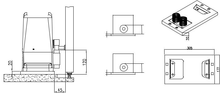
INSTALLAZIONE SU PIASTRA DI
FONDAZIONE (OPZIONALE)
E79G;D7 G@A E53HA 6; 8A@63L;A@7 F7@7@6A 5A@FA 67>>7 ?;EGD7 67>>3 B;3EFD3 6; 8A@63L;A@7
;9
Prestare molta attenzione al verso di montaggio. I fori per il passaggio delle canaline devono trovarsi a sinistra (fig.2).
>>A99;3D7 @7>>A E53HA >7 53@3>;@7 6;3? ??j B7D ;> B3EE399;A 67; 53H; 6; 3>;?7@F3L;A@7 7 6; 5A>>793?7@FA 7EF7D@A
@@793D7 @7> 53>57EFDGLLA >7 53@3>;@7 7 >3 B;3EFD3 6; 8A@63L;A@7 6ABA 3H7D@7 5A@FDA>>3FA 5A@ > 3GE;>;A 6; G@3 >;H7>>3 >7 CGAF7 7 > AD;LLA@F3>;FZ +;EB7FF3D7 ?;EGD7 7 3@9A>; ;@6;53F; ;@ ;9 3 ;@EF3>>3L;A@7 67EFD3 7 ;@;9 4 ;@EF3>>3L;A@7 E;@;EFD3 D3BBD7E7@F3@A ;> ?;@;?A ;@6;EB7@E34;>7 B7D G@ B7D87FFA 355ABB;3?7@FA FD3 B;9@A@7 7 5D7?39>;7D3
Prestare molta attenzione alle quote indicate nella figura 4.
H 7 @ F G 3 > ; B ; 5 5 A > 7 ; ? B D 7 5 ; E ; A @ ; 6 ; BAE;L;A@3?7@FA ;@ 3>F7LL3 7 BDA8A@6;FZ 67>>3
B;3EFD3 6; 8A@63L;A@7 BAEEA@A 5A?G@CG7 7EE7D7 5ADD7FF7 397@6A EG557EE;H3?7@F7 EG> E;EF7?3 6; D79A>3L;A@7 67> ?AFAD;6GFFAD7;EE3D7 ;> ?AFAD7 EG>>3 B;3EFD3 EA>A CG3@6A ;> 53>57EFDGLLA E3DZ B7D87FF3?7@F7 EA>;6;8;53FA 7 3E5;G93FA
F
INSTALLATION SUR PLAQUE DE FONDATION (OPTION)
D7GE7D G@ FDAG 7@ F7@3@F 5A?BF7 67E 6;?7@E;A@E 67 >3 B>3CG7 67 8A@63F;A@ ;9
Faire très attention au sens de montage. Les trous pour le passage des gaines doivent se trouver à gauche (fig. 2).
%A97D 63@E >7 FDAG >7E 93;@7E 6;3? ??j BAGD >7 B3EE397 67E 5\4>7E 6 3>;?7@F3F;A@ 7F 67 5A@@7J;A@ 7JF`D;7GD7
'AK7D 63@E >7 4`FA@ >7E 93;@7E 7F >3 B>3CG7 67 8A@63F;A@ 3BD_E 7@ 3HA;D 5A@FDh>` 3H75 G@ @;H73G >7E 6;EF3@57E 7F > :AD;LA@F3>;F` +7EB75F7D >7E ?7EGD7E 7F >7E 3@9>7E ;@6;CG`E 63@E >3 ;9 3 ;@EF3>>3F;A@ 6DA;F7 7F 63@E >3;9 4 ;@EF3>>3F;A@ 93G5:7
>>7E D7BD`E7@F7@F >7 ?;@;?G? ;@6;EB7@E34>7 BAGD G@ 355AGB>7?7@F B3D83;F 7@FD7 B;9@A@ 7F 5D`?3;>>_D7
Faire très attention aux mesures indiquées dans la figure 4.
%7E `H7@FG7>>7E B7F;F7E ;?BD`5;E;A@E 67
BAE;F;A@@7?7@F 7@ :3GF7GD 7F BDA8A@67GD 67 >3 B>3CG7 67 8A@63F;A@ B7GH7@F aFD7 5ADD;9`7E
63@E FAGE >7E 53E 7@ 39;EE3@F EG557EE;H7?7@F EGD >7 EKEF_?7 67 D`9>397 67 > AB`D3F7GD
;J7D >7 ?AF7GD EGD >3 B>3CG7 G@;CG7?7@F CG3@6 >7 4`FA@ E7D3 5A?B>_F7?7@F EA>;6;8;` 7F E75
E
INSTALACIÓN SOBRE PLACA DE CIMENTACIÓN (OPCIONAL)
875Fl7 G@3 7J53H35;g@ 67 5;?7@F35;g@ F7@;7@6A 7@ 5G7@F3 >3E ?76;63E 67 >3 B>353
67 5;?7@F35;g@ ;9
Preste mucha atención al sentido del montaje. Los orificios para el paso de los canales tienen que encontrarse a la izquierda (fig. 2).
A>ACG7 >AE 53@3>7E 7@ >3 7J53H35;g@6;[? ?? j B3D3 :357D B3E3D >AE 534>7E 67 3>;?7@F35;g@ K 67 5A@7J;g@ 7JF7D@3
G4D3 5A@ :AD?;9g@ >AE 53@3>7E K >3 B>353
67 5;?7@F35;g@ 67EBG`E 67 :347D 5A@FDA>36A 5A@ >3 3KG63 67 G@ @;H7> >3E
5AF3E K >3 :AD;LA@F3>;636 +7EB7F7 >3E ?76;63E K >AE [@9G>AE CG7 E7 ;@6;53@ 7@ >3;9 3 ;@EF3>35;g@ 67D75:3 K 7@ >3 ;9 4;@EF3>35;g@ ;LCG;7D63
+7BD7E7@F3@ 7> ?c@;?A ;@6;EB7@E34>7 B3D3 A4F7@7D G@ 35AB>3?;7@FA B7D875FA 7@FD7
B;eg@ K 5D7?3>>7D3
Preste mucha atención a las cotas indicadas en la figura 4.
H7@FG3>7E B7CG7e3E ;?BD75;E;A@7E 67
7?B>3L3?;7@FA 7@ 3>FGD3 K BDA8G@6;636 67 >3 B>353 67 5;?7@F35;g@ E7 BG767@ 5ADD79;D 67 FA63E 8AD?3E 355;A@3@6A EG57E;H3?7@F7 7> E;EF7?3 67 D79G>35;g@ 67> ?AFADD76G5FAD
;<7 7> ?AFAD EA4D7 >3 B>353 Eg>A 5G3@6A 7> :AD?;9g@ E7 :3K3 EA>;6;8;536A K E7536A B7D875F3?7@F7
|
|
|
|
|
|
|
|
|
|
|
|
;9 44 |
;9 44 |
|
;9 44 |
||
|
||
45 |
45 |
|
;9 3 44 3 |
;9 4 44 4 |
6

GB
INSTALLATION ON THE FOUNDATION PLATE (OPTIONAL)
;9 3 8AG@63F;A@ :A>7 F3=;@9 ;@FA 5A@E;67D3F;A@ F:7 6;?7@E;A@E A8 F:7 8AG@63F;A@ B>3F7 ;9
Take particular care of the assembly direction. The holes for the passage of the channel must be on the left (fig. 2).
)>357 F:7 5:3@@7> 6;3 j ?? 8AD F:7
BAI7D EGBB>K 534>7 3@6 7JF7D@3> 5A@@75F;A@E
;@ F:7 :A>7
,G4?7D97 F:7 5:3@@7>E 3@6 8AG@63F;A@ B>3F7 ;@FA F:7 5A@5D7F7 BD7H;AGE>K :3H;@9 5:75=76 F:7 :7;9:FE 3@6 >7H7> I;F: 3 EB;D;F >7H7>A?B>K I;F: F:7 ?73EGD7?7@FE 3@6 3@9>7E ;@6;53F76 ;@ ;9 3 D;9:F:3@6 ;@EF3>>3F;A@ 3@6 ;@ ;9 4 >78F:3@6 ;@EF3>>3F;A@ F:3F D7BD7E7@F F:7 ?;@;?G? @757EE3DK 8AD 3 B7D875F 5AGB>;@9 47FI77@ F:7 D35= 3@6 F:7 B;@;A@
Pay particular attention to the heights indicated in Fig 4.
)AEE;4>7 BAE;F;A@;@9 ;?B7D875F;A@E ;@ F:7 :7;9:F 3@6 67BF: A8 F:7 8AG@63F;A@ B>3F7 53@ 47
EG4E7CG7@F>K 5ADD75F76 F:DAG9: F:7 36<GEF?7@F EKEF7? A8 F:7 973D?AFAD
;J F:7 973D?AFAD A@ F:7 B>3F7 A@>K I:7@ F:7 5A@5D7F7 :3E B7D875F>K :3D67@76 3@6 ;E
5A?B>7F7>K 6DK
D
NSTALLATION AUF FUNDAMENTPLATTE (OPTIONAL)
.@F7D 7Dn5=E;5:F;9G@9 67D 4?7EEG@97@
67D G@63?7@FB>3FF7 44 7;@ G@63?7@F 3GE9D347@
Den Montagesinn genau beachten. Die Löcher zum Durchführen der Kanäle müssen sich links befinden (Abb. 2).
"@ 67D GE9D34G@9 6;7 $3@]>7 GD5:? ??j LG? GD5:8n:D7@67D/7DEAD9G@9E=347> G@6 67D 7JF7D@7@ /7D4;@6G@9E=347> G@F7D4D;@97@
;7 &3Y7 G@6 6;7 03397D75:F7 67D $3@]>7 G@6 67D G@63?7@FB>3FF7 ?;F 7;@7D 03EE7DI3397 =A@FDA>>;7D7@ 63@@ 6;7E7 ;?7FA@ H7DE7@=7@ ;7 ;@8 67@ 44 3"@EF3>>3F;A@ D75:FE G@6 4 "@EF3>>3F;A@ >;@=E 3@979747@7@ &3Y7 4735:F7@ M
,;7 E;@6 6;7 8nD 7;@7 7;@I3@68D7;7 $ABB>G@9 LI;E5:7@ +;FL7> G@6 23:@EF3@97 G@476;@9F @AFI7@6;97@ &;@67EF?3Y7
Die in Abbildung 4 angegebenen Maße genauestens einhalten.
$>7;@7 .@97@3G;9=7;F7@ 47;? )AE;F;A@;7D7@ 67D
G@63?7@FB>3FF7 ;@ !i:7 G@6 -;787 =i@@7@ 3G5: EB]F7D ?;F 67? ;@EF7>>EKEF7? 67E@FD;74E 47D;5:F;9F I7D67@
7@ @FD;74 7DEF 3G8 67D )>3FF7 4787EF;97@ I7@@
67D 7FA@ 93@L 87EF G@6 FDA5=7@ ;EF
NL
INSTALLATIE OP FUNDERINGSPLAAT (APART LEVERBAAR)
&33= 77@ 8G@67D;@9EBG@F 7@ :AG6 633D4;< D7=7@;@9 ?7F 67 38?7F;@97@ H3@ 67 8G@67D;@9EB>33F 384
Let heel goed op de richting van montage. De boringen waar de kabelgootjes doorheen moeten lopen, moeten zich links bevinden (afb.2).
D7@9 67 =347>9AAF<7E 6;3? ?? j HAAD 67 =347>E HAAD EFDAA?HAADL;7@;@9 7@ 7JF7D@7 33@E>G;F;@9 ;@ 67 8G@67D;@9EBGF 33@%79 67 =347>9AAF<7E 7@ 67 8G@67D;@9EB>33F ;@ :7F 47FA@ @363F G ?7F 47:G>B H3@ 77@ I3F7DB3E 67 I33D67@ 7@ :7F 87;F A8 3>>7E :AD;LA@F33> ;E 975A@FDA>77D6 :74F '77? 67
38?7F;@97@ 7@ :A7=7@ ;@ 35:F LA3>E 6;7 AB 384 3 ;@EF3>>3F;7 D75:FE 7@ AB 384 4;@EF3>>3F;7 >;@=E 33@9797H7@ L;<@ L;< L;<@ :7F 34EA>GF7 ?;@;?G? 63F @AA6L3=7>;<= ;E HAAD 77@ B7D875F7 =ABB7>;@9 FGEE7@ DA@6E7> 7@
F3@6:7G97>
Let goed op de op afbeelding 4 aangegeven waarden.
H7@FG7>7 =>7;@7 A@@3GI=7GD;9:767@ ;@
:AA9F7 7@ 6;7BF7 4;< :7F B>33FE7@ H3@ 67
8G@67D;@9EB>33F =G@@7@ 75:F7D H7D:A>B7@ IAD67@ 6AAD >3F7D :7F 38EF7>EKEF77? H3@ 67 D76G5F;7?AFAD F7 974DG;=7@
7H7EF;9 67 ?AFAD B3E AB 67 B>33F I3@@77D :7F 47FA@ HA>=A?7@ 6DAA9 7@ :3D6 ;E
|
|
|
|
|
|
|
|
|
|
|
|
;9 44 |
;9 44 |
|
;9 44 |
||
|
||
45 |
45 |
|
;9 3 44 3 |
;9 4 44 4 |
|
|
7 |
$ |
|
|
|
|
|
! |
|
|
|
|
|
|
|
|
|
|
|
|
|
|
|
|
|
|
$)./ '' 5$*) .0 +$ ./- $) |
|
$)./ '' /$*) .0- +' ,0 !*0-)$ |
|
$)./ ' $ ) .* - +' |
||||||
|
*/ 5$*) |
|
|
|
|
|
|
|
.*($)$./- |
||
,7 ;> 53@57>>A _ BDAHH;EFA 6; EA>;6A 43E3?7@FA ;@ |
,; >7 BADF3;> 7EF ?G@; 6 G@7 EA>;67 43E7 7@ |
,; >3 53@57>3 6;EBA@7 67 G@3 43@5363 67 |
|||||||||
57?7@FA ;> ?AFAD;6GFFAD7 BGf 7EE7D7 3@5AD3FA |
5;?7@F |
> AB`D3F7GD B7GF aFD7 8;J` 6;D75F7?7@F |
57?7@FA Eg>;63 7> ?AFADD76G5FAD E7 BG767 8;<3D |
||||||||
6;D7FF3?7@F7 3> EGA>A GE3@6A >3 B;3EFD3 6; |
EGD >7 |
EA> 7@ GF;>;E3@F >3 B>3CG7 67 8;J3F;A@ |
6;D75F3?7@F7 7@ 7> EG7>A GF;>;L3@6A >3 B>353 67 |
||||||||
8;EE399;A 8AD@;F3 3EE;7?7 3> ?AFAD;6GFFAD7 5A@ |
8AGD@;7 3H75 > AB`D3F7GD 3H75 CG3FD7 9DAEE7E |
8;<35;g@ CG7 E7 EG?;@;EFD3 <G@FA 5A@ 7> |
|||||||||
CG3FFDA DA4GEF; F3EE7>>; 36 7EB3@E;A@7 8;9 |
5:7H;>>7E Z 7JB3@E;A@ 8;9 |
?AFADD76G5FAD 5A@ 5G3FDA F35AE 67 7JB3@E;g@ |
|||||||||
+E:FG6E:@B?G66GG:AM>BA:6??:DHBG:>A9>86G: |
!6>E: GEYF 6GG:AG>BA 6HK @:FHE:F >A9>DH :F |
DA4GEFAE 8;9 |
|||||||||
A:??6;><HE6 |
96AF?6;><HE: |
+E:FG:@H8=66G:A8> A6?6F8BG6F>A9>8696F |
|||||||||
H 7 @ F G 3 > ; B ; 5 5 A > 7 ; ? B D 7 5 ; E ; A @ ; 6 ; |
%7E `H7@FG7>>7E B7F;F7E ;?BD`5;E;A@E 67 |
:A?6;><HE6 |
|||||||||
BAE;L;A@3?7@FA ;@ 3>F7LL3 7 BDA8A@6;FZ 67>>3 |
BAE;F;A@@7?7@F 7@ :3GF7GD 7F BDA8A@67GD 67 >3 |
H7@FG3>7E B7CG7e3E ;?BD75;E;A@7E 67 |
|||||||||
B;3EFD3 6; 8;EE399;A BAEEA@A 5A?G@CG7 7EE7D7 |
B>3CG7 67 8;J3F;A@ B7GH7@F aFD7 5ADD;9`7E 63@E |
7?B>3L3?;7@FA 7@ 3>FGD3 K BDA8G@6;636 67 >3 |
|||||||||
5ADD7FF7 397@6A EG557EE;H3?7@F7 EG> E;EF7?3 6; |
FAGE >7E 53E 7@ 39;EE3@F EG557EE;H7?7@F EGD >7 |
B>353 67 8;<35;g@ E7 BG767@ 5ADD79;D 67 FA63E |
|||||||||
D79A>3L;A@7 67> ?AFAD;6GFFAD7 |
EKEF_?7 67 D`9>397 67 > AB`D3F7GD |
8AD?3E 355;A@3@6A EG57E;H3?7@F7 7> E;EF7?3 |
|||||||||
|
|
|
|
|
|
|
|
|
|
67 D79G>35;g@ 67> ?AFADD76G5FAD |
|
|
|
|
|
|
|
|
|
|
|
|
|
|
|
|
|
|
|
|
|
|
|
|
|
|
|
|
|
|
|
|
|
|
|
|
|
|
|
|
|
|
|
|
|
|
|
|
|
|
|
|
|
|
|
|
|
|
|
|
|
;9 44 |
;9 44 |
|
|
|
|
;9 44
" |
|
|
|
|
|
|
|
)' |
|
|
|||
|
|
|
|
|
|
|
|
|
|
|
|||
|
$)./ '' /$*) *) /# .0++'$ |
|
|
$)./ '' /$*) 0! ($/" '$ ! -/ - |
|
|
$)./ '' /$ *+ ( |
" ' 1 - |
|||||
|
+' / |
|
|
|
+' // |
|
|
|
|
+' / |
|
||
|
"8 F:7 93F7 3>D736K :3E 3 EA>;6 5A@5D7F7 43E7 |
|
3 > > E 6 3 E -A D |
? ; F 7 ; @ 7 ? |
E A > ; 6 7 @ |
|
>E 67 BAADF HAADL;7@ ;E H3@ 77@ EF7H;97 |
||||||
|
F:7@ F:7 973D?AFAD 53@ 47 8;J76 6;D75F>K FA F:7 |
|
27?7@F8G@63?7@F |
H7DE7:7@ ;EF |
=3@@ 67D |
|
9DA@6B>33F H3@ 57?7@F |
=3@ 67 D76G5F;7?AFAD |
|||||
|
9DAG@6 GE;@9 F:7 8;J;@9 B>3F7 EGBB>;76 3>A@9 |
|
@FD;74 ?;F !;>87 67D @=7DB>3FF7 ?;F97>;787DF |
|
D75:FEFD77=E AB 67 4A67? H7D3@=7D6 IAD67@ |
||||||||
|
I;F: F:7 973D?AFAD I;F: 8AGD EFGD6K 7JB3@E;A@ |
|
G@6 H;7D DA4GEF7@ ,BD7;L6n47>@ 44 6;D7=F |
|
I33D4;< G 67 47H7EF;9;@9EB>33F 974DG;=F |
||||||||
|
4A>FE 8;9 |
|
?;F 67? A67@ H7D3@=7DF I7D67@ |
|
|
|
?7797>7H7D6 ?7F 67 D76G5F;7?AFAD ?7F H;7D |
||||||
|
+6L C6EG>8H?6E 6GG:AG>BA GB G=: =:><=GF |
|
>: >A 77>?9HA< 6A<:<:7:A:A (6O: |
|
EF7D=7 7JB3@E;7B>G997@ 384 |
||||||||
|
>A9>86G:9>A!>< |
|
<:A6H:FG:AF:>A=6?G:A |
|
|
|
':G<B:9BC9:BC6;7::?9>A< 66A<:<:I:A |
||||||
|
)AEE;4>7 BAE;F;A@;@9 ;?B7D875F;A@E ;@ F:7 |
|
$>7;@7 .@97@3G;9=7;F7@ 47;? )AE;F;A@;7D7@ 67D |
|
J66E9:A |
|
|||||||
|
:7;9:F 3@6 67BF: A8 F:7 8AG@63F;A@ B>3F7 53@ 47 |
|
@=7DB>3FF7 ;@ !i:7 G@6 -;787 =i@@7@ 3G5: |
|
H7@FG7>7 =>7;@7 A@@3GI=7GD;9:767@ ;@ |
||||||||
|
EG4E7CG7@F>K 5ADD75F76 F:DAG9: F:7 |
|
EB]F7D ?;F 67? ;@EF7>>EKEF7? 67E @FD;74E |
|
:AA9F7 7@ 6;7BF7 4;< :7F B>33FE7@ H3@ 67 |
||||||||
|
36<GEF?7@F EKEF7? A8 F:7 973D?AFAD |
|
47D;5:F;9F I7D67@ |
|
|
|
|
8G@67D;@9EB>33F =G@@7@ 75:F7D H7D:A>B7@ |
|||||
|
|
|
|
|
|
|
|
|
|
|
IAD67@ 6AAD >3F7D :7F 38EF7>EKEF77? H3@ 67 |
||
|
|
|
|
|
|
|
|
|
|
|
D76G5F;7?AFAD F7 974DG;=7@ |
||
|
|
|
|
|
|
|
|
|
|
|
|
|
|

I
SBLOCCAGGIO DEL MOTORIDUTTORE
Per sbloccare il motoriduttore inserire e girare la chiave, tirare poi la leva dello sportellino come indicato in fig. 6 e 7
Fig. 6 - Abb. 6
F
DÉBLOCAGE DE L'OPÉRATEUR
Pour débrayer l'opérateur, introduire et tourner la clé, tirer ensuite le levier de la porte comme l'indique la fig. 6 et 7.
Fig. 7 - Abb. 7
E
DESBLOQUEO DEL MOTORREDUCTOR
Para desbloquear el motorreductor introduzca y gire la llave, tire luego la palanca de la puerta tal como se indica en las fig. 6 y 7.
GB
GEARMOTOR RELEASE
In order to release the gearmotor, insert and turn the key, then pull the lever of the cover flap as indicated in figures 6 and 7.
D
ENTRIEGELN DES ANTRIEBS
Zum Entriegeln des Antriebs, den Schlüssel einstecken und drehen, dann den Hebel an der Luke drehen, wie in den Abb. 6 und 7 gezeigt.
NL
ONTGRENDELING VAN DE
REDUCTIEMOTOR
Voor het ontgrendelen van de reductiemotor dient u de sleutel in het slot te steken en die om te draaien, vervolgens aan de hendel van het luikje te trekken zoals dat op afb. 6 en 7 is aangegeven.
9
 Loading...