

Page 1
T224
CENTRALE COMANDO PER UNO O DUE MOTORI 24VDC
I
CON O SENZA ENCODER
IL PRESENTE LIBRETTO È DESTINATOAL PERSONALE TECNICO QUALIFICATO ALLE INSTALLAZIONI
LOGIQUE DE COMMANDE POUR UN OU DEUX MOTEURS 24 VCC
F
AVEC OU SANS ENCODEUR
CETTE NOTICE S’ADRESSE À DES TECHNICIENS SPÉCIALISÉS DANS L’INSTALLATION
CENTRAL DE MANDO PARA UNO O DOS MOTORES DE 24VDC
E
CON O SIN ENCODER
EL PRESENTE FOLLETO ESTÁ DESTINADOAL PERSONALTÉCNICO ESPECIALIZADO EN INSTALACIONES
ISTT224
V. 07.2008
GB
D
NL
CONTROL UNIT FOR ONE OR TWO 24 VDC MOTORS
WITH OR WITHOUT ENCODER
THIS HANDBOOK IS INTENDED FOR QUALIFIED TECHNICALINSTALLERS
STEUERUNG FÜR EINEN ODER ZWEI 24 Vdc ANTRIEBE
MIT ODER OHNE ENCODER
DAS VORLIEGENDE HANDBUCH IST FÜR DAS MIT DER INSTALLATION BETRAUTE TECHNISCH QUALIFIZIERTE FACHPERSONAL BESTIMMT
BESTURINGSEENHEID VOOR EEN OF TWEE 24VDC-MOTOREN
MET OF ZONDER ENCODER
DEZE HANDLEIDING IS BESTEMD VOOR VAKBEKWAME INSTALLATEURS
Telcoma srl - Via L. Manzoni, 11 - Z.I. Campidui - 31015 Conegliano - (TV) Italy
Tel. +39 0438-451099 - Fax +39 0438-451102 - Part. IVA 00809520265
http://www.telcoma.it E-mail: info@telcoma .it
Page 2

I
ISTRUZIONI PER L’INSTALLAZIONE E LA PROGRAMMAZIONE
Il presente librettoèdestinato al personaletecnicoqualificato alle installazioni
Prima di eseguire l'installazione consigliamo di leggere attentamente la presente istruzione.
Un uso impropriodelprodottoo unerroredi collegamento potrebbepregiudicareil corretto funzionamentodellostesso elasicurezzadell'utente finale.
CARATTERISTICHE
Questa centrale può automatizzare:
- cancelli a due ante con o senza finecorsa
- cancelli a singola anta con o senza finecorsa
- cancelli a doppio scorrevole con finecorsa
- cancelli a singolo scorrevole con finecorsa
La centralina è dotata di:
- controllo motore a encoder e/o amperometrico
- rallentamento motore programmabile
- soft start
- controllo funzionamento fotocellule (Foto Test)
- autodiagnosi del pilotaggio motori (MOSFET)
- connettori per ricevitori OC e/o ricevitori SCHEDA
DATI TECNICI
Parametri elettrici U.M. T224
Alimentazione Vac 230 ±10%
Frequenza /60
Assorbimento stand-by (230V) 18
Assorbimento massimo (230V) A 2
Potenza max motori 24V 360 (2X180)
Temperatura funzionamento -20 +60
Dimensione box (L x H x P) 220x280x120
Hz 50
mA / 25 min / max
VA
°C
mm
2
Page 3

I
12
13
14
15
16
17
18
11
10
9
8
1
2
3
4
5
ON
6
7
8
9
10
ON
11
ON
M1
M2
12
19
20
21
22
23
7
24
6
5
4
6
27
26
25
2
3
FUSE 5X20
Fig.1
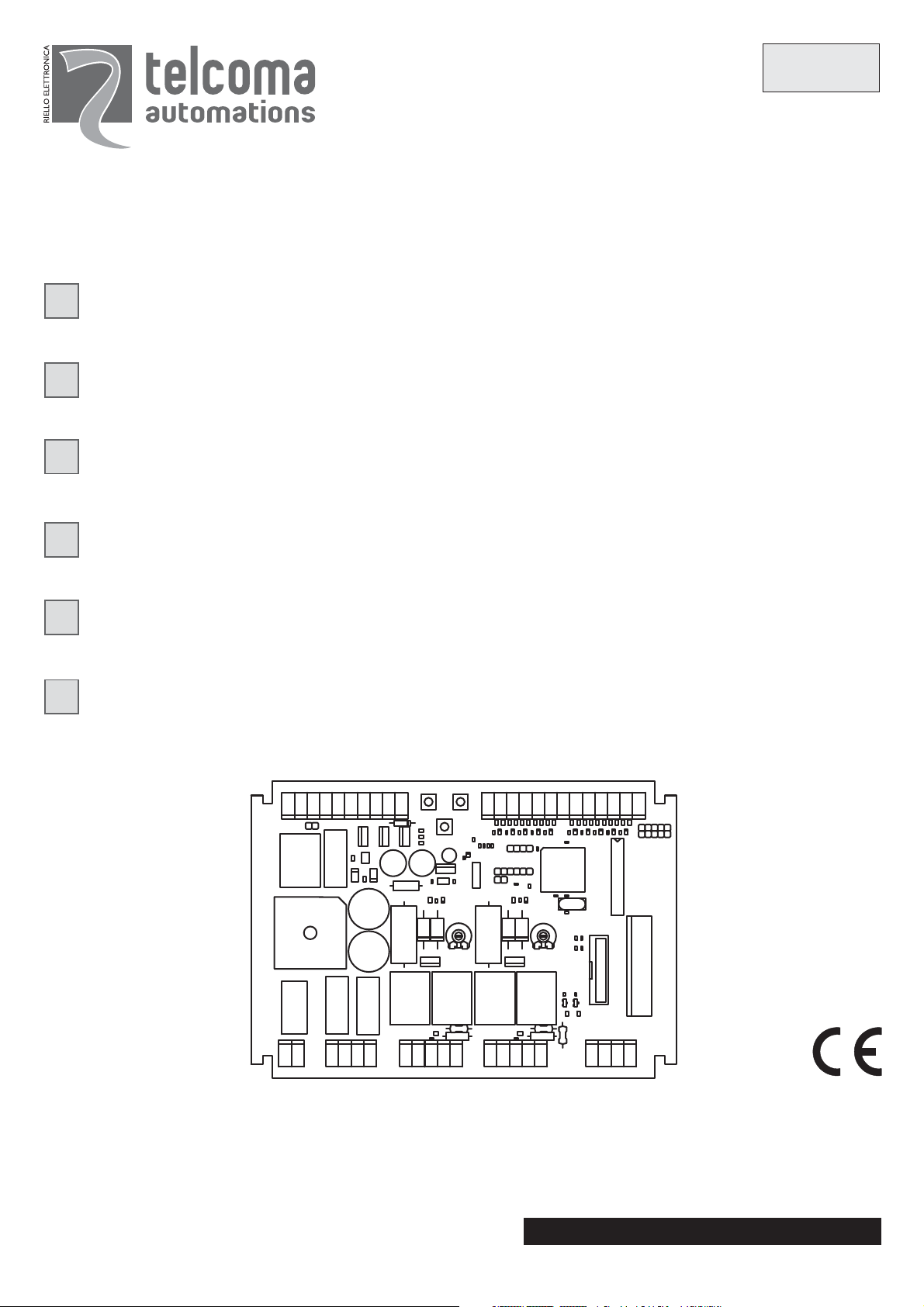
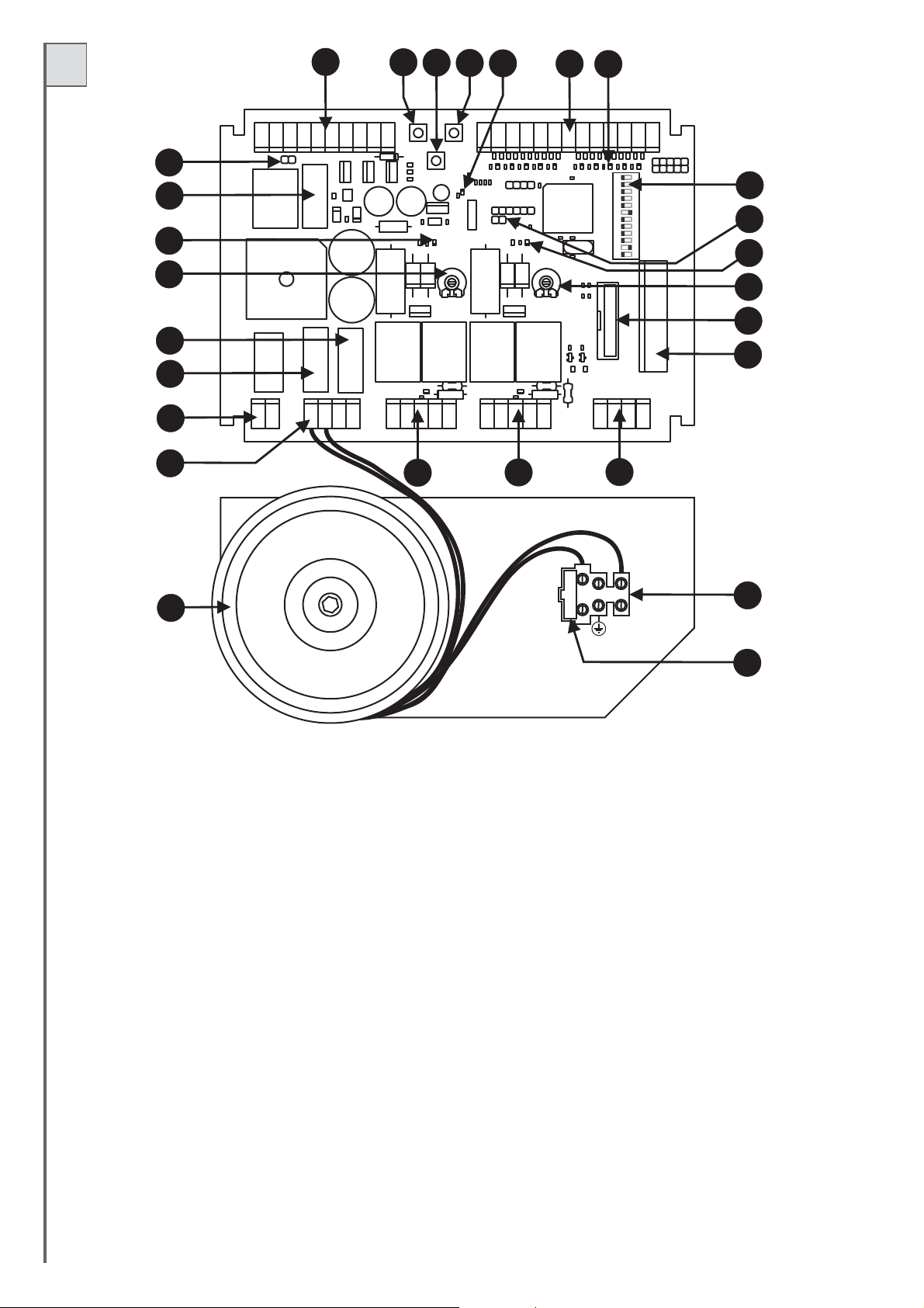
DESCRIZIONE DELLE PARTI (Fig. 1)
1 Fusibile linea 230V T2A (5x20 ritardato)
2 Morsettiera per collegamento linea alimentazione 230V
3 Trasformatore
4 Morsettiera per collegamento secondario trasformatore e caricabatteria (optional)
5 Morsettiera per collegamento luce cortesia (contatto pulito)
6 Fusibile bassa tensione 24V F16A (5x20)
7 Fusibile batteria/caricabatteria 24V T10A (5x20 ritardato)
8-22 Trimmer per regolazione potenza motori
9-21 Led funzionamento motori (LD1 e LD2)
10 Fusibile ausiliari 24V F5A (5x20)
11 Test fotocellule (vedi capitolo FOTO-TEST)
12 Morsettiera per collegamento: alimentazione ausiliari, spia cancello aperto e elettroserratura.
13 Pulsante per Programmazione e Stop*.
14 Pulsante P3 (programmazione tempo Pausa)
15 Pulsante Passo/Passo (P/P)
16 Led Programmazione (LD3)
17 Morsettiera per collegamento comandi e sicurezze
18 Led di segnalazione stato ingressi comando. Led acceso = ingresso chiuso; led spento = ingresso aperto
19 Dip-switch funzioni
20 Reset centralina (cortocircuitare per un attimo i 2 pin equivale a togliere e ridare alimentazione alla centralina)
23 Connettore per inserimento ricevitore a scheda modello OC (optional)
24 Connettore per inserimento ricevitore a scheda (optional)
25 Morsettiera per collegamento antenna e secondo canale del ricevitore radio
26-27 Morsettiere collegamento motori
1
* Questo pulsante di STOP ma solo di servizio per facilitare I test durante l’installazione.
3
non deve essere considerato di sicurezza
Page 4

I
INSTALLAZIONE
L'installazione dell'apparecchiaturadeve essereeffettuata a"REGOLA D'ARTE" dapersonale avente i requisiti richiesti dalle leggivigenti eseg
le normative EN12453eEN 12445riguardantila sicurezza dell'automazione.
-Accertarsiche l'automazione siadotatadi battute diarrestoe chequestesiano correttamente dimensionateperla massa delcancello.
- Fissare lacentralesu una superficiepianaed immobile, adeguatamenteprotettacontro gli urtiedallagamenti.
uendo
CARICA BATTERIA CB24 (opzionale)
Un impianto con T224 può funzionare anche in assenza di tensione di linea, questo è possibile inserendo due batterie ricaricabili da 12V 2,2Ah (non
fornite) e uncaricabatteriamod. CB24,iltutto senza modifichealresto dell'impianto.
Consigliamo, in impianti nuovi, il collegamento di batterie e carica batterie dopo il collaudato finale, di seguire la figura 2 e fare molta attenzione alla
polarità dei conduttori.
Sequenza di collegamento:
- togliere alimentazione230V
- collegare imorsetti3 e 4delCB24 con imorsetti28 e 29dellacentrale T224.
- collegare le2batterie(in serie)coni cavetti indotazioneai morsetti 1e2 del caricabatterie.
- verificare chelacentrale si alimenticorrettamente.
- ripristinare l'alimentazione230V.
Le batterie nuoveraggiungerannolacarica dopocirca10 ore.
Il numero dimanovreeseguibilicon alimentazioneabatteria dipende damoltifattori;
un esempio indicativopuòessere4 ciclicompletinelle seguenti condizioni:
- cancello 150Kgperanta
- impianto con2coppiedi fotocellule,riceventead innesto e1lampeggiante (20W max.)
- batterie cariche
- entro 5oredallamancanza linea230V
L
a centrale rallentaillampeggiodell’uscita lampeggiantenellaseguente condizione: funzionamentoabatteria con linea230Vassente.
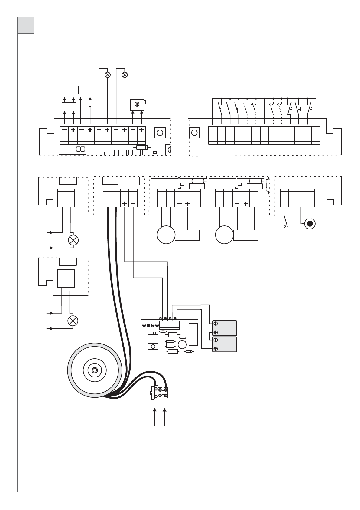
COLLEGAMENTI ELETTRICI
Per i collegamentiseguirela tabella 1ela figura 2.
Nel caso di impianti già esistenti e opportuno un controllo generale dello stato dei conduttori (sezione, isolamento, contatti) e delle apparecchiature
ausiliarie (fotocellule, riceventi,pulsantiere,selettori chiave, ecc.).
Elenchiamo alcuni consigliperun corretto impiantoelettrico:
- le conduttureentrantinelbox stagnodellacentralina devono essereinstallatemantenendo possibilmente invariatol'inizialegrado diprotezioneIP56.
- La sezionedeicavideve esserecalcolatain base allalorolunghezza e correntemassima.
- Non usareuncavounico deltipo"multi-polo" per tuttiicollegamenti (linea, motori,comandi,ecc.) oincomunecon altreapparecchiature.
- Dividere l'impiantoinalmeno due parti,ades.:
1) parte di potenza (linea alimentazione, motori, lampeggiante, luce cortesia, elettroserratura) sezione minima conduttori 1.5 mmq (linea motori
2,5mmq).
2) parte disegnale(comandi,contatti sicurezza,alimentazioneausiliari) sezione minimaconduttori0.75 mmq
- Quando icavidicomando presentanotrattemolto lunghe (oltrei50 metri) èconsigliabileil disaccoppiamentocondeirelè montativicinoalla centralina.
Tutti gli ingressiN.C.(normalmentechiuso) chenellacentralina non vengonoutilizzatidevono essere cortocircuitaticonil comune.
Tutti i contattiN.C.abbinatiad unostessoingresso devono esserecollegatiin serie.
Tutti i contattiN.A.(normalmenteaperto) abbinatiaduno stesso ingressodevonoessere collegati inparallelo.
Per l'alimentazione della centralina è previsto L'INSERIMENTO DI UN SEZIONATORE esterno (non in dotazione) indipendente e
dimensionato secondo ilcarico.
4
Page 5
I
24Vcc
Spia
cancello
Alimentazione
fotocellule
con Foto-test
(vedi testo)
24Vcc
24Vcc
Rx Tx
24Vcc
Aus.
11121231341451561671781891910
aperto
24Vcc
Lampeggiante
Elettro-
12Vcc
Serratura
COM.
COSTA APRE
C.AP
FT2
FT2
FT1
FT1
JOLLY 4
J4
JOLLY 3
J3
COM.
JOLLY 2
J2
PEDONALE
JOLLY 1
J1
PED.
STOP
STOP
P/P
P/P
COM.
24V
230V
24
24
25
25
24V
max. 50W
230V
max. 100W
26 27 28 29
30 3531 3632 3733 3834 39
DD
M1 M2
ENC 1 ENC 2
1234
12V 2,2Ah
20 21 22
40 41 42 43
Antenna*2°Ch
23
12V 2,2Ah
Fig.2
FUSE 5X20
44
45
230V
50/60 Hz
5
Page 6

Tab.1
I
Mor n. Mor n.
12
34
56
7
910
12 11
13
14
15 17
16 17
18 23
19
20
21
22
24
24
26 27
30
32
35
37
40
42
43
44
8
, 17, 23
11
, 17, 23
17
, 11, 23
, 11, 23
, 11, 23
, 17, 11
23
, 17, 11
23
, 17, 11
23
, 17, 11
23
, 17, 11
25
25
2928
31
33e34
36
38e39
41
45
Dispositivo
Ausiliari
Tx fotocellula/e
Spia
Lampeggiante
o lampadina
Elettroserratura
Contatto n.c.
Contatto n.c.
Contatto n.c.
Contatto
Contatto
Contatto
Contatto
Pulsante n.a.
Contatto n.c.
Pulsante n.a.
Lampada
Lampada
Trasformatore
CB24
Motore M1
Encoder M1
Motore M2
Encoder M2
Ausiliario
Antenna Rx*
Antenna Rx*
Linea
V Imax
24Vdc
1A
24Vdc 1A
24Vdc1A1A
24Vdc
12Vdc
1A
24V
2A
230Vac
0,5A
22Vac
6,8A
24Vdc
10A
24Vdc
5A
24Vdc
5A
max 24V 500mA
230Vac
2A
Funzione
Alimentazione
Permanente peralimentazione fotocellulee ricevitori esterni.
Alimentazione Tx per foto-test.
Cancello aperto
Indicatore di movimento
Durante le manovre con centrale alimentata solo a batterie
la frequenza di lampeggio diminuisce.
Blocco meccanico
Costa in apre
Fotocellula 2
Fotocellula 1
Jolly 4
Jolly 3
Jolly 2
Jolly 1
Pedonale
Stop
Passo/Passo
Luce di Cortesia
Luce di Cortesia
Alimentazione
Caricabatteria (optional)
Apre/Chiude
Sensore di movimento
Apre/Chiude
Sensore di movimento
Secondo canale Ricevitore
Calza
Centrale
Alimentazione centralina
Note
Se l’impianto prevede il funzionamento con Fototest collegare a
questa uscitasolo iricevitori (RX) dellefotocellule
Alimentazione per TX fotocellula (con funzione Fototest inserita)
Attiva da inizio manovra a cancello completamente chiuso.
Lampeggi differenziati in base allo stato del cancello:
cancello chiuso = spenta in apertura = lampeggio lento
in chiusura = lampeg. veloce in pausa = 2 lampeggi con pausa
cancello bloccato con pulsante stop = luce fissa
dopo un reset o mancanza rete la spia è spenta.
Lampeggio durante la manovra. L’accensione può essere
anticipata (prelampeggio)vedi dipswitch funzioni n.5.
L’uscita èlampeggiante quindi possiamo collegare una semplice
lampada a24V.
Attiva, per qualche secondo, ad ogni inizio apertura.
In apertura ferma il motore e chiude per qualche secondo.
Collegare questo ingresso al comune se non viene utilizzato.
In apertura blocco momentaneo, in chiude inverte la marcia.
Collegare questo ingresso al comune se non viene utilizzato.
Durante la chiusura inverte la marcia.
Collegare questo ingresso al comune se non viene utilizzato.
Vedi “modo ingressi Jolly” tab.2 (dip-switch n.3 e 4).
Vedi “modo ingressi Jolly” tab.2 (dip-switch n.3 e 4).
Vedi “modo ingressi Jolly” tab.2 (dip-switch n.3 e 4).
Vedi “modo ingressi Jolly” tab.2 (dip-switch n.3 e 4).
Vedi “modo ingressi Passo/Passo e Pedonale” tab.2 (dip-switch
n.1 e 2).
Blocco di tutte le funzioni.
Collegare questo ingresso al comune se non viene utilizzato.
Vedi dip-switch funzioni n.1 e n.2
Accesa da inizio manovra a 3 minuti dopo la chiusura completa.
Contatto da collegare come da schemi di fig.2
Accesa da inizio manovra a 3 minuti dopo la chiusura completa.
Contatto da collegare come da schemi di fig.2
Collegare questo ingresso al secondario del trasformatore
in dotazione (22V).
Predisposizione per il collegamento del caricabatteria CB24
(optional) e delle batterie (optional)
Il motore M1 viene ritardato in chiusura.
In impianti a battente il motore M1 comanda l’anta con l’elettro-serratura.
Sistema disponibile solo su alcune versioni di motore.
Rispettare le polarità mors. 32(-), mors. 33(+) e mors. 34(D).
Il motore M2 viene ritardato in apertura.
Sistema disponibile solo su alcune versioni di motore.
Rispettare le polarità mors. 37(-), mors. 38(+) e mors. 39(D).
Disponibile solo se viene inserita una scheda radio bicanale nel
connettore predisposto (particolare 24 di fig.1)
Nel caso venga collegata una ricevente al connettore
predisposto vedere le caratteristiche dell’antenna richieste dal
costruttore.
Collegare alla linea 230Vac. Vedi collegamenti elettrici.
Uscita
Ingresso
*ANTENNA: se viene usata una scheda radio ad innesto (tipo SR) prestare attenzione, in quanto, su alcuni modelli il connettore per il collegamento
dell’antenna è sulla scheda stessa.
6
Page 7
I
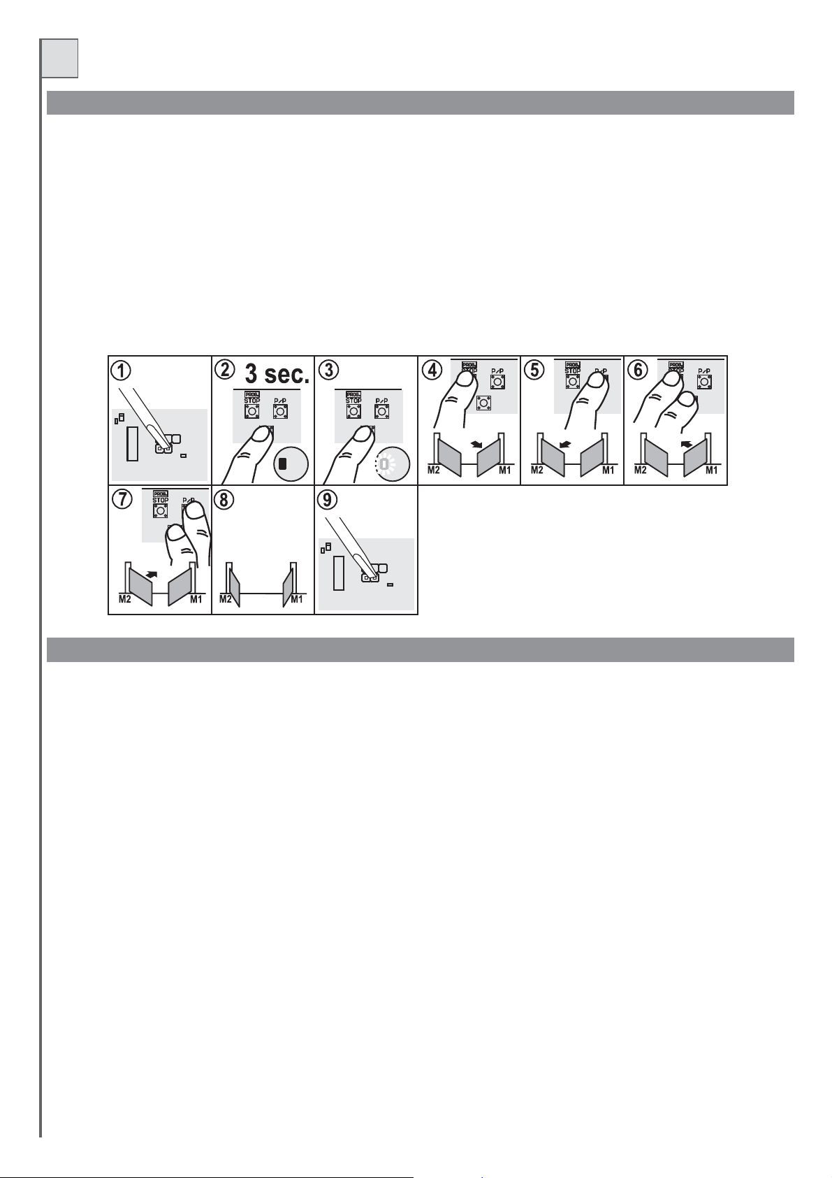
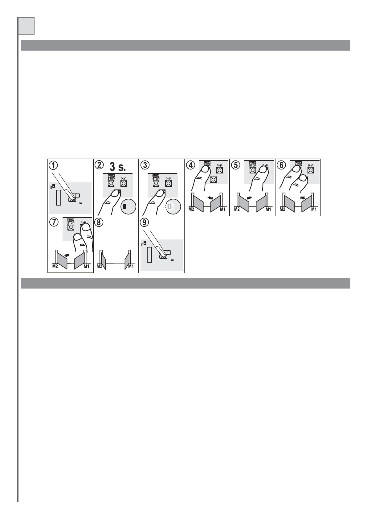
MANOVRA DI POSIZIONAMENTO MOTORI
Con questa procedura possiamo manovrare a piacere i motori collegati alla centrale, con lo scopo di preparare l’impianto per la programmazione
e per capire se i motori sono collegati correttamente.
Durantequesta operazioneipulsantifunzionano inmodo“uomo presente” elesicurezze vengono ignorate.
Procedura:
1- Fare unresetdellacentrale (cortocircuitandojumpReset part. 20difig. 1)
2- Premere iltastoP3(part. 14difig.1) per circa3secondi
3- Quando illedLD3(e illampeggiante)si accende rilasciareP3.Procedura attivata.
4- Premere iltastoPROGper aprireM1(se il motorechiudeinvertire il fili30con 31).
5- Premere iltastoP/Pper aprireM2 (seil motore chiudeinvertireil fili 35con36).
6- Premendo iltastoP3in contemporaneaconil tasto PROG il motore M1chiude.
7- Premendo iltastoP3in contemporaneaconil tasto P/P ilmotore M2 chiude.
8- Se l’operazionesuccessivaè una programmazione,p
spazio per muoversipercirca 5 secondiinchiusura.
9- Per tornarealfunzionamentonormale eseguireunreset della centrale(cortocircuitareil connettore, part.20di fig.1)
P3 P3
osizionare le ante(ola singola anta)in posizione dicancelloquasi aperto:leante devono avere
P3 P3 P3
Reset
P3
LD3 LD3
Reset
NOTE SULLA PROGRAMMAZIONE DEI TEMPI DI LAVORO E PAUSA
Procedura obbligatoria in nuove installazioni, lo scopo è quello di far memorizzare alla centrale i tempi di manovra e alcuni parametri utili per la
rilevazione degli ostacoli.
Sono disponibili duetipidi programmazione tempi:
- 1) programmazionetempiautomatica (semplificata)
- 2) programm
La scelta va fatta in base al tipo di automazione, la prima (automatica) ha dei parametri fissi come i tempi di ritardo anta (sfasamento) e il tempo di
rallentamento, con laseconda(manuale) possiamo registrareconprecisione la zonadisfasamento anta equelladi rallentamento.
- In casodidubbio consigliamo diiniziarecon laprogrammazioneautomatica e passareaquella manuale solosedurante ilfunzionamentole
ante entrano incontrasto.
- La programmazionemanuale diventa obbligatoriainimpianti asimmetricidovel’anta chedevechiudere per primaha un angolodi manovra
superioreall’altra anta.
Durante la fasediapprendimento si azioneràpiùvolte il tasto ( part.1 di fig 1),inalternativa sipuòusare il comando (morsetto 22,fig.2) oppure
il trasmettitore radiomemorizzatosul primo canaledelricevitore.
Noteimportanti primadellaprogrammazione:
- Negli impianticonelettroserratura,questa deveesseremontata nell'anta collegataalmotore M1.
-Alimentare lacentrale everificare il corretto funzionamento degli ingressi comando tramite i relativi Led(i contattiN.C. devonoavere ilLed acceso,in
contatti N.A. devonoavereilLed spento).
- Se i trasmettitori delle fotocellule sono alimentati conl'uscita per ilfoto-test (mors. 3e 4) verificarneil funzionamento cortocircuitandoil Jumper
(part. 11 difig.1).
- Scollegare lebatterieseutilizzate.
- Posizionare itrimmerdella sensibilità alcentroper avere unasensibilitàall'ostacolo media.
- Liberare lazonadimovimento delcancello.
- Eseguire l'autoapprendimentodeitempiscegliendo unadelleprogrammazioni descritte inseguito.
- Posizionare le ante (o la singolaanta) inposizione dicancello quasiaperto: le ante devono averespazio permuoversi percirca 5secondi inchiusura.
Se le antenonsonoin posizionesipuò usare laproceduradescritta nel paragrafoprecedente.
- Se sistausandoun solomotoreposizionare il dip11in OFF ecollegarloai morsetti motoreM1.
- Sesi trattadi unimpianto adue ante(scorrevoli obattenti chesiano) posizionareil dip11 inposizione ON.Il motorecollegato aimorsetti diM1 partirà
per primoin aperturae avràl'elettroserratura montatamentre ilmotore M2partirà perprimo inchiusura (questo ovviamente durante il funzionamento
normale, la proceduradiapprendimentoha unsuoordine di movimentimoltodiverso dal funzionamentoordinario).
7
azione tempi avanzata(manuale)
P/P 5 P/P
Test
Page 8
I
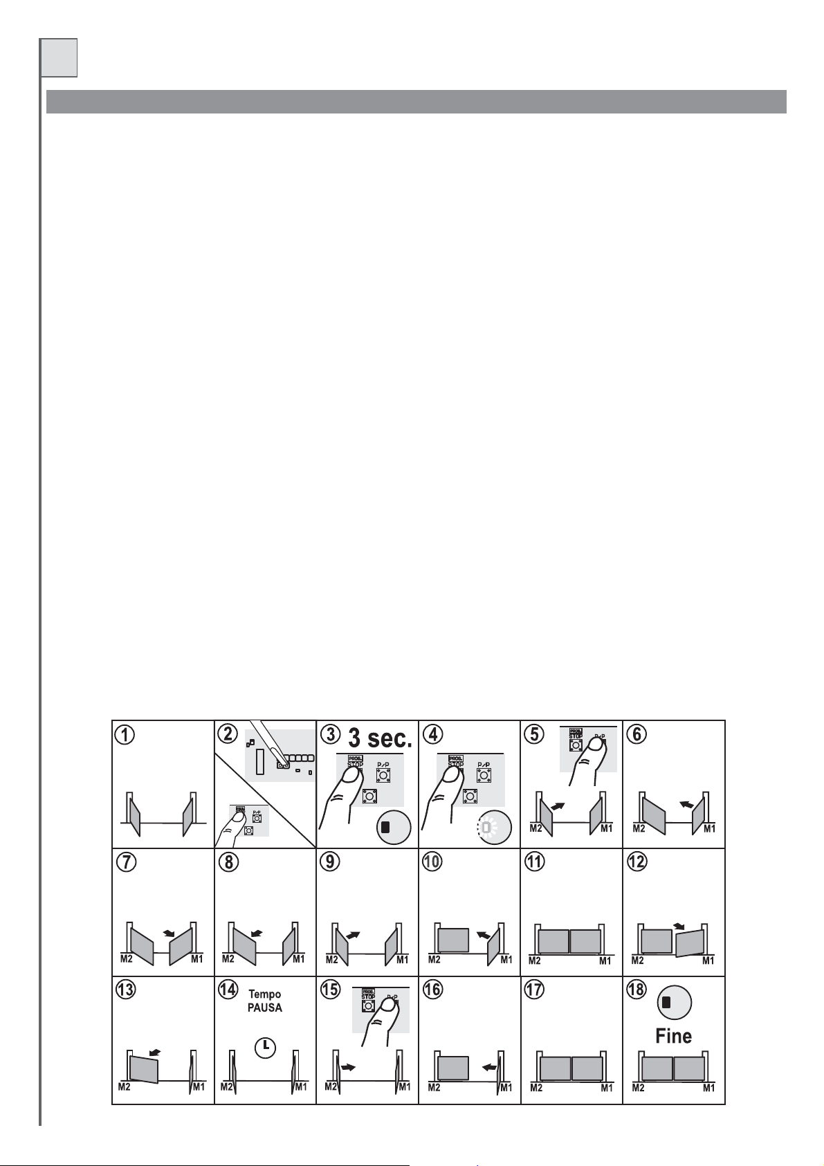
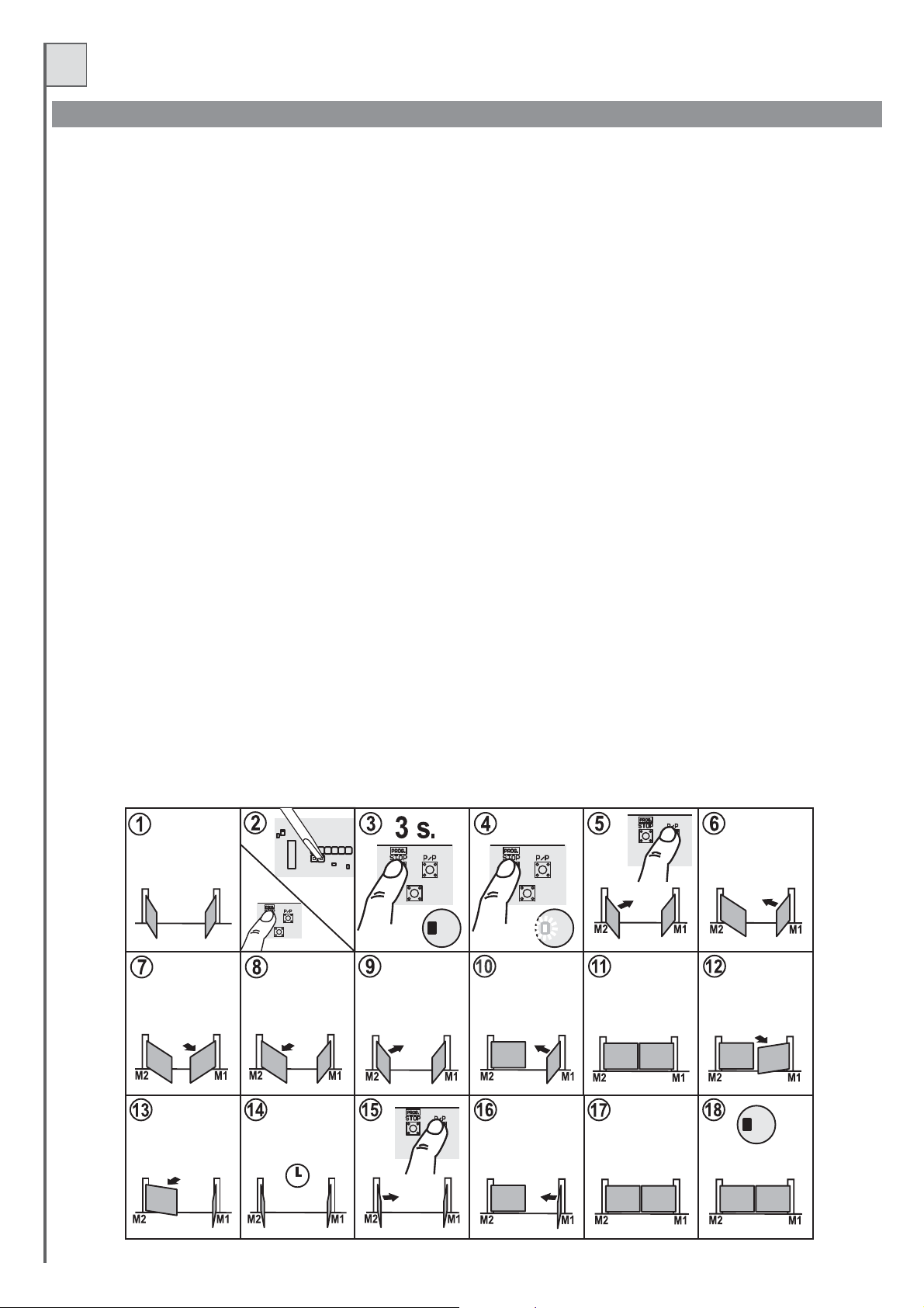
PROGRAMMAZIONE AUTOMATICA (semplificata)
Procedura:
1- posizionarele ante (o la singola anta) inposizione di cancello quasi aperto:le antedevono avere spazio per muoversiper circacinque secondi in
chiusura. Se leante non sonoinposizionesi puòusarela procedura descrittanelparagrafo precedente.
Tenendo premuto ilpulsanteProg effettuareun reset cortocircuitandocolcacciavite il jump .
23- Mantenere premutoilpulsanteProg.
4- Dopo tresecondiilled LD3 si accende.Attivata la proceduradiprogrammazione
(e il lampeggiante)
5- Premere ilpulsanteP/Pper avviarel'autoapprendimento. L’anta M2 parteinchiusura per 3-5sec(circa) e poisiferma
6-AntaM1 esegue subitodopolo stesso movimento.
IMPORTANTE: in questo movimento le ante non devono andare contro la battuta, ripetere l'autoapprendimento
(posizionando le anteinmodoche riescanoachiudere per 5secondisenza incontrare labattuta).
7-
Anta M1 parteinapreper 3-5sece si ferma.
8- Subito dopoanta2esegue lostessomovimento (3-5 secapree poi ferma).
IMPORTANTE: anche durante questo movimento le ante non devono andare contro la battuta, se succede questo posizionarle meglio e
ripetere l'autoapprendimento. A questo punto la centrale ha rilevato tutti i parametri delle due ante (presenza-assenza encoder e sua
velocità, corrente suimotori).
- La centrale rileva durante questa manovra la presenza degli encoder sui motori: NON E' AMMESSO avere un motore con l'encoder e
l'altrosenza ,seciò accade(adesempio per unguasto sull'encoder diunodei motori)lacentrale emette unsegnale di errorecostituitoda
dieci lampeggi suledLd3e lucespia.
-La correttarilevazione della presenza degli encoderpuò esserecontrollata guardando iled funzionamentomotori (part. 9 e 21di Fig. 1),
se il ledrelativoalmotore inmovimentolampeggia allora ilrispettivoencoder è statorilevato.
Seil ledrimaneaccesofisso alloral'encodernon è statorilevato.
-Se la centrale non vede encoder su entrambi i motori la rilevazione dell'ostacolo sarà effettuata monitorando la corrente durante il
funzionamento.
9- L’antaconM2 chiude completamente
10- Chiude ancheM1
11-12- Quando entrambileante sono chiuseparteautomaticamente in aperturaM1.
13- Quando M1èapertoapre completamenteancheM2.
14- Quando ledueantesono entrambeinposizione di aperturapartela memorizzazione deltempodi pausa.
15- Trascorso il tempo di pausa desiderato, premere il pulsante P/P, parte in chiusura il motore M2.
16- Quando M2 arriva in battuta, chiude M1.
17- Cancello completamente chiuso
18- Fine dellaprogrammazione(lacentrale sipredisponeautomaticamente per ilfunzionamentonormale).
- I valorimemorizzatirimangono inmemoriafinoalla prossimaprogrammazione.
- Questa procedurasemplificata di programmazione vaa impostare automaticamente ivalori dei ritardi anta e dei punti di rallentamento
utilizzando dei valorididefault.
- Qualora tali impostazioni dovessero rivelarsi inadatte all'installazione in oggetto sarà necessario procedere con la programmazione
avanzata descritta nelseguenteparagrafo.
Reset (part. 20difig.1)
se succede questo
P3
Reset
P3
8
P3 P3
LD3 LD3
P3
LD3
Page 9
I
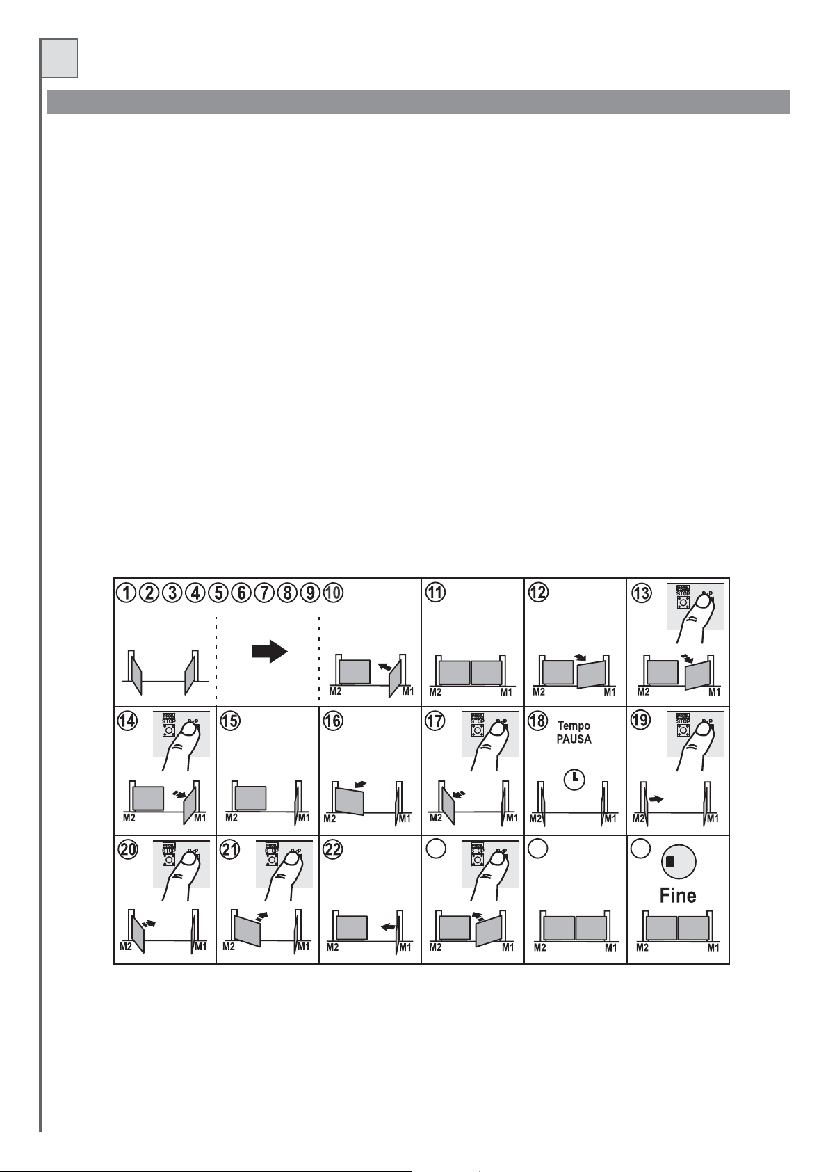
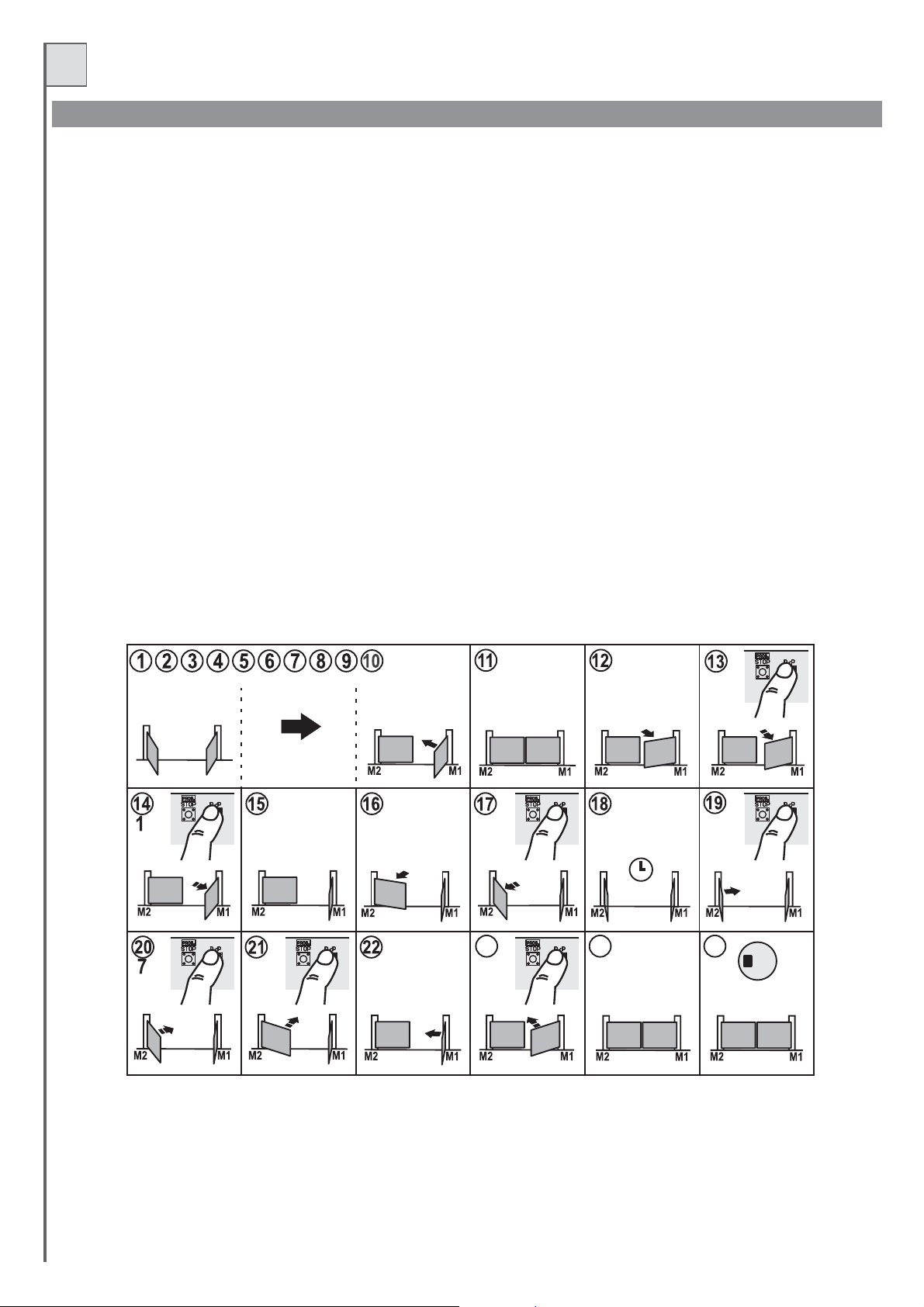
PROGRAMMAZIONE AVANZATA (manuale)
Questo tipo diprogrammazionepermettedi impostaremanualmentei ritardi antaei punti dirallentamento.
Procedura:
Seguire i puntida1a10delparagrafo precedente “Programmazioneautomatica”.
Procedere con le seguenti istruzioni considerando che, a differenza della programmazione automatica, in questa dobbiamo dare una sequenza di
riferimenti in temporeale.
11-12- Quando entrambileante sono chiuseparteautomaticamente in aperturaM1.
13- Premere il pulsante P/P quando le ante raggiungono lo sfasamento (di apertura) desiderato. Per evidenziare e confermare la registrazione il
motore M1 sifermaperun attimoeriparte in apertura.
14- Premere il pulsante P/P quando l’anta con M1 arriva nella zona (desiderata) di rallentamento. Per evidenziare e confermare la registrazione il
motore M1 sifermaperun attimoeriparte in apertura.
15-16- Quando M1arrivainbattuta (ofinecorsa)di apertura parteautomaticamenteM2 in apertura.
17- Premere il pulsante P/P quando l’anta con M2 arriva nella zona (desiderata) di rallentamento. Per evidenziare e confermare la registrazione il
motore M2 sifermaperun attimoeriparte in apertura.
18- Quando ledue ante sonoentrambeinposizione diaperturaparte la memorizzazionedeltempo di pausa.
19- Trascorsoil tempo dipausadesiderato, premere ilpulsanteP/P, parte inchiusurail motore M2.
20- Premere il pulsante P/P quando le ante raggiungono lo sfasamento (di chiusura) desiderato. Per evidenziare e confermare la registrazione il
motore M2 sifermaperun attimoeriparte in chiusura.
21- Premere il pulsante P/P quando l’anta con M2 arriva nella zona (desiderata) di rallentamento. Per evidenziare e confermare la registrazione il
motore M2 sifermaperun attimoeriparte in chiusura.
22- Quando M2arriva in battuta,chiudeM1.
23- Premere il pulsante P/P quando l’anta con M1 arriva nella zona (desiderata) di rallentamento. Per evidenziare e confermare la registrazione il
motore M1 sifermaperun attimoeriparte in chiusura.
24- Cancello completamentechiuso
25- Fine dellaprogrammazione(la centrale sipredisponeautomaticamente per ilfunzionamentonormale).
- I valorimemorizzatirimangonoin memoriafinoalla prossima programmazione.
P3 P3 P3
23 24 25
P3 P3
P3
LD3
P3
9
Page 10
I
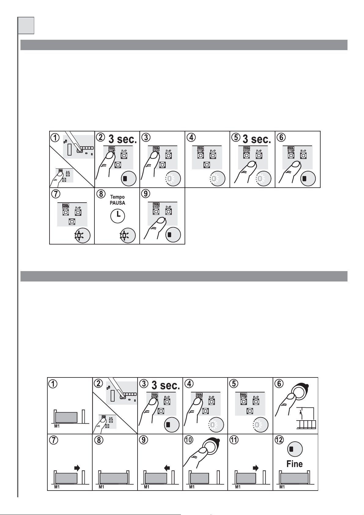
MODIFICA DEL TEMPO PAUSA
Il tempo dipausaviene memorizzato durantelaprogrammazione tempi. Permodificaresolo questo parametroprocederecome segue:
1-Tenendo premutoilpulsante Prog effettuare unresetcortocircuitando col cacciaviteiljump Reset(particolare20di fig.1).
2- Mantenere premutoilpulsanteProg.
3- Dopo tresecondiilled LD3 si accende.Attivata la proceduradiprogrammazione
4- Rilasciare ilpulsanteProg..
5-6 Mantenere premutoP3finoallo spegnimentodiLD3.
7- Rilasciare P3,illedLD3 lampeggiaeinizia la registrazionedeltempo di pausa.
8-Attendereil tempo desiderato
9- Premere ilpulsateP3per bloccareememorizzare il tempopausa.
Il led LD3sispegnee lacentraleesce dalla programmazione.
(e il lampeggiante)
Reset
P3
P3
LD3 LD3
P3 P3 P3
LD3 LD3 LD3
P3
LD3
P3
LD3
P3
LD3
MODIFICA DELL’APERTURA PEDONALE (modalità 1 motore)
- La programmazione del tempo pedonale funziona solo se la centrale è in modalità 1 motore (dip-switch 11 in OFF vedi part. 19 fig.1).
Procedura:
1- Bloccare il cancello leggermente aperto
2- Tenendo premuto il pulsante Prog effettuare un reset cortocircuitando col cacciavite il jump Reset (particolare 20 di fig.1).
3- Mantenere premutoilpulsanteProg.
4-5- Dopo tresecondiilled Ld3 si accende.Attivata la proceduradiprogrammazione
6-Aquestopunto (a differenza dellanormaleprogrammazione) dobbiamo premereilpulsante PED(pedonale) collegatoin morsettiera.
7- Il cancelloparteinchiusura etrovala battuta dichiusurao il finecorsa.
8-9- Quando e chiuso parte automaticamente in apertura
10- Quando il cancello raggiunge il punto di apertura (pedonale) desiderato premere nuovamente il pulsante Ped (pedonale).
11- Il cancello si ferma e poi chiude.
12- Il ledLD3sispegne elacentrale esce dallaprogrammazione.
(e il lampeggiante)
10
Ped
Reset
P3
P3 P3 P3
LD3 LD3 LD3
Ped
PED.
J1
PED.
19 20 21 22 23
LD3
P/P
COM.
STOP
Page 11
I
TAB.2
11
Page 12
I
FOTO TEST
Perché il foto test funzioni l'impianto deve prevedere due linee di alimentazione per le fotocellule, la prima collegata ai morsetti
ricevitori) la secondaaimorsetti 3 e4che alimenta itrasmettitori(il foto-test deveessereabilitato con ildip-switch n. 7inposizione ON).
La centrale controllal'efficienzadellefotocellule simulando uninterventoad ogni iniziomanovra.
Se tutto èOK partono imotori e iniziala manovra, seil ricevitore haqualche problema ilciclo si arrestae viene segnalatoda una seriedi lampeggi veloci
della spia cancelloapertoe di LD3.
La funzione fototest,oltrealfattore sicurezza,portai seguenti vantaggi:
- risparmio energetico(itrasmettitori delle fotocelluleacancello chiuso sonospenti)
- aumento dell'autonomianelcasodi alimentazioneabatterie
- minor usuradeicomponentidel trasmettitorefotocellula.
-
Il foto testfunzionaanchecon lafotocellula3 (ingresso Jolly).
- La centralinariconosceememorizza (durantelaprogrammazione dei tempi)quantee quali fotocellulesonostate collegate perilfototest.
- In impianti con il foto test, quando il cancello è chiuso, i trasmettitori delle fotocellule sono alimentati e gli ingressi sono aperti (led
spenti).
- Per ilcollaudodellefotocellule acancellochiuso cortocircuitare idueterminali “Test” (particolare11 di fig.1)presentisulla centrale.
- Le fotocelluleconcollegamentiper fototestfunzionano solo durantelamanovra.
non
1 e 2 (che alimenta i
SOFT START
È possibile modificare la fase di partenza dei motori per renderla più rapida.
Per modificare la partenza:
Con la centralina alimentata ed a cancello chiuso premere contemporaneamente i pulsanti STOP/PROG e P3 (part. 13 e 14 di fig. 1)
Dopo alcuni secondi si accende il led L3 (part. 16 di fig.1).
Se L3 rimane acceso con luce fissa, la partenza sarà più rapida.
Se L3 lampeggia la partenza sarà più graduale
Rilasciare i tasti per memorizzare l'impostazione.
Sulla T224, l'impostazione di fabbrica è con partenza graduale.
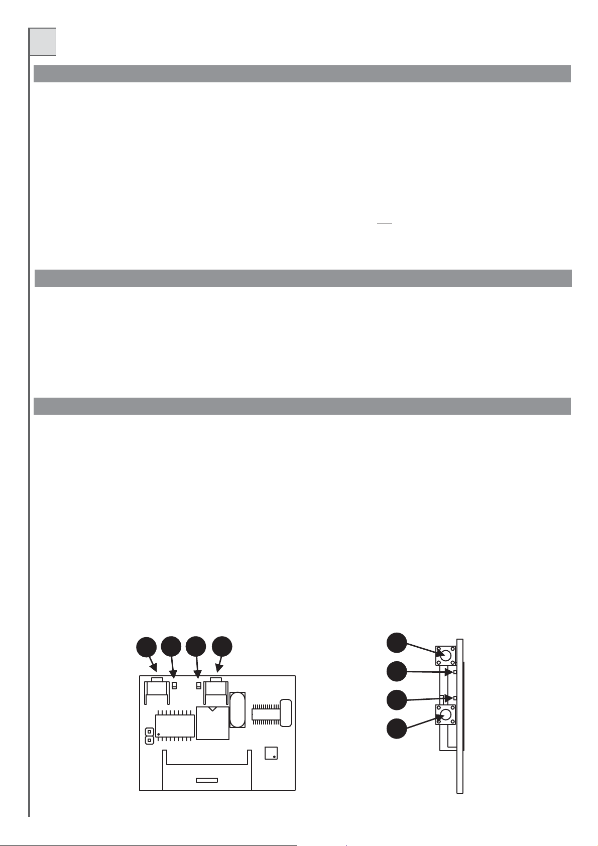
RICEVITORE AD INNESTO modello OC (opzionale)
Le riceventi sonoadauto-apprendimentoe possonomemorizzarepiù codici nellostessocanale.
Le funzioni deiduecanaliradio sono:
Canale 1 Passo/Passo
Canale 2 Pedonale
Per memorizzare itrasmettitoriprocedere come segue:
- Inserire lariceventenelconnettore (particolare23di fig. 1)
- Alimentare lacentraleeattendere cheiled sulla riceventesispengano.
- Sulla ricevente premere brevemente il pulsante del canale da memorizzare, (P1 passo/passo o P2 pedonale) il led corrispondente inizia a
lampeggiare.
Se il ledeseguedeilampeggi doppiattenderee ripetere l'operazione(iltastino deve esserepremutosolo unavolta).
-Trasmettereconil telecomando daprogrammare.
- Se illedsullaricevente esegueunlampeggio più lungovuoldire che lamemorizzazioneè andataabuonfine.
- Se ilcodiceegià presenteinmemoria, i leddellaricevente lampeggiano contemporaneamente.
È possibileresettare la memoria dei codicitenendo premuto il pulsante P1della ricevente per circa 15secondi sino a quando siaccendono entrambi i
led.
L'antenna va collegataaimorsetti 42 (calza)e43 (centrale) vedifig.2.
- Per ulterioriinformazioniespecifiche vedereilmanuale che accompagnalaricevente.
P1
Led1
Led2
P2
P1
Led1
12
Led2
MEMORIA
P2
Page 13
I
COLLAUDO FINALE
Eseguiresempre uncollaudofinale dopo averfattotutte le varieprogrammazioni.
- Controllare ilcorrettofunzionamentodei dispositividiprotezione (sistema antischiacciamento,pulsantestop, fotocellule, costesensibili,ecc.)
- Controllare ilcorrettofunzionamentodei dispositividisegnalazione (lampeggianti, spiacancelloaperto, ecc.).
- Controllare ilcorrettofunzionamentodei dispositividicomando (pulsante P/P, Radiocomandi,ecc.).
- Con il rallentamento abilitato e dopo un reset (o mancanza alimentazione) la centrale esegue una apertura a bassa velocità per cercare i
riferimenti(battute).
AVVERTENZE IMPORTANTI SULL’INSTALLAZIONE
L'installazione dell'automazione deve essere eseguita a regola d'arte da personale qualificato avente i requisiti di legge e fatta in conformità della
direttiva macchine 98/37/CEeallenormative EN13241-1,EN12453 e EN12445.
Verificare lasoliditàdelle strutture esistenti(colonne,cerniere, ante) inrelazionealle forze sviluppatedalmotore.
Verificare chevisiano dei fermimeccanicidi adeguata robustezzaafine apertura efinechiusura delleante.
Verificare lostatodi eventuali cavigiàpresenti nell'impianto.
Fare un'analisi deirischidell'automazione e diconseguenzaadottare le sicurezzeele segnalazioni necessarie.
Installare i comandi(adesempio il selettoreachiave) in modochel'utilizzatore non sitroviin unazonapericolosa.
Terminata l'installazione provarepiùvolte i dispositividi sicurezza, segnalazioneedi sblocco dell'automazione.
Applicare sull'automazione l'etichettaola targhetta CEcontenentile informazioni dipericoloe i datidiidentificazione.
Consegnare all'utilizzatore finaleleistruzioni d'uso, leavvertenzeper la sicurezzaela dichiarazione CEdiconformità.
Accertarsi che l'utilizzatoreabbiacompreso il correttofunzionamentoautomatico, manuale ediemergenza dell'automazione.
Informare l'utilizzatore periscritto(ad esempio nelleistruzionid'uso) :
- dell'eventuale presenzadirischi residui nonprotettie dell'uso improprioprevedibile.
- Di scollegarel'alimentazionequando viene eseguitalapulizia nell'area dell'automazioneoviene fatta piccolamanutenzione(es: ridipingere).
- Di controllarefrequentementechenon visianodanni visibili all'automazioneenel caso venesiano, avvertireimmediatamentel'installatore
- Di nonfargiocarei bambininelleimmediate vicinanze dell'automazione
Predisporre un pianodi manutenzionedell'impianto(almeno ogni6 mesi perle sicurezze) riportandosu diunapposito registrogli interventi
eseguiti.
SMALTIMENTO
Questo prodotto è formato da vari componenti che potrebbero a lorovolta conteneresostanze inquinanti.Non disperderenell'ambiente! Informarsisul
sistema di riciclaggioosmaltimento del prodottoattenendosialle norme dileggevigenti a livellolocale.
DICHIARAZIONE DI CONFORMITA’ CE
Il sottoscritto Augusto Silvio Brunello, Legale rappresentante della ditta:
TELCOMA S.r.l. Via Luigi Manzoni 11, 31015 Conegliano (TV) ITALY
Dichiara che il prodotto:
Modello con impiego: Centralina per apricancello
È conforme ai requisiti essenziali dell'articolo 3 ed ai relativi provvedimenti della Direttiva 1999/5/CE, se impiegato per gli usi preposti.
E' conforme ai requisiti essenziali Direttiva 89/336 (EMC) norme EN 61000-6-3, EN 61000-6-1 e successive modifiche, se impiegato per gli usi
preposti.
E' conforme ai requisiti essenziali Direttiva 73/23 (LVD) norme EN 60335-1 e successive modifiche, se impiegato per gli usi preposti.
Luogo e data:
Conegliano, 21/07/2006
T224
Legale rappresentante
Augusto Silvio Brunello
13
Page 14

F
INSTRUCTIONS POUR L'INSTALLATION ET LA PROGRAMMATION
- Ce livretestdestinéau personneltechniquequalifié pour lesinstallations.
- Avant d'effectuer l'installation nousconseillonsde lire attentivementcesinstructions.
- Une utilisation impropre du produit ou une erreur de connexion pourrait compromettre le fonctionnement correct de ce dernier et la sécurité de
l'utilisateur final.
CARACTÉRISTIQUES
Cette logique de commande peut automatiser :
- portails à deux vantaux avec ou sans fin de course
- portails à un vantail avec ou sans fin de course
- portails à deux vantaux coulissants avec fin de course
- portails à un vantail coulissant avec fin de course
La logique de commande est munie de :
- contrôle moteur à encodeur et/ou ampèremétrique
- ralentissement moteur programmable
- soft start
- contrôle fonctionnement photocellule (Photo Test)
- autodiagnostic du pilotage moteurs (MOSFET)
- connecteurs pour récepteurs OC et/ou récepteurs CARTE
DONNÉES TECHNIQUES
P
aramètres électriques U.M. T224
Alimentation Vca 230 ±10%
Fréquence Hz 50/60
Absorption stand-by (230V) mA 18 / 25 min / max
Absorption maximum (230V) A 2
Puissance max. moteurs 24V VA 360 (2X180)
Température de fonctionnement °C -20 +60
Dimension coffret (L x H x P) mm 220x280x120
14
Page 15
F
12
13
14
15
16
17
18
11
10
9
8
7
1
2
3
4
5
ON
6
7
8
9
10
ON
11
ON
M1
M2
12
19
20
21
22
23
24
6
5
4
6
27
26
25
2
3
FUSE 5X20
Fig.1
1
DESCRIPTION DES PARTIES (Fig. 1)
1 Fusible ligne 230 V T2A (5x20 retardé)
2 Bornier pour connexion photocellule ligne d'alimentation 230 V
3 Transformateur
4 Bornier pour connexion secondaire transformateur et chargeur de batterie (option)
5 Bornier pour connexion éclairage automatique (contact N.O.)
6 Fusible basse tension 24 V F16 A(5x20)
7 Fusible batterie/chargeur de batterie 24 V T10A (5x20 retardé)
8-22 Trimmer pour réglage puissance moteurs
9-21 Leds fonctionnement moteurs (LD1 et LD2)
10 Fusible auxiliaires 24 V F5A (5x20)
11 Test photocellules (voir chapitre PHOTO-TEST)
12 Bornier pour connexion : alimentation auxiliaires, voyant portail ouvert et serrure électrique.
13 Touche pour Programmation et Stop*.
14 Touche P3 (programmation temps de Pause)
15 Touche Pas à pas (P/P)
16 Led Programmation (LD3)
17 Bornier pour connexion commandes et sécurités
18 Led de signalisation état entrées commande. Led allumée = entrée fermée ; led éteinte = entrée ouverte
19 Dip-switch fonctions
20 Réinitialisation de la logique (court-circuiter un instant les 2 broches équivaut à enlever et à redonner l'alimentation à la logique)
23 Connecteur pour branchement du récepteur sur carte électronique modèle OC (option)
24 Connecteur pour branchement du récepteur sur carte (option)
25 Bornier pour connexion antenne suivant canal du récepteur radio
26-27 Borniers pour connexion moteurs
* Cette touche de STOP mais seulement comme une touche de service pour faciliter les tests
ne doit pas être considérée comme une sécurité
durant l'installation.
15
Page 16

F
INSTALLATION
L'installation de l'appareil doit être effectuée DANS LES RÈGLES DE L'ART par du personnel ayant les caractéristiques requises par les lois en
vigueur et conformément aux normes EN 12453 et EN 12445 concernant la sécurité de l'automatisation.
- Contrôler que l'automatisation est munie de butées d'arrêt et que celles-ci sont correctement dimensionnées pour la masse du portail.
- Fixer la logique de commande sur une surface plane et immobile, protégée de manière adéquate contre les chocs et les inondations.
CHARGEUR DE BATTERIE CB24 (option)
Une installation avec T224 peut fonctionner également en cas de manque de tension de secteur, en ajoutant deux batteries rechargeables de 12
V 2,2 Ah (non fournies) et un chargeur de batterie mod. CB24, le tout sans modifier le reste de l'installation.
Dans les installations neuves, nous conseillons de connecter les batteries et le chargeur de batteries après l'essai final en suivant la figure 2 et en
faisant attention à la polarité des conducteurs.
Séquence de connexion :
- couper l'alimentation 230 V
- connecter les bornes 3 et 4 du CB24 aux bornes 28 et 29 de la logique T224
- connecter les 2 batteries (en série) avec les câbles fournis aux bornes 1 et 2 du chargeur de batterie
- vérifier que la logique de commande s'alimente correctement
- rétablir l'alimentation 230 V.
- Les batteries neuves seront rechargées au bout d'environ 10 heures.
- Le nombre de manœuvres exécutables avec l'alimentation à batterie dépend de nombreux facteurs ;
un exemple indicatif peut être 4 cycles complets dans les conditions suivantes :
- portail 150 kg par vantail
- installation avec 2 paires de photocellules, récepteur embrochable et 1 clignotant (20 W max.)
- batteries rechargées
- dans les 5 heures qui suivent le manque de courant 230 V
- La logique de commande ralentit le clignotement de la sortie du clignotant dans la condition suivante : fonctionnement par batterie
avec ligne 230V absente.
BRANCHEMENTS ÉLECTRIQUES
Pour les connexions suivre le tableau 1 et la figure 2.
Dans le cas d'installations pré-existantes il est opportun d'effectuer un contrôle général de l'état des conducteurs (section, isolement, contacts) et
des appareils auxiliaires (photocellules, récepteurs, claviers de commande, sélecteurs à clé, etc.).
Voici quelques conseils pour une installation électrique correcte :
- les canalisations entrant dans le coffret étanche de la logique de commande doivent être installées sans compromettre si possible le degré de
protection IP56.
- La section des câbles doit être calculée suivant leur longueur et le courant maximum.
- Ne pas utiliser un câble unique du type « multipolaire » pour toutes les connexions (secteur, moteurs, commandes, etc.) ou en commun avec
d'autres appareils.
- Diviser l'installation en au moins deux parties, par ex.:
1) partie de puissance (ligne d'alimentation, moteurs, clignotant, éclairage automatique, serrure électrique) section minimum conducteurs 1,5 mm²
(ligne moteurs 2,5 mm²)
2) partie de signal (commandes, contacts de sécurité, alimentation auxiliaires) section minimum conducteurs 0,75 mm²
- Quand les câbles de commande présentent de très longs tronçons (plus de 50 mètres) il est conseillé de procéder à un découplage avec des
relais montés près de la logique de commande.
· Toutes les entrées N.F. (normalement fermé) qui ne sont pas utilisées dans la logique de commande doivent être court-circuitées avec
le commun.
- Tous les contacts N.F. associés à une même entrée doivent être connectés en série.
- Tous les contacts N.O.(normalement ouvert) associés à une même entrée doivent être connectés en parallèle.
- Pour l'alimentation de la logique, on prévoit le MONTAGE D'UN SECTIONNEUR extérieur (non fourni) indépendant et dimensionné
suivant la charge.
16
Page 17

F
24 Vcc
Voyant
portail ouvert
24Vcc
24Vcc
Alimentation
Photocellules
avec Photo-test
(voir texte)
24Vcc
Rx Tx
Aux.
11121231341451561671781891910
24Vcc
Clignotant
Serrure
électrique
12Vcc
BARRE PALPEUSE OUVERTURE
C.AP
COM.
PHOTOCELL. 2
FT2
PHOTOCELL. 1
FT1
JOLLY 4
J4
JOLLY 3
J3
COM.
JOLLY 2
J2
JOLLY 1
J1
PIÉTON
PED.
STOP
STOP
P/P
P/P
COM.
24V
230V
24
24
25
25
24V
max. 50W
230V
max. 100W
26 27 28 29
30 3531 3632 3733 3834 39
DD
M1 M2
ENC 1 ENC 2
1234
12V 2,2Ah
20 21 22
40 41 42 43
2e canal antenne
23
17
Fig.2
FUSE 5X20
44
45
230V
50/60 Hz
12V 2,2Ah
Page 18

F
Tab.1
Borne n. Borne n.
12
34
56
7
8
910
11
17
23
23
23
23
25
25
, 17, 23
, 17, 23
, 11, 23
, 11, 23
, 11, 23
, 17, 11
, 17, 11
, 17, 11
, 17, 11
, 17, 11
12 11
13
14
15 17
16 17
18 23
19
20
21
22
24
24
26 27
2928
30
32
35
37
40
31
33e34
36
38e39
41
42
43
44
45
Dispositiv
Auxiliaires
Tx photocellules
Voyant
Clignotant
ou ampoule
Serrure électrique
Contact N.F.
Contact N.F.
Contact N.F.
Contact
Contact
Contact
Contact
Touche N.O.
Contact N.F.
Touche N.O.
Ampoule
Ampoule
Transformateur
Cb24
Moteur M1
Encodeur M1
Moteur M2
Encodeur M2
Auxiliaire
Antenne Rx*
Antenne Rx*
Ligne
V Imax
24Vdc
1A
24Vdc 1A
24Vdc1A1A
24Vdc
12Vdc
1A
24V
2A
230Vac
0,5A
22Vac
6,8A
24Vdc
10A
24Vdc
5A
24Vdc
5A
max 24V 500mA
230Vac
2A
Fonction
Alimentation
Alimentation Tx pour photo-test.
Portail ouvert
Indicateur de mouvement
Durant les manœuvres avec logique alimentée uniquement
par batteries la fréquence de clignotement diminue
Blocage mécanique
Barre palpeuse en ouverture
Photocellule 2
Photocellule 1
Jolly 4
Jolly 3
Jolly 2
Jolly 1
Piéton
Stop
Pas à pas
Éclairage automatique
Éclairage automatique
Alimentation
Chargeur de batterie (option)
Ouverture/fermeture
Capteur de mouvement
Ouverture/fermeture
Capteur de mouvement
Deuxième canal récepteur
Conducteur externe
Âme
Alimentation logique de commande
Permanente pouralimentation photocelluleset récepteurs externes.
Notes
Si l'installation prévoit le fonctionnement avec phototest connecter à cette
sortie uniquementles récepteurs(RX) des photocellules
Alimentation pour TX photocellule (avec fonction Phototest incorporée) Active
du début de la manœuvre jusqu'à ce que le portail soit complètement fermé.
Clignotements différenciés suivant l'état du portail :
portail fermé = éteint en ouverture = clignotement lent
en fermeture = clignotement rapide en pause = 2 clignotements avec pause
portail bloqué par touche stop = lumière fixe
après une réinitialisation ou une coupure d'alimentation le voyant est éteint
Clignotement durant la manœuvre. L'allumage peut être anticipé
(préclignotement) voirdip switchfonctions n.5.
La sortieest clignotanteon peut doncconnecter unesimple ampoule à24V.
Active, pendant quelques secondes, à chaque début d'ouverture.
En ouverture arrête le moteur et ferme pendant quelques secondes.
Connecter cette entrée au commun si elle n'est pas utilisée.
En ouverture blocage momentané, en fermeture, inversion du mouvement.
Connecter cette entrée au commun si elle n'est pas utilisée.
Durant la fermeture inversion du mouvement.
Connecter cette entrée au commun si elle n'est pas utilisée.
Voir « mode entrées Jolly » tab.2 (dip-switch n.3 et 4).
Voir « mode entrées Jolly » tab.2 (dip-switch n.3 et 4).
Voir « mode entrées Jolly » tab.2 (dip-switch n.3 et 4).
Voir « mode entrées Jolly » tab.2 (dip-switch n.3 et 4).
Voir « mode entrées Pas à pas et Piéton » tab.2 (dip-switch n.1 et 2).
Blocage de toutes les fonctions.
Connecter cette entrée au commun si elle n'est pas utilisée.
Voir dip-switch fonctions n.1 et n.2
Allumée du début de la manœuvre jusqu'à 3 minutes après la fermeture
complète.
Allumée du début de la manœuvre jusqu'à 3 minutes après la fermeture
complète.
Connecter cette entrée au secondaire du transformateur fourni (22 V).
Prévision pour la connexion du chargeur de batterie CB24 (option) et des
batteries (option)
Le moteur M1 est retardé en fermeture. Dans les installations à vantaux
battants le moteur M1 commande le vantail avec la serrure électrique.
Système disponible seulement sur certaines versions de moteur.
Respecter les polarités borne 32(-), borne 33(+) et borne 34(D).
Le moteur M2 est retardé en ouverture.
Système disponible seulement sur certaines versions de moteur.
Respecter les polarités borne 37(-), borne 38(+) et borne 39(D).
Disponible seulement si une carte électronique radio bicanal est branchée
dans le connecteur prévu à cet effet (pos. 24 fig.1)
Si un récepteur est connecté au connecteur prévu, voir les caractéristiques
de l'antenne requises par le constructeur
Connecter à la ligne 230 Vca. Voir branchements électriques.
Sortie
Entrée
*ANTENNE : si on utilise une carte électronique radio embrochable (type SR) faire attention, dans la mesure où, sur certains modèles, le connecteur pour
la connexion de l'antenne se trouve sur la carte électronique proprement dite.
18
Page 19
F
MANŒUVRE DE POSITIONNEMENT MOTEURS
Avec cette procédure onpeut manœuvrerà volonté les moteurs connectés à lalogique, dansle but de préparer l'installation pour laprogrammation et
pour comprendre silesmoteurs sont connectéscorrectement.
- Durant cetteopérationlestouches fonctionnentenmode « commandeàaction maintenue »etles sécurités sontsouventignorées.
Procédure:
1- Réinitialiser lalogiquede commande (encourt-circuitantle cavalier Resetpos.20 fig. 1)
2- Presser latoucheP3(pos. 14fig.1) pendant environ3secondes.
3- Quand laledLD3(et leclignotant)s'allume relâcher P3.Laprocédure est activée.
4- Presser latouchePROGpour ouvrirM1(si le moteurfermeinverser le fils30avec le31).
5- Presser latoucheP/Ppour ouvrirM2 (sile moteur fermeinverserle fil 35avecle 36).
6- En pressantlatoucheP3 enmêmetemps que latouchePROG lemoteur M1ferme.
7- En pressantlatoucheP3 enmêmetemps que latoucheP/Ple moteurM2ferme.
8- Si l'opération successive est une programmation, positionner les vantaux (ou chaque vantail) en position de portail presque ouvert : les vantaux
doivent avoir delaplace pour bougerpendantenviron 5 secondesenfermeture.
9- Pour revenir au fonctionnement normal effectuer un réarmement de la logique de commande (court-circuiter le connecteur, pos. 20 fig.1)
P3 P3 P3
P3 P3
Reset
P3
LD3 LD3
Reset
NOTES SUR LA PROGRAMMATION DES TEMPS DE TRAVAIL ET DE PAUSE
Procédure obligatoire dans les nouvelles installations, le but est de faire mémoriser à la logique les tempsde manœuvre etcertains paramètres utile
pour la détectiondesobstacles.
On peut choisirentredeuxtypes deprogrammationdes temps :
- 1) programmationautomatiquedestemps (simplifiée)
- 2) programmation manuelle) des temps
Le choix doitêtre faitsuivantle typed'automatisme, lapremière(automatique) adesparamètres fixescomme lestempsde retarddu vantail (décalage)etle
tempsde ralentissement, avecladeuxième(manuelle)nous pouvonsenregistreravecprécisionla zone dedécalagevantailet celle deralentissement.
- En casde doute,nous conseillonsde commencer parla programmationautomatique etde passer àla programmationmanuelle seulement
si les vantauxprésententundécalage erronédurantle fonctionnement.
- La programmationmanuelle devient obligatoiredans les installationsasymétriques où levantail qui doitse fermer enpremier aunangle de
manœuvresupérieur àl'autrevantail.
Durant la phased'apprentissageon actionnera plusieursfoisla touche P/P(pos.15 fig. 1),enalternative onpeututiliser la commandeP/P(borne 22, fig.
2) ou l'émetteurradiomémorisésur lepremiercanal du récepteur.
Notesimportantes avantlaprogrammation:
- Dans lesinstallationsavec serrure électrique,celle-cidoit être montéesurle vantail connectéaumoteur M1.
- Alimenter la logique de commande et vérifier le fonctionnement correct des entrées de commande et des leds correspondantes (les contacts N.F.
doivent avoir laledallumée, les contactsN.O.doivent avoir laledéteinte).
- Si lesémetteurs des photocellules sono alimentés avec lasortie pour le photo-test (bornes 3 et4) en vérifier le fonctionnement en court-circuitantle
cavalierTest (pos.11 fig.1).
- Déconnecter lesbatteriessielles sontutilisées.
- Positionner lestrimmersde la sensibilitéaucentre pour avoirunesensibilité moyenne àl'obstacle.
- Libérer lazonedemouvement duportail.
- Effectuer l'auto-apprentissage destempsen choisissant unedesprogrammations décrites ci-après.
- Positionner les vantaux (ou le vantail) en position de portail presque ouvert : les vantaux doivent avoir de la place pour bouger pendant environ 5
secondes en fermeture.Silesvantaux nesontpas en positiononpeut utiliser laprocéduredécrite auparagraphe précédent.
- Si onn'utilisequ'unseul moteurpositionnerle dip 11 surOFFet le connecterauxbornes moteur M1.
- S'il s'agit d'une installation à deux vantaux (qu'ils soient coulissants oubattants) positionner ledip 11 sur ON. Lemoteur connecté auxbornes de M1
partira en premier en ouvertureet aurala serrureélectrique montée tandis que lemoteur M2partira enpremier en fermeture(cela évidemmentdurant
le fonctionnement normal,laprocédured'apprentissage aunordre de mouvementstrèsdifférentdu fonctionnement ordinaire).
avancée (
s
19
Page 20
F
PROGRAMMATION AUTOMATIQUE (simplifiée)
Procédure :
1- Positionner les vantaux (ou le vantail) en position de portail presque ouvert : les vantaux doivent avoir de la place pour bouger pendant environ 5
secondes en fermeture. Si les vantauxnesontpas enpositionon peut utiliserlaprocédure décrite auparagrapheprécédent.
2- En maintenantlatoucheProg enfoncée,effectueruneréinitialisation en court-circuitantavecun tournevis lecavalierReset (pos.20fig.1).
3- Maintenir latoucheProgenfoncée.
4-Aubout de troissecondes,la led LD3(etle clignotant)s'allume.Laprocédure deprogrammationest activée.
5- Presser latoucheP/Ppour lancerl'auto-apprentissage. Levantail M2 partenfermeture pendant 3-5sec(environ) puis s'arrête
6- Le vantailM1exécutejuste aprèslemême mouvement.
IMPORTANT: dans ce mouvement, les vantaux ne doivent pas aller contre la butée, si cela se produit, répéter l'auto-apprentissage (en
positionnant les vantauxdemanièrequ'ils parviennentàfermer pendant 5secondessans rencontrer labutée).
7- Le vantailM1parten ouverturependant3-5 s puiss'arrête.
8- Juste après,levantail2 effectue lemêmemouvement (3-5 sd'ouverturepuis arrêt).
IMPORTANT: durantcemouvement nonplus les vantauxne doivent pasfinir contre labutée, sicelase produit,lespositionner correctement
et répéter l'auto-apprentissage. À ce point la logique de commande a détecté tous les paramètres des deux vantaux (présence-absence
encodeuret savitesse,courantsur lesmoteurs).
- La logiquede commandedétecte aucours de cette manœuvre laprésence desencodeurs sur lesmoteurs :IL N'EST PAS ADMISd'avoir un
moteur avecl'encodeur etl'autre sans,si cela se produit (par exemple à cause d'unepanne surl'encodeur d'undes moteurs)la logique de
commande émet unsignald'erreurconstitué dedixclignotements sur ledLD3et voyant.
- La détection correctede la présence des encodeurspeut être contrôlée en regardantles leds du fonctionnement moteurs (pos. 9et 21
Fig. 1), sila led correspondantau moteur enmouvementclignote, l'encodeurcorrespondanta été détecté.
Sila ledrestealluméefixe, l'encodeurn'apas été détectée.
- Si lalogique decommande ne voitpas l'encodeursur les deuxmoteurs ladétection del'obstacle sera effectuéeen contrôlantle courant au
coursdu fonctionnement.
9- Le vantailavecM2ferme complètement
10- Le vantailavecM1ferme luiaussi
11-12- Quand lesdeuxvantaux sont fermés,M1part automatiquement enouverture.
13- Quand M1estouvertM2 ouvrecomplètementlui aussi.
14- Quand lesdeuxvantauxsont enpositiond'ouverture la mémorisationdutemps de pausedémarre.
15- Quand letempsdepause désirés'estécoulé, presser latoucheP/P, le moteurM2part en fermeture.
16- Quand M2arriveenbutée, M1ferme.
17- Portail complètementfermé
18- Fin delaprogrammation(la logiquedecommande se prépareautomatiquementau fonctionnement normal).
- Les valeursmémoriséesrestenten mémoirejusqu'àla prochaine programmation.
- Cette procédure simplifiée de programmation configure automatiquement les valeurs des retards des vantaux et des points de
ralentissementen utilisantdesvaleurspar défaut.
- Si ces paramètres serévèlent inadaptés àl'installation en objet, il faudra procéder avec laprogrammation avancée décriteau paragraphe
qui suit.
20
P3
Temps
PAUSE
Reset
P3 P3
LD3 LD3
P3
P3
LD3
Fin
Page 21
F
PROGRAMMATION AVANCÉE (manuelle)
Ce type de programmation permet de configurer manuellement les retards des vantaux et les points de ralentissement.
Procédure :
Suivre les points de 1 à 10 du paragraphe précédent « Programmation automatique ».
Procéder avec les instructions qui suivent en considérant que, contrairement à la programmation automatique, dans celle-ci nous devons donner
une séquence de références en temps réel.
11-12- Quand les deux vantaux sont fermés, M1 part automatiquement en ouverture.
13- Presser la touche P/P quand les vantaux atteignent le décalage (d'ouverture) désiré. Pour mettre en évidence et confirmer le réglage, le
moteur M1 s'arrête un instant et repart en ouverture.
14- Presser la touche P/P quand le vantail avec M1 arrive dans la zone (désirée) de ralentissement. Pour mettre en évidence et confirmer le
réglage, le moteur M1 s'arrête un instant et repart en ouverture.
15-16- Quand M1 arrive en butée (ou fin de course) d'ouverture, M2 part automatiquement en ouverture.
17- Presser la touche P/P quand le vantail avec M2 arrive dans la zone (désirée) de ralentissement. Pour mettre en évidence et confirmer le
réglage, le moteur M2 s'arrête un instant et repart en ouverture.
18- Quand les deux vantaux sont en position d'ouverture la mémorisation du temps de pause démarre.
19- Quand le temps de pause désiré s'est écoulé, presser la touche P/P, le moteur M2 part en fermeture.
20- Presser la touche P/P quand les vantaux atteignent le décalage (de fermeture) désiré. Pour mettre en évidence et confirmer le réglage, le
moteur M2 s'arrête un instant et repart en fermeture.
21- Presser la touche P/P quand le vantail avec M2 arrive dans la zone (désirée) de ralentissement. Pour mettre en évidence et confirmer le
réglage, le moteur M2 s'arrête un instant et repart en fermeture.
22- Quand M2 arrive en butée, M1 ferme.
23- Presser la touche P/P quand le vantail avec M1 arrive dans la zone (désirée) de ralentissement. Pour mettre en évidence et confirmer le
réglage, le moteur M1 s'arrête un instant et repart en fermeture.
24- Portail complètement fermé
25- Fin de la programmation (la logique de commande se prépare automatiquement au fonctionnement normal).
- Les valeurs mémorisées restent en mémoire jusqu'à la prochaine programmation.
P3 P3 P3
Temps
PAUSE
23 24 25
P3 P3
P3
LD3
Fin
P3
21
Page 22
F
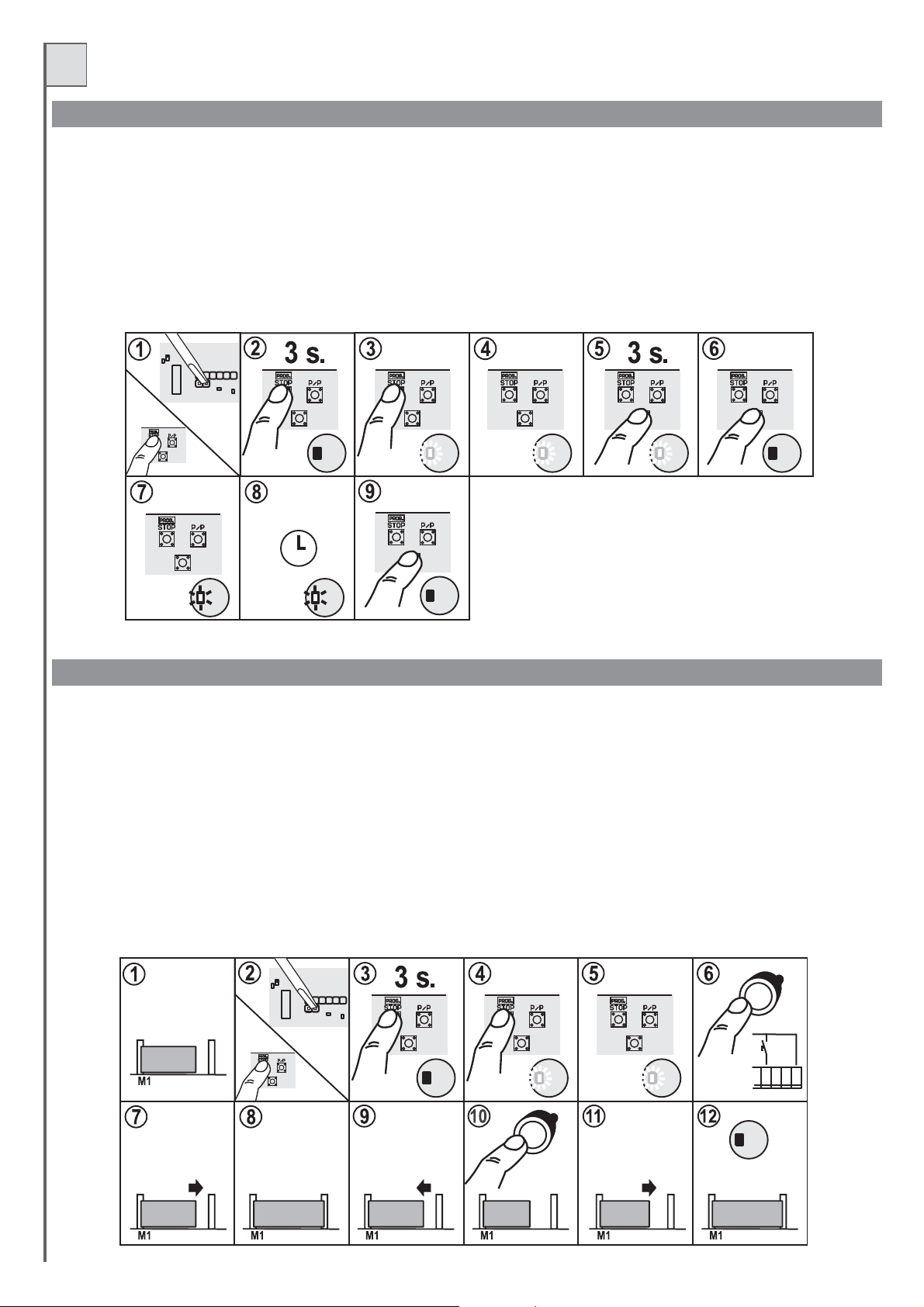
MODIFICATION DU TEMPS DE PAUSE
Le temps depauseest mémorisé durantlaprogrammation des temps.Pourne modifier queceparamètre, procédercommesuit:
1- En maintenantlatoucheProg enfoncée,effectueruneréinitialisation en court-circuitantavecun tournevis lecavalierReset (pos.20fig.1).
2- Maintenir latoucheProgenfoncée.
3-Aubout de troissecondes,la led LD3(etle clignotant)s'allume.Laprocédure deprogrammationest activée.
4- Relâcher latoucheProg.
5-6 Maintenir P3enfoncéejusqu'àl'extinction deLD3.
7- Relâcher P3,laledLD3 clignoteetcommande le réglagedutemps de pause.
8-Attendrele temps désiré
9- Presser latoucheP3pour bloqueretmémoriser le tempsdepause.
La led LD3s'éteintetla logiquedecommande sort delaprogrammation.
Reset
P3
P3 P3 P3
LD3 LD3 LD3
P3
LD3
P3
LD3
Temps
PAUSE
P3
LD3 LD3
P3
LD3
MODIFICATION DE L'OUVERTURE PIÉTON(modalité1 moteur)
- La programmation du temps d'ouverture piéton nefonctionne que sila logique decommande est enmodalité 1 moteur(dip-switch 11 sur
OFF voir part.19fig.1).
Procédure :
1- Bloquer leportaillégèrementouvert
2- En maintenantlatoucheProg enfoncée,effectueruneréinitialisation en court-circuitantavecun tournevis lecavalierReset (pos.20fig.1).
3- Maintenir latoucheProgenfoncée.
4-5-Aubout de troissecondes,la led Ld3(etle clignotant)s'allume.La procédure deprogrammationest activée.
6- À cepoint(contrairementà laprogrammationnormale) nous devonsappuyersur la touchePED(piéton) connectéeau bornier.
7- Le portailpartenfermeture ettrouvela butée defermetureou le findecourse.
8-9- Quand ilestferméil partautomatiquementen ouverture
10- Quand leportailatteintle pointd'ouverture(piéton) désiré presserdenouveau la touchePed(piéton).
11- Le portails'arrêteet se ferme.
12- La ledLD3s'éteintet lalogiquede commande sortdela programmation.
22
Piéton
Reset
P3
P3 P3 P3
LD3 LD3 LD3
Piéton
Piéton
J1
Piéton
19 20 21 22 23
LD3
P/P
COM.
STOP
Fin
Page 23
F
TAB.2
23
Page 24

F
PHOTO-TEST
Pour que lephoto-test fonctionne, l'installation doitprévoir deux lignes d'alimentation pour les photocellules, la première reliée aux bornes 1 e
alimente les récepteurs)ladeuxième aux bornes3et 4 quialimenteles émetteurs (lephoto-testdoit êtreactivéavecle dip-switchn.7 sur ON).
La logique decommandecontrôlel'efficacité des photocellulesensimulant leur interventionàchaque début demanœuvre.
Si tout est OK les moteurs partent et la manœuvre commence, si le récepteur a quelque problème, le cycle s'arrête et est signalé par une série de
clignotements rapides duvoyantportail ouvert etdeLD3.
La fonction photo-test,endehorsde l'aspectsécurité,apporte les avantagessuivants:
- économie d'énergie(lesémetteurs des photocellulesàportail fermé sontéteints)
- augmentation del'autonomieencas d'alimentationàbatteries
- moins d'usuredescomposants de l'émetteurphotocellules.
- Le photo-testfonctionneaussiavec laphotocellule3 (entrée Jolly).
- La logique de commande reconnaît et mémorise (durant la programmation des temps) combien et quelles photocellules ont été
connectées pour lephoto-test.
- Dans des installations avec le photo-test, quand le portail est fermé,les émetteurs desphotocellules ne sontpas alimentés etles entrées
sont ouvertes (ledséteintes).
- Pour letestdesphotocellules avecportailfermé court-circuiter lesdeuxbornes « Test »(pos.11 fig. 1) présentessurla logique.
- Les photocellulesavecconnexionspour photo-testnefonctionnent que durantlamanœuvre.
t 2 (qui
SOFT START
Il est possible de modifier la phase de démarrage des moteurs pour la rendre plus rapide.
Pour modifier le démarrage :
Avec la logique de commande sous tension et le portail fermé presser simultanément les touches STOP/PROG et P3 (pos. 13 et 14 - fig. 1).
Au bout de quelques secondes, la led L3 s'allume (pos. 16 - fig. 1).
Si L3 reste allumée avec lumière fixe, le démarrage sera plus rapide.
Si L3 clignote le démarrage sera plus progressif.
Relâcher les touches pour mémoriser la configuration.
Sur la T224, la configuration d'usine est avec démarrage progressif.
RÉCEPTEUREMBROCHABLEmodèleOC (option)
Les récepteurs sontàauto-apprentissageet peuventmémoriserplus de codesdansle même canal.
Le fonctions desdeuxcanauxradio sont:
Canal 1 Pasàpas
Canal 2 Piéton
Pour mémoriser lesémetteurs,procédercomme suit:
- Monter lerécepteurdansle connecteur(pos.23 fig.1)
-Alimenterla logique decommandeet attendre quelesleds surlerécepteur s'éteignent.
- Sur lerécepteur, presser brièvementlatouche du canalàmémoriser, (P1pasà pas P2piéton)la ledcorrespondantecommenceà clignoter.
Si la ledeffectuedesclignotements doubles attendreetrépéter l'opération (lapetitetouche ne doitêtrepressée qu'uneseulefois).
- Transmettre avec la télécommande à programmer.
- Si la led sur le récepteur effectue un clignotement plus long, cela veut dire que la mémorisation a été correctement effectuée.
- Si le code est déjà présent dans la mémoire, les leds du récepteur clignotent en même temps.
On peut réinitialiser la mémoire des codes en tenant enfoncée la touche P1 du récepteur pendant environ 15 secondes jusqu'à ce que les deux
leds s'allument.
L'antenne doit être connectée aux bornes 42 (conducteur extérieur) et 43 (âme) voir fig. 2.
- Pour de plus amples renseignements et détails, voir le manuel qui accompagne le récepteur.
P1
Led1
Led2
P2
P1
Led1
Led2
24
MEMORIA
P2
Page 25

F
ESSAI FINAL
Effectuer toujours un essai final après avoir fait toutes les programmations nécessaires.
- Contrôler le fonctionnement correct des dispositifs de protection (système anti-écrasement, touche stop, photocellules, barres palpeuses, etc.)
- Contrôler le fonctionnement correct des dispositifs de signalisation (clignotants, voyant portail ouvert, etc.).
- Contrôler le fonctionnement correct des dispositifs de commande (touche P/P, Radiocommandes, etc.).
- Avec le ralentissement activé et après une réinitialisation (ou une coupure de courant) la logique de commande effectue une ouverture
à basse vitesse pour chercher les références (butées).
RECOMMANDATIONS FINALES
L'installation de l'automation doit être effectuée dans les règles de l'art par du personnel spécialisé, conformément aux dispositions légales, à la
directive machine 98/37/CEetauxnormes EN12453et EN 12445.
- S'assurer que les structures existantes (colonnes, charnières, vantaux) soient suffisamment solides pour résister aux forces développées par le
moteur.
- S'assurer quelesarrêts mécaniques enfind'ouverture et enfinde fermeturedesvantauxsoient suffisamment robustes.
- Vérifier l'étatdescâbles qui setrouventéventuellement déjàdansl'installation
- Faire uneanalysedes risques del'automationet adopter,enfonction decelle-ci,les dispositifs desécuritéet de signalisationnécessaires.
- Installer lescommandes(par exemple lesélecteurà clé)demanière à cequel'utilisateurne setrouvepas dans unezonedangereuse.
- Une foisl'installationterminée, tester plusieursfoisles dispositifsdesécurité, de signalisationetde déverrouillage del'automation.
- Appliquer sur l'automation l'étiquette oula plaqueCE où sont indiqués les dangers présentés par l'automationainsi queles données d'identification
de la machine.
- Remettre àl'utilisateurfinal le moded'emploi,les avertissementsconcernantla sécurité etladéclaration CE deconformité.
- S'assurer quel'utilisateura biencompris lefonctionnementautomatique, manuel etd'urgencede l'automation.
Informer par écrit l'utilisateur (par exemple dans le mode d'emploi) de l'éventuelle présence de risques résiduels non couverts et des utilisations
impropres prévisibles.
- Informer l'utilisateurparécrit (par exempledansle moded'emploi):
de la présenceéventuellederisques résiduelsnonprotégés et del'usageimpropre prévisible.
*
De lanécessité decouper l'alimentationquand lenettoyage dela zonede l'automatismea lieuou encas depetites interventionsde maintenance
*
(ex. Repeindre).
De la nécessitédecontrôlerfréquemment l'absencededommages visibles àl'automatismeet s'il yena, avertirimmédiatementl'installateur.
*
Qu'il ne fautpaslaisser les enfantsjouerà proximité del'automatisme.
*
- Etablir unplan de maintenancede l'installation (aumoins tousles6 moispour les dispositifsde sécurité) eninscrivant sur unregistre prévu àcet effet
les interventions effectuées.
ELIMINATION
Ce produit est constitué dedivers composants qui pourraient à leur tour contenirdes substances polluantes. Ne paslaisser ce
produit gagner l'environnement.
DÉCLARATION DE CONFORMITÉ CE
Le soussigné , Représentant légal de l'entreprise :
TELCOMA S.r.l. Via Luigi Manzoni 11, 31015 Conegliano (TV) ITALIE
Déclare que le produit:
Modèle
est conforme aux exigences essentielles de l'article 3 et aux mesures correspondantes de la Directive 1999/5/CE s'il est utilisé conformément
aux usages pour lesquels il a été conçu.
est conforme aux exigences essentielles de la Directive 89/336 (EMC) normes EN 61000-6-3, EN 61000-6-1 et modifications successives s'il est
utilisé conformément aux usages pour lesquels il a été conçu.
est conforme aux exigences essentielles de la Directive 73/23 (LVD) normes EN 60335-1 et modifications successives s'il est utilisé
conformément aux usages pour lesquels il a été conçu.
Lieu et date: Conegliano,
Augusto Silvio Brunello
T224
18/09/2006
Représentant légal
Augusto Silvio Brunello
24
Page 26

E
INSTRUCCIONESPARALAINSTALACIÓN Y LAPROGRAMACIÓN
Estemanual estádestinadoal personaltécnico cualificadoparalas instalaciones
Antes de realizarlainstalación seaconsejaleer detenidamenteestasinstrucciones.
Un uso inadecuadodel productoo un errorde conexiónpodríanperjudicar elfuncionamiento correctodelproducto yser peligrosopara el
usuario final.
CARACTERÍSTICAS
Esta central puedeautomatizar:
- cancelas dedoshojas conosin findecarrera
- cancelas deunahoja cono sinfinde carrera
- cancelas correderasdoblescon findecarrera
- cancelas correderassimplescon findecarrera
La central estáequipadacon:
- control delmotorpor encodery/o amperimétrico
- desaceleración delmotorprogramable
- arranque suave(softstart)
- control delfuncionamientode lasfotocélulas(Fototest)
- autodiagnóstico delcontrolde losmotores(MOSFET)
- conectores parareceptoresOC y/oreceptores TARJETA
DATOSTÉCNICOS
Parámetroseléctricos U.M. T224
Alimentación Vac 230±10%
Frecuencia Hz 50/60
Absorción en standby(230V) mA 18 / 25 mín /máx
Absorción máxima (230V) A 2
Potencia máx. motores24V VA 360(2X180)
Temperatura de funcionamiento °C -20 +60
Medidas de lacaja(L x HxP) mm 220x280x120
26
Page 27

E
12
13
14
15
16
17
18
11
10
9
8
7
1
2
3
4
5
ON
6
7
8
9
10
ON
11
ON
M1
M2
12
19
20
21
22
23
24
6
5
4
6
27
26
25
2
3
FUSE 5X20
Fig.1
1
DESCRIPCIÓNDE LASPIEZAS(Fig. 1)
1 Fusible delínea230V T2A(5x20retardado)
2 Regleta deconexiónpara lalínea dealimentación230V
3Transformador
4 Regleta deconexiónpara secundario,transformador ycargadorde baterías(opcional)
5 Regleta deconexiónpara luzde cortesía(contacto)
6 Fusible debajatensión 24VF16A(5x20)
7 Fusible debatería/cargadorde baterías24V T10A (5x20retardado)
8-22Trimmerde regulación potenciamotores
9-21 Led defuncionamientomotores (LD1yLD2)
10 Fusible auxiliares24VF5A(5x20)
11Test fotocélulas(véase elcapítulo FOTOTEST)
12 Regleta deconexiónpara: alimentaciónauxiliares, indicadorluminosocancela abiertayelectrocerradura.
13 Botón deProgramacióny Parada*.
14 Botón P3(programacióntiempo dePausa)
15 Botón Pasoapaso (P/P)
16 Led Programación(LD3)
17 Regleta deconexiónpara mandosy dispositivosdeseguridad
18 Led deseñalizaciónestado entradasdemando. Ledencendido= entradacerrada; ledapagado =entrada abierta
19 Dip-switch funciones
20Reajuste de lacentral(cortocircuitar por uninstantelos 2 contactosequivalea cortar yactivarnuevamente la alimentacióndela central)
23 Conector paraconectarun receptorcon tarjetamodeloOC (opcional)
24 Conector paraconectarun receptorcon tarjeta(opcional)
25 Regleta deconexiónpara antenay segundocanaldel radiorreceptor
26-27 Regletas deconexiónpara losmotores
*Este botón dePARADA (STOP) sinosólo de servicioparafacilitar los testdurantela instalación.
27
nodebe ser consideradodeseguridad
Page 28

E
INSTALACIÓN
El equipodebe ser instaladoCORRECTAMENTE por personal que posealos requisitos establecidospor las leyesvigentes y siguiendo
las normativas EN12453y EN12445 sobrelaseguridad dela automatización.
- Controle quelaautomatización estéequipadacon topesyque estostengan lasdimensiones adecuadasparael pesode lacancela.
- Fije lacentralsobre unasuperficieen planoyfirme, protegidaadecuadamente contragolpes einundaciones.
CARGADORDEBATERÍAS CB24 (opcional)
Una instalación con T224 puede funcionar también sin tensión de línea, porque se pueden instalar dos baterías recargables de 12V
2,2Ah (no incluidasenel suministro)yun cargadordebaterías mod.CB24, todoesto sintener quemodificarel restode lainstalación.
En instalacionesnuevas seaconseja conectarlas bateríasy elcargador debaterías después del ensayo final, seguir lasindicaciones de
la figura 2yobservar muybienla polaridaddelos conductores.
Secuencia de conexión:
- corte laalimentaciónde 230V.
- conecte losbornes3 y4 delCB24a losbornes 28y 29dela centralT224.
- conecte las2baterías (enserie), conloscables suministrados,alos bornes1 y2del cargadorde baterías.
- controle quelacentral estéalimentada correctamente.
- active nuevamentelaalimentación de230V.
- Las bateríasnuevasse cargaráncompletamente despuésde10 horas.
- La cantidaddemaniobras quese puedenrealizarcon laalimentación delas bateríasdependede muchosfactores;
un ejemplo indicativopuedeser 4ciclos completosenlas siguientescondiciones:
- cancela de150kg porcada hoja
- instalación con2pares defotocélulas, receptorenchufabley 1luz intermitente(20Wmáx.)
- baterías cargadas
- antes de5horas apartir delcortede laalimentación de230V
- Lacentral disminuyeel destello de la salida de la luzintermitente enla siguiente condición: funcionamiento con batería sinla
línea de 230V.
CONEXIONESELÉCTRICAS
Para las conexiones,sigala tabla1y lafigura2.
En el caso de instalaciones ya montadas, es oportuno realizar un control general de las condiciones de los conductores (sección,
aislamiento, contactos) ydelos equiposauxiliares(fotocélulas, receptores,botoneras,selectores dellave, etc.).
Acontinuación,damos algunosconsejospara unainstalacióneléctrica correcta:
- los tubos que entran en la caja estanca de la central deben instalarse manteniendo invariado, dentro de lo posible, el grado de
protección IP56 original.
- La seccióndelos cablesdebe calcularsesegúnsu longitudyla corrientemáxima.
- No utiliceuncable multipolarúnico paratodaslas conexiones(línea,motores, mandos,etc.) oencomún conlos demásequipos.
- Divida lainstalaciónen dospartescomo mínimo,porej.:
1) parte de potencia (línea de alimentación, motores, luz intermitente, luz de cortesía, electrocerradura); sección mínima de los
conductores 1,5 mm2(líneade losmotores2,5 mm2).
2) parte deseñal(mandos, contactosde seguridad,alimentaciónde losauxiliares);sección mínimade losconductores0,75 mm2
- Cuando los cables de mando tengan tramos muy largos (más de 50 metros) se aconseja desacoplarlos con relés montados cerca de la
central.
- Todas lasentradas N.C.(normalmentecerradas) queno seutilicen enla centraldebencortocircuitarse conel común.
- Todos loscontactos N.C.asociadosa unamisma entradadeben conectarseen serie.
- Todos loscontactos N.A.(normalmenteabiertos) asociadosa unamisma entradadeben conectarseenparalelo.
- Para la alimentación de la central está previsto el MONTAJE DE UN SECCIONADOR exterior (no incluido en el suministro)
independientey dimensionadosegúnla carga.
28
Page 29

E
24Vcc
Indicador luminoso
cancela
abierta
24Vcc
Alimentación
fotocélulas
con Fototest
(véase texto)
24Vcc
Rx Tx
Aux.
24Vcc
11121231341451561671781891910
24Vcc
Luz
intermitente
Electrocerradura
12Vcc
COM.
BANDA ABRIR
C.AP
PHOTOCELL. 2
FT2
PHOTOCELL. 1
FT1
JOLLY 4
J4
JOLLY 3
J3
COM.
JOLLY 2
J2
JOLLY 1
J1
PEATONES
PED.
STOP
STOP
P/P
P/P
COM.
24V
230V
24
24
25
25
24V
max. 50W
230V
max. 100W
26 27 28 29
30 3531 3632 3733 3834 39
DD
M1 M2
ENC 1 ENC 2
1234
12V 2,2Ah
20 21 22
40 41 42 43
2°Ch. antena
23
29
Fig.2
FUSE 5X20
44
45
230V
50/60 Hz
12V 2,2Ah
Page 30

E
Tab.1
Born n. Borne n.
12
34
56
7
8
910
11
17
23
23
23
23
25
25
, 17, 23
, 17, 23
, 11, 23
, 11, 23
, 11, 23
, 17, 11
, 17, 11
, 17, 11
, 17, 11
, 17, 11
12 11
13
14
15 17
16 17
18 23
19
20
21
22
24
24
26 27
2928
30
32
35
37
40
31
33e34
36
38e39
41
42
43
44
45
Dispositivo
Auxiliares
Tx fotocélulas
Indicador
luminoso
Luz intermitente
o bombilla
Electrocerradura
Contacto n.c.
Contacto n.c.
Contacto n.c.
Contacto
Contacto
Contacto
Contacto
Botón n.a.
Contacto n.c.
Botón n.a.
Lámpara
Lámpara
Transformador
Cb24
Motor M1
Encoder M1
Motor M2
Encoder M2
Auxiliar
Antena Rx*
Antena Rx*
Línea
V Imáx
24Vdc
1A
24Vdc 1A
24Vdc1A1A
24Vdc
12Vdc
1A
24V
2A
230Vac
0,5A
22Vac
6,8A
24Vdc
10A
24Vdc
5A
24Vdc
5A
Máx 24V 500mA
230Vac
2A
Función
Alimentación
Alimentación Tx para fototest.
Cancela abierta
Indicador de movimiento
Durante las maniobras con la central alimentada sólo con
baterías, disminuye la frecuencia de destello
Bloqueo mecánico
Banda sensible en abrir
Fotocélula 2
Fotocélula 1
Jolly 4
Jolly 3
Jolly 2
Jolly 1
Paso de peatones
Parada
Paso a paso
Luz de cortesía
Luz de cortesía
Alimentación
Cargador de baterías (opcional)
Abrir/cerrar
Sensor de movimiento
Abrir/cerrar
Sensor de movimiento
Segundo canal recepto
Trenza
Central
Alimentación central
Notas
Permanente parala alimentaciónde las fotocélulasy receptoresexteriores.
Si la instalación prevé el funcionamiento con Fototest conecte aesta salida
sólo losreceptores (RX)de las fotocélulas
Alimentaciónpara TX fotocélula(con funciónFototest activa)
Activadesde el comienzode lamaniobra conla cancela cerradacompletamente.
Destellos diferentes según el estado de la cancela:
cancela cerrada = apagado en apertura = destello lento
en cierre = destello rápido en pausa = 2 destellos con pausa
cancela bloqueada con botón parada = luz encendida fija
después de un reajuste o corte de corriente el indicador luminoso está apagado.
Destello durante la maniobra. El encendido puede anticiparse (destello
previo), véasedip switchfunciones n° 5.
La salida es laluz intermitente es decir que se puede conectaruna bombilla
de 24Vnormal..
Activa, durante algunos segundos, en cada inicio de apertura.
Durante la apertura detiene el motor y cierra durante algunos segundos.
Conecte esta entrada al común si no se la utiliza.
Durante la apertura, bloqueo momentáneo, durante el cierre, invierte la marcha.
Conecte esta entrada al común si no se la utiliza.
Durante el cierre invierte la marcha.
Conecte esta entrada al común si no se la utiliza.
Véase “modo entradas Jolly” tab.2 (dip-switch n° 3 y 4).
Véase “modo entradas Jolly” tab.2 (dip-switch n° 3 y 4).
Véase “modo entradas Jolly” tab.2 (dip-switch n° 3 y 4).
Véase “modo entradas Jolly” tab.2 (dip-switch n° 3 y 4).
Véase “modo entradas Paso a Paso y Paso de peatones” tab.2 (dip-switch
n° 1 y 2).
Bloqueo de todas las funciones.
Conecte esta entrada al común si no se la utiliza.
Véase dip-switch funciones n° 1 y 2
Encendida al comienzo de la maniobra 3 minutos después del cierre completo.
Contacto a conectar como indicado en los esquemas de fig.2
Encendida al comienzo de la maniobra 3 minutos después del cierre completo.
Contacto a conectar como indicado en los esquemas de fig. 2.
Conecte esta entrada al secundario del transformador suministrado (22V).
Predisposición para la conexión del cargador de baterías CB24 (opcional)
y de las baterías (opcional)
El motor M1 retarda en el cierre.
En instalaciones batientes, el motor M1 acciona la hoja con la electrocerradura.
Sistema disponible en algunas versiones de motor.
Respete la polaridad del borne 32(-), borne 33(+) y borne 34(D).
El motor M2 retarda en la apertura.
Sistema disponible en algunas versiones de motor.
Respete la polaridad del borne 37(-), borne 38(+) y borne 39(D).
Disponible sólo si se inserta una tarjeta radio bicanal en el conector
respectivo (detalle 24 de fig.1)
Si se conecta un receptor al conector respectivo, véanse las
características de la antena requeridas por el fabricante.
Conecte a la línea de 230Vac. Véase conexiones eléctricas.
Salida
Entrada
*ANTENA: si se utiliza una tarjeta radio enchufable (tipo SR), tenga cuidado porque en algunos modelos el conector para la conexión de la antena está
en la misma tarjeta.
30
Page 31

E
MANIOBRADE POSICIONAMIENTODELOSMOTORES
Con este procedimientose puedenmaniobrar aplacer los motoresconectados ala central afin depreparar lainstalación para laprogramación ypara
saber si losmotoresestán conectados correctamente.
Duranteesta operaciónlosbotonesfuncionan enmodo“hombre presente” ylosdispositivos de seguridadestáninhibidos.
Procedimiento:
1- Haga unreajustedela central(cortocircuitandoel jump Resetdet.20 de Fig.1).
2- Pulse elbotónP3(det. 14defig.1) durante unos3segundos.
3- Cuando elledLD3(y laluzintermitente) se enciende,suelteel botón P3.Procedimientoactivado.
4- Pulse elbotónPROGpara abrirM1(si el motorcierra,invierta los hilos30con 31).
5- Pulse elbotónP/Ppara abrirM2 (siel motor cierra,inviertalos hilos 35con36).
6- Pulsando elbotónP3simultáneamente conelbotón PROG, elmotorM1 cierra.
7- Pulsando elbotónP3simultáneamente conelbotón P/P, elmotorM2 cierra.
8- Si laoperación siguiente es una programación, coloque las hojas (o la hoja)en la posición de cancela casi abierta: las hojas deben tener espacio
suficiente como paramoverseen cierre duranteunos5 segundos.
9- Para volveralfuncionamientonormal, realiceunreajuste de lacentral(cortocircuite el conectordet.20 defig.1).
P3 P3 P3
P3 P3
Reset
P3
LD3 LD3
Reset
NOTAS SOBRE LAPROGRAMACIÓNDELOS TIEMPOSDE FUNCIONAMIENTOY PAUSA
Esteprocedimiento esobligatorioen lasinstalacionesnuevas; lafinalidadesla dehacerque lacentralmemoricelos tiemposdemaniobra yalgunosparámetros
útilesparaladetección delos obstáculos.
Haydisponiblesdostipos deprogramación detiempos:
-1)programaciónautomática delos tiempos(simplificada),
-2)programaciónavanzada (manual)de lostiempos.
La eleccióndebe hacerse segúnel tipode automatización;laprimera (automática)tieneparámetros comolostiempos deretardode lahoja(desincronización)y
eltiempodedesaceleración; conla segunda(manual)sepuedenmemorizarconprecisiónla zonade desincronizacióndelahojayaquelladedesaceleración.
- Si tuvieradudas, se aconsejacomenzar con la programaciónautomática y despuéspasar a lamanual únicamente si lashojas se chocanentre sí
duranteelfuncionamiento.
- La programación manual es obligatoria en las instalaciones asimétricas, donde la hoja que debe cerrar primero tiene un ángulo de maniobra
superioraldela otrahoja.
Durantela etapadeaprendizaje seaccionarávariasveces elbotónP/P (det.15defig. 1);comoalternativa sepuedeutilizarel mandoP/P(borne22, fig.2)obien
eltransmisormemorizadoen elprimer canaldelreceptor.
Notasimportantesatener encuenta antesdelaprogramación:
-Enlasinstalaciones conelectrocerradura éstadebemontarseenlahojaconectadaal motorM1.
-Alimentelacentral ycontrole,mediantelosLeds correspondientes,quelasentradas demando funcionencorrectamente(los contactosN.C.debentenerelLed
encendido,loscontactosN.A. debentener elLedapagado).
- Silos transmisoresdelas fotocélulasestán alimentadoscon lasalidapara elfototest (bornes3 y4) controlesufuncionamiento cortocircuitandoel JumperTest
(det.11defig.1).
-Desconectelasbaterías siestuvieran montadas.
-Coloquelostrimmers dela sensibilidadenelcentroparaobtenerunasensibilidadmedia delobstáculo.
-Dejelibrela zonade movimientodelacancela.
-Ejecuteelautoaprendizaje delos tiemposseleccionandounadelasprogramacionesdescritasa continuación.
- Coloque las hojas (o la hoja) en la posición de cancela casi abierta: las hojas deben tener espacio suficiente como para moverse en cierre durante unos 5
segundos.Silashojas noestán enposición,sepuederealizarelprocedimientodescrito enel párrafoanterior.
-Siseestá utilizandoun solomotor,coloqueeldip 11en OFFy conécteloalosbornesdelmotorM1.
- Si se trata de una instalación de dos hojas (correderas o batientes), coloque el dip 11 en la posición ON. El motor conectado a los bornes de M1 arrancará
primero en apertura y tendrá la electrocerradura montada, mientras que el motor M2 arrancará primero en cierre (obviamente durante el funcionamiento
normal,elprocedimientode aprendizajetiene unordendemovimientomuydiferentealdel funcionamientoordinario).
31
Page 32

E
PROGRAMACIÓNAUTOMÁTICA(simplificada)
Procedimiento:
1 -Coloquelas hojas(ola hoja)enla posicióndecancela casiabierta: lashojasdeben tenerespaciosuficiente comoparamoverse encierre duranteunoscinco
segundos.Silashojas noestán enposición,sepuederealizarelprocedimientodescrito enel párrafoanterior.
2-Manteniendopulsadoel botónPROG, realiceunreajustecortocircuitandoeljumpResetcon eldestornillador (det.20deFig.1).
3-Mantengapulsadoel botónPROG.
4-Despuésdetres segundos,el ledLD3(ylaluzintermitente)seencenderá. Elprocedimiento deprogramaciónseactiva.
5-Pulseelbotón P/Ppara iniciarel autoaprendizaje.LahojaM2arrancaencierre duranteunos 3-5seg.ydespuéssedetiene
6-LahojaM1 realizael mismomovimientoinmediatamentedespués.
IMPORTANTE: en este movimiento las hojas no deben llegar hasta el tope; si esto sucede, repita el autoaprendizaje (colocando las hojas en una
posiciónquelogrencerrarse durante5 segundossinquelleguenhastaeltope).
7-LahojaM1 arrancaen aperturadurante3-5seg.ysedetiene.
8-Inmediatamentedespués,la hoja2 realizaelmismomovimiento(3-5seg.seabrey despuésse detiene).
MPORTANTE:también duranteestemovimientolas hojasnodeben llegarhasta eltope; siestosucede,colóquelas enunaposiciónmejor yrepitael
I
autoaprendizaje. Entonces,la centraldetectarátodos losparámetros delas doshojas(presencia-ausencia encodery suvelocidad, corrienteenlos
motores).
- Duranteesta maniobrala centraldetectará lapresencia delos encodersen los motores:NO ESTÁADMITIDOtener unmotor conencoder yel otro
motorsin encoder;si asífuera(por ejemploporunaaveríaenel encoderdeunode losmotores) lacentralemitirá unaseñal deerrorformada dediez
destellosdelledLD3 ydel indicadorluminoso.
-La deteccióncorrecta delapresencia delos encoderspuedecontrolarse observandolosledsdefuncionamientode losmotores(dets.9y21deFig.
1);sielled relativoal motorenmovimientodestella,entonceselencoderrespectivo hasido detectado.
Sielledqueda encendidocon luzfija,entonceselencodernohasido detectado.
- Si la central no detectara el encoder en ambos motores, la detección del obstáculo se efectuará monitoreando la corriente durante el
funcionamiento.
9-Lahojacon M2se cierracompletamente.
10-Tambiénse cierraM1.
11-12-Cuandoambashojas estáncerradas, M1arrancaautomáticamenteenapertura.
13-CuandoM1está abierto,M2 tambiénseabrecompletamente.
14-Cuandolasdos hojasestán enposicióndeapertura,comienzalamemorizacióndel tiempode pausa.
15-Transcurridoel tiempodepausadeseado,pulseelbotónP/P,elmotor M2arrancará encierre.
16-CuandoM2llega altope, M1secierra.
17-Cancelacerradacompletamente.
18-Findela programación(la centralsepreparaautomáticamenteparaelfuncionamientonormal).
-Losvaloresmemorizados quedanalmacenados hastalapróximamemorización.
- Este procedimiento simplificado de programación configura automáticamente los valores de los retardos de la hoja y de los puntos de
desaceleración,utilizandovalorespor defecto.
- Si dichas configuraciones fueran inadecuadas para la instalación, habrá que proceder con la programación avanzada descrita en el siguiente
párrafo.
32
P3
Reset
P3
P3 P3
LD3 LD3
P3
LD3
Page 33

E
PROGRAMACIÓN AVANZADA (manual)
Estetipo deprogramaciónpermiteconfigurar manualmentelosretardos de lahojay los puntosdedesaceleración.
Procedimiento:
Siga los puntosdesde1a 10delpárrafo anterior “Programaciónautomática”.
Proceda conlas siguientes instrucciones,teniendo en cuenta que, contrariamente a la programaciónautomática, en esta se debedar una secuencia
de referencia entiemporeal.
11-12- Cuando ambashojasestán cerradas, M1arrancaautomáticamente en apertura.
13- Pulse el botón P/Pcuando lashojas llegana ladesincronización (deapertura) deseada.Para evidenciar y confirmar la memorización, el motor M1
se detiene duranteuninstantey arrancaenapertura.
14- Pulse elbotónP/Pcuando lahojaconM1 llegaala zona (deseada)dedesaceleración. Para evidenciaryconfirmar la memorización,elmotor M1se
detiene durante uninstanteyarranca enapertura.
15-16- Cuando M1llegaaltope (ofinde carrera) deapertura,M2 arranca automáticamenteenapertura.
17- Pulse elbotónP/Pcuando lahojaconM2 llegaala zona (deseada)dedesaceleración. Para evidenciaryconfirmar la memorización,elmotor M2se
detiene durante uninstanteyarranca enapertura.
18- Cuando lasdoshojasestán enposiciónde apertura, comienzalamemorización del tiempodepausa.
19-Transcurridoeltiempo de pausadeseado,pulse elbotónP/P,el motor M2arrancaráen cierre.
20- Pulse el botón P/Pcuando lashojas llegana ladesincronización (decierre) deseada. Para evidenciar yconfirmar lamemorización, elmotor M2se
detiene durante uninstanteyarranca encierre.
21- Pulse elbotónP/Pcuando lahojaconM2 llegaala zona (deseada)dedesaceleración. Para evidenciaryconfirmar la memorización,elmotor M2se
detiene durante uninstanteyarranca encierre.
22- Cuando M2llegaaltope, M1secierra.
23- Pulse elbotónP/Pcuando lahojaconM1 llegaala zona (deseada)dedesaceleración. Para evidenciaryconfirmar la memorización,elmotor M1se
detiene durante uninstanteyarranca encierre.
24- Cancela cerradacompletamente.
25- Fin delaprogramación(la centralseprepara automáticamente paraelfuncionamiento normal).
- Los valoresmemorizadosquedanalmacenados hastalapróxima memorización.
P3 P3 P3
Tiempo
PAUSA
23 24 25
P3 P3
P3
LD3
P3
33
Page 34

E
MODIFICACIÓNDELTIEMPODEPAUSA
Eltiempo depausasememoriza durantelaprogramación de lostiempos.Para modificar sóloesteparámetro, procedade lasiguiente manera:
1- Manteniendo pulsadoelbotónPROG, realiceunreajuste cortocircuitando eljumpReset con eldestornillador(det. 20de fig.1).
2- Mantenga pulsadoelbotónPROG.
3- Después detressegundos,el ledLD3(y la luzintermitente)se encenderá. Elprocedimientode programaciónse activa.
4- Suelte elbotónPROG.
5-6 Mantenga pulsadoP3hastaque LD3seapague.
7- Suelte P3,elledLD3 parpadeaycomienza la memorizacióndeltiempo de pausa.
8- Espere eltiempodepausa deseado.
9- Pulse elbotónP3para bloquearymemorizar el tiempodepausa.
El led LD3seapagay lacentralsale de laprogramación.
3 seg.3 seg.
Reset
P3
P3 P3 P3
LD3 LD3 LD3
P3
LD3
P3
LD3
Tiempo
PAUSA
P3
LD3 LD3
P3
LD3
MODIFICACIÓNDELAAPERTURAPARAPASODEPEATONES(modalidad1 motor)
- La programación deltiempo parapaso depeatones funcionasólo sila centralestá enmodalidad 1motor (dip-switch11 en OFF, véase det.
19 de fig.1).
Procedimiento:
1- Bloquee lacancelaligeramenteabierta.
2- Manteniendo pulsadoelbotónPROG, realiceunreajuste cortocircuitando eljumpReset con eldestornillador(det. 20de fig.1).
3- Mantenga pulsadoelbotónPROG.
4-5- Después detressegundos,el ledLd3(y la luzintermitente)se encenderá. Elprocedimientode programaciónseactiva.
6- Entonces (contrariamentealaprogramación normal)pulseel botón PED(peatones)conectado en laregletade conexiones.
7- La cancelaarrancaencierre yencuentrael tope oelfin de carreradecierre.
8-9- Cuando estácerrada,arrancaautomáticamente enapertura.
10- Cuando lacancelallegaal puntodeapertura deseado (pasodepeatones), pulse nuevamenteelbotón PED (peatones).
11- La cancelasedetiene y despuéssecierra.
12- El ledLD3seapaga ylacentral sale delaprogramación.
34
3 seg.
Peat.
Reset
P3
P3 P3 P3
LD3 LD3 LD3
Peat.
Peat.
J1
PEAT.
19 20 21 22 23
LD3
P/P
COM.
STOP
Page 35

E
TAB.2
35
Page 36

E
FOTOTEST
Para que el fototest funcione, la instalación debe tener dos líneas de alimentación para las fotocélulas; la primera conectadaa los bornes 1 y 2 (que
alimenta alos receptores),la segundaa losbornes 3y 4que alimentana lostransmisores (elfototest debeestar habilitadocon eldip-switch n°7 enla
posición ON).
La central controlalaeficiencia de lasfotocélulassimulando una activaciónencada inicio delamaniobra.
Si todo es correcto, los motores arrancan y comienza la maniobra; si el receptor tiene algún problema, el ciclo se detiene y se señalan una serie de
destellos veloces delindicadorluminoso cancela abiertaydel led LD3.
La función fototest,ademásdelfactor seguridad,tienelas siguientes ventajas:
- ahorro deenergía(lostransmisores delasfotocélulas con lacancelacerrada están apagados)
- aumento delaautonomíaen elcasode alimentación conbaterías
- menor desgastedeloscomponentes deltransmisorde la fotocélula.
- El fototesttambiénfuncionacon lafotocélula3 (entrada Jolly).
- La centralreconoce y memoriza (durantela programación de lostiempos) la cantidad y cuáles son las fotocélulas que están conectadas
parael fototest.
- En las instalaciones con el fototest, cuando la cancela está cerrada, los transmisores de las fotocélulas no están alimentadas y las
entradasestán abiertas(ledsapagados).
- Para elensayodelas fotocélulasconla cancela cerrada,cortocircuitelos dos terminales“Test” (detalle11 defig.1)presentes en lacentral.
- Las fotocélulasconconexionespara elfototestfuncionan únicamente durantelamaniobra.
ARRANQUE SUAVE
Es posible modificar el arranque de los motores para que sea más rápido.
Para modificar el arranque:
Con la centralita alimentada y la cancela cerrada, pulse simultáneamente los botones STOP/PROG y P3 (det. 13 y 14 de fig. 1)
Transcurridos algunos segundos, se encenderá el led L3 (det. 16 de fig. 1).
Si L3 quedara encendido con luz fija, el arranque será más rápido.
Si L3 destellara, el arranque será más gradual.
Suelte los botones para memorizar la configuración.
La configuración de fábrica en la T224 es con arranque gradual.
RECEPTORENCHUFABLE modelo OC (opcional)
Los receptores sondeautoaprendizajey puedenmemorizarvarios códigos enelmismo canal.
Las funciones dedoscanalesradio son:
Canal 1 Pasoapaso
Canal 2 Pasodepeatones
Para memorizar lostransmisores,proceda de lasiguientemanera:
- Conecte elreceptoralconector (detalle23de fig. 1).
-Alimentela central yesperea que losledsdel receptorseapaguen.
- Pulse brevemente en el receptor el botón del canal que se ha de memorizar (P1 paso a paso o P2 paso de peatones), el led correspondiente
comenzará a parpadear.
Si el leddestelladoble,espere yrepitala operación (elbotóndebe pulsarse sólounavez).
-Transmitaconel telemando aprogramar.
- Si elleddelreceptor realizaundestello más prolongado,quieredecir que lamemorizaciónse haconcluidocorrectamente.
- Si elcódigoestámemorizado, losledsdel receptor destellaránsimultáneamente.
Es posible reajustar la memoria de los códigos manteniendo pulsado el botón P1 del receptor durante unos 15 segundos hasta que ambos leds se
enciendan.
La antena debeconectarsealos bornes42(trenza) y 43(central)véase la fig.2.
- Para másinformacionesyespecificaciones, véaseelmanual del receptor.
P1
Led1
Led2
P2
P1
Led1
36
Led2
MEMORIA
P2
Page 37

E
ENSAYOFINAL
Siempre realice unensayofinal después dehaberhecho todas lasprogramaciones.
- Controle que los dispositivos de protección funcionen correctamente (sistema antiaplastamiento, botón de parada, fotocélulas, bandas sensibles,
etc.)
- Controle quelosdispositivos de señalizaciónfuncionencorrectamente (luces intermitentes,indicadoresluminoso cancela abierta,etc.).
- Controle quelosdispositivos de mandofuncionencorrectamente (botón P/P, Radiomandos,etc.).
- Con la desaceleración habilitada y después de un reajuste (o un corte de alimentación), la central ejecuta una apertura a velocidad baja
paraencontrar lospuntosdereferencia (topes).
RECOMENDACIONES
FINALES
- La instalación delautomatismo debeser realizada según los cánones,por personalcualificado que reúna los requisitos establecidos porla leyy de
conformidad con laDirectivasobre máquinas 98/37/CEycon las normasEN12453 y EN12445.
- Compruebe lasolidezde las estructurasexistentes(columnas, bisagras,hojas)en relación conlasfuerzas desarrolladas porelmotor.
- Controle quehayaretenes mecánicos desolidezadecuada enlospuntos de findeaperturay definde cierre delashojas.
- Controle elestadode los cablesyaexistentes enlainstalación, en sucaso.
- Haga unanálisisde los riesgosdelautomatismo yadoptelos dispositivos deseguridadylas señalizacionesnecesariasen consecuencia.
- Instale losmandos(por ejemplo, elselectorde llave)demanera que elusuarionose encuentreenuna zona peligrosa.
- Terminada lainstalación, pruebe variasveceslos dispositivos deseguridad,señalización ydesbloqueo delautomatismo.
- Aplique enelautomatismo una etiquetaouna placa CEquecontenga lasinformacionesdepeligro ylosdatos de identificación.
- Entregue alusuariofinal las instruccionesparael uso,lasadvertencias para laseguridadyla declaraciónCEde conformidad.
- Asegúrese dequeel usuario hayacomprendidoel correcto funcionamientoautomático, manual ydeemergenciadel automatismo.
- Informe alusuario porescrito(por ejemplo,en los manualesde instrucciones)dela eventualpresencia de riesgosresiduales noprotegidosy deluso
inadecuado previsible.
- Informe alusuariopor escrito (porejemploen las instruccionesde uso) :
*
sobre la presenciaderiesgos residuales noprotegidosy sobre elusoinadecuado previsible.
*
que debe desconectarlaalimentación cuando hacelalimpieza en lazonade la automatizaciónosi haceunpequeñomantenimiento (ej.:Pintar).
*
que debe controlar a menudo que la automatización no presente daños visibles y, en el caso de que los haya, deberá advertir de inmediato al
instalador
*
que no debepermitirquelos niñosjueguenen las cercaníasdela automatización
- Predisponga un programa de mantenimientode lainstalación (al menos cada 6 meses para los dispositivosde seguridad),anotando en un registro
expresamente dedicado lasintervencionesrealizadas.
ELIMINACION
Este producto estáconstituido porvarios componentes quepodrían, asu vez, contenersustancias contaminantes.¡No los viertaen el
medio ambiente!
DECLARACIÓN DE CONFORMIDAD CE
El que suscribe , Representante legal de la empresa:
TELCOMAS.r.l., Via LuigiManzoni 11, 31015Conegliano (TV)ITALIA
Declara que elproducto:
Modelo
Es conforme alosrequisitos esenciales delartículo3 y alascorrespondientes disposiciones delaDirectiva 1999/5/CE,siseutiliza para
los usos previstos.
Es conformea los requisitos esenciales de la Directiva89/336 (EMC)y de las normas EN61000-6-3, EN61000-6-1 y sucesivas modificaciones, sise
utiliza para losusosprevistos.
Es conforme a los requisitos esenciales de la Directiva 73/23 (LVD) y de lasnormas EN60335-1 ysucesivas modificaciones,si seutiliza paralos usos
previstos.
Lugar y fecha:Conegliano,
Augusto Silvio Brunello
T224
18/09/2006
Representante legal
Augusto Silvio Brunello
37
Page 38

GB
INSTRUCTIONS FOR INSTALLATION AND PROGRAMMING
- This handbook is aimed at qualified technical installation personnel
- Carefully readallinstructions inthishandbook beforeinstallation.
- Improper useofthe productor incorrectconnectionscould impaircorrectoperation ofthe unitandsafety ofthe finaluser.
FEATURES
This control unit is designed for the automation of:
- two-leaf gates with or without limit switches
- single leaf gates with or without limit switches
- double leaf sliding gates with limit switches
- single leaf sliding gates with limit switches
The control unit is equipped with:
- encoder and/or current sensitivity motor control
- programmable motor deceleration
- soft start
- photocell operation check (Photo Test)
- self-diagnostics of motor drives (MOSFET)
- connectors for OC receivers and/or BOARD receivers
TECHNICAL DATA
Electrical parameters U.M. T224
Power supply Vac 230 ±10%
Frequency Hz 50/60
Absorption on stand-by (230V) mA 18 / 25 min / max
Maximum absorption (230V) A 2
Max. motor output 24V VA 360 (2X180)
operating temperature °C -20 +60
Box dimensions (L x H x D) mm 220x280x120
38
Page 39

GB
12
13
14
15
16
17
18
11
10
9
8
7
1
2
3
4
5
ON
6
7
8
9
10
ON
11
ON
M1
M2
12
19
20
21
22
23
24
6
5
4
6
27
26
25
2
3
FUSE 5X20
Fig.1
PART DESCRIPTION (Fig. 1)
1 Fuse for 230V line T2A (5x20 slow-acting)
2 Terminal board for connection of 230V power line
3 Transformer
4 Terminal board for connection of transformer secondary winding and battery charger (optional)
5 Terminal board for connection of courtesy light (N.O. contact)
6 Low voltage fuse for 24V F16A (5x20)
7 Battery/battery charger fuse 24V T10A (5x20 slow-acting)
8-22 Trimmer for motor power adjustment
9-21 Motor operation leds (LD1 and LD2)
10 Auxiliary fuse 24V F5A(5x20)
11 Photocell Test (see chapter PHOTO-TEST)
12 Terminal board for connection of: auxiliary power supply, gate open indicator and electric lock.
13 Pushbutton for Programming and Stop*.
14 Pushbutton P3 (Pause time programming)
15 Step-by-Step pushbutton (S/S)
16 Programming Led (LD3)
17 Terminal board for connection of controls and safety devices
18 Indicator leds for control input status. Led on = input closed; led off = input open
19 Function Dip-switches
20 Control unit Reset (short the 2 pins briefly to cut off and restore power on the control unit)
23 Connector for insertion of OC model board type receiver (optional)
24 Connector for insertion of board type receiver (optional)
25 Terminal board for connection of aerial and second channel of radio receiver
26-27 Terminal board for connection of motors
1
*This STOPpushbuttonmust neverbe consideredasafety device,but exclusivelya servicefunctionto facilitatetestsduring installation.
39
Page 40

GB
INSTALLATION
The equipmentmust beinstalled "PROFESSIONALLY" bypersonnel withqualifications asenvisaged bycurrent legislationand incompliance withthe
standards EN 12453andEN12445 governingsafetyof the automation.
- Ensure thattheautomationis equippedwithend stops andthatthese are correctlysizedto suit theoverallweight of thegate.
- Fix thecontroluniton aflatand immobile surface,suitablyprotected against theriskof impactandflooding.
BATTERY CHARGER CB24 (optional)
A system with the T224 can also operate in the eventof a power failure, by the insertion of two 12V2.2Ah rechargeable batteries (not supplied) and a
battery charger modelCB24,allwithout modificationstothe rest ofthesystem.
It is recommended, in the case of new systems, to connect the battery and battery charger after testing,observing figure 2 and taking special care to
observe wire polarity.
Connection sequence:
- shut off the230Vpower supply
- connect terminals3and4 oftheCB24 to terminals28and 29 ofthecontrol unit T224.
- connect the2batteries(in series)withthe wires suppliedtoterminals 1 and2of thebattery charger.
- ensure thatthecontrolunit ispoweredcorrectly.
- restore the230Vpowersupply
- New batteriesreachfullcharge statusafterapprox. 10 hours.
- The numberofpossiblemanoeuvres whenbattery-operateddepends on manyfactors;
as a guideline,around4complete cyclesarepossible in thefollowingconditions:
- gates of150Kgperleaf
- system with2pairsof photocells, plug-inreceiver and1flashing light (20Wmax.)
- batteries fullycharged
- within 5hoursoffailure ofthe230V power line
- The control unit slows down the flashing status of the flashing light output in the following condition: batteryoperation with 230V power
failure.
ELECTRICAL CONNECTIONS
For connections, refertotable1 andfigure2.
In the case of existing systems a general check should be made of the condition of wiring (section, insulation, contacts) and auxiliary equipment
(photocells, receivers, pushbuttonpanels,key-operated switches etc.).
Anumberof recommendations foracorrect electrical installationare listed below:
- wiring enteringthesealedbox ofthecontrol unit mustmaintain,when possible, theinitialprotection ratingofIP56.
-The section ofthecables mustbe calculatedon the basisoftheir length andmaximumcurrent.
- Do notuseasingle “multi-pole”typecable for allconnections(line, motors, controlsetc.)or incommonwithother equipment.
- Divide thesysteminto at leasttwosections, for example:
1) power section(powersupplyline, motors,flashinglight, courtesy light,electriclock) minimum wiresection1.5 mm2(motorline2.5mm2).
2) signal section(controls,safety contacts, auxiliarypowersupply) minimum wiresection0.75 mm2
- When verylongcontrolcables areused(over 50 metres)decouplingis recommended bymeansof relaysinstalledinthe vicinityofthe control unit.
-AllN.C. inputs(normallyclosed) not usedinthe control unitmustbe shorted withthecommon.
-AllN.C. contactsassociatedwith the sameinputmust be connectedinseries.
-AllN.O. contacts(normallyopen) associated withthesame input mustbeconnected in parallel.
- For the control unit power supply, the INSERTION OFAN EXTERNAL DISCONNECT SWITCH (not supplied) is envisaged, which must be
independent and sizedaccordingtothe load.
40
Page 41

GB
24Vdc
Power supply of
photocells with
Phototest
(see text)
24Vdc
24Vdc
Rx Tx
Aux.
24Vdc
Gate open
indicator
24Vdc
flashing light
electric
12Vdc
lock
OPEN EDGE
FT2
FT1
PEDESTRIAN
JOLLY 3
JOLLY 4
JOLLY 1
JOLLY 2
STOP
P/P
24V
11121231341451561671781891910
24
24
25
24V
max. 50W
25
26 27 28 29
J4
FT2
FT1
C.AP
COM.
30 3531 3632 3733 3834 39
DD
M1 M2
ENC 1 ENC 2
J3
COM.
J2
J1
PED.
STOP
20 21 22
40 41 42 43
Antenna*2°Ch
P/P
COM.
23
230V
Fig.2
230V
max. 100W
FUSE 5X20
44
45
230V
50/60 Hz
1234
12V 2,2Ah
12V 2,2Ah
41
Page 42

GB
Tab.1
Ter n. Ter n.
12
34
56
7
910
12 11
13
14
15 17
16 17
18 23
19
20
21
22
8
11
17
23
23
23
23
, 17, 23
, 17, 23
, 11, 23
, 11, 23
, 11, 23
, 17, 11
, 17, 11
, 17, 11
, 17, 11
, 17, 11
Device
Auxiliary
Photocell Tx
Indicator light
Flashing light
or lamp
Electric lock
N.C. contact
N.C. contact
N.C. contact
Contact
Contact
Contact
Contact
N.O. pushbutton
N.C. contact
N.O. pushbutton
V Imax
24Vdc
1A
24Vdc 1A
24Vdc1A1A
24Vdc
12Vdc
1A
Function
Power supply
Permanent forpower supplyof photocells andexternal receivers
Tx power supply for phototest
Gate open
movement indicator
During the manoeuvres with control unit powered by battery
only, the flashing frequency is reduced
Mechanical block
Edge on opening
Photocell 2
Photocell 1
Jolly 4
Jolly 3
Jolly 2
Jolly 1
Pedestrian
Stop
Step/step
Notes
If thesystem envisagesoperation with Phototest,connect
only thephotocell receivers(RX) to thisoutput
power supply for Tx photocell (with phototest function enabled)
Active from start of manoeuvre with gate completely closed.
Differentiated flashes on the basis of the gate status:
gate closed = off in opening = slow flashing
in closing = quick flashing in pause = 2 flashes with pause
gate blocked with stop pushbutton = fixed light
after a reset or power failure the indicator turns off
Flashing duringmanoeuvreActivation can beset inadvance (preflashing): seefunction dipswitch no. 5
The output is flashingand therefore astandard 24 Vlamp can be
connected
Active for a few seconds at the start of each opening cycle
On opening stops the motor and closes for a few seconds
Connect this input to the common if not used
On opening momentary block and inverts travel during closing
Connect this input to the common if not used
Inverts travel during closing
Connect this input to the common if not used
See “Jolly inputs mode” table 2 (dip-switch no.3 and 4).
See “Jolly inputs mode” table 2 (dip-switch no.3 and 4).
See “Jolly inputs mode” table 2 (dip-switch no.3 and 4).
See “Jolly inputs mode” table 2 (dip-switch no.3 and 4).
See “Step/step and Pedestrian inputs mode” table 2 (dip-switch
no.1 and 2).
Blocks all functions
Connect this input to the common if not used
See function dip-switch no.1 and 2.
24
24
25
25
26 27
2928
30
32
35
37
40
31
33e34
36
38e39
41
42
43
44
45
Output
Lamp
Lamp
Transformer
CB24
Motor M1
Encoder M1
Motor M2
Encoder M2
Auxiliary
Rx aerial*
Rx aerial*
Line
24V
2A
230Vac
0,5A
22Vac
6,8A
24Vdc
10A
24Vdc
5A
24Vdc
5A
max 24V 500mA
230Vac
2A
Courtesy light
Courtesy light
Power supply
Battery charger (optional)
Open/close
Movement sensor
Open/close
Movement sensor
Second receiver channel
Sheath
Control unit
Control unit power supply
Lit from start of manoeuvre to 3 minutes after complete closure.
Contact to be connected as indicated in the diagrams of fig.2
Connect this input to the secondary winding of the transformer
supplied (22V)
Provision for connection of battery charger CB24 (optional) and
batteries (optional)
Motor M1 delayed on closure
In swing gate systems motor M1 controls the leaf with the
System available on some motor versions only. Observe
polarity of terminal 32(-), terminal 33(+) and terminal 34(D).
Motor M2 delayed on opening
System available on some motor versions only. Observe
polarity of terminal 37(-), terminal 38(+) and terminal 39(D).
Available only if a two-channel radio board is inserted in the
special connector (detail 24 of fig. 1).
If a receiver is connected to the specific connector, see aerial
specifications as required by the
manufacturer
Connect to 230Vac line. See electrical connections
42
Input
*AERIAL: if a plug-in radio board is used (SR type), pay special care as on some models the connector for the aerial is fitted on the board itself.
Page 43

GB
MOTOR POSITIONING MANOEUVRE
This procedure enablesmanoeuvring as requiredof all motorsconnected tothecontrol unit,toprepare thesystem for programmingand to checkmotor
connections.
- During thisoperation,thepushbuttons workin“hold-to-run” mode andsafetydevices are ignored.
Procedure:
1- Reset thecontrolunit(shorting thejumpReset, detail 20offig. 1)
2- Press P3(detail 14 offig.1) forapprox. 3 seconds
3- When ledLD3(andthe flashinglight)illuminates, release P3.Procedureactivated.
4- Press PROGtoopenM1 (ifthemotor closes, invertwires30 and 31).
5- Press S/StoopenM2 (ifthemotor closes, invertwires35 and 36).
6- Press P3simultaneouslywithPROG to closemotor M1.
7- Press P3simultaneouslywithS/S toclosemotor M2.
8- If the next operation is a programming task, position the leafs (or single leaf) in the nearly open position: the leaf must be positioned with enough
space to moveforapprox.5 secondsinclosing mode.
9-To returntonormal operating mode,resetthe control unit(shortthe connector,detail 20 offig.1)
P3 P3 P3
P3 P3
Reset
P3
LD3 LD3
Reset
NOTE SON WORK AND PAUSE TIME PROGRAMMING
This procedureiscompulsory innew installations,toensure thatthe controlunit memorisesthemanoeuvre timesand anumberof parametersused forobstacle
detection.
Therearetwotypes oftime programmingmodes:
-1)automatictime programming(simplified)
-2)advanced(manual) timeprogramming
Selection ofthe programming modedepends on thetype of automation;the first (automatic)has anumber of fixedparameters suchas leaf delaytimes (offset)
anddecelerationtime,while thesecond (manual)enablespreciseentriesoftheleafoffsetzoneanddecelerationzone.
-Ifinany doubt,automatic programmingisrecommendedatfirst,followedbymanual programmingonly ifthegateleafsclashduringoperation.
-Manualprogrammingbecomes compulsoryin asymmetricsystemswheretheleaftoclosefirst hasa manoeuvringanglegreaterthanthesecond.
During theself-learning phase, thekey S/S ispressed repeatedly (detail 15of fig 1);alternatively thecontrol S/S control canbe used(terminal 22, fig. 2)or the
radiotransmittermemorisedon thefirst channelofthereceiver.
Importantnotesbeforeprogramming:
-Onsystemswith electriclock, thismustbefittedontheleafconnected tomotor M1.
-Power upthecontrolunit andcheckcorrectoperationof thecommandinputsby meansoftherelative Leds(the N.C.contacts musthavetheLedlit, andtheN.O.
contactsmusthavethe Ledoff).
-Ifthetransmitters ofthe photocellsarepoweredwiththeoutputforthe Phototest(term. 3and4)checkoperationbyshortingtheJumperTest (detail 11 offig.1).
-Disconnectthebatteries ifused.
-Positionthesensitivity trimmersat thecentretoobtainamediumsensitivityto obstacles.
-Clearthegate movementarea.
-“Self-learn”thetimes selectingone oftheprogrammingmodesdescribedbelow.
- Positiontheleafs (orsingleleaf) inthenearly openposition: theleafmust bepositionedwith enoughspaceto movefor approx.5seconds inclosingmode. Ifthe
leafsarenotin positionthe proceduredescribedintheparagraphabovecanbe used.
-Ifusinga singlemotor,positiondipswitch11toOFFand connectit totheterminalsofmotorM1.
- Ifthe systemis withtwoleafs (slidingorswing) positiondipswitch 11 toON.The motorconnected tothe terminalsofM1 willstartfirst onopeningand will befitted
with the electric lock, while motor M2 will start first on closing (this obviously applies to normal operation, while the self-learning procedure has an order of
movementscompletelydifferentfromnormalconditions).
43
Page 44

GB
AUTOMATIC PROGRAMMING (simplified)
Procedure:
1 - Positiontheleafs (orsingleleaf) in thenearly open position:the leafs mustbepositioned withenoughspace tomovefor approx. 5seconds in closing
mode. If theleafs are notinpositionthe proceduredescribedin the paragraphabovecan be used.
2- Press andholdProg to reset,anduse ascrewdriverto short thejumpReset (detail 20offig. 1).
3- Keep theProgkeypressed.
4-Afterthree seconds ledLD3(and the flashinglight)turns on.Programmingprocedureactivated
5- Press theS/Sbuttonto starttheself-learning process. Leaf M2 starts onclosingfor 3-5 sec(approx.)and then stops
6- Leaf M1performsthesame movementimmediatelyafterwards.
MPORTANT: in this movement the leafs must not come into contact with the end stop; if this occurs repeat the self-learning procedure
(positioning the gateleafssothat theycanclose for 5secondswithout coming intocontactwith the endstop).
7- Leaf M1 starts onopeningfor 3-5sec andthen stops
8- Leaf 2performsthesame movementimmediatelyafterwards (opens for3-5sec and thenstops).
IMPORTANT: also during this movement the leafs must not come into contact with the end stop; if this occurs, correct positioning and
repeat the self-learning procedure. At this point the control unit has read all parameters of the two leafs (encoder presence/absence and
relativespeed, currentonmotors).
- Duringthis manoeuvre, the control unitdetects the presence of theencoders on the motors: ITIS NOTADMITTED to haveone motor with
an encoder and the other without; if this occurs(for example due to an encoder fault on one of the motors) thecontrol unit emitsan error
signal of tenflashesofthe ledLD3and indicator light.
- Correctdetection of encoder presence canbe verified bychecking the motor operation leds(detail 9 and 21 ofFig. 1), ifthe led related to
the motor runningisflashing,this meansthatthe relative encoderhasbeen detected.
If the ledremainspermanentlylit theencoderhas not beendetected.
- If thecontrolunitdoes notdetectencoders on eithermotor, obstacle detectioncanbe checked bymonitoringcurrent during operation.
9- Leaf withM2closescompletely
10- M1 alsocloses
11-12- When bothleafsare closed, M1isstarted up automaticallyinopening.
13- When M1isopenM2 alsoopenscompletely.
14- When thetwoleafsare bothinthe open position,thepause time memorisationphaseis started.
15- Once therequiredpauseinterval haselapsed,press the S/Sbuttonand motor M2startsclosing.
16- When M2reachestheend stop,M1closes.
17- Gate completelyclosed
18- End ofprogramming(thecontrol unitsetsautomatically to normaloperatingmode).
- The memorisedvaluesremainstored untilanew programming cycleisperformed.
- This simplifiedprogrammingprocedureautomatically setstheleaf delay valueandthe deceleration pointsusingthe default settings.
- Should these settings prove unsuitable for the specific installation, the advanced programming procedure should be followed, as
describedin thenextsection.
44
P3
PAUSE
Time
P3
Reset
P3 P3
LD3 LD3
LD3
P3
End
Page 45

GB
ADVANCED PROGRAMMING (manual)
This type ofprogrammingprocedure enables theuserto manually entertheleaf delays anddecelerationpoints.
Procedure:
Follow points 1to10of theaboveparagraph “Automatic programming”.
Proceed with thefollowing sequence taking intoaccount that, unlike inthe case of automatic programming, this requires a sequence of references in
real time.
11-12- When bothleafsare closed, M1isstarted up automaticallyinopening.
13- Press S/S when the leafs reach the required offset (in opening). To indicate and confirm recording, motor M1 stops for a few seconds and then
restarts in opening.
14- Press S/Swhen the leafwith M1reachesthe (required)decelerationzone. To indicate andconfirm recording, motorM1 stopsfora fewsecondsand
then restarts inopening.
15-16- When M1reachestheend stop(orlimit switch) onopening,M2 starts upautomaticallyin opening.
17- Press S/Swhen the leafwith M2reachesthe (required)decelerationzone. To indicate andconfirm recording, motorM2 stopsfora fewsecondsand
then restarts inopening.
18- When thetwoleafsare bothinthe open position,thepause time memorisationphaseis started.
19- Once therequiredpauseinterval haselapsed,press the S/Sbuttonand motor M2startsclosing.
20- Press S/S when the leafs reach the required offset (in closing). To indicate and confirm recording, motor M2 stops for a few seconds and then
restarts in closing.
21- Press S/Swhen the leafwith M2reachesthe (required)decelerationzone. To indicate andconfirm recording, motorM2 stopsfora fewsecondsand
then restarts inclosing.
22- When M2reachestheend stop,M1closes.
23- Press S/Swhen the leafwith M1reachesthe (required)decelerationzone. To indicate andconfirm recording, motorM1 stopsfora fewsecondsand
then restarts inclosing.
24- Gate completelyclosed
25- End ofprogramming(thecontrol unitsetsautomatically to normaloperatingmode).
- The memorisedvaluesremainstored untilanew programming cycleisperformed.
P3 P3 P3
PAUSE
Time
23 24 25
P3 P3
P3
LD3
End
P3
45
Page 46

GB
MODIFYING THE PAUSE TIME
The pause timeismemorised during thetimeprogramming procedure. Tomodifythis parameteronly, proceedasfollows:
1- Press andholdProg to reset,anduse ascrewdriverto short thejumpReset (detail 20offig.1).
2- Keep theProgkeypressed.
3-Afterthree seconds ledLD3(and the flashinglight)turns on.Programmingprocedureactivated
4- Release theProgkey.
5-6 Press andholdP3until ledLD3turns off.
7- Release P3,theledLD3 flashesandthe pause timeregistrationphase is started.
8- Waitfor the requiredtimeinterval
9- Press P3toblockand memorisethepause time.
Led LD3 turnsoffandthe control unitexitsprogramming mode.
Reset
P3 P3 P3
P3
P3
P3
LD3 LD3 LD3
LD3
LD3
PAUSE
Time
P3
LD3 LD3
P3
LD3
MODIFYING THE PEDESTRIAN OPENING (motor mode 1)
- Programming of the pedestrian time only works if the control unit is set to motor 1 mode (dip-switch 11 on OFF see detail 19 fig.1).
Procedure:
1- Block the gate in a slightly open position
2- Press and hold Prog to reset, and use a screwdriver to short the jump Reset (detail 20 of fig.1).
3- Keep the Prog key pressed.
4-5- After three seconds led Ld3 (and the flashing light) turns on. Programming procedure activated
6- At this point (unlike normal programming) press PED (pedestrian) connected on the terminal board.
7- The gate starts up in closing to come into contact with the end stop or limit switch.
8-9- When closed it automatically starts up in opening
10- When the gate reaches the required opening point (pedestrian) press Ped (pedestrian) again.
11- The gate stops and then closes.
12- Led LD3 turns off and the control unit exits programming mode.
46
Ped
Reset
P3 P3 P3
P3
LD3 LD3 LD3
Ped
PED.
J1
PED.
19 20 21 22 23
LD3
P/P
COM.
STOP
End
Page 47

GB
TAB.2
47
Page 48

GB
PHOTO TEST
To ensure correct operation of the phototest function, the system must be equipped with two power lines for the photocells; the first connected to
terminals 1 and2 (powering thereceivers)and thesecondto terminals3and 4poweringthe transmitters (thephototest must beenabled with dip-switch
no. 7 settoON).
The control unitchecksefficiencyof the photocellsbysimulating activation atthestart of eachmanoeuvre.
If all functionscorrectly, themotors areactivated and themanoeuvre starts;if the receivermalfunctions, thecycle isstopped and aseries offastflashes
are emitted onthegateopen indicatorandled LD3.
The phototest function,aswellas theobvioussafety factor,offersthefollowing advantages:
- energy saving(thetransmitters of thephotocellsare off when thegateis closed)
- increased autonomyinthecase ofbatteryoperation
- less wearofthephotocell transmittercomponents.
- The phototestalsoworkswith photocell3(Jolly input).
- Thecontrol unitrecognises and memorises (during timeinterval programming) which and how many photocellshave been connected for
the phototest.
- On systems with the phototest function, when the gate is closed the photocell transmitters are not powered and the inputs are open (leds
off).
- To testthephotocellswhen thegateis closed, shortthetwo “Test” terminals(detail11 offig.1)on thecontrolunit.
- The photocellswithconnectionsfor thephototestfunction only workduringthe manoeuvre.
SOFT START
The motor start-up phase can be modified to make it faster.
To modify start-up:
With the control unit powered and gate closed, press the buttons STOP/PROG and P3 simultaneously (details 13 and 14 of fig. 1)
After a few seconds led L3 illuminates (detail 16 of fig.1).
If L3 remains permanently lit, start-up speed is increased.
If L3 flashes, start-up is more gradual.
Release the keys to memorise the setting.
On the T224, the factory setting is gradual start-up.
COUPLING TYPE RECEIVER model OC (optional)
The receivers are“self-learn”typeand canmemoriseseveral codes onthesame channel.
The functions ofthetworadio channelsare:
Channel 1 Step/step
Channel 2 Pedestrian
To memorise thetransmittersproceed as follows:
- Insert thereceiverinthe connector(detail23 of fig.1)
- Power upthecontrolunit andwaitfor the receiverledsto turn off.
- On thereceiver, briefly pressthepushbutton of thechannelto be memorised,(P1step/step orP2 pedestrian)and the correspondingledstarts to flash.
If the ledemitsdoubleflashes, waitbrieflyand repeat theoperation(the pushbutton mustonlybe pressedonce).
-Transmitterwithremote control tobeprogrammed.
- If theledonthe receiveremitsa longer flash,thismeans that memorisationissuccessful.
- If thecodeisalready presentinthe memory, thereceiverleds all flashsimultaneously.
The code memorycanbereset ifrequired,by pressing andholdingP1 on thereceiverfor approx.15 secondsuntil all ledslightup.
The aerial mustbeconnectedto terminals42(sheath) and 43(controlunit), see fig.2.
- For furtherinformationandspecifications, seethemanual supplied withthereceiver.
P1
Led1
Led2
P2
P1
Led1
Led2
48
MEMORY
P2
Page 49

GB
FINAL TESTING
Afinal test shouldalwaysbe made aftercompletingall programming procedures.
- Check correctoperationofthe protectiondevices(anti-crushing system, stopbutton,photocells, sensitive edgesetc.)
- Check correctoperationofthe signallingdevices(flashing lights, gateopenindicator etc.)
- Check correctoperationofthe controldevices(S/S pushbutton, radiocontrolsetc.)
- With decelerationenabledand afterareset (orpowerfailure) thecontrolunit activates anopening cycle atlow speed tolocate the reference
points (end stops).
IMPORTANT RECOMMENDATIONS CONCERNING INSTALLATION
Only qualifiedpersonnel having thelegal requirements must install the automation according tothe principles of good workmanship and in conformity
with the machinerydirective98/37/CEand standardsEN12453 and EN12445.
Check that theexistingstructures(posts, hinges,leaves)are stable inrelationto the forcesdevelopedby themotor.
Check that suitablyrobustlimit stops havebeeninstalled for endofgate opening andclosing.
Check the stateofthecables thatarealready present inthesystem.
Analyse the hazardsconnectedwiththe automationsystemand adopt thenecessarysafety and signallingdevicesaccordingly.
Install the commands(e.g.thekey selector)sothat the userisnot placed inahazardous areawhenusingthem.
Upon completion oftheinstallation,test thesafety, signallingand release devicesofthe automation systemseveraltimes.
Apply the CElabelorplate withinformationregarding the hazardsandidentification data ontheautomation.
Give the endusertheinstructions foruse,the safety recommendationsandthe CE declarationofconformity.
Ensure that theuserhasunderstood thecorrectautomatic, manual andemergencyoperation of theautomationsystem.
Inform the userinwriting(e.g. intheinstructions for use)ofany unprotected residualrisksand offoreseeable misuse.
Inform the userinwriting(in theuseinstructions for example):
- Ofpossible nonsecludedresidual risks andofforeseeableimproper use.
- To disconnect thepowersupply whencleaningthearea thatisautomated or whenperformingsmall maintenance operations(e.g.:repainting).
- To frequently controlthatno visibledamagehasoccurred totheautomation, and toinformthe installer immediatelyifdamage is noticed.
- Notto allowchildrento play inthevicinity of theautomation.
- Prepare amaintenance schedule for theautomation installation(at leastonce every6 months for the safety devices),recording thework carried out
in a specialbook.
DISPOSAL
This product ismadeupof variouscomponentsthat could containpollutants.Dispose of properly!
Make enquiries concerningtherecycling or disposalofthe product, complyingwiththe local lawsinforce.
CE DECLARATION OF CONFORMITY
The undersigned Augusto Silvio Brunello, Legal representative of the company:
TELCOMA s.r.l. Via Luigi Manzoni 11, 31015 Conegliano (TV) ITALY
declares that the product:
Model:
T224
for use as: Gate automation control unit
complies with the essential requirements of section 3 and relative measures of Directive 1999/5/CE, if used for the purpose for which it has been
designed.
complies with the essential requirements of Directive 89/336 (EMC), EN 61000-6-3, EN 61000-6-1 and subsequent amendments, if used for the
purpose for which it has been designed.
complies with the essential requirements of Directive 73/23 (LVD), EN 60335-1 and subsequent amendments, if used for the purpose for which it
has been designed.
Place and date
Conegliano, 18/09/2006
:
Legal representative
Augusto Silvio Brunello
49
Page 50

D
INSTALLATIONS- UNDPROGRAMMIERUNGSANWEISUNGEN
- Das vorliegendeAnweisungsheft wendetsichan Installationsfachtechniker.
- Lesen Sievorder Installationgenau dievorliegendenAnweisungen.
- Ein unsachgemäßerGebrauch desProduktes odereinAnschlussfehler könnteden korrektenBetrieb desselben unddie Sicherheitdes
Endbenutzers beeinträchtigen.
MERKMALE
Diese Steuerung kannfolgendesautomatisieren:
- zweiteilige Toremit oderohne Endschalter
- einteilige Toremit oderohne Endschalter
- zweiteilige SchiebetoremitEndschalter
- einteilige SchiebetoremitEndschalter
Die Steuerung istausgestattetmit:
-Antriebskontrolleüber Encoderund/oderStrommesser
- programmierbares Soft-StoppdesAntriebs
- Soft-Start
- Betriebskontrolle überFotozellen(Foto-Test)
- Selbstdiagnose derSteuerungderAntriebe (MOSFET)
- VerbinderfürEmpfänger OCund/oderSteckempfänger
TECHNISCHEDATEN
ElektrischeParameter M.E. T224
Versorgung Vac 230±10%
Frequenz Hz 50/60
Aufnahme in Stand-by(230V) mA 18/ 25 min/ max
Höchstaufnahme (230V) A 2
Höchstleistung der 24VAntriebe VA 360(2X180)
Betriebstemperatur °C -20+60
Abmessungen der Box(LxH xT) mm 220x280x120
50
Page 51

D
12
13
14
15
16
17
18
11
10
9
8
7
1
2
3
4
5
ON
6
7
8
9
10
ON
11
ON
M1
M2
12
19
20
21
22
23
24
6
5
4
6
27
26
25
2
3
FUSE 5X20
Abb.1
1
BESCHREIBUNGDER VERSCHIEDENENTEILE (Abb. 1)
1 Liniensicherung 230VT2A(5x20 verzögert)
2 Klemmleiste fürdenAnschluss der230V Versorgungslinie
3Trasformator
4 Klemmleiste fürdenAnschluss desSekundärtransformators und desBatterieladegeräts(Optional)
5 Klemmleiste fürdenAnschluss derzusätzlichen Beleuchtung (NO-Kontakt)
6 Niederspannungssicherung 24VF16A(5x20)
7 Sicherung fürBatterie/Batterieladegerät 24V T10A (5x20 verzögert)
8-22TrimmerzurLeistungsregelung der Antriebe
9-21 LED BetriebderAntriebe (LD1undLD2)
10 Sicherung derHilfskreise24VF5A(5x20)
11 Fotozellentest (sieheKap.FOTO-TEST)
12 Klemmleiste fürdenAnschluss derVersorgung derHilfskreise,der Leuchtanzeige Toraufund des Elektroschlosses
13Taste fürProgrammierungund Stopp*.
14Taste P3(Programmierungder Pausezeit)
15Taste Schrittbetrieb(P/P)
16 LED Programmierung(LD3)
17 Klemmleiste zumAnschluss vonSchalt-und Sicherheitsvorrichtungen
18 LED StatusanzeigederSteuereingänge.LED ein= Eingang geschlossen;LEDaus = Eingang geöffnet
19 Dip-Switch fürdieverschiedenen Funktionen
20 Resetder Steuerung(das Kurzschließenderbeiden PinsfüreinenAugenblick istwie dasAus-undEinschaltenderVersorgung zurSteuerung)
23 Verbinderfürden Empfänger Mod.OC(Optional)
24 Verbinderfürden Steckempfänger (Optional)
25 Klemmleiste fürdenAnschluss derAntenne unddes zweiten KanalsdesFunkempfängers
26-27 Klemmleisten fürdenAnschluss derAntriebe
* Diese StopptasteistkeineSicherheitsvorrichtung! Siedientnur zur Durchführung von Testsbei der Installation.
51
Page 52

D
INSTALLATION
DieApparaturmuss "FACHGERECHT" vonPersonal installiert werden,dasüber diegesetzlichverlangten Erforderungenverfügt,und unter Befolgung
der Normen EN12453undEN 12445–Sicherheit derAutomatisierung.
- Sicher stellen,dassdieAutomatisierungüber für dasTorgewicht korrekt bemesseneEndanschlägeverfügt.
- Die Steuerungaufeinerfesten undebenen,vor Stößen undÜberschwemmunggeschützten Oberfläche befestigen.
BATTERIELADEGERÄT CB24 (Optional)
Eine Anlage mit der T224 kann auch bei Stromausfall funktionieren, wenn man zwei aufladbare 12V 2,2Ah Akkus (nicht mitgeliefert) und ein
Batterieladegerät Mod. CB24hinzufügt.WeitereÄnderungen an derAnlage sindnichtnotwendig.
An neuen Anlagen solltendieAkkus unddas Batterieladegerät nachderAbnahme angeschlossenwerden.Nach Abbildung 2vorgehen unddiePolung
der Leiter genaubeachten.
Anschlussfolge:
- die 230VVersorgung abschalten
- die Klemmen3und4 desCB24mit den Klemmen28und 29 derSteuerungT224 verbinden.
- die beidenAkkus mitdenmitgelieferten Kabeln andenKlemmen 1 und2des Batterieladegeräts inSerieanschließen.
- prüfen, obdieSteuerungkorrekt gespeistist.
- die 230VVersorgung wieder einschalten.
- NeueAkkus sindnachca. 10 Stundenganzgeladen.
- Wie viele Bewegungenmitder VersorgungüberAkkusausgeführt werden können,hängtvon zahlreichenUmständenab.
EinBeispiel können4ganzeZyklen unterfolgenden Bedingungen sein:
- Tor: 150 kg GewichtproTorflügel
-Anlagemit 2Fotozellenpaaren,Steckempfänger und 1 Blinkleuchte (max. 20W)
-Akkusgeladen
- innerhalb von5Stundenab demStromausfallder 230V Linie
- Die SteuerungverlangsamtdasBlinken derBlinkleuchteunter folgender Bedingung:BetriebüberAkkus ohne 230V Linienversorgung.
ELEKTRISCHEANSCHLÜSSE
Für die Anschlüsse wirdaufTabelle 1 und Abbildung 2verwiesen.
Im Fall bereits existierender Anlagen sollte eine Generalkontrolle des Zustandes der Leiter (Querschnitt, Isolierung, Kontakte) und der
Nebeneinrichtungen (Fotozellen, Empfänger, Tastaturen,Schlüsseltaster, usw.) erfolgen.
Es folgen einpaarHinweisezu einerkorrektenElektroanlage:
- Zuleitungen indiedichteBox derSteuerungsind so durchzuführen,dassdie anfängliche SchutzartIP56erhalten bleibt.
- Der KabelquerschnittmussaufGrund ihrerLängeund des Höchststromsberechnetsein.
- Für die verschiedenen Anschlüsse (Linie, Antriebe, Schaltvorrichtungen, usw.) kein einziges mehrpoliges Kabel und keine Kabel gemeinsam mit
anderen Apparaturen verwenden.
- DieAnlage mindestens inzweiTeile trennen,wiez. B.:
1) Leistungsteil(Versorgungslinie, Antriebe, Blinkleuchte, zusätzlicheBeleuchtung, Elektroschloss) Mindestquerschnitt der Leiter 1.5 mm2(Linie der
Antriebe 2,5 mm2).
2) Signale (Befehle,Sicherheitskontakte,Versorgung vonNebeneinrichtungen)Mindestquerschnitt der Leiter0.75mm2
- Im FallsehrlangerSteuerkabel (über50m) wird eineEntkopplungmit Relais empfohlen,diein derNähe derSteuerung einzuschalten sind.
- Alle NC-Eingänge (gewöhnlich geschlossen), die in der Steuerung nicht verwendet werden, müssen mit dem gemeinsamen Leiter
kurzgeschlossen sein.
-AlleNC-Kontakte desselbenEingangsmüssen seriengeschaltet sein.
-AlleNO-Kontakte (gewöhnlichgeöffnet)desselben Eingangs müssenparallelgeschaltetsein.
- Für die Versorgung der Steuerung muss ein externer, unabhängiger und je nach Last bemessener TRENNSCHALTER (nicht mitgeliefert)
vorgesehenwerden.
52
Page 53

D
24Vcc
Leuchtanzeige
Tor auf
24Vcc
Versorgung der
Fotozellen mit
Fotozellentest
(siehe Anleitung)
24Vcc
24Vcc
Rx Tx
Hilfs.
11121231341451561671781891910
24Vcc
Blinkleuchte
Elektroschloss 12Vcc
COM.
SCHALTLEISTE ÖFFNET
Ft2
FT2
C.AP
Ft1
FT1
JOLLY 4
J4
JOLLY 3
J3
COM.
GEHFLUGELOFFNONG
JOLLY 1
JOLLY 2
J2
J1
PED.
STOP
STOP
P/P
P/P
COM.
24V
230V
24
24
25
25
24V
max. 50W
230V
max. 100W
26 27 28 29
30 3531 3632 3733 3834 39
DD
M1 M2
ENC 1 ENC 2
1234
12V 2,2Ah
20 21 22
40 41 42 43
2. Antennekanal
23
53
Abb. 2
FUSE 5X20
44
45
230V
50/60 Hz
12V 2,2Ah
Page 54

D
Tab.1
Klemme Nr.
Klemme Nr.
12
34
56
7
8
910
11
17
23
23
23
23
25
25
, 17, 23
, 17, 23
, 11, 23
, 11, 23
, 11, 23
, 17, 11
, 17, 11
, 17, 11
, 17, 11
, 17, 11
12 11
13
14
15 17
16 17
18 23
19
20
21
22
24
24
26 27
2928
30
32
35
37
40
31
33e34
36
38e39
41
42
43
44
45
Vorrichtung
Nebeneinrichtungen
Tx Fotozellen
Leuchtanzeige
Blinkleuchte
V Imax
24Vdc
24Vdc 1A
24Vdc1A1A
24Vdc
oder Glühbirne
Elektroschloss
12Vdc
NC-Kontakt
NC-Kontakt
NC-Kontakt
Kontakt
Kontakt
Kontakt
Kontakt
NO-Taste
NC-Kontakt
NO-Taste
Glühbirne
Glühbirne
Trasformator
Cb24
Antrieb M1
24V
230Vac
22Vac
24Vdc
24Vdc
Encoder M1
Antrieb M2
24Vdc
Encoder M2
Nebeneinrichtung
Max 24V 500mA
Antenne Rx*
Antenne Rx*
Linie
230Vac
Funktion
1A
Versorgung
Versorgung von Tx für Fotozellentest
Tor auf
Bewegungsanzeige
bei den Bewegungen mit gespeister Steuerung. Blinkt
langsamer nur im Fall von Versorgung überAkkus.
1A
Mechanische Sperre
Schaltleiste in Öffnung
Fotozelle 2
Fotozelle 1
Jolly 4
Jolly 3
Jolly 2
Jolly 1
Gehflügel
Stopp
Schrittbetrieb
2A
Zusätzliche Beleuchtung
0,5A
Zusätzliche Beleuchtung
6,8A
Versorgung
10A
Batterieladegerät (optional)
5A
öffnet/schließt
Bewegungssensor
5A
öffnet/schließt
Bewegungssensor
Zweiter Empfängerkanal
Geflecht
Steuerung
2A
Versorgung der Steuerung
Anmerkungen
Permanente Versorgung fürFotozellen undexterneEmpfänger.
Falls die Anlage den Fotozellentest vorsieht, nur die Empfänger (RX) der
Fotozellen andiesem Ausganganschließen.
Versorgungfür TXder Fotozellen (falls Fotozellentest =ON).
Ist abAnfang derBewegung biszu ganz geschlossenemTor aktiviert.
Unterschiedliches Blinken je nach Torzustand:
Tor geschlossen = aus in Öffnung = langsames Blinken
in Schließung = Schnellblinken in Pause=2MalBlinkenmitPause
Tor durch Stopptaste blockiert = fest leuchtend
Nach einem Reset oder einem Netzstromausfall ist die Leuchtanzeige ausgeschaltet.
Blinken während der Bewegung. Das Einschalten kann vorverstellt werden
(Vorwarnung)– siehe Dip-SwitchNr. 5.Der Ausgangist blinkend, daherkann
eine einfache24V Glühbirneangeschlossen werden.
Ist am Anfang jeder Öffnungsbewegung ein paar Sekunden aktiviert.
Stoppt in Öffnung den Antrieb und schließt ein paar Sekunden. Falls nicht
benutzt, muss dieser Eingang am gemeinsamen Leiter angeschlossen werden.
In Öffnung, vorübergehende Blockierung; in Schließung, Bewegungsumkehrung. Falls
nicht benutzt, muss dieser Eingang am gemeinsamen Leiter angeschlossen werden.
In Schließung, Bewegungsumkehrung. Falls nicht benutzt, muss dieser
Siehe “Modus der Jolly-Eingänge” Tab.2 (Dip-Switch Nr. 3 und 4).
Siehe “Modus der Jolly-Eingänge” Tab.2 (Dip-Switch Nr. 3 und 4).
Siehe “Modus der Jolly-Eingänge” Tab.2 (Dip-Switch Nr. 3 und 4).
Siehe “Modus der Jolly-Eingänge” Tab.2 (Dip-Switch Nr. 3 und 4).
Siehe “Modus der Eingänge Schrittbetrieb und Gehflügel” Tab.2 (DipSwitch
Blockierung aller Funktionen. Falls nicht benutzt, muss dieser Eingang am
gemeinsamen Leiter angeschlossen werden.
Siehe Dip-Switch Nr.1 und 2
Eingeschaltet ab Bewegungsbeginn bis 3 Minuten nach der vollständigen
Schließung. Der Kontakt muss gemäß den Plänen in Abb. 2 angeschlossen werden.
Eingeschaltet ab Bewegungsbeginn bis 3 Minuten nach der vollständigen
Schließung. Der Kontakt muss gemäß den Plänen in Abb. 2 angeschlossen werden.
Diesen Eingang am Sekundärkreis des mitgelieferten Trafos (22V)
anschließen.
Vorbereitung für denAnschluss des Batterieladegeräts CB24 (Optional)
und der Akkus (Optional)
Der Antrieb M1 wird in Schließung verzögert.
An Drehtoren bewegt der Antrieb M1 den Torflügel mit dem Elektroschloss..
Das System wird nur für bestimmte Antriebsversionen geliefert.
Die Polungen beachten: Klemme 32(-), Klemme 33(+) und Klemme 34(D).
Der Antrieb M2 wird in Öffnung verzögert.
Das System wird nur für bestimmte Antriebsversionen geliefert.
Die Polungen beachten: Klemme 37(-), Klemme 38(+) und Klemme 39(D).
Steht nur zur Verfügung, wenn eine zweikanalige Funkkarte in den
entsprechenden Verbinder eingeschaltet wird (Detail 24 in Abb. 1)
Siehe die laut Hersteller erforderlichen Merkmale der Antenne, falls ein
Empfänger am dazu vorbereiteten Verbinder angeschlossen wird.
An der 230Vac Linie anschließen. Siehe elektrische Anschlüsse.
Ausgang
Eingang
*ANTENNE: Achtung: falls eine steckbare Funkkarte (Typ SR) benutzt wird, befindet sich der Verbinder zum Anschluss der Antenne an einigen Modellen
auf der Karte selbst.
54
Page 55

D
POSITIONIERENDERANTRIEBE
Mit diesem Verfahren können die an der Steuerung angeschlossenen Antriebe beliebig bewegt werden, um zu verstehen, ob sie korrekt
angeschlossen sind, undumdie Anlage auf dieProgrammierungvorzubereiten.
- Bei diesemVorgang funktionierendieTasten im“Todmannbetrieb”; dieSicherheitsvorrichtungenwerden ignoriert.
Verfahren:
1 – EinResetderSteuerung ausführen(durchdas Kurzschließen derÜberbrückungReset Det. 20inAbb.1)
2 - TasteP3 (Det. 14inAbb.1) ca. 3 Sekunden lang drücken.
3 – P3loslassen,wenndie LEDLD3(und die Blinkleuchte)einschaltet.Das Verfahrenistaktiviert.
4-Taste PROGdrücken,um M1 zuöffnen(fallsderAntrieb schließt, dieDrähte30 mit 31umkehren).
5-Taste P/Pdrücken,umM2 zuöffnen(fallsderAntriebschließt, die Drähte35mit 36umkehren).
6 – DurchdasgleichzeitigeDrücken vonTaste P3 und Taste PROG schließtderAntriebM1.
7 – DurchdasgleichzeitigeDrücken vonTaste P3 und Taste P/P schließtderAntriebM2.
8 –Falls der nächste Vorgang eine Programmierung ist, den (bzw. die) Torflügel in Position Tor fast geöffnet bewegen: der denTorflügeln danach zur
Verfügung stehendeRaummuss ca. 5Sekundenin Schließung ermöglichen.
9 – UmzumNormalbetriebzurück zukehren,ein Reset derSteuerungdurchführen (Detail 20inAbb.1 kurzschließen)
3 Sek.
P3 P3 P3
P3 P3
Reset
P3
ANMERKUNGENZURPROGRAMMIERUNGDERARBEITSZEITEN UND DER PAUSEZEIT
Dieses Verfahren MUSSan neuenAnlagen ausgeführt werden.Die Steuerung speicherthierbei dieBewegungszeiten und einigezur Hinderniswahrnehmung
nützlicheParameter.
ZurVerfügung stehenzweiProgrammierungsartenderZeiten:
-1)automatischeProgrammierung derZeiten (vereinfacht)
-2)manuelleProgrammierung derZeiten
Die Wahl wird je nachAutomatisierungstyp getroffen. Beider ersten Programmierungsart (automatisch) werdenfixe Standardparameter angewendet, wie die
Torflügel-Verzögerungszeiten (Verstellung) und die Soft-Stopp-Zeit. Mitder zweiten Programmierungsart (manuell) kann die Verstellung der Tor flügel und die
Soft-Stopp-Zeitpräziseeingestelltwerden.
- Im Zweifelsfall mit der automatischen Programmierung beginnen und nur, falls sich die Torflügel beim Betrieb behindern, auf die manuelle
übergehen.
- Diemanuelle ProgrammierungMUSS anasymmetrischen Anlagen,bei denender zuerstschließende Torflügel einen größerenBewegungswinkel
hatalsderandere, ausgeführtwerden.
Während der Erlernung wird mehrmals die Taste P/P betätigt (Det. 15 in Abb. 1), es kann aber auch der Befehl P/P (Klemme 22,Abb. 2) oder der im ersten
EmpfängerkanalgespeicherteFunksenderbenutzt werden.
WichtigeAnmerkungenvorderProgrammierung:
-EininderAnlagevorhandenesElektroschlossmussan denTorflügel montiertwerden,dermitAntrieb M1verbundenist.
- Die Steuerung versorgenund den korrekten Betrieb der Steuereingängean den entsprechenden LEDs überprüfen (NC-Kontakte= LED eingeschaltet, NOKontakten=LEDausgeschaltet).
- FallsderAusgang Fotozellentest anden Sendernder Fotozellenaktiviert ist(Klemmen 3 und4), mussihr Betriebdurch dasKurzschließen der Überbrückung
Test(Det. 11inAbb.1)getestetwerden.
-DieBatterienabtrennen, fallsbenutzt.
-DieTrimmerder SensibilitätderHinderniswahrnehmunginderMitteanbringen,um einedurchschnittliche Sensibilitäteinzustellen.
-DenBewegungsbereichdesTors räumen.
-DieSelbsterlernungder Zeitenausführen, indemeinederhierfolgendbeschriebenenProgrammierungengewählt wird.
- DieTorflügelin PositionTorfast geöffnet bewegen:der denTorflügelndanach zurVerfügung stehendeRaummuss ca.5Sekunden inSchließungermögli chen.
UmdieTorflügel indiese Positionzubewegen,kanndasvorherbeschriebeneVerfahren benutztwerden.
-WennmannureinenAntriebbenutzt,Dip11aufOFFstellen undan denKlemmenvonAntrieb M1anschließen.
-Fallses sichumeinzweiteiligesTor (gleichob Schiebe-oder Drehtor) handelt,Dip11 aufONstellen.Der anden KlemmenvonM1angeschlosseneAntrie bwird
als erster in Öffnung starten; an ihm wird das Elektroschloss montiert sein. Der Antrieb M2 wird als erster in Schließung starten (beim Normalbetrieb, beim
Erlernungsverfahrenerfolgendie Bewegungen ineiner ganzanderenReihenfolge).
55
LD3 LD3
Reset
Page 56

D
AUTOMATISCHEPROGRAMMIERUNG(vereinfacht)
Verfahren:
1- Den oder die Torflügel in Position Tor fast geöffnet bewegen: der den Torflügeln danach zur Verfügung stehende Raum muss ca. 5 Sekunden in
Schließung ermöglichen. Um die Torflügelin diese Positionzubewegen,kann dasvorherbeschriebene Verfahrenbenutztwerden.
2–Taste Proggedrückthaltenund ein Resetausführen,indemdieÜberbrückung Reset (Det.20inAbb.1)mit dem Schraubenzieherkurzgeschlossenwird.
3 – TasteProg. gedrückt halten.
4 – NachdreiSekundenwird dieLEDLD3 (und dieBlinkleuchte)einschalten. Das Programmierungsverfahrenistaktiviert.
5-Taste P/Pdrücken,umdie Selbsterlernungzubeginnen.DerAntrieb M2 startetca.3-5 Sek.langinSchließung undstopptdann.
6 – DerAntrieb M1führtgleich danach dieselbeBewegungaus.
WICHTIG: bei dieserBewegung dürfen die Torflügel nicht gegen den Endanschlag laufen; in einem solchen Fall muss die Selbsterlernung
wiederholt werden (dieTorflügel soanbringen,dass sieohneAufprallenaufden Endanschlag5Sekundenlang schließenkönnen).
7– DerAntrieb M1 startetca.3-5 Sek. langinÖffnung und stopptdann.
8 – GleichdanachführtderAntrieb 2 dieselbe Bewegung aus (eröffnet3-5Sek. undstopptdann).
WICHTIG: auch bei dieser Bewegung dürfen die Torflügel nicht am Endanschlag auflaufen; ggf. besser positionieren und die
Selbsterlernung wiederholen. Die Steuerung hat nun alle Parameter der beiden Torflügel erfasst (Vorhandensein / Abwesenheit des
Encoders,dessen Geschwindigkeit,Stromanden Antrieben).
- Bei dieser Bewegung erfasst die Steuerung, ob Encoder an den Antrieben vorhanden sind: Der eineAntrieb darf NICHT mit Encoder und
der andere ohnesein. In diesemFall (z. B.infolge einesDefektseines Encodersaneinem derAntriebe) wirddie Steuerungein Fehlersignal
abgeben (10 MalBlinkenderLED LD3undder Leuchtanzeige).
- Diekorrekte Erfassung desVorhandenseins der Encoder kann anden LEDs derAntriebe (Det.9 und 21 Abb. 1) überprüft werden;falls die
LEDdes sichbewegendenAntriebsblinkt, wurde derentsprechendeEncoder erfasst.
Falls die LEDfestleuchtet,wurde der Encodernicht erfasst.
- Falls dieSteuerung an beiden Antrieben keinen Encoder erfasst,erfolgt die Wahrnehmung der Hindernisse durch die Überwachung des
Stromswährend desBetriebs.
9 – DerTorflügelmit M2 schließtganz.
10 –Auch M1 schließt.
11–12- Nachdem beideTorflügelgeschlossen sind, startetM1automatisch in Öffnung.
13 – Wenn M1geöffnetist,öffnetauch M2 ganz.
14 – Wenn beideTorflügelgeöffnetsind, beginnt dieSpeicherungder Pausezeit.
15 – NachAblauf dergewünschtenPausezeit, auf Taste P/Pdrücken;derAntrieb M2 startetinSchließung.
16 – Wenn M2amAnschlagankommt,schließt M1.
17 – Torganz geschlossen.
18– Ende derProgrammierung(dieSteuerung stelltsichautomatisch auf denNormalbetriebein).
- Die gespeichertenWertebleibenbis zur nächstenProgrammierunggespeichert.
- Dieses vereinfachteProgrammierungsverfahrenstelltStandardwerte fürdieParameter VerzögerungderTorflügel und Soft-Stoppein.
- Solltediese Einstellungenfür diegenannte Anlage unkorrektsein, mussdie hierfolgend beschriebenefortgeschrittene Programmierung
ausgeführtwerden.
56
P3
PAUSE
Zeit
Reset
3 Sek.
P3 P3
LD3 LD3
P3
P3
LD3
Ende
Page 57

D
FORTGESCHRITTENEPROGRAMMIERUNG
Mitdieser ProgrammierungsartkönnendieVerzögerungenderTorflügel und dieStellen,an denen das Soft-Stopp erfolgt, manuelleingestelltwerden
Verfahren:
Wie in denPunktenvon1 bis10des vorherigen Paragraphs„AutomatischeProgrammierung“ vorgehen.
Dann die nachfolgendenAnweisungen befolgen.Dabeiberücksichtigen, dass manhier im Unterschiedzurautomatischen ProgrammierungeineFolge
Referenzen in Echtzeitliefernmuss.
11-12- Nachdem beide Torflügel geschlossen sind,startetM1 automatisch inÖffnung.
13 –AufTaste P/P drücken,wenn dieTorflügel in Öffnung wie gewünscht verstellt sind.Um die Speicherung zu bestätigen,stoppt derAntrieb M1kurz
und startet dannwiederinÖffnung.
14 – Auf TasteP/P drücken,wennder anM1 angeschlossene Torflügel in dengewünschten Verlangsamungsbereichgelangt. Um dieSpeicherung zu
bestätigen, stoppt derAntrieb M1kurzund startet dannwiederin Öffnung.
15-16 Wenn M1amAnschlag (oderam Endschalter) inÖffnungangelangtist, startet M2automatischin Öffnung.
17 – Auf TasteP/P drücken,wennder anM2 angeschlossene Torflügel in dengewünschten Verlangsamungsbereichgelangt. Um dieSpeicherung zu
bestätigen, stoppt derAntrieb M2kurzund startet dannwiederin Öffnung.
18 – Wenn beideTorflügelgeöffnetsind, beginnt dieSpeicherungder Pausezeit.
19 – NachAblauf dergewünschtenPausezeit, auf Taste P/Pdrücken;derAntrieb M2 startetinSchließung.
20 –Auf Taste P/P drücken, wenn die Torflügel in Schließung wie gewünscht verstellt sind. Um die Speicherung zu bestätigen, stoppt derAntrieb M2
kurz und startetdannwiederin Schließung.
21 – Auf TasteP/P drücken,wennder anM2 angeschlossene Torflügel in dengewünschten Verlangsamungsbereichgelangt. Um dieSpeicherung zu
bestätigen, stoppt derAntrieb M2kurzund startet dannwiederin Schließung.
22 – Wenn M2amAnschlagankommt,schließt M1.
23 – Auf TasteP/P drücken,wennder anM1 angeschlossene Torflügel in dengewünschten Verlangsamungsbereichgelangt. Um dieSpeicherung zu
bestätigen, stoppt derAntrieb M1kurzund startet dannwiederin Schließung.
24 – Torganz geschlossen.
25- Ende derProgrammierung(dieSteuerung stelltsichautomatisch auf denNormalbetriebein).
- Die gespeichertenWertebleibenbis zur nächstenProgrammierunggespeichert.
.
P3 P3 P3
Zeit
PAUSE
23 24 25
P3 P3
P3
LD3
Ende
P3
57
Page 58

D
ÄNDERUNGDER PAUSEZEIT
DiePausezeitwirdbei derProgrammierung derZeitengespeichert.UmnurdiesenParameterzu ändern,wie folgendvorgehen:
1–Taste Proggedrückt haltenundeinResetausführen,indemdieÜberbrückungReset (Detail20 in Abb.1) mitdem Schraubenzieherkurzgeschlossenwird.
2 – TasteProg. gedrückt halten.
3 – NachdreiSekundenwird dieLEDLD3 (und dieBlinkleuchte)einschalten. Das Programmierungsverfahrenistaktiviert.
4 – TasteProg. loslassen.
5-6 P3 gedrückthalten,bisLD3 ausschaltet.
7- P3 loslassen;dieLEDLD3 blinktunddie Speicherung derPausezeitbeginnt.
8- Die gewünschteZeitlangwarten.
9-AufP3 drücken, umdiePausezeit zu stoppenundzu speichern.
Die LED LD3schaltetausund dieProgrammierungist beendet.
3 Sek.
Reset
P3
P3 P3 P3
LD3 LD3 LD3
3 Sek.
P3
LD3
P3
LD3
Zeit
PAUSE
P3
LD3 LD3
P3
LD3
ÄNDERUNGDERGEHFLÜGELÖFFNUNGSZEIT(1Antrieb)
- Die Gehflügelöffnungszeit kann nur programmiert werden, wenn 1 Antrieb an der Steuerung angeschlossen ist (Dip-Switch 11 auf OFF,
siehe Det. 19Abb.1).
Verfahren:
1 – DasToretwas geöffnet stoppen.
2 – Taste Prog gedrückt halten und ein Reset ausführen, indem die Überbrückung Reset (Detail 20 in Abb. 1) mit dem Schraubenzieher
kurzgeschlossen wird.
3 – TasteProg. gedrückt halten.
4-5– Nach dreiSekundenwirddie LEDLD3(und die Blinkleuchte)einschalten.Das Programmierungsverfahren istaktiviert.
6– Nun(im UnterschiedzurnormalenProgrammierung)mussaufTastePED(Fußgänger), angeschlossenan derKlemmleiste,gedrücktwerden.
7 – DasTorstartet in Schließungundgelangt am Anschlag inSchließungbzw. amEndschalteran.
8-9– Nachdem esgeschlossenist, startet esautomatischin Öffnung.
10– Wenn das Tordie gewünschteÖffnung(fürden Fußgänger) erreicht,erneutauf TastePED drücken.
11– Das Torstoppt und schließtdann.
12– Die LEDLD3schaltetsich ausunddie Programmierung istbeendet.
58
3 Sek.
Gehfl.
Reset
P3
P3 P3 P3
LD3 LD3 LD3
Gehfl.
J1
19 20 21 22 23
LD3
Ende
Gehfl.
Gehfl.
P/P
COM.
STOP
Page 59

D
TAB.2
59
Page 60

D
FOTOZELLENTEST(FOTO-TEST)
Damit derFotozellentest funktioniert, muss dieAnlage über zwei Versorgungslinien für die Fotozellen verfügen.Die erste ist an denKlemmen 1und 2
angeschlossen (sie versorgt die Empfänger), und die zweite an den Klemmen 3 und 4 (sie versorgt die Sender). Der Fotozellentest muss mit DipSwitch 7 aufPos.ONaktiviert sein.
Die Steuerung überprüftdieEffizienzder Fotozellen, indemsiebei jedem BewegungsbeginneineAuslösungsimuliert.
Wenn alles OK ist, starten die Antriebe und die Bewegung beginnt. Falls der Empfänger ein Problem hat, wird die Bewegung gestoppt und die
LeuchtanzeigeTor aufundLD3 führen einwiederholtesSchnellblinken aus.
Die Funktion Fotozellentestisteine Sicherheitseinrichtung undliefertweiterhin folgendeVorteile:
- Energieersparnis (dieFotozellensendersind bei geschlossenemTorausgeschaltet)
- längereAutonomie im FallderVersorgungüberAkkus
- geringerer Verschleiß derKomponentendes Fotozellensenders.
- Der Fotozellentestfunktioniertauchmit FotozelleNr. 3 (EingangJolly).
- Die Steuerung erkennt und speichert (während der Programmierung der Zeiten), welche und wie viele Fotozellen für den Test
angeschlossen sind.
- In Anlagen mit Fotozellentest sind die Sender der Fotozellen bei geschlossenem Tor nicht gespeist und die Eingänge sind geöffnet (LED
aus).
- Zur PrüfungderFotozellenbei geschlossenemTor,diebeiden Endverschlüsse „Test“ (Detail11 in Abb.1) ander Steuerung kurzschließen.
- Die FotozellenmitVerbindungen fürdenFotozellentest funktionieren nurwährendder Bewegung.
SOFT-START
Es ist möglich, die Einstellungen für die Startphase der Motoren zu verändern, um sie zu beschleunigen.
Um den Start zu verändern, ist wie folgt vorzugehen:
Bei geschlossenem Tor und gespeister Steuerzentrale gleichzeitig die Tasten STOP/PROG und P3 drücken (Det. 13 und 14 auf Abb. 1).
Nach einigen Sekunden leuchtet die LED 3 auf (Det. 16 auf Abb. 1).
Falls L3 durchgehend leuchtet, wird der Start schneller ausgeführt.
Falls L3 blinkt, wird der Start graduell ausgeführt.
Die Tasten loslassen, um die Einstellung zu speichern.
Für T224 ist werkseitig ein gradueller Start eingestellt.
STECKEMPFÄNGERMod. OC (Optional)
Die Empfänger sindselbstlernendundkönnen aufdemselbenKanal mehrere Codesspeichern.
Die Funktionen derbeidenFunkkanälesind:
Kanal 1 Schrittbetrieb
Kanal 2 Gehflügel
Zur Speicherung derSenderwiefolgend vorgehen:
- Den EmpfängerindenVerbinderstecken(Detail 23 inAbb. 1)
- Die Steuerungspeisenundwarten, bisdieLEDs am Empfängerausschalten.
-AmEmpfänger kurz aufdieTaste deszuspeichernden Kanals drücken(P1Schrittbetrieb, P2 Gehflügel);dieentsprechende LED beginntzublinken.
Sollte die LEDzweiMalblinken, wartenundden Vorgangwiederholen(die Taste darf nureinmalgedrücktwerden).
- Mit derFernbedienungübertragen,die programmiertwerdensoll.
- Falls dieLEDamEmpfänger einmallängerblinkt, war dieSpeicherungerfolgreich.
- Ist derCodebereitsgespeichert, werdendieLEDs am Empfängergleichzeitigblinken.
Der Codespeicher kanngelöschtwerden,indem ca.15Sekunden lang auf Taste P1 amEmpfängergedrückt wird, bisbeideLEDs einschalten.
Die Antenne muss andenKlemmen 42 (Geflecht)und43 (Steuerung) angeschlossenwerden– sieheAbb. 2.
- Für weitereAuskünfteund Angaben siehediedemEmpfänger beigefügteAnleitung.
P1
Led1
Led2
P2
P1
Led1
Led2
60
MEMORY
P2
Page 61

D
ABNAHME
Nachden verschiedenenProgrammierungenimmereineAbnahme durchführen.
- Den korrektenBetriebderSicherheitsvorrichtungen kontrollieren(Antiquetschsystem,Stopptaste, Fotozellen, Schaltleisten,usw.).
- Den korrektenBetriebderAnzeigevorrichtungen(Blinkleuchten, Leuchtanzeige Torauf, usw.)kontrollieren.
- Den korrektenBetriebderSchaltvorrichtungen kontrollieren(TasteP/P, Funksteuerungen,usw.).
- Wenndas Soft-Stopp aktiviert ist, führt die Steuerung nach einem Reset (oder Stromausfall) eine Öffnung mit geringer Geschwindigkeit
aus, um die Anschläge zusuchen.
ABSCHLIESSENDE EMPFEHLUNGEN
- Die Installation der Automatisierung muss in Übereinstimmung mit der Maschinenrichtlinie 98/37/EU und den Bestimmungen EN 12453 und EN 12445,
fachgerecht und vonqualifiziertem Personal, das diegesetzlichen Anforderungenerfüllt, vorgenommen werden.
- Die Stabilität dervorhandenen Strukturen (Säulen,Scharniere, Flügel) im Hinblickauf die vom Motorentwickelten Kräfte überprüfen.
- Sicherstellen, dassam Öffnungsanschlag undam Schließanschlag derTorflügel ausreichend robuste mechanische Feststellvorrichtungenvorhanden sind.
- Den Zustand eventueller, bereits in derAnlage vorhandener Kabelüberprüfen.
- Die Risiken, die durch die Automatisierung entstehen können, abwägen und dementsprechende Sicherheitsvorkehrungen treffen, sowie die erforderlichen
Warnhinweiseanbringen.
- Die Steuerungen(z.B. Schlüsselschalter) so installieren,dass sich der Benutzernicht in einem Gefahrenbereichaufhalten muss.
- Nach abgeschlossener Installationmehrmals die Sicherheits-,Anzeige- undEntsperrvorrichtungen derAutomatisierung erproben.
- Auf derAutomatisierung dieEU- Etikette oder dasEU-Schild anbringen, auf demdie Gefahrenhinweise und dieKenndaten aufgeführt sind.
- Dem Endkunden dieBedienungsanweisung, die Sicherheitshinweiseund die EU-Konformitätserklärung aushändigen.
- Sicherstellen, dass derBediener die korrekteautomatische und manuelle Funktionsweisesowie den Notbetrieb derAutomatisierung verstandenhat.
- Den Benutzer schriftlich (beispielsweise in der Bedienungsanweisung) über das Vorhandensein etwaiger, nicht abgesicherter Restrisiken und übereine
vorhersehbare, missbräuchliche Benutzung,informieren.
- Den Benutzer schriftlich(z.B. in denBedienungsanleitungen) über folgendes informieren:
* eventuelles Vorhandensein nicht geschützter Restrisiken; vorhersehbarerunsachgemäßer Gebrauch
* Vorschrift, die Stromversorgung abzutrennen, wenn im Bereich der Automatisierung gereinigt wird oder kleine Instandhaltungen ausgeführt werden(wiez.B.
neuer Anstrich)
* dass er dieAutomatisierung häufig auf sichtbareSchäden zu überprüfenund ggf. unverzüglich den Installateurzu benachrichtigen hat
* dass Kinder nicht in derunmittelbaren Nähe derAutomatisierung spielen dürfen.
- Einen Wartungsplan für die Anlage vorbereiten (die Sicherheitsvorrichtung müssen mindestens alle 6 Monate gewartet werden) und die ausgeführten
Wartungseingriffe in einem entsprechenden Verzeichnis anmerken.
ENTSORGUNG
Dieses Produkt bestehtaus verschiedenen Bauteilen,die ihrerseits dieUmwelt verschmutzendeStoffeenthalten können.
Sachgerecht entsorgen!
CE-KONFORMITÄTSERKLÄRUNG
Der Unterfertigende , Gesetzlicher Vertreter der Firma:
TELCOMAS.r.l. Via LuigiManzoni 11, 31015Conegliano (TV)ITALY
erklärt, dass dasProdukt:
T224
Modell
wenn bestimmungsgemäßverwendet, denwesentlichenAnforderungen vonArtikel 3und denentsprechenden Maßnahmender Richtlinie1999/5/EG
entspricht.
wenn bestimmungsgemäßverwendet, den wesentlichenAnforderungen der Richtlinie 89/336 (EMC) und denNormen EN 61000-6-3, EN 61000-6-1
und anschließende Änderungen,entspricht.
wenn bestimmungsgemäßverwendet, den wesentlichen Anforderungender Richtlinie73/23 (LVD) und denNormen EN60335-1 und anschließende
Änderungen, entspricht.
Ort und Datum:Conegliano,
Augusto Silvio Brunello
18/09/2006
Gesetzlicher Vertreter
Augusto Silvio Brunello
61
Page 62

NL
AANWIJZINGEN VOOR INSTALLATIE EN PROGRAMMERING
Dit boekje is bestemd voor gekwalificeerde installatiemonteurs
Voordat u met de installatie begint is het raadzaam deze aanwijzingen aandachtig door te lezen.
Oneigenlijk gebruik van het product of een aansluitingsfout zou ten gevolge kunnen hebben dat het product niet correct werkt en de
veiligheid van de eindgebruiker in gevaar komt.
KENMERKEN
Deze besturingseenheid kan de volgende poorten automatiseren:
- poorten met twee vleugels met of zonder eindschakelaar
- poorten met één enkele vleugel met of zonder eindschakelaar
- dubbele schuifpoorten met eindschakelaar
- enkele schuifpoorten met eindschakelaar
De besturingseenheid is voorzien van:
- controle motor via encoder en/of amperometrisch
- programmeerbare vertraging motor
- soft start
- controle werking fotocellen (Foto Test)
- zelfdiagnose van de aansturing motoren (MOSFET)
- stekkers voor OC-ontvangers en/of kaartontvangers S
TECHNISCHE GEGEVENS
Elektrische parameters M.E. T224
Stroomvoorziening Vac 230 ±10%
Frequentie Hz 50/60
Opname in stand-by (230V) mA 18 / 25 min / max
Maximale opname (230V) A 2
Max. vermogen 24V-motoren VA 360 (2X180)
Bedrijfstemperatuur °C -20 +60
Afmetingen box (B x H x D) mm 220x280x120
62
Page 63

NL
12
13
14
15
16
17
18
11
10
9
8
7
1
2
3
4
5
ON
6
7
8
9
10
ON
11
ON
M1
M2
12
19
20
21
22
23
24
6
5
4
6
27
26
25
2
3
FUSE 5X20
Fig.1
1
BESCHRIJVING VAN DE ONDERDELEN (afb. 1)
1 Zekering leiding 230V T2A (5x20 vertraagd)
2 Klemmenbord voor aansluiting leiding 230V-stroomtoevoer
3 Transformator
4 Klemmenbord voor secundaire aansluiting transformator en batterijlader (optional)
5 Klemmenbord voor aansluiting gebruikerslicht (contact n.o.)
6 Zekering 24V-laagspanning F16A (5x20)
7 Zekering 24V-batterij/batterijlader T10A (5x20 vertraagd)
8-22 Trimmer voor het afstellen van het vermogen van de motoren
9-21 Led werking motoren (LD1 en LD2)
10 Zekering 24V-nevencircuit F5A (5x20)
11 Test fotocellen (zie hoofdstuk FOTOTEST)
12 Klemmenbord voor aansluiting: stroomtoevoer neveninrichtingen, controlelampje poort open en elektrisch slot.
13 Knop voor Programmering en Stop*.
14 Knop P3 (programmering Pauzeduur)
15 Knop Stap-voor-stap(P/P)
16 Led Programmering(LD3)
17 Klemmenbord vooraansluitingbediening- en veiligheidsorganen
18 Led voorsignaleringstatusingangen bediening.Ledaan = inganggesloten;led uit =ingangopen
19 Dipschakelaars functies
20 Reset besturingseenheid (het eventjes kortsluiten van de 2 pinnen komt overeen met het inschakelen en uitschakelen van de stroom op de
besturingseenheid)
23 Stekker voor het insteken van kaartontvanger model OC (optional)
24 Stekker voor het insteken van kaartontvanger (optional)
25 Klemmenbord voor aansluiting antenne op het tweede kanaal van de radio-ontvanger
26-27 Klemmenborden aansluiting motoren
* Deze Stopknop maar alleen als een gebruiksinrichting om de tests tijdens het
installeren te vergemakkelijken.
63
mag niet als een veiligheidsinrichting worden beschouwd
Page 64

NL
NL
INSTALLATIE
De apparatuur dient volgens de "REGELS VAN DE KUNST" geïnstalleerd te worden door monteurs die daartoe wettelijk bevoegd zijn en volgens
de normen EN 12453 en EN 12445 inzake de veiligheid van de automatisering.
- Vergewis u ervan dat de automatisering is voorzien van stopaanslagen en dat deze de juiste afmetingen hebben voor het gewicht van de poort.
- Bevestig de besturingseenheid op een vlakke en onbeweeglijke ondergrond, adequaat beschermd tegen schokken en overstromingen.
BATTERIJLADER CB24 (optional)
Een installatie met T224 kan ook functioneren wanneer er geen netstroom aanwezig is; dit is mogelijk door twee oplaadbare batterijen van 12V
2,2Ah (niet meegeleverd) in een batterijlader mod. CB24 aan te brengen, zonder wijzigingen aan de rest van de installatie aan te brengen
Wij raden u aan in nieuwe installaties de batterij en batterijlader na de eindtest aan te sluiten waarbij u afbeelding 2 volgt en goed op de polariteit
van de draden let.
Volgorde van aansluiting:
- schakel de 230V-stroomtoevoer uit
- verbind de klemmetjes 3 en 4 van CB24 met de klemmetjes 28 en 29 van de besturingseenheid T224.
- sluit de 2 batterijen (in serie) met de meegeleverde kabeltjes op de klemmetjes 1 en 2 van de batterijlader aan.
- controleer dat de besturingseenheid correct van stroom wordt voorzien.
- schakel de stroomtoevoer 230V weer in
- Nieuw batterijen zijn na ongeveer 10 uur volledig opgeladen.
- Het aantal uit te voeren manoeuvres op batterijstroom is van vele factoren afhankelijk;
een duidelijk voorbeeld kan zijn 4 complete cycli onder de volgende omstandigheden:
- poort 150kg per vleugel
- installatie met 2 stel fotocellen, insteekontvanger en 1 knipperlicht (20W max.)
- opgeladen batterijen
- binnen 5 uur nadat de 230V-netstroom is weggevallen
- De besturingseenheid vertraagt het knipperen van de uitgang knipperlicht onder de volgende omstandigheid: werking op batterij
terwijl er geen 230V-netstroom aanwezig is.
ELEKTRISCHE AANSLUITINGEN
Volg voor de aansluitingen tabel 1 en afbeelding 2.
In het geval van een reeds bestaande installatie is een algemene controle van de toestand van de bedrading raadzaam (doorsnede, isolatie,
contacten) en van de nevenapparatuur (fotocellen, ontvangers, toetspanelen, sleutelschakelaars, etc.).
Wij geven hieronder enige aanbevelingen voor een correcte elektrische installatie:
- De leidingen die de hermetisch gesloten box van de besturingseenheid binnenkomen, moeten zo geïnstalleerd worden dat de aanvankelijke
beschermingsklasse IP56 kan blijven worden behouden .
- De doorsnede van de kabels moet worden berekend op basis van hun lengte en maximumstroom.
- Gebruik niet één enkele kabel van het type "veelpolig" voor alle aansluitingen (leiding, motoren, bedieningsorganen, etc.) of samen met andere
apparatuur.
- Verdeel de installatie in tenminste twee delen b.v.:
1) het deel vermogen (stroomtoevoerleiding, motoren, knipperlicht, gebruikerslicht, elektrisch slot) minimumdoorsnede draden 1,5 mm2 (leiding
motoren 2,5mm2).
2) het deel signaal (bedieningsorganen, veiligheidscontacten, stroomvoorziening neveninrichtingen) minimumdoorsnede draden 0,75 mm2
- Wanneer de bedieningskabels lang zijn (meer dan 50 meter) valt een ontkoppeling met relais gemonteerd in de nabijheid van de
besturingseenheid aan te raden.
- Alle ingangen N.C. (normaal gesloten) die niet in de besturingseenheid worden gebruikt, moeten worden kortgesloten met de
gemeenschappelijke.
- Alle contacten N.C. die aan dezelfde ingang zijn gekoppeld, moeten serieel worden verbonden.
- Alle contacten N.O. (normaal open) die aan dezelfde ingang zijn gekoppeld, moeten parallel worden verbonden.
- Voor de stroomvoorziening van de besturingseenheid dient er een externe SCHEIDINGSSCHAKELAAR (niet meegeleverd) te worden
aangebracht, onafhankelijk en met afmetingen op basis van de belasting.
64
Page 65

NL
24Vcc
Controlelampje
poort
open
24Vcc
Stroomvoorziening
fotocellen met
Fototest
(zie tekst)
24Vcc
24Vcc
Rx Tx
Aux.
11121231341451561671781891910
24Vcc
Knipperlicht
Elektrisch
slot
12Vcc
COM.
LIJST OPEN
C.AP
ft2
ft2
FT1
FT1
JOLLY 4
J4
JOLLY 3
J3
COM.
JOLLY 2
J2
JOLLY 1
J1
VOETG.
STOP
PED.
STOP
P/P
P/P
COM.
24V
230V
24
24
25
25
24V
max. 50W
230V
max. 100W
26 27 28 29
30 3531 3632 3733 3834 39
DD
M1 M2
ENC 1 ENC 2
1234
12V 2,2Ah
20 21 22
23
40 41 42 43
2de kanaal antenne*
65
Fig.2
FUSE 5X20
44
45
230V
50/60 Hz
12V 2,2Ah
Page 66

NL
Tab.1
klem nr.
klem nr.
12
34
56
7
8
910
11
17
23
23
23
23
25
25
, 17, 23
, 17, 23
, 11, 23
, 11, 23
, 11, 23
, 17, 11
, 17, 11
, 17, 11
, 17, 11
, 17, 11
12 11
13
14
15 17
16 17
18 23
19
20
21
22
24
24
26 27
2928
30
32
35
37
40
31
33e34
36
38e39
41
42
43
44
45
Inrichting
Neveninrichtingen
Tx fotocellen
Controlelampje
Knipperlicht
of lampje
Elektrisch slot
Contact n.c.
Contact n.c.
Contact n.c.
Contact
Contact
Contact
Contact
Knop n.o.
Contact n.c.
Knop n.o.
Lamp
Lamp
Transformator
Cb24
Motor M1
Encoder M1
Motor M2
Encoder M2
Auxiliair
Antenne Rx*
Antenne Rx*
Leiding
V Imax
24Vdc
1A
24Vdc 1A
24Vdc1A1A
24Vdc
12Vdc
1A
24V
2A
230Vac
0,5A
22Vac
6,8A
24Vdc
10A
24Vdc
5A
24Vdc
5A
Max 24V 500mA
230Vac
2A
Functie
Stroomtoevoer
Stroomvoorziening Tx per foto-test
Poort open
Aanduiding beweging
Tijdens de manoeuvres terwijl de besturingseenheid op
batterijen werkt, vermindert de frequentie van het knipperen
Opmerkingen
Permanent voorstroomvoorziening fotocellenen externe ontvangers.
Als de installatie voorziet in werking met fototest dient u op deze uitgang
alleen deontvangers (RX)van de fotocellenaan tesluiten
Stroomvoorziening voorTX fotocel(bij ingeschakelde functieFototest)
Actief vanhet beginvan de manoeuvrebij geheelgesloten poort .
Gedifferentieerd knipperen op basis van de status van de poort:
poort dicht = uit bij opening = langzaam knipperen bij sluiting = snel
knipperen bij pauze = 2 knipperingen met pauze daartussen =poort
geblokkeerd met stopknop = ononderbroken licht = na reset of bij
ontbreken van netstroom is het controlelampje uit.
Knipperen tijdens de manoeuvre. Het kan eerder aangezet worden
(voorwaarschuwing) ziedipschakelaar functiesnr.5.
De uitgangknippert; duskunnen we eeneenvoudig 24V-lampje aansluiten.
Actief gedurende enige seconden bij het begin van elke opening.
Mechanische blokkering
Bij opening stopt de motor en sluit gedurende enige seconden. Sluit deze ingang
Lijst in open
Fotocel 2
Fotocel 1
Jolly 4
Jolly 3
Jolly 2
Jolly 1
Voetgangers-opening
Stop
Stap-v-Stap
Gebruikerslicht
Gebruikerslicht
Stroom-voorziening
Batterijlader (optional)
Open/sluit
Bewegings-sensor
Open/sluit
Bewegings-sensor
Tweede kanaal ontvanger
Omhulsel
op de gemeenschappelijke aan als de niet wordt gebruikt.angeschlossen werden.
Bij opening kortstondige blokkering, bij sluiting terugloop. Sluit deze ingang
op de gemeenschappelijke aan als de niet wordt gebruikt.
Bij sluiting terugloop. Sluit deze ingang op de gemeenschappelijke aan als
de niet wordt gebruikt
Zie “modus ingangen Jolly” tab.2 (dipschakelaar nr.3 en 4).
Zie “modus ingangen Jolly” tab.2 (dipschakelaar nr.3 en 4).
Zie “modus ingangen Jolly” tab.2 (dipschakelaar nr.3 en 4).
Zie “modus ingangen Jolly” tab.2 (dipschakelaar nr.3 en 4).
Zie “modus ingangen Stap-voor-stap en Voetgangersopening” tab.2
(dipschakelaar nr.1 en 2). Nr. 1 und 2).
Blokkering van alle functies. Sluit deze ingang op de gemeenschappelijke
aan als de niet wordt gebruikt
Zie dipschakelaar functies nr.1 en nr.2
Brandt vanaf het beging van de manoeuvre tot 3 minuten na complete
sluiting. Contact aan te sluiten volgens de schema's van afb.2
Brandt vanaf het beging van de manoeuvre tot 3 minuten na complete
sluiting. Contact aan te sluiten volgens de schema's van afb.2
Sluit deze ingang op de secundaire van de meegeleverde transformator
aan (22V).
Gereed voor aansluiting van de batterijlader CB24 (optional) en van de
batterijen (optional)
De motor M1 wordt vertraagd bij sluiting. In installaties met draaimotor
stuurt de motor M1 de vleugel met het elektrische slot aan.
Systeem alleen beschikbaar op bepaalde uitvoeringen van de motor.
Neem de polariteit klem 32(-), klem 33(+) en klem 34(D) in acht.
De motor M2 wordt bij het openen vertraagd.
Systeem alleen beschikbaar op bepaalde uitvoeringen van de motor.
Neem de polariteit klem 37(-), klem 38(+) en klem 39(D).in acht.
Alleen beschikbaar als er een 2-kanaals radiokaart wordt ingeschakeld in
het daarvoor bestemde contact (onderdeel 24 van afb.1)
Indien er een ontvanger wordt aangesloten op het daarvoor bestemde
contact, gelieve u de door de fabrikant vereiste kenmerken van de antenne
te bekijken.
Besturings-eenheid
Stroom-voorziening besturings-eenheid
Sluit aan op de 230Vac-leiding . Zie elektrische aansluitingen.
Uitgang
Ingang
*ANTENNE: als er een insteekradiokaart (type SR) wordt gebruikt dient u goed op te letten daar het contact voor aansluiting op de antenne bij sommige
modellen op de kaart zelf aanwezig is.
66
Page 67

NL
NL
POSITIONERINGSMANOEUVRE MOTOREN
Met deze procedure kunnen we de op de besturingseenheid aangesloten motoren naar believen manoeuvreren, teneinde de installatie voor het
programmeren klaar te maken en te begrijpen of de motoren correct zijn aangesloten.
- Tijdens deze handeling werken de knoppen in de modus “iemand aanwezig” en worden de veiligheidsinrichtingen genegeerd.
Procedure:
1- Voer een reset van de besturingseenheid uit (door het kortsluiten van jump Reset onderdeel 20 van afb. 1)
2- Druk ongeveer 3 seconden op de toets P3 (onderdeel 14 van afb.1)
3- Wanneer de led LD3 (en het knipperlicht) gaat branden, laat u P3 los. Procedure geactiveerd.
4- Druk op de toets PROG om M1 te openen (als de motor sluit, dient u de draden 30 en 31 te verwisselen).
5- Druk op de toets P/P om M2 te openen (als de motor sluit, dient u de draden 35 en 36 te verwisselen).
6- Door samen met de toets P3 op de toets PROG te drukken sluit de motor M1 .
7- Door samen met de toets P3 op de toets P/P te drukken sluit de motor M2.
8- Als de volgende handeling een programmeerhandeling betreft, plaatst u de vleugels (of de enkele vleugel) in de stand poort bijna open: de
vleugels moeten de ruimte hebben om ongeveer 5 seconden in sluiting te kunnen bewegen.
9- Om de poort weer normaal te laten werken voert u een reset van de besturingseenheid uit (door het kortsluiten van de stekker, onderdeel 20 van afb.1)
P3 P3 P3
P3 P3
Reset
P3
LD3 LD3
Reset
OPMERKINGEN OVER HET PROGRAMMEREN VAN BEDRIJFSTIJD EN PAUZEDUUR
Verplichte procedure in nieuwe installaties; het doel hiervan is dat de besturingseenheid de manoeuvretijden en bepaalde parameters die nuttig zijn
voor het detecterenvanobstakelsleert herkennen.
Er zijn tweesoortenprogrammeringvan detijden:
- 1) automatischeprogrammeringtijden (vereenvoudigd)
- 2) handmatigeprogrammeringtijden
De keuzedient teworden gemaakt op basis van het soortautomatisering: deeerste (automatische) heeft vaste parameters zoals devertragingstijden
van de vleugel (vertraging van de ene vleugel ten opzichte van de andere) en de vertragingstijd, met de tweede (handmatige) kunnen wij precies de
zone van vertragingvandeene vleugeltenopzichte van deandereafstellen.
- Bij twijfel raden wij u aan met de automatische programmering te beginnen en alleen op de handmatige programmering over te gaan als
tijdens de werkingdevleugelsin conflictgeraken.
- Handmatige programmering wordt verplicht in niet-symmetrische installaties waar de vleugel die als eerste moet sluiten een grotere
manoeuvrehoekheeft tenopzichtevande anderevleugel.
Tijdens de herkenningsfase zal er meermaals op de toets P/P (onderdeel 15 van afb. 1) moeten wordengedrukt; als alternatief zal de bediening P/P
(klemmetje 22, afb.2)opde radiozenderdieop het eerstekanaalvan de ontvangerinhet geheugenis opgeslagen,kunnen worden gebruikt.
Belangrijkeopmerkingen vòòrdeprogrammering:
- In deinstallatiesmeteen elektrischslotmoet dat slotopde vleugel wordengemonteerddie isaangeslotenopde motorM1.
- Zet de besturingseenheid onder spanning en controleer via de leds of de bedieningsingangen correct functioneren (bij de contacten N.C. moet het
Ledje branden, bijdecontactenN.O. moethetledje uit zijn).
-Terwijl dezenders van defotocellen van stroomworden voorzien controleertu metdeuitgang voordefototest (klemmetjes3en 4) dewerking daarvan
door de JumperTest(onderdeel 11 vanafb.1)kort te sluiten.
- Ontkoppel debatterijenindiendie wordengebruikt.
- Zet degevoeligheidstrimmersin het middenomeen gemiddelde gevoeligheidvoorobstakels te verkrijgen.
- Maak demanoeuvrezonevande poortvrij.
- Voerdeherkenningsfase van detijdenuit waarbij uéénvan de hieronderbeschrevenprogrammeringen kiest.
- Zet de vleugels (of de enkele vleugel) in de stand poort bijna open: de vleugels moeten de ruimte hebben om zich gedurende ongeveer 5 seconden in
sluitingsrichtingtekunnenbewegen.Alsdevleugelsnietin dejuiste standstaankuntudeindevoorafgaandeparagraaf beschrevenprocedure toepassen.
-Alser één enkelemotorwordt gebruikt, zetude dipschakelaar11 opOFFen sluitude motor opdeklemmetjesM1 aan.
-Als het gaat om eeninstallatie met twee vleugels (vaneen schuif- of draaipoort) plaatstu dedipschakelaar 11 instand ON.De op deklemmetjes van
M1 aangesloten motorzal bijhet openen alseerste vanstart gaan endaarop zalhet elektrischeslot worden gemonteerd,terwijl demotor M2 alseerste
bij het sluiten van start zal gaan (dit natuurlijk tijdens de normale werking; de herkenningsprocedure heeft een geheel andere volgorde in de
bewegingen dan bijdegewonewerking).
67
Page 68

NL
NL
AUTOMATISCHE PROGRAMMERING (vereenvoudigd)
Procedure:
1- Zet devleugels (of deenkele vleugel) indestand poortbijna open: devleugelsmoeten deruimtehebben omongeveervijf secondeninsluitrichting te
bewegen.Alsde vleugels nietinpositie staan, kandein devoorgaandeparagraafbeschreven procedurewordengevolgd.
2- Houd deknopProgingedrukt enverrichteen reset doormetde schroevendraaier dejumpReset (onderdeel 20vanafb.1) te kortsluiten.
3- Houd deknopProg.ingedrukt
4- Na driesecondenzalde ledLd3(en het knipperlicht)gaanbranden. Deprogrammeerprocedure isgeactiveerd
5- Druk opde knopP/Pom deherkenningsfase van startte latengaan. De vleugelM2 beweegtzich gedurende (ongeveer)3-5 secinde sluitrichtingen
stopt daarna.
6- Vleugel M1voertonmiddellijk daarna dezelfdebeweginguit.
BELANGRIJK:bij dezebeweging mogen devleugels niet tegende aanslag komen;als dit gebeurt,dient u deherkenningsfase opnieuw uitte
voeren(waarbij udevleugelszo zetdatzij erin slagenin5 seconden tesluitenzonder tegen deaanslagte komen).
7- De vleugelM1beweegtzich gedurende(ongeveer)3-5 sec indeopeningsrichting en stoptdaarna.
8- Vleugel 2voertonmiddellijk daarna dezelfdebeweginguit.(3-5 sec indeopeningsrichting en stoptdaarna).
BELANGRIJK: ook bij deze beweging mogen de vleugels niet tegen de aanslag komen; als dit gebeurt, dient u ze beter te zetten en de
herkenningsfase opnieuw uit te voeren. Nu heeft de besturingseenheid alle parameters van de twee vleugels gemeten (aanwezigheidafwezigheid encoder endesnelheid,stroom opdemotoren).
- De besturingseenheid zoekt tijdens deze manoeuvre naar de aanwezigheid van de encoders op de motoren: HET IS NIET TOEGESTAAN
één motor metde encoder tehebben en deander zonder; alsdatgebeurt (bijvoorbeeldals gevolg vaneendefect opdeencoder vanéénvan
de motoren) zaldebesturingseenheideen foutmeldinggevendie bestaat uit10knipperingen van hetledjeLD3 en hetcontrolelampje.
- Ukuntcontroleren ofdeaanwezigheid vandeencoders correctwordtgedetecteerd doortekijken naardeledlampjes voorwerkingvan demotoren
(onderdelen9en21 vanafb. 1),alshetledjevandebewegendemotor knippert,betekent ditdatdedesbetreffendeencoderisgevonden.
Alshet ledjeononderbrokenblijftbranden, betekentditdat de encodernietis gevonden.
- Als de besturingseenheid op beide motoren geen encoder vindt, zal obstakeldetectie plaatsvinden door de stroom tijdens de werking
worden gecontroleerd.
9- De vleugelmetM2gaat helemaaldicht
10- Ook M1gaatdicht
11-12- Wanneerbeide vleugels dichtzijngaat M1 automatischopen.
13- WanneerM1 open is,gaatook M2 helemaalopen
14- Wanneerde twee vleugelsbeidein de openingsstandstaan,begint de geheugenopslagvande pauzeduur.
15- Na afloopvandegewenste pauzeduur, druktuop deknopP/P,waarna de motorM2 in desluitrichtinggaat.
16- WanneerM2 bij deaanslagkomt, sluit M1.
17- Poort helemaalgesloten.
18- Einde vanhetprogrammeren(de besturingseenheidsteltzich nu opeennormale werking in).
- De inhetgeheugenopgeslagen waardenblijvenbewaard totdat zeopnieuwworden geprogrammeerd.
- Deze vereenvoudigde programmeerprocedure zalautomatisch de vertragingswaarden van de vleugel en depunten van snelheidsafname
instellen door dedefaultwaardentoete passen.
- Indien deze instellingen ongeschikt mochten blijken te zijn voor de installering in kwestie, zal het noodzakelijk zijn de in de volgende
paragraafbeschreven gevorderdeprogrammeringuitte voeren.
68
P3
Reset
Tijd
Pauze
P3 P3
LD3 LD3
P3
P3
LD3
Eind
Page 69

NL
NL
GEVORDERDEPROGRAMMERING
Met dit typeprogrammeringis het mogelijkdevertraging van devleugelsen de puntenvansnelheidsafname handmatigintestellen.
Procedure:
Volg depunten1 tot 10vande voorgaande paragraaf“Automatischeprogrammering”.
Volg daarna onderstaande aanwijzingenen denk er daarbij aan dat, anders bij de automatische programmering,wij hier een reeksreferenties in real
time moeten geven.
11-12- Wanneerbeide vleugels zijngesloten,gaat M1 automatischinde openingsrichting.
13- Drukop deknop P/Pwanneer de vleugels de gewenste vertraging van de ene vleugel ten opzichte van de andere (bijhet openen) bereiken. Om te
tonen dat afstellingheeftplaatsgevondenen dattebevestigen stopt demotorM1 eventjes engaatdaarna vanstart inde openingsrichting.
14- Druk opde knopP/P wanneer devleugel metM1 in het(gewenste) gebiedvan vertraging komt.Om tetonen dat afstelling heeft plaatsgevondenen
dat te bevestigenstoptdemotor M1eventjesen gaat daarnavanstart in deopeningsrichting.
15-16- WanneerM1 bij deaanslag(of eindschakelaar) indeopeningsstand komt, gaatM2automatisch open.
17- Druk opde knopP/P wanneer devleugel metM2 in het(gewenste) gebiedvan vertraging komt.Om tetonen dat afstelling heeft plaatsgevondenen
dat te bevestigenstoptdemotor M2eventjesen gaat daarnavanstart in deopeningsrichting.
18- Wanneerde tweevleugelsbeide in deopeningsstandstaan, begint degeheugenopslagvan de pauzeduur.
19- Na afloopvandegewenste pauzeduur, druktuop deknopP/Pen de motorM2gaat dicht.
20- Drukop de knop P/P wanneerde vleugels de gewenste vertragingvan de enevleugel ten opzichte van deandere (bij het sluiten) bereiken. Om te
tonen dat afstellingheeftplaatsgevondenen dattebevestigen stopt demotorM2 eventjes engaatdaarna vanstart inde sluitrichting.
21- Druk opde knopP/P wanneer devleugel metM2 in het(gewenste) gebiedvan vertraging komt.Om tetonen dat afstelling heeft plaatsgevondenen
dat te bevestigenstoptdemotor M2eventjesen gaat daarnavanstart in desluitrichting.
22- WanneerM2 op deaanslagkomt, sluit M1.
23- Druk opde knopP/P wanneer devleugel metM1 in het(gewenste) gebiedvan vertraging komt.Om tetonen dat afstelling heeft plaatsgevondenen
dat te bevestigenstoptdemotor M1eventjesen gaat daarnavanstart in desluitrichting.
24- Poort helemaalgesloten.
25- Einde van de programmering (de besturingseenheid stelt zich automatisch op normale werking in).
- De in het geheugen opgeslagen waarden blijven bewaard totdat ze opnieuw worden geprogrammeerd.
P3 P3 P3
Tijd
Pauze
23 24 25
P3 P3
P3
LD3
Eind
P3
69
Page 70

NL
NL
WIJZIGING VAN DE PAUZEDUUR
De pauzeduur wordt tijdens het programmeren van de tijden in het geheugen opgeslagen. Om alleen deze parameter te wijzigen dient u als volgt
te werk te gaan:
1- Houd de knop Prog ingedrukt en verricht een reset door met de schroevendraaier de jump Reset (onderdeel 20 van afb.1) te kortsluiten.
2- Houd de knop Prog. ingedrukt
3- Na drie seconden zal het led LD3 (en het knipperlicht) gaan branden. De programmeerprocedure is geactiveerd
4- Laat de knop Prog. los.
5-6 Houd P3 ingedrukt totdat LD3 uit gaat.
7- Laat P3 los, het ledje LD3 gaat knipperen en de afstelling van de pauzeduur neemt een aanvang.
8- Wacht tot de gewenste tijdsduur is verstreken
9- Druk op de knop P3 om te blokkeren en de pauzeduur in het geheugen op te slaan.
Het ledje LD3 gaat uit en de besturingseenheid verlaat de programmering.
Reset
P3
P3 P3 P3
LD3 LD3 LD3
P3
LD3
P3
LD3
Tijd
Pauze
P3
LD3 LD3
P3
LD3
WIJZIGING VAN DE VOETGANGERSDOORGANG (modaliteit 1 motor)
V De programmering van de voetgangersdoorgang functioneert alleen als de besturingseenheid zich in de modaliteit 1 motor bevindt
(dipschakelaar 11 op OFF zie onderdeel 19 afb.1).
Procedure:
1- Blokkeer de poort wanneer die enigszins open staat
2- Terwijl u de knop Prog houdt ingedrukt voert u een reset uit door met de schroevendraaier de jump Reset (onderdeel 20 van afb.1) te
kortsluiten.
3- Houd de knop Prog. ingedrukt
4-5- Na drie seconden zal het ledje Ld3 (en het knipperlicht) aan gaan. De programmeerprocedure is geactiveerd.
6- Op dit punt (anders dan bij de normale programmering) moeten wij op de knop PED (voetgangersopening) drukken die op het klemmenbord is
aangesloten.
7- De poort gaat nu dicht en vindt de sluitaanslag of de eindschakelaar.
8-9- Wanneer hij dicht is, gaat hij automatisch in de openingsrichting van start.
10- Wanneer de poort het gewenste openingspunt bereikt heeft (voetgangersdoorgang) drukt u opnieuw op de knop Ped (voetgangersopening).
11- De poort stopt en gaat vervolgens dicht.
12- Het ledje LD3 gaat uit en de besturingseenheid verlaat de programmering.
70
Voetg
Reset
P3
P3 P3 P3
LD3 LD3 LD3
Voetg
Voetg
J1
Voetg
19 20 21 22 23
LD3
P/P
COM.
STOP
Eind
Page 71

NL
NL
TAB.2
71
Page 72

NL
NL
FOTOTEST
Om de fototest te doen functioneren moet de installatie twee leidingen voor stroomtoevoer naar de fotocellen hebben, waarbij de eerste op de
klemmetjes 1en 2 wordt aangesloten (die de ontvangers van stroomvoorziet) detweede opde klemmetjes3 en4 diede zendersvan stroomvoorziet
(de fototest moetingeschakeldwordendoor dedipschakelaarnr. 7opstand ON tezetten).
De besturingseenheid controleertofdefotocellen werkendoorbij het beginvanelke manoeuvre testimulerendat dezein werkingtreden.
Als alles OKisgaan de motorenvanstart en neemtdemanoeuvre eenaanvang;als de ontvangereenprobleem heeft zaldecyclus stoppenenwordt dit
door een reekssnelleknipperingen van hetcontrolelampjepoort open enLD3gesignaleerd.
De functie fototestheeftbehalvede veiligheidsfactornogverdere voordelen:
- energiebesparing (dezendersvande fotocellenzijnbij gesloten poortuit)
- verhoging vandeactieradiusin gevalvanstroomvoorziening op batterijen
- minder slijtagevandeonderdelen vandezender van defotocel.
- De fototestwerktookmet defotocel3 (ingang Jolly).
- De besturingseenheid herkent – en slaat op in het geheugen (tijdens het programmeren van de tijden) hoeveel en welke fotocellen zijn
aangesloten voor defototest.
- In installatiesmeteen fototest, wanneerdepoort dichtis,worden de zendersvande fotocellen nietvanstroom voorzienenzijn de ingangen
open (ledjes uit).
- Voor de eindtest van de fotocellen bij gesloten poort kortsluit u de twee einddraden “Test” (onderdeel 11 van afb.1) die op de
besturingseenheid aanwezig zijn.
- De fotocellenmeteenaansluiting voorfototestwerken alleen tijdensdemanoeuvre.
SOFTSTART
Het is mogelijk de startfase van de motoren zo te wijzigen dat de start sneller verloopt.
Om de start te wijzigen: terwijl de besturingseenheid onder spanning staat en de poort gesloten is dient u tegelijkertijd op de knoppen STOP/PROG
en P3 te drukken (deel 13 en 14 op afb. 1)
Na enkele seconden gaat led L3 branden (deel 16 op afb.1).
Als L3 ononderbroken blijft branden, zal de start sneller verlopen.
Als L3 knippert, zal het starten geleidelijker gaan.
Laat de toetsen los om deze instelling in het geheugen op te slaan. In de fabriek is de T224 ingesteld met geleidelijke start.
INSTEEKONTVANGER model OC (optional)
De ontvangers kunneneenherkenningsfaseuitvoeren enkunnenmeerdere codes ophetzelfdekanaal in hetgeheugenopslaan.
De functies vandetweeradiokanalen zijn:
Kanaal 1 Stap-voor-stap
Kanaal 2 Voetgangersdoorgang
Om de zendersinhetgeheugen optestaan dient ualsvolgt te werktegaan:
- Breng deontvangerinhet contactaan(onderdeel 23 vanafb.1)
- Zet debesturingseenheidonderspanning enwachtdat de ledjesopde ontvanger uitgaan.
- Drukeventjes op deknop van het te bewarenkanaal op deontvanger,(P1 stap-voor-stap of P2 voetgangersdoorgang);het desbetreffendeledje zal
nu gaan knipperen.
Als het ledjedubbeleknipperingenuitvoert, dientute wachten endehandeling te herhalen(hetknopje moet slechtséénkeer wordeningedrukt).
- Zend metdeteprogrammeren afstandsbediening.
-Alshet ledje opdeontvanger een langdurigeknipperinguitvoert, wildatzeggendat degeheugenopslagtot een goedeindeis gekomen .
-Alsde code reedsinhet geheugen aanwezigis,zullen deledjesvan de ontvangertegelijkgaan knipperen.
Het is mogelijk het geheugen van de codes te resetten door de knop P1 van de ontvanger ongeveer 15 seconden ingedrukt te houden totdat beide
ledjes gaan branden.
De antenne dienttewordenaangesloten opdeklemmetjes 42 (omhulsel)en43 (besturingseenheid) zieafb.2.
- Voor verdereinformatieenspecificaties gelieveude handleiding teraadplegendie u bijdeontvanger hebt gekregen.
P1
Led1
Led2
P2
P1
Led1
72
Led2
MEMORY
P2
Page 73

NL
NL
EINDTEST
Voer altijdeeneindtest uit nadatude verschillende programmeringenhebtverricht.
- Controleer ofdeveiligheidsinrichtingen correct functioneren(antibeknellingssysteem,stopknop, fotocellen, contactlijsten,etc.)
- Controleer ofdesignaleringsinrichtingen correct functioneren(knipperlichten,controlelampje poort open,etc.).
- Controleer ofdebedieningsorganencorrect functioneren(knopP/P, Radiobesturingen, etc.).
- Terwijl de vertraging is ingeschakelden naeen reset (of terwijl ergeen stroomtoevoeris) voert de besturingseenheid een opening oplage
snelheid uit omdereferentiepunten(aanslagen) tezoeken.
ENKELE BELANGRIJKE AANWIJZINGEN TOT SLOT
- De installatie van de automatisering moet op deugdelijke wijze uitgevoerd worden door vakmensen die aan de wettelijke eisen voldoen en moet in
overeenstemming zijn metde Machinerichtlijn 98/37/EG ende normen EN 12453en EN 12445.
- Er moet gecontroleerd worden of de bestaande constructie-elementen (zuilen, scharnieren, vleugels) stevig zijn met het oog op de kracht die door de motor
ontwikkeld wordt.
- Er moet gecontroleerd worden of er aan het einde van de opening en aan het einde van de sluiting van de vleugels mechanische stops zijn die stevig genoeg
zijn.
- Controleer destaat van de kabelsdie eventueel reeds inde installatie aanwezig zijn.
- Er moet een risicoanalyse van de automatisering gemaakt worden en op basis daarvan moeten de nodige veiligheids- en waarschuwingssystemen toegepast
worden.
- De bedieningselementen(bijv. de sleutelschakelaar) moetenzodanig geïnstalleerd worden datde gebruiker zich nietop gevaarlijke plaatsen bevindt.
- Na afloopvan de installatie moetende veiligheids-, waarschuwings- enontgrendelsystemen van de automatiseringdiverse keren getest worden.
- Op de automatiseringmoet het CE-etiketof het CE-plaatje metinformatie over de gevarenen de typegegevens aangebrachtworden.
- De gebruiksaanwijzing,de veiligheidsvoorschriften en deEG-verklaring van overeenstemming moetenaan de eindgebruiker gegevenworden.
- Er moet nagegaanworden of degebruiker de juiste automatische,handbediende en noodwerking vande automatisering begrepen heeft.
- De gebruiker moet schriftelijk geïnformeerd worden (bijvoorbeeld in de gebruiksaanwijzing) over de eventuele aanwezigheid van restrisico's waartegen geen
bescherming is enverkeerd gebruik dat tevoorzien is.
- Informeer degebruiker schriftelijk (bijvoorbeeld inde aanwijzingen voor gebruik)ten aanzien van hetvolgende:
* eventueel nog aanwezige niet-beveiligde restrisico'sen voorspelbaar oneigenlijkgebruik.
* de stroomtoevoer los te koppelen wanneer er schoonmaakwerkzaamheden in de zone rondom de automatisering worden verricht of klein onderhoud
(bijvoorbeeld: schilderwerk).
* dikwijls te controleren dat ergeen zichtbare schadeaan de automatisering is, enindien die eris, onmiddellijk de installateurte waarschuwen
* geen kinderen in de onmiddellijkenabijheid van deautomatisering te laten spelen
- Er moet een onderhoudsplan van de installatie opgesteld worden (minimaal om de 6 maanden voor de beveiligingen) waarbij de uitgevoerde werkzaamheden
in een speciaalregister genoteerd moeten worden.
VERWIJDERING
Dit product bestaat uit diverse onderdelen die ook weer verontreinigende stoffen kunnen bevatten. Het product mag niet zomaar
weggegooid worden!
Informeer over de wijze van hergebruik of verwijdering van het product en neem daarbij de wettelijke voorschriften die ter plaatse
gelden in acht.
EG-VERKLARING VAN OVEREENSTEMMING
Ondergetekende, , Wettelijk vertegenwoordiger van de firma:
TELCOMAS.r.l. Via LuigiManzoni 11, 31015Conegliano (TV)ITALY
verklaart dat hetproduct:
Modello
in overeenstemming ismet de fundamenteleeisen van artikel3 en debetreffendebepalingen van deRichtlijn 1999/5/EG, alshet gebruikt wordtvoor de
doeleinden waarvoor hetbestemdis
in overeenstemming is met de fundamentele eisen van de Richtlijn 89/336 (EMC), de normen EN 61000-6-3, EN 61000-6-1 en latere wijzigingen
daarop als hetgebruiktwordtvoor dedoeleindenwaarvoor het bestemdis
in overeenstemming is metde fundamentele eisen van de Richtlijn 73/23 (Laagspanning), de normen EN 60335-1 latere wijzigingen daarop als het
gebruikt wordt voordedoeleindenwaarvoor hetbestemdis
Plaats en datum:Conegliano,
T224
Augusto Silvio Brunello
18/09/2006
Wettelijk vertegenwoordiger
Augusto Silvio Brunello
73
Page 74

NOTE
74
Page 75

75
Page 76

CERTIFICATO DI GARANZIA
PRODOTTO
TIMBRO E/O FIRMA DELL’INSTALLATORE
DATA D’INSTALLAZIONE
IFE
GARANZIA GARANTIE GARANTÍA
La presentegaranzia copre gli eventualiguastie/oanomalie
dovuti a difetti e/ovizi di fabbricazione. Lagaranzia decade
automaticamente in caso di manomissione o errato utilizzo
del prodotto.
Durante ilperiododi garanzialaditta Telcoma srl siimpegna
a riparare e/o sostituire leparti difettate e non manomesse.
Restano a intero ed esclusivo carico del cliente il diritto di
chiamata, nonché le spese dirimozione, imballoe trasporto
del prodottoper lariparazione esostituzione.
Cette garantie couvre les éventuelles pannes et/ou
anomalies imputables à des défauts eou vis de fabrication.
La garantie s'annule automatiquement si le produit a été
modifié ou utiliséde maniéreimpropre.L'entrepriseTelcoma
srl s'engange, durant la periode de garantie du produit, à
reparer et/ou remplacer les piéces defectueuses n'ayant
pas subi de modifications. Restent entièrement et
exclusivament àla charge duclient, le droit d'appelainsi que
les frais d'enleévement, d'emballage et de transport du
produit poursa réparationou substitution.
La presente garantía es válida en el caso cie averias y/o
anomaliás causadas por defectos y/o desperfectos de
fabricación. Lagarantía automáticamentepierde valoren el
caso de arreglos improprios o utilizactión equivocada del
producto. Durante el periodo de garantía, la empresa
Telcoma srl se compromete a reparar y/o cambiar la partes
defectuosas que no hayan sido dañadas. Quedan a total y
exclusivo cargo delcliente elderecho de llamada,como asi
también los gastos de desmontaje, embalaje y transporte
del producto para laraparación ocambio.
*
GB D NL
WARRANTY GARANTIE GARANTIE
This warranty covers any failure and/or malfunctioning due
to manifacturing faults and/orbad workmanship.
The warranty is automatically invalidated if the product is
tempered withor usedincorrectly.
During thewarrantyperiod, Telcoma srlundertakesto repair
and/or replace faulty parts provided they have not been
tampered with.
The call-outchargeas wellas the expensesfordisassembly
removal packing and transport of the product for repair or
replacement shall be chargedentirely tothecustomer.
Die vorliegendeGarantie deckteventuelle Defekte und/oder
Betriebsstörungen ab, die auf Fabricationsfehler
und/oder mängel zurück-zuführen sin. Die Garantie
verfällt automatisch im Falle von Manipulationen oder
fehlerhaftem Gebrauch des Produktes. Während der
Garantiezeit verpflichtet sich die Firma Telcoma srl, die
defekten und nicht manipulierten Teile zu reparieren
und/oder auszutauschen. Die Auforderung des
Kundendienstes als auch die Kosten für die Abholung, die
Verpackung und den Transport des Produkten für die
Reparatur bzw den Austausch gehen zu vollen und
ausschliefßlichen Lasten des Kunden.
Telcoma srl - Via L. Manzoni, 11 - Z.I. Campidui
31015 Conegliano - (TV) Italy - Tel. +39 0438-451099
Fax +39 0438-451102 - Part. IVA 00809520265
http://www.telcoma.it E-mail: info@telcoma .it
Deze garantie dekteventuele storingenen/of defecten diete
wijten aan fabrieksfouten en/of gebreken. De garantie
vervalt automatischindien degebruiker zelf aanhet produkt
gesleuteld heeft of veranderingen aangebracht heeft of
indien hetprodukt opverkeerde wijze gebruiktis. Tijdens de
garantietermijn neemt de Firma Telcoma srl de verplichting
op te defecte onderdelen te repareren en/of te vervangen
mits de gebruiker deze onderdelen niet zelf geprobeerd
heeft te repareren. De voorrijkosten alsmede de onkosten
voor het demonteren, het verpakken en verzenden van het
produkt te repareren of te vervangen zijn en blijven
uitsluitend voor rekening vande klant.
 Loading...