

Telcoma STONE 300 GR, STONE 400 GR, STONE 600 GR Installation Manual
IO 18/E Rev. 00
OPERATORS FOR SWING GATES
STONE 300-400-600 GR / 220V
INSTALLATION MANUAL
Our compliments for your excellent choice. The STONE 300-400-600
GR electro-mechanical gear motor has been produced for reliability
and high quality.
This Manual will offer information you may need to install your gear
motor assuring long-lasting performance and to safeguard your safety.
HOWEVER CAUTION IS UNQUESTIONABLY INDISPENSABLE
AND NOTHING IS BETTER THAN PREVENTING ACCIDENTS.
GR products have been made to conform with rules and laws in force
at time of manufacture.
This manual is designed exclusively for the specialized
installation expert in the criteria of construction and equipment to
assist in the protection against accidents in the installation and use of
the gate; door and automation of such gates (adhere to the rules and
laws in force).
On completion the installer should issue to the end consumer an
instruction manual according to EN 12635.
Before proceeding with the installation the installer must provide
an analysis of the identification and management of risks as per the
standards EN 12453 and EN 12445.
All wiring of the various external electrical components
connected to the automation (e.g. Photocells, flashing lights, keypads
etc) must be carried out according to EN 60204-1 and the
amendments made of the point 5.2.2 of EN 12453.
It is prohibited to do any repair or adjustment of the equipment if
you have not taken all necessary precautions to avoid possible
accidents (example: power supply disconnected, engine block). All
mechanisms in motion must be equipped with appropriate protections.
The mains power line must be protected for maximum current in
locked rotor condition as per government electrical laws.
Install the gear motor on gates that conform to EN 12604.
Perform the measure of strength developed by the gear motor
and adopt the measures as per EN 12445.
Positioning photocells: These safety devices must be installed at
a height not exceeding 70cm from the ground and at a distance from
the floor movement of the door of no more than 20cm. Their proper
functioning of the photocells must be verified at the end of installation
according to Section 7.2.1 of EN12445.
Keep the activation controls of automation out of reach of
children. The controls should be installed at a minimum 1.5m height
above the ground and outside the range of actions of moving parts
such as the gate.
All activation actions must be executed only at points from
where the automation is fully visible.
Operate the remote only in view of automation.
Store carefully this manual in a suitable place known to all
interested people.
Any unauthorized and arbitrary modification made to this
product, releases the company CARDIN ELETTRONICA Spa and
from any liability resulting from damage or injury to things, people or
animals.
The non-observance of regulations and of safety standards here
listed releases the company CARDIN ELETTRONICA Spa from any
liability resulting from damage or injury to things, people or animals.
The automation must be coupled to a control board equipped
with torque regulation that provides an anti crushing safety as
described in EN 12453 - EN 12445
SAFETY RULES
During the installation and the use of the automation, pay attention to
the following safety rules:
Distance security!
Mechanisms moving!
Do not install automation in an environment saturated with
explosive mixtures!
Electric Shock!
Use gloves!
Use welding glasses!
Maintain ear protection!
MAINTENANCE
All repairs must be carried out by qualified people.
Before each intervention remove power through the switch and
lock in that position
The equipment must be maintained so as to preserve the
conditions that ensure safe and efficient operation
Always use original spare parts
Do not make interventions that modify the machine.
The modified equipment requires new CE mark
The settings of the operator must be performed by qualified
personnel, in accordance with the rules of reference. During these
operations provide the presence of two operators for safety.
IO 18/E Rev. 00
DEMOLITION
You have to operate the elimination of the materials in conformity with
the regulations in force. All materials must be divided by type (copper,
aluminium, plastic, electrical parts, etc)
DISMANTLING
In order to move away the automation, follow these instructions:
1 - cut off the power supply and disconnect the electrical installation;
2 - dismantle the control console and all the other components of the
installation.
If you have noticed that some components have been damaged, you
have to replace them.
CONFORMITY DECLARATION:
It’s in accordance with Machine Directive 39/89/CE and following
modify.
It’s in accordance with the following directive CE:
Electromagnetic compatibility Directive 89/336/CEE and following
modify.
Low tension Directive 73/23/CEE and following modify.
Have been applied the following harmonized norms:
EN292/1/2, EN 294, EN60335-1, UNI EN 12453, and what applicable
of the EN12445-2000.
USE OF THE AUTOMATION
The gearmotor STONE 300-400-600 GR was designed and built for
the opening of gates with max of 5 m leaf or weight max. 200kg. The
CARDIN ELETTRONICA Spa assumes no responsibility for a purpose
other than that provided by gearmotor STONE 300-400-600 GR. Since
automation can be put into motion in view by button or remotely by
remote control, it is essential to check frequently the perfect efficiency
of all safety devices. It is advisable to check periodically (every six
months) the regulation of electronic friction of which must be equipped
the electronic control board.
PRELIMINARY CHECKS
1 - Read carefully the instructions enclosed in this manual.
2 - Make sure that the gate has a rather solid structure and that there
is no friction points in its movement.
3 - Make sure that the leaf is suitably balanced, even after the
installation of the gear motor.
4 - Check that the electrical installation is in accordance with the
characteristic required by the gear motor.
TECHINICAL DATA
SCHEDULED MAINTENANCE
DESCRIPTION
FREQUENCY
ENTRUSTED
OPERATION
Photocells cleaning
Monthly
Operator
Clean with damp cloth
Control of gate hinges and supports, balancing of the
gate
Annual
Operator
Check the status of welds and corrosion.
Unhook the engine and check the
balancing and the eventual points of
friction.
Controlling the sensitivity of electronic friction (torque
adjustment) of the control board.
Semiannual
Technician
Check the adjustment of the couple as
described in EN 12453 - EN 12445
Monitoring current dispersion
Annual
Technician
Verify that the dispersion of current is
less than 7.5 A
Control of signals
Semiannual
Operator
Verify that the safety warning signage is
complete and intact
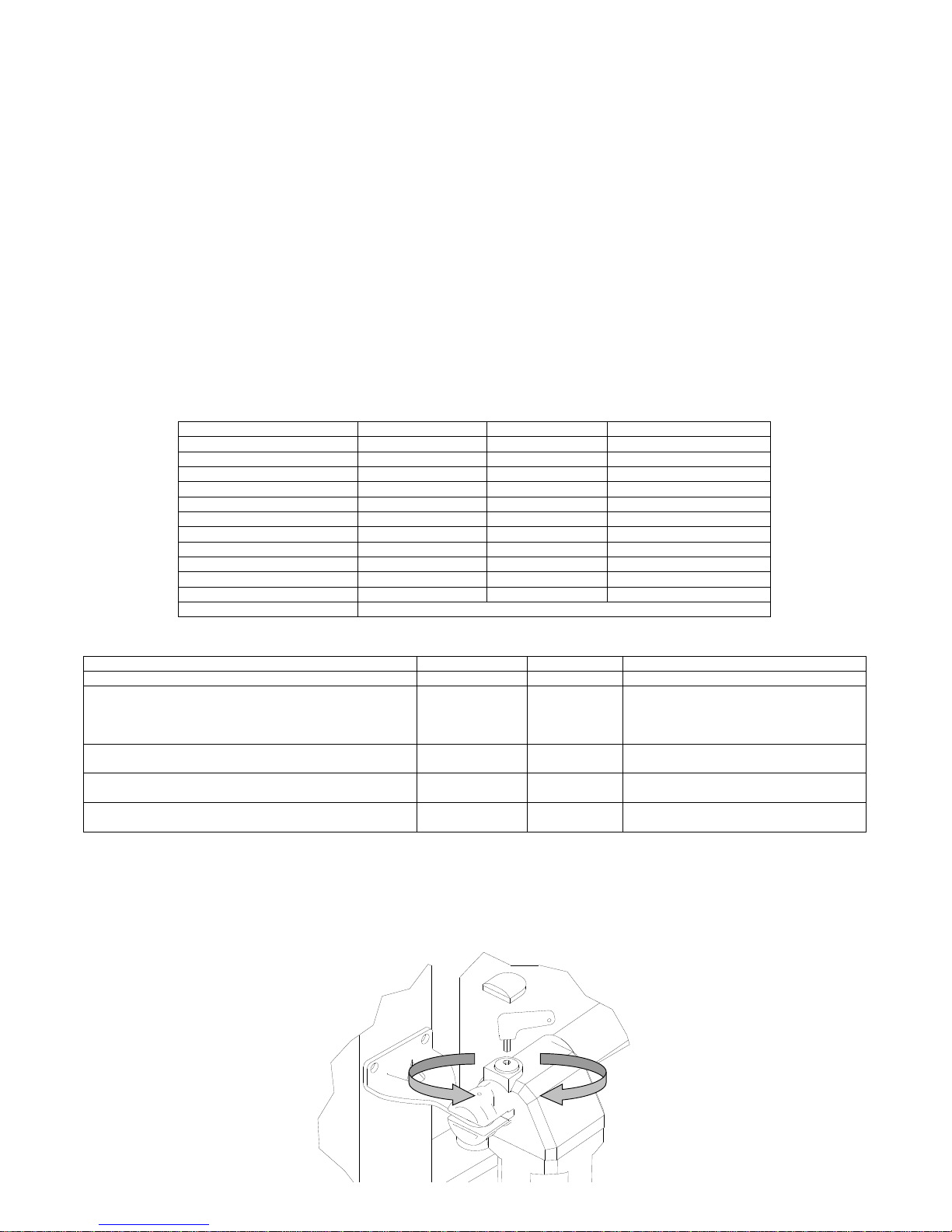
EMERGENCY MANOEUVRE
For the manual door locking and unlocking act with the supplied key on the screw C (See FIG 1-2).
1 - Remove the protection cap
2 - insert the key into the seat allocation as in Figure 1
3 - Turn the key in the sense of the arrow to the top of the gearmotor to unlock and in the opposite block.
STONE 300 GR
STONE 400 GR
STONE 600 GR
Maximum length of the gate
3,0m
4,0 m
5,0 m
Maximum weight of the gate
200Kg
200Kg
200Kg
Stroche
30cm
40cm
60cm
Power
180 W
180 W
180 W
Power supply
220 V
220 V
220V
Absorption
0,9 A
0,9 A
0,9 A
Max. Thrust
1600 N
1600 N
1600 N
Operating temperature
-25°C +60°C
-25°C +60°C
-25°C +60°C
Opening time
17sec.
22sec.
33sec.
Thermal protection
150°C
150°C
150°C
Use frequency
35%
35%
35%
Lubrication
GREASE
ANTICLOCKWISE:
RELEASED
CLOCKWISE:
BLOCKED
FIG 1
IO 18/E Rev. 00
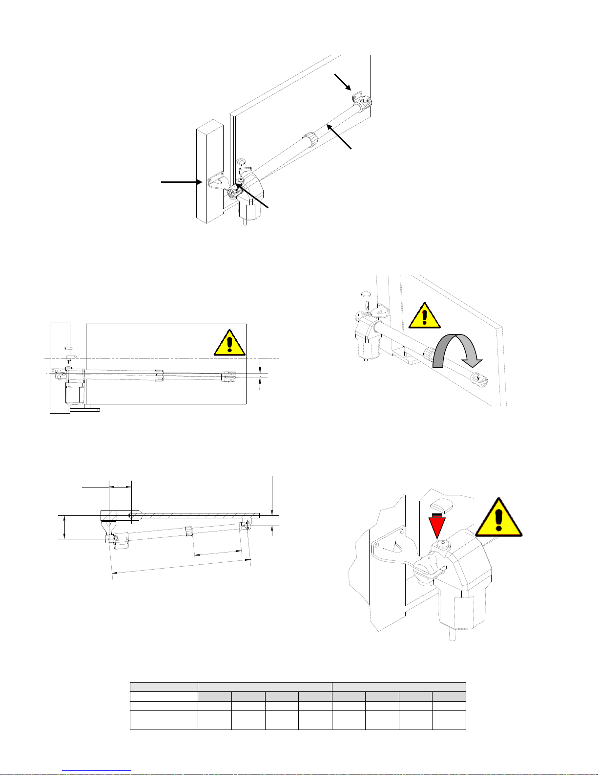
INSTALLATION
INSTALLATION
To operate a good installation of the gear motors STONE 300-400-600
GR, follow these instructions:
1 - Open the box and take out gear motor. Make sure that it has not
been damaged during the transport.
2 - Make sure that the leaf of the gate is perfectly horizontal.
3 - Place the gear motor inclined approximately 1º below the
horizontal line(picture 3 )
1°
4- Fix the support plate A on the pillar beside the leaf, taking in account
the measures shown in Table 1. Do not forget inclination.
1°
Z
W
6.0
Y
X
5 - Install the gear motor on to the support plate A and fix it with the bolt.
6 - With gate’s leaf closed, turn and slide the screw of gear motor’s D
shaft, until the end of the stroke-
7 - Screw D shaft back on 1 complete turn of 360º. (picture5)
8 - Place B support plate in the hole of D shaft and position it against
the gate leaf. Fix it to the gate leaf taking in account the inclination
(point nr.3).
9 - Proceed in the same way with the other gate leaf.
10 - Connect the electrical wires and safety devices: Place the
mechanical limit stops
11 – Place the cover on the unblocking screw (C) (picture 6)
TAB 1
MOTOR
ROTATION 95 °
ROTATION 120 °
W X Y Z W X Y Z
STONE300
922
140
140
378
922
160
120
378
STONE400
1122
145
145
478
1122
170
110
478
STONE600
1532
280
280
678
1532
310
120
678
A
A – Pillar bracket
B – Gate bracket
D – Piston rod
C – Release
FIG 2
360°
FIG 3
FIG 4
FIG 5
FIG 6
IO 18/E Rev. 00
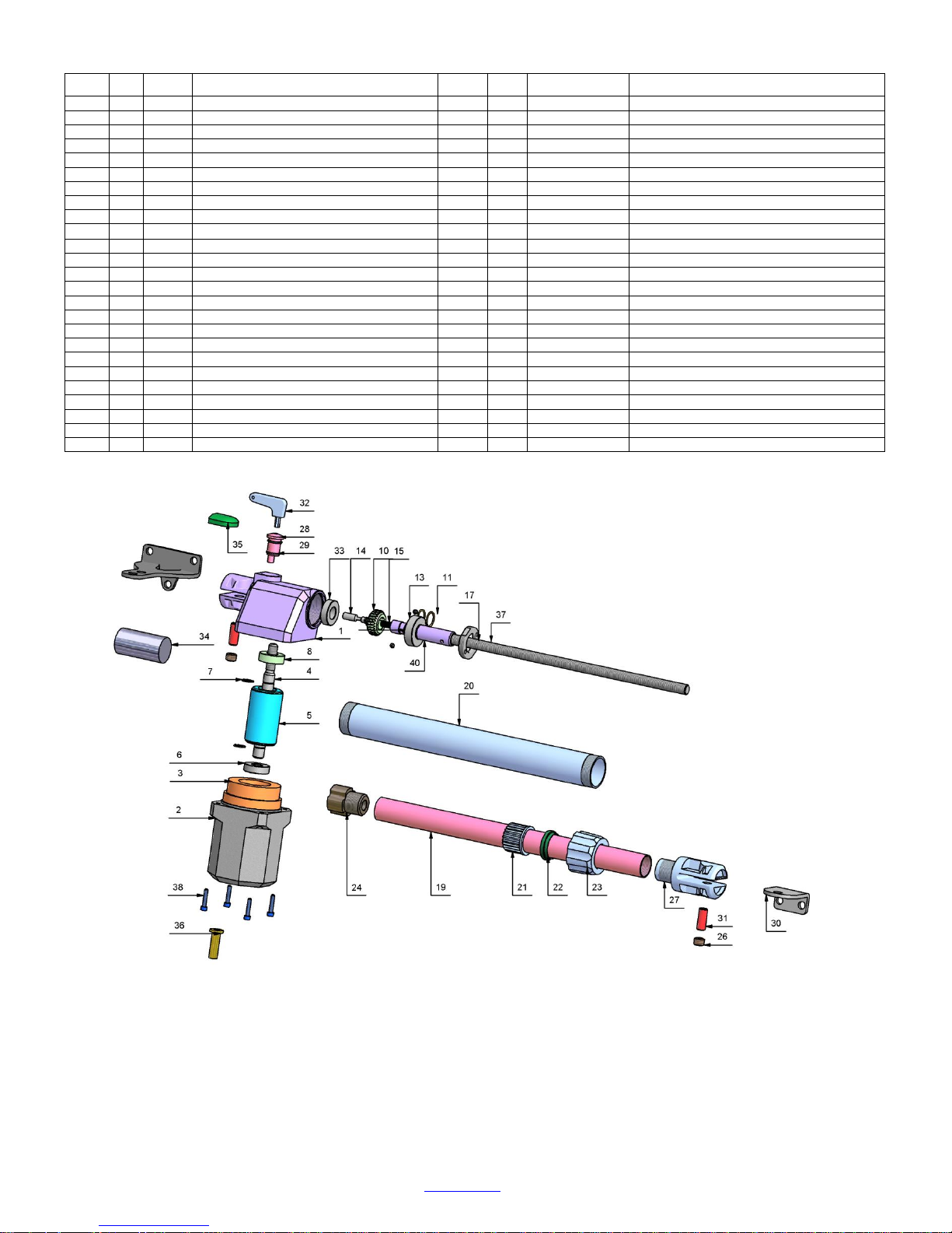
SPARE PARTS
PART
QTy
CODE
DESCRIPTION
PART
Q.TY
CODE
DESCRIPTION
1 1 100645
REDUCTION GEAR COVER LF. BLACK
20 1 100715
BLACK ALUMINIUM TUBE 400mm STROKE
1 1 100644
REDUCTION GEAR COVER RG. BLACK
20 1 100763
GREY ALUMINIUM TUBE 400mm STROKE
1 1 100759
REDUCTION GEAR COVER LF. GREY
20 1 100739
BLACK ALUMINIUM TUBE 600mm STROKE
1 1 100758
REDUCTION GEAR COVER RG. GREY
20 1 100764
GREY ALUMINIUM TUBE 600mm STROKE
2 1 100647
MOTOR CASING RG. BLACK
21 1 100829
PISTON ROD GUIDE
2 1 100761
MOTOR CASING RG. GREY
22 1 100625
SCRAPER RING
3 1 100840
STATOR 220V 4 POLES 45mm 1400rpm
23 1 100827
PISTON ROD LOCK NUT
4 1 100651
IRREVERSIBLE MOTOR SHAFT
24 1 100828
FEMALE SCREW
5 1 100841
ROTOR 45mm
25 1 100823
WALL BRACKET
6 1 100278
BEARING 6202 ZZ
26 2 100705
GRUB SCREW M14X10
7 2 100706
HELASTIC RING E15
27 1 100646
ALUMINIUM PISTON ROD TERMINAL BLACK
8 1 100291
BEARING 6202 2RS
27 1 100906
ALUMINIUM PISTON ROD TERMINAL GREY
10 1 100650
IRREVERSIBLE TOOTH WHEEL
28 1 100624
ALUMINIUM UNCLAMPING
11 2 100789
HELASTIC RING E20
29 2 100657
O-RING
12 1 100709
BEARING 6004 ZZ
30 1 100825
GATE BRACKET
13 2 100658
TOWING BALL
31 2 100654
PIN
14 1 100655
UNCLAMPING PIN
32 1 100218
UNCLAMPING KEY
15 1 100641
UNCLAMPING SPRING
33 1 100707
BEARING 6003 ZZ
17 1 100661
ALUMINIUM LOCK NUT
34 1 100184
CAPACITOR 8µF
17 100909
FIBRE LOCK NUT
35 1 100755
UNCLAMPING CAP
19 1 100712
STAINLESS STEEL TUBE 300mm STROKE
36 1 100748
CABLE PRESS
19 1 100713
STAINLESS STEEL TUBE 400mm STROKE
37 + 40
1
100716 + 100998
ENDLESS SCREW 40 + release shaft
19 1 100738
STAINLESS STEEL TUBE 600mm STROKE
37 + 40
1
100717 + 100998
ENDLESS SCREW 50 + release shaft
20 1 100714
BLACK ALUMINIUM TUBE 300mm STROKE
37 + 40
1
100740 + 100998
ENDLESS SCREW 70 + release shaft
20 1 100762
GREY ALUMINIUM TUBE 300mm STROKE
38 4 100313
CAP SCREW M5X16
CARDIN ELETTRONICA Spa
Via Del Lavoro, 73
31013 Codognè, Fraz. Cimavilla TV
Tel. +39 0438 404011 Fax. +39 0438 401831
www.cardin.it
1
ZVL933.00 Mod: 12-05-2016
ITALIANO
ENGLISH
FRANÇAIS
DEUTSCH
ESPAÑOL
ATTENTION! Before installing this device read the
following instructions carefully!
Conformity declaration Page 2
Important remarks Page 8
Electrical connection Pages 8-9
Programming procedure Pages 10-11
Remote control Page 12
Function modes Page 12
Indications on the display Page 12
Technical specications Page 28
ATTENTION! Avant de commencer la pose, lire attentivement les instructions!
Déclaration de conformité Page 2
Consignes importantes Page 13
Branchement électrique Pages 13-14
Procédé de programmation Pages 15-16
Commande via radio Page 17
Modes de fonctionnement Page 17
Indications de l’afcheur Page 17
Caractéristiques techniques Page 28
ACHTUNG! Bevor mit der Installation begonnen wird,
sollte die Anleitung aufmerksam gelesen werden.
Konformitätserklarung Seite 2
Wichtige Hinweise Seite 18
Elektrischer Anschluss Seiten 18-19
Programmierverfahren Seiten 20-21
Funkbefehl Seite 22
Betriebsmodus Seite 22
Displayanzeigen Seite 22
Technische Eigenschaften Seite 28
¡ATENCIÓN! Antes de iniciar la instalación del sistema,
leer atentamente las instrucciones.
Declaración de conformidad Página 2
Advertencias importantes Página 23
Conexionado eléctrico Páginas 23-24
Procedimiento de programación Página 25-26
Mando vía radio Página 27
Modalidad de funcionamiento Página 27
Indicaciones en el display Página 27
Datos técnicas Página 28
ATTENZIONE! Prima di iniziare l'installazione leggere
le istruzioni attentamente!
Dichiarazione di conformità Pagina 2
Avvertenze importanti Pagina 3
Collegamento elettrico Pagine 3-4
Procedura di programmazione Pagine 5-6
Comando via radio Pagina 7
Modalità di funzionamento Pagina 7
Indicazioni del display Pagina 7
Caratteristiche tecniche Pagina 28
230 Vac Motors
PROGRAMMATORE ELETTRONICO PER IL COMANDO DI PORTE E PORTONI MOTORIZZATI
ELECTRONIC PROGRAMMER CONTROLLING MOTORISED GATES AND DOORS
PROGRAMMATEUR ÉLECTRONIQUE POUR LA COMMANDE DE PORTES ET PORTAILS MOTORISÉS
ELEKTRONISCHER STEUERUNGSEINHEIT FÜR DIE AUTOMATISIERUNG VON TÜREN UND TOREN
PROGRAMADOR ELECTRONICO PARA EL CONTROL DE LAS PUERTAS MOTORIZADAS
Questo prodotto è stato testato e collaudato nei laboratori della casa costruttrice, la quale ne ha verificato la
perfetta corrispondenza delle caratteristiche con quelle richieste dalla normativa vigente. This product has been
tried and tested in the manufacturer's laboratory who have verified that the product conforms in every aspect to
the safety standards in force. Ce produit a été testé et essayé dans les laboratoires du fabriquant. Pour l'installer
suivre attentivement les instructions fournies. Dieses Produkt wurde in den Werkstätten der Herstellerfirma
auf die perfekte Übereinstimmung ihrer Eigenschaften mit den von den geltenden Normen vorgeschriebenen
getestet und geprüft. Este producto ha sido probado y ensayado en los laboratorios del fabricante, que ha
comprobado la perfecta correspondencia de sus características con las contempladas
por la normativa vigente.
Model
Date
Instruction manual
Series
PRG230M2
V0.2
01-04-2016
ZVL593.00
CARDIN ELETTRONICA spa
Via del lavoro, 73 – Z.I. Cimavilla
31013 Codognè (TV) Italy
Tel: +39/0438.404011
Fax: +39/0438.401831
email (Italian): Sales.office.it@cardin.it
email (Europe): Sales.office@cardin.it
Http: www.cardin.it
V. 02.2017
ZVL601
CENTRALE COMANDO PER 1-2 MOTORI 230V
Istruzioni d’uso e di programmazione
CENTRALE DE COMMANDE POUR 1-2 MOTEURS 230V
Notice d'emploi et de programmation
CENTRAL DE MANDO PARA 1 O 2 MOTORES DE 230 V
Instrucciones de uso y programación
ELECTRONIC CONTROL UNIT FOR 1 or 2 230V-MOTORS
Programming and user instructions
STEUERZENTRALE FÜR 1-2 MOTOREN MIT 230V
Gebrauchs- und Programmierungsanweisungen
BESTURINGSKAST VOOR 1-2 230V MOTOREN
Gebruiksaanwijzing en programmeerinstructies
I
F
E
GB
D
NL
mod. T600
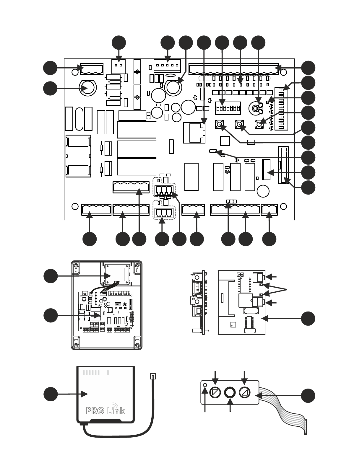
1
2
28
29
P1 (P/P)
STOP*
PA
Spia
PC
P2 (PED)
Led
3 4 5 86 9 10
12
14
15
16
18
19
20
13
17
11
22 21232627 2425
7
Art. XXXOC2
Art. TAST 3F
30
32
31
MEMORIA
Fig. A Fig. B
1
7
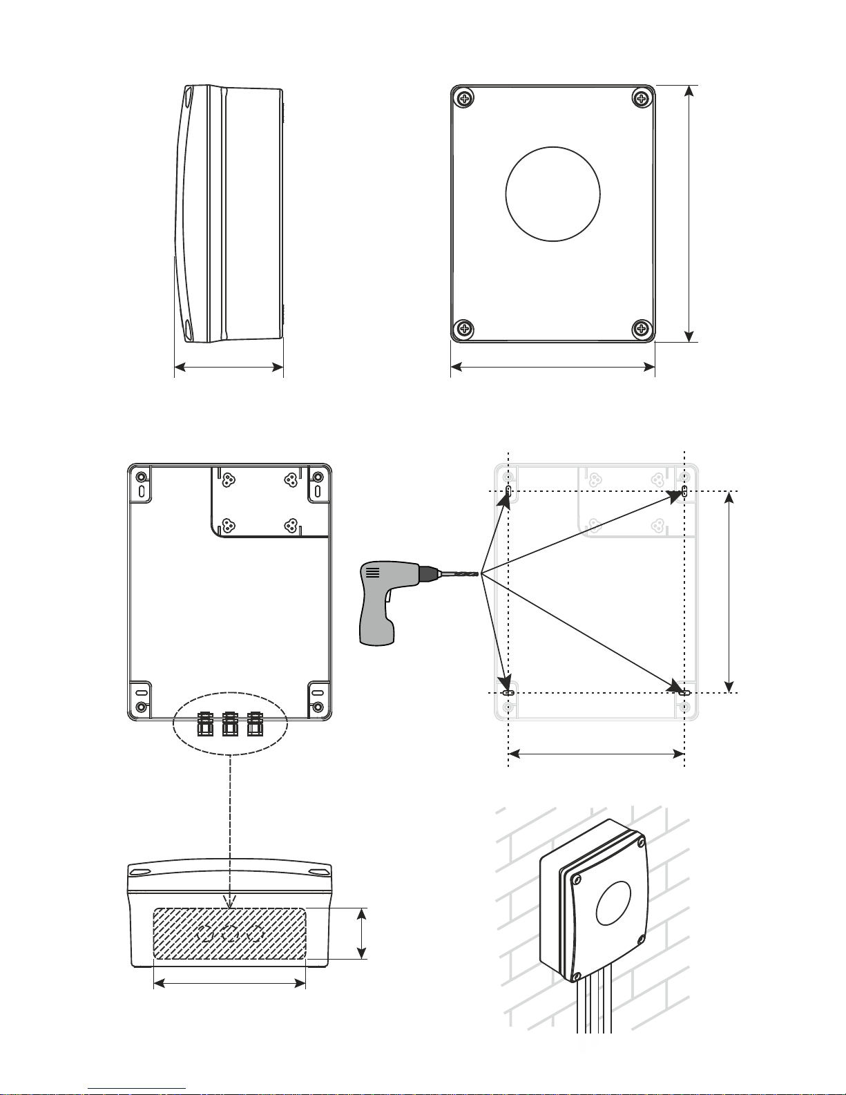
222
190
150
50
118
280
220
(mm)
8
 Loading...