

Telcoma PASSO CARD Series, PASSO CARD Reader, PASSO CARD Receiver Operation And Programming Instructions
Page 1
PASSO CARD
RFID
LETTORE DI DISPOSITIVI TAG
I
Istruzioni d’uso e di programmazione pag. 5
LECTEUR DE DISPOSITIFS TAG
F
Instructions pour l'utilisation et la programmation pag. 14
LECTOR DE DISPOSITIVOS TAG
E
Instrucciones de uso y de programación pag. 23
TAG DEVICE READER
GB
Operation and programming instructions pag. 32
TAG-LESEGERÄT
D
Gebrauchs- und Programmierungsanleitung pag. 41
ISTPASSOCARD
V. 01.2013
LEZER VOOR TAG's
NL
Gebruiks- en programmeeraanwijzingen pag. 50
Page 2
F E GB D NL
II
Fig. 1
1
2
1 234
12/24
A B
Vdc/ac
3
4
5
Fig. 2
6
12V 24V
LINEA
2
Page 3
F E GB D NL
II
Fig. 3
3
2
L1
P1
1 2
1
OUT1
3
OUT2
4
P2
5
678
4
A B
5
12/24
Vdc/ac
6
LINEA
12V 24V
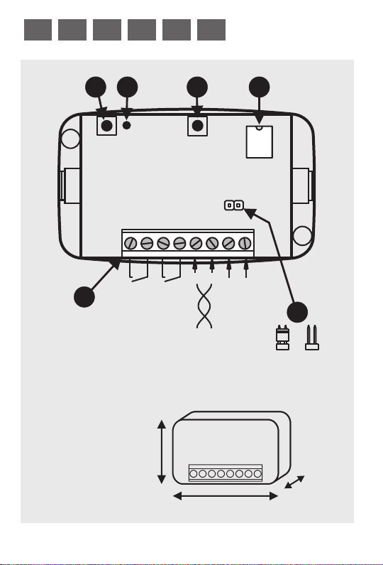
48 mm
box (external dimensions)
3
79 mm
22 mm
Page 4
F E GB D NL
II
Fig.4
L1
P1
P2
5
3
6 7 8
4
112
A B
OUT1
OUT2
12/24
Vdc/ac
3
1
2
4
A B A B
2
3
1
2
4
4
3
1
2
4
A B A B
1
3
3
2
4
4
Page 5

GB
CHARACTERISTICS
In this specific case, an RFID system consists of three fundamental items:
1) one or more transponders (or TAGs)
2) a reading and/or writing device (reader).
3) a data interface or decoder.
The PASSO CARD system allows relays to be activated by RFID (Radio
Frequency IDentification) by just passing the transponder (CARD) close
to the reader.
It can be used in all device control installations, with the following
advantages:
- quick operation and no contact, unlike a conventional key-switch.
- no need for batteries in the portable devices (TAGs).
- serial connection between the CARD reader and the internal unit with
the relay, increasing security and preventing activation through tampering
with the reader.
- option of combining PASSO CARD readers and PASSO digital keypads
in the same system.
- The system is protected from unauthorised programming and only
PASSO series devices and accessories are enabled within it.
The reader (fig.1) is a protected device with integral antenna, for
installation in a point accessible to users. It has a warning buzzer and a
LED light on the front for easy identification in the dark.
The receiver unit (fig.3) has two clean-contact relay outputs, each of
which can be programmed as follows:
- Jog (relay activated for one second)
- Stepping
- Timed 30” (programmable from 2 to 255 seconds with PASSOTS)
32
Page 6

GB GB
TECHNICAL SPECIFICATIONS
PASSO CARD M.U. R Receiver
Power supply Vac/Vdc 12/24 12/24
Consumption (at 24Vac) mA 100 120
Relay contacts max. current A - 1
Relay contacts max. voltage Vac - 24
Connection line max. distance m 200
Transmission speed baud 38.400
No. of possible memorised codes nr. - 750
Max. number of receiver nr. 4 Operating temperature °C -20+55 -20+55
Protection class IP 54 20
Dimensions mm 102x43x34 79x48x21
readers on
eader
PARTS DESCRIPTION
R
EADER
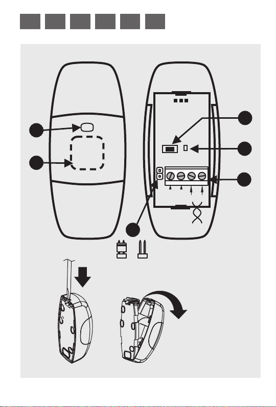
Fig. 1)
Indicator LED
1.
2. Internal antenna
utton
3. B
4. LED
Terminal
5.
6. V
oltage selector
Fig. 2) Reader opening
33
RECEIVER
Fig. 3)
Terminal
1.
utton
2. P1 B
3. LED L1
utton
4. P2 B
emory
5. M
oltage selector
6. V
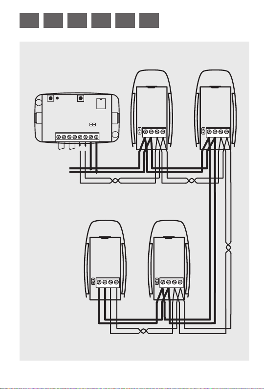
Fig. 4) Connection example with
4 activation devices.
Page 7

INSTALLATION
Find a position for the reader which is easily accessible to the user, while
the receiver should be installed indoors, in a protected position.
Remove the lid of the reader with the aid of a screwdriver (fig. 2) and fix
the bottom firmly, in a vertical position (the closing clip must be at the top).
Connect terminals 1-2 of the readers and 7-8 of the receiver to a 12 or 24V
power supply. Check that the voltage change jumper (6 in fig. 1 and 2) is
only connected with power supply at 12V.
Check the communication line between the readers (terminals 3 - 4 fig. 1)
and the receiver (terminals 5 - 6 fig. 3).
In multiple systems, up to 4 control units (PASSO TS keypads or CARD
readers) can be used to activate the same receiver; in this case there will
be a single communication line, parallel-connecting all the circuit boards
as shown in fig.4.
Warning! use twisted cable for the data line, complying
with the references. The reader (or keypad) terminals
(A) must be connected to the terminal (A) of the
receiver, and the terminals (B) to (B) of the receiver.
Connect the devices to be controlled to the receiver outputs (terminals 1 2 and/or 3 - 4 in fig. 3).
PROGRAMMING
Two types of CARD are supplied with each PASSO reader:
- MASTER CARD: this is the “key” for access to the programming and/or
deletion of codes in readers.
In a new system, the MASTER CARD is the first to be memorised, and a
34
Page 8

GB GB
second one (optional) may also be added.
- USER CARD: this is the tag used to activate the receiver channel.
Each CARD sold has a different code, which can only be saved with the
aid of the MASTER CARD. Two or more USER CARDS can be copied
with the aid of the PRG CARD programmer.
Saving the MASTER CARD
In a new system (with no Master code in the memory), as soon as the
reader is powered up, beeps will be heard. Place the MASTER CARD
next to the reader to acquire the code and stop the beeps.
The same MASTER CARD can be saved on several readers.
To enter the second MASTER CARD:
- place the first MASTER CARD next to the reader; it will start emitting
beeps
- place the new MASTER CARD for memorisation next to the reader; it
will confirm the operation by giving a double beep.
*WARNING! Take good care of all the MASTER CARDS and keep
them in a safe place. MASTER CARDS cannot be replaced or deleted
from the reader, and if they are lost no further programming is
possible.
Saving the USER CARDS
The MASTER CARD memorised is required for this operation.
Basic principle: passing the MASTER CARD over the reader once or
more sets the future operating mode of the USER CARDS about to be
saved.
Procedure for activating new USERS on relay 1 (OUT 1) of the receiver:
- pass the MASTER CARD over the reader once
- a series of single flashes of the LED on the front, and beeps, will start
- pass the new USER CARD to be memorised over the reader; a flash and
a longer beep confirm that the code has been acquired*
- proceed to memorise more cards, or wait for the LED to stop flashing.
Procedure for activating new USERS on relay 2 (OUT 2) of the receiver:
35
Page 9

- pass the MASTER CARD over the reader twice
- a series of double flashes of the LED on the front, and beeps, will start
- pass the new USER CARD to be memorised over the reader; a flash and
a longer beep confirm that the code has been acquired*
- proceed to memorise more cards, or wait for the LED to stop flashing.
(*) A series of 8 beeps and flashes of the LED indicates that the code is
already in the memory.
Procedure for deleting a USER CARD
- pass the MASTER CARD over the reader 4 times
- a series of 4 flashes of the LED on the front, and beeps, will start
- pass the USER CARD to be deleted over the reader; a flash and a longer
beep confirm that the code has been deleted
- proceed to delete more cards, or wait for the LED to stop flashing.
CLEARING THE RECEIVER MEMORY
WARNING! This procedure deletes all the codes in the receiver
memory.
Any PASSO digital keypads connected to this receiver will be
restored to their default condition, with MASTER code 1-2-3-4-5-6-7-
8.
Procedure: hold down button P1 on the receiver for about 10 seconds
until the red LED L1 lights up (det. 2 and 3 in fig. 3).
This operation does not delete the MASTER CARDS.
36
Page 10

GB GB
CHANGING THE OUTPUT OPERATING MODE
The receiver outputs are able to operate in one of the following modes:
PULSE: the relay is activated for about 1 second whenever it reads a
card.
STEPPING: the first time the card is passed the relay closes the contact
and it remains active until the next time a code present in the memory is
read.
TIMER: in this mode, when a code present in the memory is read, the
output is activated for 30 seconds.
If the system includes a PASSO keypad, the timer time setting can be
modified from 2 to 255 seconds (see PASSO manual).
The mode selected refers to the individual output; all the codes saved
previously or subsequently will have the operating mode chosen.
Procedure:
- Press the reader button and the red LED comes on (det. 3 and 4 in fig.
1).
- Pass the MASTER CARD over the reader and the LED will start to
flash.
- Press the button (det. 3 in fig. 1) several times to choose one of the
following settings:
1 Flash = to set OUT1 in PULSE mode.
2 Flashes = to set OUT1 in STEPPING mode.
3 Flashes = to set OUT1 in TIMER mode (30”).
4 Flashes = to set OUT2 in PULSE mode.
5 Flashes = to set OUT2 in STEPPING mode.
6 Flashes = to set OUT2 in TIMER mode (30”).
- Pass the MASTER CARD over the reader to confirm and quit the
programming function.
37
Page 11

OPERATION AND SIGNALS
Pass the CARD over the reader to activate the devices.
If the LED (DET. 1 in fig. 1) goes out for a moment and/or a beep is heard,
the CARD is in the memory and the receiver has activated the associated
output.
A sequence of 4 beeps and LED flashes, after a CARD is read, indicate
that the code read is not in the memory, and the receiver will not activate
either output.
A sequence of 10 beeps and LED flashes, after a CARD is read, indicate
that the communication line to the receiver has failed.
The MASTER CARDS are only enabled for programming functions and
cannot be used to activate devices directly.
MODIFICATIONS OR REPLACEMENTS IN THE
SYSTEM
To replace a reader (in the event of a failure) or add another to the
receiver, proceed as follows:
- Make the connections as described in the installation section.
- Memorise the MASTER CARD
The USER codes will not be lost because they are retained in the receiver
part.
If the receiver part is replaced, to avoid losing all the codes saved, remove
the memory (det. 5 in fig. 3) from the old receiver and fit it in the new one.
38
Page 12

GB GB
FINAL ADVICE
Do not perform any wiring or modifications to the connections prior to
having isolated the power supply.
Cards must be looked after carefully and protected from damage; do not
bend or make holes in them, and do not place them to powerful
electromagnetic sources.
The non-observance of the said instructions could prejudice the correct
function of the equipment.
TELCOMA decline any responsibility for possible malfunction and/or
damage due to their non-observance.
TELCOMA srl reserve the right to make modifications at any time they
deem necessary in order to improve the aesthetical and/or functional
aspect of the product.
GUARANTEE
The present guarantee covers possible faults and/or irregularities due to
manufacturing defects and/or faults.
The guarantee will automatically expire in the event of tampering or
misuse of the product.
During the guarantee period TELCOMA srl pledge to repair and/or
replace defective and non-tampered parts. The call charges, as well as
the collection, packaging and transportation costs of the product for repair
or replacement are at the clients full and exclusive expense.
39
Page 13
DISPOSAL
This product is made up of various parts that could contain polluting
substances.
Avoid release to the environment!
Enquire about the local recycling or disposal systems in
compliance with present laws and regulations.
EC DECLARATION
The undersigned, , legal representative of TELCOMA
Address: Via L. Manzoni 11, Z.I. Campidui - 31015 Conegliano (TV)
Is in accordance with the essential requirement of Directive 89/336
(EMC: EN 61000-6-3 + EN 61000-6-1) and subsequent modifications,
Is in accordance with the essential requirement of Directive 73/23
(LVD) 60335-1 standard and subsequent modifications, if implemented
Place and date, 01/02/2013
Ennio Ambroso
S.r.l.,
ITALY
Declares that the product PASSO CARD,
used as a selector for gate automations
if implemented for the said use.
for the said use.
Legal representative
Ennio Ambroso
40
Page 14

Telcoma s.r.l.
via L. Manzoni, 11 z.i. Campidui
31015 Conegliano (TV) Italy
Tel. +39 0438-451099 - Fax +39 0438-451102
http://www.telcoma.it E-mail:info@telcoma.it
 Loading...