

Page 1
K100
ISTRUZIONI PER L’INSTALLAZIONE DELLA CENTRALINA ELETTRONICA K 100 (PA G .1)
I
IL PRESENTE LIBRETTO È DESTINATO AL PERSONALE TECNICO QUALIFICATO ALLE INSTALLAZIONI
INSTRUCTIONS POUR L’INSTALLATION DE LA CENTRALE ELECTRONIQUE K 100 (PA G .9)
F
CETTE NOTICE S’ADRESSE À DES TECHNICIENS SPÉCIALISÉS DANS L’INSTALLATION
INSTRUCCIONES DE LA CENTRAL ELECTRONICA K 100 (PA G . 17)
E
EL PRESENTE FOLLETTO ESTÁ DESTINADO AL PERSONAL TÉCNICO ESPECIALIZADO EN INSTALACIONES
INSTRUCTIONS FOR INSTALLING THE ELECTRONIC CONTROL UNIT K 100 (PA G . 25)
GB
THIS HANDBOOK IS INTENDED FOR QUALIFIED TECHNICAL INSTALLERS
INSTALLATIONSANWEISUNGEN DER ELEKTRONISCHEN STEUEREINHEIT K 100 (PA G . 33)
D
DAS VORLIEGENDE HANDBUCH IST FÜR DAS MIT DER INSTALLATION BETRAUTE TECHNISCH
QUALIFIZIERTE FACHPERSONAL BESTIMMT
V. 11.2006
AANWIJZINGEN VOOR DE INSTALLATIE VAN DE ELEKTRONISCHE BESTURINGSKAST K 100 (PA G . 41)
NL
DEZE HANDLEIDING IS BESTEMD VOOR VAKBEKWAME INSTALLATEURS
Telcoma srl - Via L. Manzoni, 11 - Z.I. Campidui - 31015 Conegliano - (TV) Italy
Tel. +39 0438-451099 - Fax +39 0438-451102 - Part. IVA 00809520265
http://www.telcoma.it E-mail: info@telcoma .it
Page 2

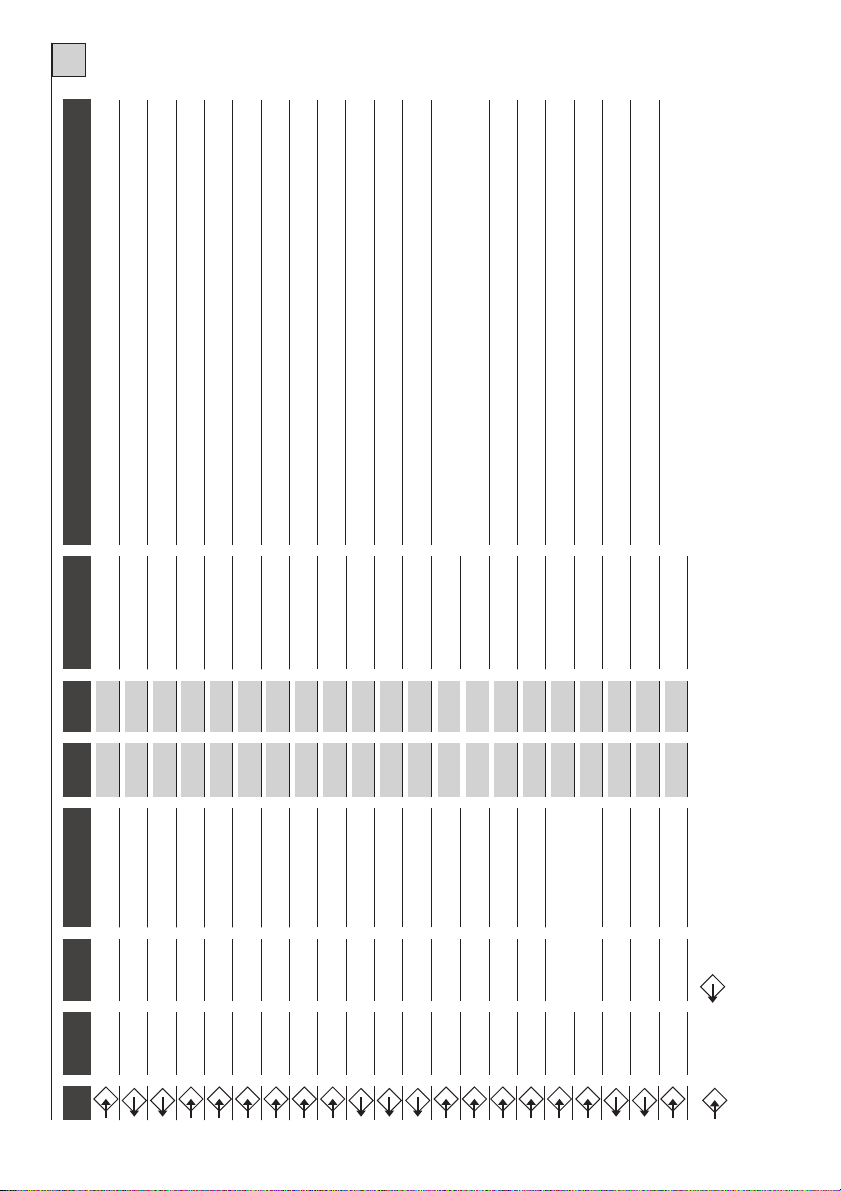
Fig. 1 / Abb. 1
2
Page 3

* ANTENNA: se viene usata una scheda radio ad innesto prestare attenzione in quanto su alcuni modelli il connettore
per il collegamento dell’antenna è sulla scheda stessa.
* ANTENNE: être attentif dans le cas d'utilisation d'une fiche radio embrochable dans la mesure où, sur certains modè-
les, le connecteur permettant de raccorder l'antenne se trouve sur la fiche même.
* ANTENA: Si se utiliza una tarjeta radio de acoplamiento, hay que prestar atención ya que, en algunos modelos, el
conector para la conexión de la antena se encuentra en la misma tarjeta.
* ANTENNA: pay attention if a plug-in radio card is used, since the connector for antenna connection in certain models
is on the actual card.
* ANTENNE: wenn eine Steckfunkplatine verwendet wird, ist darauf zu achten, daß sich der Verbinder für denAnschluß
an die Antenne bei einigen Modellen auf der Platine selbst befindet.
* ANTENNE:Als er een inplugontvanger toegepast wordt moet er opgelet worden omdat bij sommige modellen de con-
nector voor de aansluiting van de antenne op de kaart zelf geplaatst is.
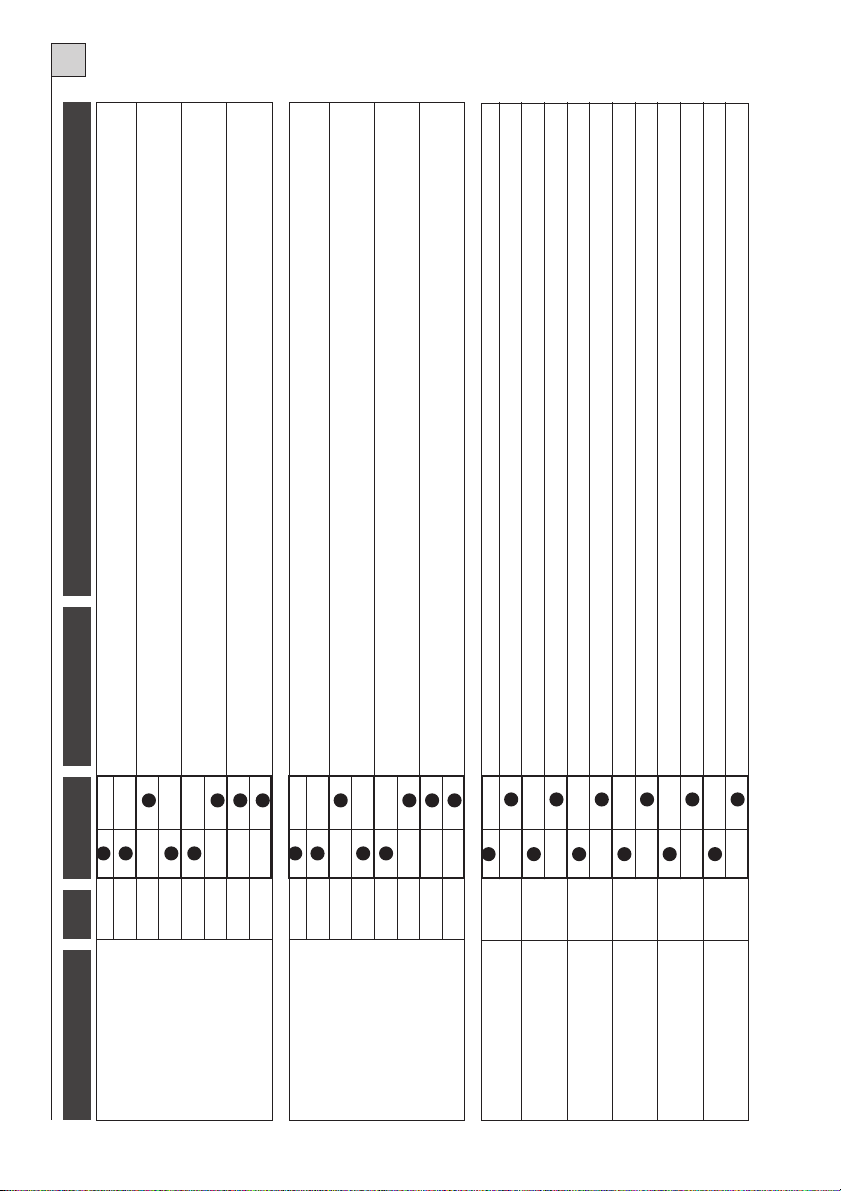
Fig. 2 / Abb. 2
3
Page 4

ISTRUZIONI PER L’INSTALLAZIONE DELLA CENTRALINA ELETTRONICA K100
I
Prima di eseguire l’installazione consigliamo di leggere attentamente la presente istruzione.
Un uso improprio del prodotto o un errore di collegamento potrebbe pregiudicare il corretto funzionamento dello stesso e la sicurezza dell’utente finale.
DESCRIZIONE DELLE PARTI (Fig. 1)
1) Pulsante PP Passo/Passo
2) Pulsante STOP/PROG per Programmazione e
Stop*
3) Scheda radio incorporata
4) Dip-switch funzioni
5) Trimmer per regolazione potenza motore
6) Jumper Jp1 (esclusione regolazione potenza
motore e soft-start)
7) Morsettiera collegamenti in bassa tensione 24 V
8) Reset centralina. Cortocircuitare per un attimo i
2 pin equivale a togliere e ridare la tensione.
9) Led di segnalazione relativi agli ingressi in morsettiera. Led acceso = ingresso chiuso
10) Led Programmazione (L1)
11) Morsettiera collegamenti a 230 V
* Questo pulsante di STOP non deve essere considerato di sicurezza ma solo di servizio per facilitare
i test durante l’installazione.
12) Fusibile linea 6,3 A
13) Morsettiera collegamento motore e condensatore
14) Morsettiera collegamento primario trasformatore
15) Scheda opzionale antischiacciamento (MAS 100)
16) Fusibile 24 V 0,3 A
17) Morsettiera collegamento secondario trasformatore
18) Morsettiera collegamento finecorsa
19) Trimmer per la regolazione tempo di rallentamento (solo su alcune versioni)
MODELLI
Descrizione modelli della centrale K100:
K100: :centrale per l'automazione di 1 motore, ricevitore incorporato serie TANGO
K100 SW: centrale per l'automazione di 1 motore, ricevitore incorporato serie TANGO SW
Le centraline sono dotate di:
- regolazione elettronica della coppia
- rallentamento motore
- freno motore
- autodiagnosi del controllo motore (Triac Test)
- sistema antischiacciamento (modulo opzionale MAS 100)
Note importanti:
La centrale K100 non è adatta a comandare motori con condensatore e finecorsa già cablati direttamente
all'interno del motore stesso (es. motori per serrande).
Non usare la funzione di rallentamento con i motori oleodinamici.
Il cancello deve sempre avere dei fermi meccanici (battute di arresto).
4
Page 5

I
DATI TECNICI
Parametri elettrici
Frequenza
Assorbimento stand-by
Modello trasmettitore per centrale K100
U.M.
Va cAlimentazione 230 ±10%
Hz
mA
AAssorbimento massimo
VAPotenza max motore
°Ctemperatura funzionamento
mmDimensione scheda (L x H x P)
serie
serieModello trasmettitore per centrale K100 SW
MHzFrequenza di ricezione
NrCapacità di memorizzazione codici
K100
50
20
6,3
1100
-20 +60
92x50x161
Tango
Tango SW - BLEU
433.920
140
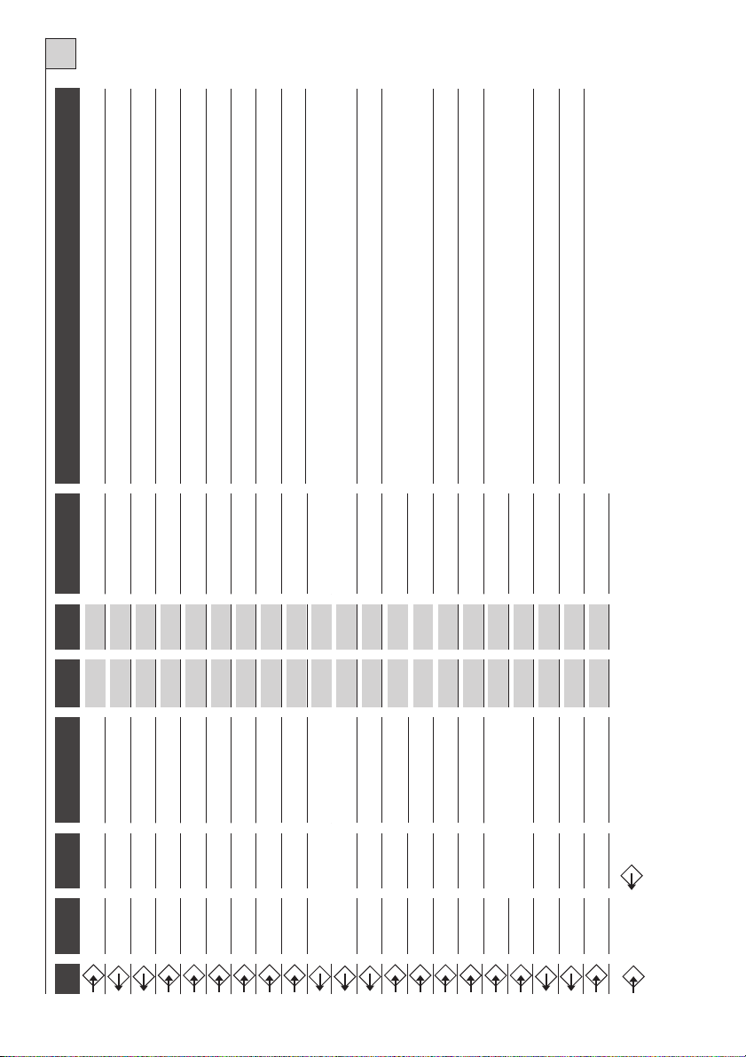
COLLEGAMENTI ELETTRICI
Per i collegamenti seguire la tabella 1 e la figura 2.
Nel caso di impianti già esistenti è opportuno un controllo generale dello stato dei conduttori (sezione,
isolamento, contatti) e delle apparecchiature ausiliarie (fotocellule, riceventi, pulsantiere, selettori chiave,
ecc.).
Consigli per un corretto impianto:
1) Le condutture entranti nella centralina, nella versione su box stagno, devono essere installate mantenendo possibilmente invariato l’iniziale grado di protezione IP56.
2) La sezione dei cavi deve essere calcolata in base alla loro lunghezza e corrente assorbita.
3) Non usare un cavo unico del tipo “multi-polo” per tutti i collegamenti (linea, motori, comandi, ecc.) o in
comune con altre apparecchiature.
4) Dividere l’impianto in almeno due cavi, ad es.:
Cavo (A) sezione minima conduttori 1.5 mmq
- linea alimentazione - linee motori - linea lampeggiante / luce cortesia
Cavo (B) sezione minima conduttori 0.75 mmq
- alimentazioni ausiliari - comandi - contatti sicurezza
5) Quando i cavi di comando presentano tratte molto lunghe (oltre i 50 metri) è consigliabile il disaccoppiamento con dei relè montati vicino alla centralina.
6) Tutti gli ingressi N.C. (fotocellule, finecorsa, costa-fissa e stop) che nella centralina non vengono utilizzati devono essere cortocircuitati con il comune.
7) Tutti i contatti N.C. abbinati ad uno stesso ingresso devono essere collegati in serie.
8) Tutti i contatti N.A. abbinati ad uno stesso ingresso devono essere collegati in parallelo.
- Per l’alimentazione della centralina è previsto L’INSERIMENTO DI UN SEZIONATORE esterno (non
in dotazione) indipendente e dimensionato secondo il carico.
- L’INSTALLAZIONE dell’apparecchiatura deve essere effettuata a “REGOLA D’ARTE” da personale
avente i requisiti richiesti dalle leggi vigenti e seguendo normative EN 12453 e EN 12445 riguardanti
la sicurezza dell’automazione.
5
Page 6
I
NOTE
TAB.1
a. Funzione presente su
inuti dopo la chiusura complet
egamento dell’antenna è sulla scheda stessa.
libera la fotocellula. Il comando rimane memoriz-
aa3m
Accesa da inizio manovr
Collegare alla linea 230V.
Si accende durante il movimento del motore.
Avvia l’apertura del cancello.
alcune versioni.
FUNZIONE
IIndicazione movimento
Luce di cortesia
Alimentazione
I max
5A
1A
1A
V
230Vac
230Vac
230Vac
DISPOSITIVO
Linea
Lampeggiante
Lampada
MOR. n.
4
2
4
Pulsante apre
Pulsante N.A.
12
i1e2.
Avvia la chiusura del cancello.
Vedi tabella 2, funzion
Pulsante chiude
Pulsante passo passo
Pulsante N.A.
Pulsante N.A.
12
12
i3e4.
Blocco di tutte le funzioni. Collegare questo ingresso con il comune se non viene utilizzato.
Vedi tabella 2, funzion
Ingresso Jolly
Pulsante stop
Pulsante N.C.
Pulsante N.A. o N.C.
12
12
la chiusura del cancello inverte la marcia. Collegare questo ingresso con il
Segnala con lampeggi differenti lo stato del cancello.
Durante
Alimentazionie fotocellule o altri ausiliari.
comune se non viene utilizzato.
Segnalazione
Fotocellula**
Alim. 24 V
2Wmax
300mA
24Vac
24Vac
Spia cancello aperto
Contatto N.C.
Ausiliari
14
12
14
Uscita ausiliaria con contatto libero. Funzione presente su alcune versioni.
collegata una ricevente al connettore predisposto vedere le caratteristiche dell’antenna
Per la ricevente incorporata utilizzare un’antenna accordata a 433MHz. Nel caso venga
Uscita ausiliaria
Calza
0,5A
max24V
Uscita ausiliaria
Antenna Rx*
17
Collegare questo ingresso con il comune se non viene utilizzato
Collegare questo ingresso con il comune se non viene utilizzato
richieste dal costruttore.
Centrale
Finecorsa apre
Contatto N.C.
Antenna Rx*
21
Collegamento al secondario trasformatore
Finecorsa chiude
Connettore
Contatto N.C.
21
25-26
Collegamento al primario trasformatore
Max 1100VA. Il morsetto 30 è il comune motore.
Max 1100VA. Il morsetto 30 è il comune motore.
Apertura
Chiusura
5A
5A
230Vac
230Vac
Motore
Motore
Connettore
28
30
30
motore!
ATTENZIONE! Collegare il condensatore sempre su questi morsetti e non in parallelo al
Spunto
Condensatore
Uscita
33
MOR. n.
1
3
5
6
7
8
9
10
6
15
16
18
19
11
13
20
22
27
23-24
29
31
32
Entrata
zato nella K100 per 10 secondi, e visualizzato dall’accensione del lampeggiante.
** A fotocellula oscurata e cancello chiuso, se viene inviato un comando, la centrale non esegue l'apertura sino a quando non si
* ANTENNA: se viene usata una scheda radio ad innesto prestare attenzione in quanto su alcuni modelli il connettore per il coll
Page 7
I
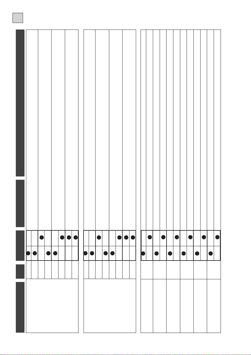
NOTE
TAB.2
Durante la chiusura premendo il pulsante P/P il cancello si blocca, premendo nuovamente apre.
Durante la chiusura premendo il pulsante P/P il cancello si blocca per pochi secondi e poi apre.
Durante l’apertura premendo il pulsante P/P il cancello si blocca per pochi secondi e poi chiude.
Durante l’apertura premendo il pulsante P/P il cancello si blocca, premendo nuovamente chiude.
Durante l’apertura premendo il pulsante P/P non abbiamo nessun effetto. Durante la pausa premendo
DESCRIZIONE
Apre
Apre - Chiude
Apre - Stop - Chiude
OFF ON
1
21212
n.Dip
FUNZIONE
Modo Ingresso
Passo / Passo
Canale Radio
Durante l’apertura premendo il pulsante P/P non abbiamo nessun effetto. Durante la pausa premendo il pulsante P/P il
si blocca per pochi secondi e poi apre.
il pulsante P/P non abbiamo nessun effetto. Durante la chiusura premendo il pulsante P/P il cancello
Chiude
-
Funzione condominiale
Apre
1
cancello chiude. Durante la chiusura premendo il pulsante P/P il cancello si blocca per pochi secondi e poi apre.
Escluso comando in apertura
2
tralina si blocca, la richiusura viene annullata. Usare un contatto N.C.
Un intervento costa fissa inverte la marcia per pochi secondi. Dopo un intervento costa fissa la cen-
Costa Fissa
343
do non si riapre il contatto. Usare un contatto N.A.
Chiudendo l’ ingresso cortocircuitato verso il comune il cancello si apre e rimane aperto fino a quan-
Sia In apertura che in chiusura l’intervento di questa fotocellula blocca il cancello fino a quando non
Orologio
434
Modo Ingresso
viene ripristinata. La manovra successiva è sempre un’apertura. Usare un contatto N.C.
Il cancello esegue un’apertura parziale per un tempo fisso pari a 6 secondi.
Usare un pulsante N.A.
Pedonale
Fotocellula
3
4
Jolly
Il lampeggiante viene alimentato contemporaneamente con il motore.
Dopo una apertura completa la centrale richiude solo con un comando manuale.
Dopo una apertura completa la centrale richiude dopo il tempo pausa programmato.
Il lampeggiante viene alimentato 5 secondi prima di ogni manovra.
Escluso
Inserito
Escluso
Inserito
6
5
Richiusura
Prelampeggio
Funzione esclusa
L’intervento della fotocellula riduce il tempo di pausa, qualunque sia stato il suo valore,a2secondi.
Escluso
Inserito
7
Richiusura dopo fotocellule
Dove non è strettamente necessario è consigliabile escludere il freno.
Il freno motore serve a vincere l’inerzia di automazioni pesanti. Quando il freno è abilitato interviene ad ogni fine manovra.
Escluso
Inserito
8
Freno
Non viene eseguito il rallentamento nella parte finale della corsa.
Con il rallentamento inserito il motore in prossimità di ogni fine manovra dimezza la sua velocità.
Escluso
Inserito
9
Rallentamento
Quando NON viene usata la ricevente incorporata, SI deve escluderla.
Abilitazione della ricevente incorporata.
Escluso
Inserito
10
Radio incorporata
Nota: la configurazione iniziale standard è raffigurata nel part. 4 di fig. 1
7
Page 8

I
PROGRAMMAZIONE TEMPI LAVORO E PAUSA
La centrale auto-apprende i tempi di lavoro e pausa durante la manovra di programmazione.
Durante la fase di programmazione si azionerà più volte il comando P/P (part. 1 di fig. 1), in alternativa si
può usare il comando PP (morsetto 8 di fig. 2 oppure il telecomando (se memorizzato).
Si possono riassumere due tipologie di impianto e modalità diverse:
1) Impianto con finecorsa elettrici.
Durante la programmazione l’intervento del finecorsa determina il limite di manovra del cancello. Seguire
la tipologia 1 per la programmazione.
2) Impianto senza finecorsa elettrici.
Durante la programmazione l’intervento della scheda antischiacciamento (se inserita) determina il limite
di manovra del cancello. Seguire la tipologia 1 per la programmazione.
- Nel caso non vi siano i finecorsa elettrici e la scheda antischiacciamento inserita, i tempi devono
essere impostati mediante l’azionamento del comando P/P. Seguire la tipologia 2 per la programmazione.
Note importanti prima della programmazione:
A.Alimentare la centrale e verificare il corretto funzionamento degli ingressi comando tramite i relativi led (i
contatti nc. devono avere il led acceso).
B.Liberare la zona di movimento del cancello
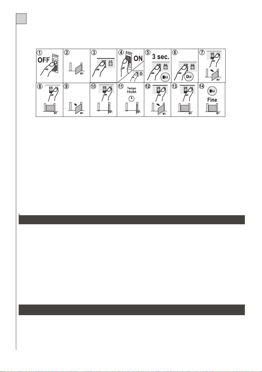
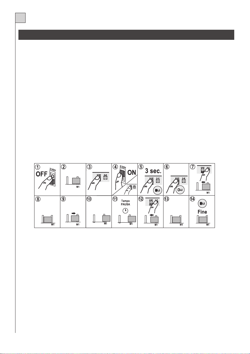
Programmazione: Tipologia 1
AUTOMAZIONE CON FINECORSA ELETTRICI
1) Togliere alimentazione alla centrale.
2) Portare il cancello o il portone a metà corsa.
3) Premere il tasto STOP/PROG.
4,5,6) Alimentare la centrale tenendo premuto il tasto STOP/PROG. (part.2 di fig.1) per almeno 3 sec. Si
accende il led programmazione L1.
(La stessa funzione può essere fatta premendo il tasto STOP/PROG, cortocircuitando per un attimo i
pin reset e tenendo premuto il tasto STOP/PROG sino a quando si accende il led L1).
7) Premere il pulsante P/P (part.1 di fig.1). Il motore inizia una manovra di chiusura. Se il motore gira al
contrario, togliere l’alimentazione, girare le fasi del motore e del finecorsa e ripetere la procedura.
8,9)Arrivato a finecorsa il motore si ferma e parte automaticamente in apertura.
10) Completata l’apertura il motore si ferma.
11) La centralina inizia a contare il tempo di pausa.
12) Trascorso il tempo di pausa desiderato premere il pulsante P/P e il motore inizia la chiusura.
13) Arrivato a finecorsa di chiusura il motore si ferma.
14) Fine della programmazione il led L1 si spegne.
8
Page 9
I
Programmazione: Tipologia 2
MOTORE SENZA FINECORSA ELETTRICI
1) Togliere alimentazione alla centrale.
2) Portare i cancello o il portone a metà corsa.
3) Premere il tasto STOP/PROG.
4,5,6) Alimentare la centrale tenendo premuto il tasto STOP/PROG. (part.2 di fig.1) per almeno 3 sec. Si
accende il led programmazione L1.
(La stessa funzione può essere fatta premendo il tasto STOP/PROG, cortocircuitando per un attimo i
pin reset e tenendo premuto il tasto STOP/PROG sino a quando si accende il led L1).
7) Premere il pulsante P/P (part.1 di fig.1). Il motore inizia una manovra di chiusura. Se il motore gira al
contrario, togliere l’alimentazione, girare le fasi del motore e del finecorsa e ripetere la procedura.
8,9)Arrivato in battuta di arresto premere il pulsante P/P, il motore si ferma e parte automaticamente in apertura.
10) Premere il pulsante P/P quando l’anta arriva a completare l’apertura.
11) La centralina inizia a contare il tempo di pausa.
12) Trascorso il tempo di pausa desiderato premere il pulsante P/P e il motore inizia la chiusura.
13) Arrivato in battuta di arresto premere il pulsante P/P, il motore si ferma
14) Fine della programmazione il led L1 si spegne.
PROGRAMMAZIONE RADIO
La ricevente a bordo auto-apprende i codici della serie TANGO (TANGO SW per la centrale K100 SW).
Per memorizzare i trasmettitori procedere come segue:
- Alimentare la centrale
- Assicurarsi che il dip-switch funzioni n.10 sia in posizione ON.
- Premere brevemente il pulsante Stop/Prog. (Part.2 di fig. 1) sulla base e il led L1 inizia a lampeggiare.
- Trasmettere con il telecomando da programmare.
- Se il led L1 esegue un lampeggio più lungo vuol dire che la memorizzazione è andata a buon fine.
- Se il codice e già presente in memoria, il led L1 fa dei brevi lampeggi.
- È possibile resettare la memoria dei codici tenendo premuto per circa 10 secondi il pulsante Stop/Prog.
sino a quando si accende L1.
- Nel caso non venga usata questa ricevente a bordo, SI DEVE escluderla spostando il dip-switch 10 in
posizione OFF.
IMPOSTAZIONE FUNZIONI (tab. 2)
Le varie opzioni descritte sono selezionabili con il dip-switch funzioni (part. 4 di fig.1).
- Si tenga presente che per far apprendere una variazione delle impostazioni alla centrale dobbiamo togliere e ridare per un istante l’alimentazione, oppure cortocircuitare per un attimo i 2 pin di
reset della centralina.
Il trimmer PW (part. 5 di fig.1) regola la potenza del motore (ruotandolo in senso orario la potenza aumenta).
9
Page 10

I
Se la potenza viene regolata troppo bassa può succedere che intervenga la protezione antischiacciamento MAS100 (se inserita).
- La regolazione PW non viene considerata ad ogni inizio manovra dove viene data piena potenza per qualche secondo (spunto) e durante la fase di rallentamento.
ANTISCHIACCIAMENTO
Questo modulo opzionale MAS 100 rileva quando il motore viene bloccato meccanicamente e di conseguenza fà eseguire un manovra (per pochi secondi) contraria al senso di marcia. L’intervento viene indicato da alcuni lampeggi del led L1.
La manovra (manuale) successiva ad un intervento è contraria a quella che stava eseguendo prima del blocco, ad esempio: se il motore viene bloccato in apertura esegue automaticamente una breve manovra in
chiusura e premendo il pulsante P/P riparte in chiusura.
- Il sistema antischiacciamento non interviene durante la fase di rallentamento.
TRIAC TEST
Il guasto di questo componente può pregiudicare il funzionamento e la sicurezza dell’impianto.
Per questo motivo è stato inserito un controllo prima di ogni manovra.
Nel caso in cui ci sia qualche anomalia la centrale si blocca e la spia cancello aperto esegue alcuni lampeggi lenti.
SOFT START
La funzione soft start fa eseguire l’inizio del movimento in modo graduale evitando scossoni al cancello.
Questa funzione è comunque escludibile ponticellando Jp1 (part. 6 di Fig. 1).
Attenzione: ponticellando Jp1 la forza del motore sarà sempre al massimo.
COLLEGAMENTO PARALLELO DI 2 MOTORI
Nel caso si debba collegare 2 motori (ad esempio nelle installazioni per aperture con porte basculanti), collegare in parallelo direttamente sulla morsettiera della K100 i 2 motori ed i 2 condensatori.
RALLENTAMENTO
Su alcuni modelli, il punto di inizio della fase di rallentamento è regolabile dal trimmer TR (part. 19 di fig. 1).
Se su un’installazione dove si usi la funzione di rallentamento, durante il passaggio da velocità normale a
rallentata si avvertissero dei contraccolpi al cancello, si può cambiare modalità di passaggio eseguendo
queste manovre:
A - togliere alimentazione.
B - premere contemporaneamente i pulsanti PP e STOP/PROG sulla centralina (part. 1e2difig. 1).
C - ridare alimentazione, tenendo premuti i pulsanti.
D - il led L1 (part. 10 di fig. 1) dà una breve segnalazione dell’avvenuto passaggio.
Per ritornare alla configurazione iniziale, ripetere semplicemente le stesse manovre sopra descritte.
COLLAUDO FINALE
Eseguire sempre un collaudo finale dopo aver eseguito tutte le varie programmazioni.
- Controllare il corretto funzionamento dei dispositivi di protezione (sistema antischiacciamento, pulsante
stop, fotocellule, coste sensibili, ecc.)
- Controllare il corretto funzionameneto dei dispositivi di segnalazione (lampeggianti, spia cancello aperto,
ecc.).
- Controllare il corretto funzionamento dei dispositivi di comando (pulsante P/P, telecomandi, ecc.).
10
Page 11
I
AVVERTENZE FINALI
- L’installazione dell’automazione deve essere fatta a regola d’arte da personale avente i requisiti
di legge e seguendo le direttive EN 12453 e EN 12445.
- L’impianto deve essere dotato di battute di arresto anche nel caso vi siano presenti i finecorsa
elettrici.
- Nel caso si usi la funzione di rallentamento, il sistema antischiacciamento viene escluso durante
tale fase, pertanto dotare l’impianto di dispositivi di protezione quali, ad esempio, coste sensibili.
- Nel caso venga sbloccato manualmente il motore, prima di eseguire una manovra, resettare la
centralina (togliere e ridare alimentazione).
Se questo non fosse possibile, la centrale sincronizza i propri movimenti dopo 3 manovre.
- Dare all’utente finale tutte le informazioni necessarie per il corretto uso dell’automazione ed
avvertirlo dei possibili rischi ad essa collegati.
- Conservare il presente manuale di istruzioni per future consultazioni.
La ditta TELCOMA Srl si riserva la facoltà insindacabile di apportare, in qualsiasi momento, le modifiche che si rendessero necessarie ai fini di un miglioramento estetico e/o funzionale.
SMALTIMENTO
Questo prodotto è formato da vari componenti che potrebbero a loro volta contenere sostanze
inquinanti. Non disperdere nell'ambiente!
Informarsi sul sistema di riciclaggio o smaltimento del prodotto attenendosi alle norme di legge vigenti
a livello locale.
Dichiarazione di Conformità CE
Secondo Direttiva 1999/5/CE (R&TTE)
Il sottoscritto , Amministratore Unico della ditta:Augusto Silvio Brunello
TELCOMA S.r.l. Via L. Manzoni, 11 - Z.I. Campidui - 31015 Conegliano - (TV) Italy
Dichiara che il prodotto:
Tipo: Centralina Modello: K100 Impiego: Centralina per apricancello
È conforme ai requisiti essenziali dell'articolo 3 ed ai relativi provvedimenti della Direttiva 1999/5/CE, se impiegato per
gli usi preposti.
È conforme ai requisiti di sicurezza e protezione della salute, Articolo 3.1.a
Norme applicate: EN 60950
È conforme ai requisiti di protezione relativi alla compatibilità elettromagnetica, Articolo3.1.b
Norme applicate: EN 301 489-3
È conforme all'efficienza di immissione radio frequenza nello spettro, Articolo 3.2
Norme applicate: ETSI EN 300 220-3
Luogo e data: Conegliano, 12/01/2005
L'amministratore Unico
Augusto Silvio Brunello
11
Page 12

INSTRUCTIONS POUR L’INSTALLATION DE LA CENTRALE ELECTRONIQUE K100
F
Ces instructions doivent être lues attentivement avant de commencer l'installation.
Un usage impropre du produit ou une erreur de connexion pourraient compromettre le bon fonctionnement de ce dernier et mettre en danger son utilisateur.
DESIGNATION PARTS FIG. 1
1) Bouton PP Pas/Pas
2) Bouton STOP/PROG pour Programmation et Arrêt*
3) Carte radio incorporée
4) Dip-switch fonctions
5) Trimmer pour réglage puissance moteur
6) Jumper Jp1 (exclusion réglage puissance
moteur et soft-start)
7) Bornier de connexion en basse tension 24 V
8) Reset centrale. Court-circuiter pendant un
instant les 2 pin équivaut à couper et redonner
la tension.
9) Led de signalisation relative aux entrées dans
le bornier. Led allumée = entrée fermée
10) Led Programmation (L1)
*Le bouton STOP mais de service afin de faciliter les essaisne doit pas être considéré celui de sécurité
pendant l'installation.
11) Bornier de connexion à 230 V
12) Fusible ligne 6,3 A
13) Bornier de connexion moteur et condensateur
14) Bornier de connexion primaire transformateur
15) Carte optionnelle anti-écrasement (MAS 100)
16) Fusible 24 V 0,3 A
17) Bornier de connexion secondaire transformateur
18) Bornier de connexion fin de course
19) Trimmer pour le réglage du temps de ralentisssement (sur certaines versions seulement)
MODELES
Description modèles de la centrale K100:
K100 centrale permettant de commander 1 moteur, récepteur intégré série TANGO.
K100 SW centrale permettant de commander 1 moteur, récepteur intégré série TANGO SW.
Les centrales sont dotées de:
- régulation électronique du couple
- ralentissement du moteur
- frein moteur
- auto-diagnostic du contrôle moteur (Triac Test)
- système d'anti-écrasement (optionelle MAS 100)
Notes importantes:
La centrale K100 n'est pas en mesure de commander des moteurs dont le condensateur et le fin de course sont déjà câblés directement à l'intérieur du moteur même (ex. moteurs pour rideaux de magasins).
Ne pas utiliser la fonction de ralentissement avec les moteurs hydrauliques.
Le volet doit toujours être pourvu de butées d'arrêt mécaniques.
12
Page 13
F
DONNÉES TECHNIQUES
Paramètres électriques
Fréquence
Absorption stand-by
Modèle émetteur pour centrale K100
Modèle émetteur pour centrale K100 SW
U.M.
Va cAlimentation 230 ±10%
Hz
mA
AAbsorption max.
VAPuissance max. moteur
°CTempérature de fonc.
mmDimensions carte (L x H x P)
serie
serie
MHzFréquence de réception
NrNombre de codes
K100
50
20
6,3
1100
-20 +60
92x50x161
Tango
Tango SW - BLEU
433.920
140
BRANCHEMENTS ELECTRIQUES
Pour les branchements suivre le tableau 1 et la figure 2.
Dans les cas des sites existants un contrôle général des conducteurs est opportun (section, isolement, contacts) et des appareils auxiliaires (photocellules, récepteurs, pulsatoire, sélecteur à clé, etc.).
Conseils pour un site correct:
1. Les conduites qui entrent dans le coffret (version box d'étang), doivent être installées sans compromettre si possible l'indice de protection IP56.
2. La section des câbles doit être calculée en fonction de leur longueur et du courent absorbé.
3. Ne pas utiliser un câble unique de type "multipolaire" pour tous les branchements (ligne, moteurs, commandes, etc.) ou bien en commun avec d'autres appareils.
4. Diviser le site en deux câbles au moins, par exemple:
le câble (A) section minimum conducteur 1.5mm2
- ligne alimentation - lignes moteurs
- ligne lampe clignotante/éclairage de fonctionnement
le câble (B) section minimum conducteur 0.75mm2
- alimentation auxiliaire
- commandes - contact de sécurité.
5. Quand les câbles de commande sont des fils très longs (plus de 50m), les découplages avec des relais
montés près du coffret sont recommandables.
6. Toutes les entrées N.C.(photocellules, fin de course, barre palpeuse et stop) non utilisées doivent
être court-circuitées avec la borne commune.
7. Tous les contacts N.F. associés à la même entrée doivent être branchés en série.
8. Tous les contacts N.O. associés à la même entrée doivent branchés en parallèle.
- Pour l'alimentation du coffret L'INSERTION D'UN SECTIONNEUR extérieur (pas fourni) indépendant et dimensionné selon la capacité du moteur est prévue.
- La mise en œuvre de la motorisation doit être effectuée par le personnel possédant les qualifications requises par les lois en vigueur et répondre aux conditions de sécurité des normes EN
12453 et EN12445.
13
Page 14
F
NOTES
TAB.1
ecteur de branchement de l'antenne se trouve sur la carte elle-même.
Brancher à la ligne 230V
FONCTION
Alimentation
I max
5A
V
230Vac
DISPOSITIF
Ligne
BORNE n°
2
BORNE n°
1
14
Allumée depuis le début de la manœuvre jusqu'à une durée de 3 minutes après la fer-
S'allume durant l'actionnement du moteur
meture terminée. Fonction présente sur certaines versions.
Indication mouvement
Veilleuse
1A
1A
230Vac
230Vac
Clignotant
Lampe
4
4
3
5
Déclenche l'ouverture du volet
Déclenche la fermeture du volet
Bouton fermeture
Bouton ouverture
Bouton N.O.
Bouton N.O.
12
12
6
7
Voir tableau 2, fonctions 1 et 2
Bouton pas à pas
Bouton N.O.
12
8
Blocage de toutes les fonctions. Brancher cette entrée au contact commun en cas de non-
Voir tableau 2, fonctions 3 et 4
utilisation.
Bouton stop
Bouton N.F.
12
9
mun en cas de non-utilisation.
Durant la fermeture du volet inverse le sens de marche. Brancher cette entrée au contact com-
Alimentation cellules photoélectriques ou autres auxiliaires. Signale par des clignotements
Entrée Jolly
Cellule photoélectrique**
Bouton N.O. ou N.F.
Contact N.F.
12
12
10
11
Sortie auxiliaire avec contact libre. Fonction présente sur certaines versions.
Sortie auxiliaire avec contact libre. Fonction présente sur certaines versions.
distincts l'état du volet.
Signalisation
Sortie auxiliaire
Alim. 24 V
2Wmax
0,5A
300mA
24Vac
max24V
24Vac
Témoin volet ouvert
Sortie auxiliaire
Auxiliaire
14
17
14
15
16
13
branchement d'un récepteur au connecteur prévu à cet effet, voir les caractéristiques de
Pour le récepteur incorporé, faire usage d'une antenne réglée sur 433 MHz. En cas de
Gaine
Antenne Rx*
18
Brancher cette entrée au contact commun en cas de non-utilisation.
l'antenne requises par le fabricant.
Centrale
Fin de course ouverture
Contact N.F.
Antenne Rx*
21
19
20
Branchement au primaire transformateur.
Branchement au secondaire transformateur.
Brancher cette entrée au contact commun en cas de non-utilisation.
Fin de course fermeture
Connecteur
Connecteur
Contact N.F.
28
21
25-26
27
22
23-24
ATTENTION! Veiller à toujours brancher le condensateur à ces bornes et non en parallè-
Max. 1100VA. La borne 30 est la borne commune.
Max. 1100VA. La borne 30 est la borne commune.
Ouverture
Fermeture
5A
5A
230Vac
230Vac
Moteur
Moteur
30
30
29
31
le avec le moteur!
Démarrage
Condensateur
Sortie
33
32
Entrée
* ANTENNE: en cas d'utilisation d'une carte radio à encastrement, faire attention dans la mesure où sur certains modèle le conn
mande reste mémorisée dans la K100 pendant 10 secondes et est visualisée par l'allumage du clignotant.
** Lorsque la cellule photoélectrique est masquée et que le volet est fermé, en cas de transmission d'une commande, la centrale ne procède pas à l'ouverture tant que la cellule photoélectrique n'est pas libre. La com-
Page 15
F
TAB.2
ail se bloque; le second appui ouvre le portail.
NOTE
Pendant la fermeture en appuyant le bouton P/P le port
Pendant la fermeture l'appui du bouton P/P bloque le portail pour quelques instants, après le portail s'ouvre.
Pendant l'ouverture, en appuyant le bouton P/P on bloque le portail; le second appui ferme le portail.
Pendant l'ouverture, l'appui du bouton P/P n'a aucun effet.Pendant la pause, l'appui du bouton P/P n'a
Pendant l'ouverture, l'appui du bouton P/P bloque le portail. Au bout de quelques instants le portail se ferme.
DESCRIPTION
Ouvre
Ouvre - ferme
Ouvre - Stop - Ferme
OFF ON
1
2
2
Mode entrée
Pas à pas
1
et radio canal
1
n.Dip
FONCTION
aucun effet.Pendant la fermeture en appuyant le bouton P/P le portail se bloque, au bout de quelques
Pendant l'ouverture, l'appui du bouton P/P n'a aucun effet.Pendant la pause, l'appui du bouton P/P
instants il s'ouvre.
Fonction immeuble
2
quelques instants le portail s'ouvre.
ferme le portail. Pendant la fermeture en appuyant le bouton P/P on bloque le portail. Au bout de
Ouvre - ferme
(exclusion commande en ouvert.)
1
2
la re fermeture est annulée. Utiliser un contact n.c.
Son intervention invertit la marche pour quelques instants.Après son intervention le coffret se bloque,
Barre palpeuse
343
Mode entrée
ture. Utiliser un contact n.c.
Soit en ouverture soit en fermeture l'intervention de cette photocellule bloque le portail jusqu'à quand
contact ne s'ouvre.Utiliser un contact n.o.
la photocellule ne reprenne ses conditions initiales. La manœuvre successive est toujours en ouver-
En fermant l'entrée court-circuitée sur la commune, le portail s'ouvre et reste ouvert jusqu'à quand le
Photocellule 2
Temporisateur
4
3
4
Jolly
Le portail exécute l'ouverture partielle pour une période fixe de 6 sec. Utiliser un poussoir n.o.
Piétons
3
4
La lampe clignotante est alimentée contemporainement au moteur.
La lampe clignotante est alimentée 5sec. avant chaque manœuvre.
Exclu
Actif
5
Préavis
Après l'ouverture complète le coffret referme avec une seule commande manuelle.
Après l'ouverture complète le coffret referme après une pause programmée.
Exclu
Actif
6
Re fermeture
L'intervention de la cellule photo-électrique réduit la durée de la pause à 2 secondes, quelle que soit la valeur
Fonction exclue
qu'on lui avait attribuée.
Il est conseillable d'exclure le frein où il n'est pas rigoureusement nécessaire.
Exclu
Actif
Exclu
8
7
Refermetures après cellules
Frein
photoélectriques
L'intervention de la cellule photoélectrique abaisse le temps de pause, quelle que soit sa valeur, à 2 secondes.
Le ralentissement est absent à la fin de la course.
En cas où le ralentissement est activé, le moteur réduit de moitié sa vitesse.
Si le récepteur intégré n'est pas utilisé, il est nécessaire de l'exclure.
Actif
Exclu
Actif
Exclu
9
Ralentissement
L'activation du récepteur intégré.
Actif
10
Radio integrée
15
REMARQUE: la configuration initiale standard est représentée sur le détail 16 de fig. 1
Page 16
F16F
PROGRAMMATION DES TEMPS DE TRAVAIL ET DE TEMPS DE PAUSE
Le coffret auto-apprend les temps de travail et ceux de pause pendant l'action de programmation.
Durant la phase de programmation doit être actionnée à plusieurs reprises la commande P/P (détail 1 fig.
1); différemment, il est possible d'utiliser la commande PP (borne 8 fig. 2) ou la télécommande (à condition
qu'elle ait été mémorisée).
Selon leur modalité, les installations peuvent être classifiées en deux types différents:
1) Installations avec les fins de course électriques.
L'intervention des fins de course lors de la programmation détermine la limite de manœuvre du portail.
Faire référence à la typologie 1 pour la programmation.
2) Installation sans fins de course électriques.
L'intervention de la carte anti-écrasement (si elle est insérée) lors de la programmation détermine la limite de manœuvre du portail. Faire référence à la typologie 1 pour la programmation.
- Si la fiche anti-écrasement est introduite et s'il n'y a pas de fins de courses électriques, les temps
doivent être programmés en actionnant la commande P/P. Faire référence à la typologie 2 pour
la programmation.
Notes importantes préalables à la programmation
A. Alimenter le coffret et vérifier le fonctionnement correct des sorties au moyen des leds relatives (la led
des contacts nc doit être allumée).
B. Liberèr la zone du mouvement du portail.
Programmation: Typologie 1
AUTOMATION AVEC FINS DE COURSE ÉLECTRIQUES
1) Couper l'alimentation du coffret
2) Amener le volet ou la porte à mi-course.
3) Appuyer sur la touche STOP/PROG.
4,5 et 6) Alimenter la centrale en maintenant enfoncée la touche STOP/PROG. (détail 2 fig. 1) pendant au moins 3 secondes.
Le voyant programmation L1 doit alors s'allumer. (La même fonction peut être obtenue en appuyant sur la touche
STOP/PROG., en court-circuitant pendant quelques secondes les bornes reset et en maintenant enfoncée la touche
STOP/PROG. jusqu'à ce que le voyant L1 s'allume).
7) Appuyer sur le bouton P/P (détail 1 fig. 1). Le moteur entame alors une manœuvre de fermeture. Dans le cas où le moteur tour-
nerait dans le mauvais sens, couper l'alimentation, intervertir les phases du moteur et de la fin de course et répéter la procédure.
8et 9) Une fois la butée d'arrêt atteinte, appuyer sur le bouton P/P, le moteur s'arrête puis redémarre automatiquement dans l e
sens de l'ouverture.
10) Appuyer sur le bouton P/P une fois que l'ouverture du volet est terminée.
11) La centrale commence à décompter le temps de pause.
12) Une fois écoulé le temps de pause voulu, appuyer sur le bouton P/P et le moteur entame ensuite la fermeture.
13) Une fois la butée d'arrêt atteinte, appuyer sur le bouton P/P, le moteur s'arrête.
14) Fin de la programmation: le voyant L1 s'éteint.
Page 17

Programmation: Typologie 2
MOTEUR SANS FINS DE COURSE ÉLECTRIQUES
1) Couper l'alimentation du coffret
2) Amener le volet ou la porte à mi-course.
3) Appuyer sur la touche STOP/PROG.
4,5 et 6) Alimenter la centrale en maintenant enfoncée la touche STOP/PROG. (détail 2 fig. 1) pendant au moins 3 secondes.
Le voyant programmation L1 doit alors s'allumer. (La même fonction peut être obtenue en appuyant sur la touche
STOP/PROG., en court-circuitant pendant quelques secondes les bornes reset et en maintenant enfoncée la touche
STOP/PROG. jusqu'à ce que le voyant L1 s'allume).
7) Appuyer sur le bouton P/P (détail 1 fig. 1). Le moteur entame alors une manœuvre de fermeture. Dans le cas où le moteur tour-
nerait dans le mauvais sens, couper l'alimentation, intervertir les phases du moteur et de la fin de course et répéter la procédure.
8et 9) Une fois la butée d'arrêt atteinte, appuyer sur le bouton P/P, le moteur s'arrête puis redémarre automatiquement dans l e
sens de l'ouverture.
10) Appuyer sur le bouton P/P une fois que l'ouverture du volet est terminée.
11) La centrale commence à décompter le temps de pause.
12) Une fois écoulé le temps de pause voulu, appuyer sur le bouton P/P et le moteur entame ensuite la fermeture.
13) Une fois la butée d'arrêt atteinte, appuyer sur le bouton P/P, le moteur s'arrête.
14) Fin de la programmation: le voyant L1 s'éteint.
PROGRAMMATION RADIO
Le récepteur à bord auto-apprend les codes de la série TANGO (TANGO SW pour la centrale K100 SW).
Pour mémoriser les émetteurs procéder comme suit:
- Alimenter le coffret
- S'assurer que le cavalier de fonction N°10 soit en position ON
- Appuyer brièvement sur le bouton Stop/Prog. (part.2, fig.1), la led L1 commence à clignoter.
- Lors du clignotement appuyer sur le bouton de l'émetteur que vous voulez mémoriser.
- Le clignotement long de la led L1 confirme la mémorisation.
- Si le code est déjà présent dans la mémoire, le led L1 clignote brièvement.
- Des codes peuvent être effacés de la mémoire en maintenant la touche Stop/Prog. pressée pendant
environ 10 secondes jusqu'à ce que le led L1 s'allume.
- En cas où le récepteur à bord n'est pas utilisé, il est recommandable de l'exclure en déplaçant le dip switch
10 en OFF.
PROGRAMMATION DES FONCTIONS (tab. 2)
De différentes options peuvent être sélectionnées avec les dip-switches de fonctions. (part. 4 fig.1).
- Ne pas oublier qu'il est nécessaire, pour que la centrale puisse apprendre une variation des régla-
ges, de couper la tension pendant un instant et de la redonner ou de court-circuiter un instanles
17
Page 18

F
deux broches de réinitialisation de la centrale.
Le trimmer PW (part. 5 fig.1) règle la puissance du moteur (en rotant dans le sens des aiguilles, la puissance
augmente). Si la puissance réglée est trop basse, la protection anti-écrasement MAS100 (à condition
qu'elle soit activée)
- Le réglage PW n'est pas considéré au commencement de chaque manœuvre (démarrage moteur)
- où la puissance est au maximum pour quelques secondes et en phase de ralentissement.
ANTI-ÉCRASEMENT
Ce contrôle relève le blocage mécanique du moteur et par conséquent il fait exécuter (pour quelques secondes) la manœuvre contraire au sens de marche. L'intervention est indiquée par les clignotements de la led
L1. La manœuvre (manuelle) successive à l'intervention est contraire à celle avant le blocage. Par exemple, si le moteur est bloqué en ouverture, il fait automatiquement une manœuvre brève en fermeture.
L'appui du bouton P/P referme le portail. Anti-écrasement n'intervient pas en phase de ralentissement.
TRIAC TEST
La panne de ce composant peut compromettre le fonctionnement du site et sa sécurité.
Pour cette raison un contrôle a été prévu avant chaque manœuvre.
En présence d'anomalies, la centrale se bloque et le voyant portail ouvert effectue quelques clignotements lents.
SOFT START
La fonction soft fait effectuer un début de mouvement progressif au portail en évitant ainsi les secousses.
Cette fonction peut être exclue en shuntant Jp1 (détail 6 de Fig. 1).
Attention: en pontant Jp1, la force du moteur sera toujours au maximum.
CONNEXION PARALLELE DE 2 MOTEURS
Si deux moteurs doivent être connectés (par exemple sur les installations pour ouvertures à portes basculantes), connecter les 2 moteurs et les 2 condensateurs en parallèle directement sur le bornier de la K100.
RALENTISSEMENT
Sur certains modèles, le point de démarrage de la phase de ralentissement peut être réglé par l'intermédiaire du trimmer TR (détail 19 fig. 1).
Si, sur une installation où l'on utilise la fonction de ralentissement, le portail subi des contrecoups pendant
le passage de la vitesse normale à une vitesse ralentie, on peut changer le mode de passage en effectuant
les manœuvres suivantes:
A - couper l'alimentation
B - presser simultanément les poussoirs PP et STOP sur la centrale (détail 1 et 2 de fig. 1)
C - alimenter de nouveau en tenant les touches pressées.
D - le led L1 (détail 10 de fig. 1) signale brièvement que le passage a été effectué.
Pour retourner à la configuration initiale, répéter simplement les manœuvres décrites ci-dessus.
ESSAIS FINAUX
Effectuer toujours le test final après avoir conclu les programmations.
- Contrôler le fonctionnement correct des dispositifs de protection (système anti-écrasement, bouton stop,
photocellules, barre palpeuse, etc.)
- Contrôler le fonctionnement correct des dispositifs de signalisation (lampe clignotante, voyant portail
ouvert, etc.).
- Contrôler le fonctionnement correct des dispositifs de commande (bouton P/P, émetteurs, etc.).
18
Page 19

F
AVERTISSEMENTS FINAUX
- La mise en œuvre de la motorisation doit être effectuée par le personnel possédant les qualifica-
tions requises par les lois en vigueur et répondre aux conditions de sécurité des normes EN
12453 et EN12445.
- L'installation doit être butées des arrêts mécaniques même s'il y a déjà les fins de course électriques.
- En cas où la fonction de ralentissement est utilisée, le système Anti-crush sera exclu pendant
cette phase. Pourtant il faut pourvoir l'installation des dispositifs de protection tels que les barres sensibles, par exemple.
- En cas où le moteur soit débloqués manuellement, avant de faire une manœuvre faire le reset du
coffret (couper et redonner l'alimentation). Si cela n'est pas possible, le coffret synchronisera ses
actions après 3 manœuvres.
- Donner toutes les informations nécessaires pour le fonctionnement correct à l'usager final.
Aviser sur les risques liés à l'utilisation du coffret.
- Garder cette notice pour des futures consultations.
L'enterprise TELCOMA S.r.l. se réserve le droit absolu d'apporter à tout moment à ses prodouits des
modifications visant à les améliorer d'un point de vue esthétique et/ou fonctionel.
ELIMINATION
Ce produit est constitué de divers composants qui pourraient à leur tour contenir des substances
polluantes. Ne pas laisser ce produit gagner l'environnement.
S'informer sur le système de recyclage ou d'élimination du produit conformément aux dispositions
légales en vigueur à un niveau local.
Déclaration de conformité CE
Selon Directive 1999/5/CE (R&TTE)
Le soussigné , Administrateur délégué de la société:Augusto Silvio Brunello
Telcoma S.r.l. - Via L. Manzoni, 11 - Z.I. Campidui - 31015 Conegliano - (TV) Italy
Déclare que le produit:
Type: Coffret Modèle: K100 Emploi: Coffret pour motorisation des portails
Est conforme aux impératifs essentiels de l'article 3 et aux dispositions de la Directive 1999/5/CE, s'il est employé pour
les usages désignés.
Est conforme aux impératifs de sécurité et de protection de la santé, Article 3.1.a
Normes appliquées: EN 60950
Est conforme aux impératifs de protection relative à la compatibilité électromagnétique, Article 3.1.b
Normes appliquées : EN 301 489-3
Est conforme à l'efficacité d'émission radio fréquence dans le spectre, Article 3.2
Normes appliquées : ETSI EN 300 220-3
Lieu et date Conegliano, 12/01/2005
Administrateur délégué
Augusto Silvio Brunello
19
Page 20

INSTRUCCIONES DE LA CENTRAL ELECTRONICA K 100
E
Antes de realizar la instalación, se aconseja leer atentamente las presentes instrucciones.
Un uso impropio del producto o un error de conexión podría comprometer el correcto funcionamiento del mismo y la seguridad del usuario final.
DESCRIPCION DE LAS PIEZAS DE LA Fig. 1
1) Botón PP paso a paso.
2) Botón STOP/PROG para Programación y Stop*.
3) Tarjeta radio incorporada.
4) Dip-switch funciones.
5) Trimmer para regulación potencia motor.
6) Jumper Jp1 (exclusión regulación potencia
motor y soft-start).
7) Regleta de conexiones en baja tensión 24 V.
8) Reset central. Cortocircuitar por un instante los
2 pins equivale a cortar y volver a suministrar la
tensión.
9) Led de señalización correspondiente a las
entradas en regleta de conexiones. Led encendido = entrada cerrada.
10) Led Programación (L1).
* Este botón de STOP no debe considerarse de seguridad, sino sólo de servicio, para facilitar los tests
durante la instalación.
11) Regleta de conexiones a 230 V.
12) Fusible línea 6,3 A.
13) Regleta de conexiones motor y condensador.
14) Regleta de conexiones primario transformador.
15) Tarjeta opcional antiaplastamiento (MAS 100).
16) Fusible 24 V 0,3 A.
17) Regleta de conexiones secundario transformador.
18) Regleta de conexiones fin de carrera.
19) Trimmer para la regulación tiempo de ralentización (sólo para algunas versiones).
MODELOS
Descripción de los modelos de la central K100:
K100 Central para la automatización de 1 motor, receptor incorporado serie TANGO.
K100 SW Central para la automatización de 1 motor, receptor incorporado serie TANGO SW.
Las centrales están provistas de:
- Regulación electrónica del par
- Deceleración del motor
- Freno del motor
- Autodiagnóstico del control del motor (Triac Test)
- Sistema antiaplastamiento (opcional MAS 100)
Notas importantes:
La central K100 no es adecuada para controlar motores con condensador y fines de carrera ya cableados
directamente dentro del motor (ej.: motores para cierres metálicos).
No utilizar la función de deceleración con los motores hidráulicos.
La cancela debe incorporar siempre los topes mecánicos.
20
Page 21

E
DATOS TECNICOS
U.M.
K100
Parámetros eléctricos
Va cAlimentación 230 ±10%
Frecuencia
Absorción stand-by
Modelo de transmisor para central K100
Modelo de transmisor para central K100 SW
Frecuencia de recepción
Capacidad de memorización
Hz
mA
AAbsorción máxima
VAPotencia máx. motor
°CTemperatura de funcionamiento
mmDimensiones tarjeta (ANCH. x ALT. x PROF.)
serie
serie
MHz
Nr
50
20
6,3
1100
-20 +60
92x50x161
Tango
Tango SW - BLEU
433.920
140
CONEXIONES ELECTRICAS
Para las conexiones, es preciso seguir la tabla 1 y la figura 2.
En el caso de instalaciones ya existentes, es oportuno efectuar un control general del estado de los conductores (sección, aislamiento, contactos) y de los dispositivos auxiliares (fotocélulas, receptores, botoneras, selectores de llave, etc.).
Consejos para una correcta instalación:
1. Los conductos que entran en la central de mando, en la versión con caja estanca, deben instalarse manteniendo invariable, posiblemente, el grado de protección inicial IP56.
2. La sección de los cables debe calcularse en base a su longitud y a la corriente absorbida por los mismos.
3. No debe usarse un cable único de tipo multipolar para todas las conexiones (línea, motores, mandos, etc.) o en común
con otros equipos.
4. Hay que dividir la instalación al menos en dos cables, por ej.:
cable (A) sección mínima conductores: 1,5 mm_
- línea alimentación - líneas motores -
- línea luz intermitente / luz interior
cable (B) sección mínima conductores: 0,75 mm_
- alimentación auxiliares
- mandos - contactos seguridad.
5. Cuando los cables de mando presenten tramos muy largos (más de 50 metros), es aconsejable el desacoplamiento
con relés montados cerca de la central de mando.
6. Todas las entradas N.C. (fotocélulas, fines de carrera, barra fija y stop) que no sean utilizadas en la central de
mando deben cortocicuitarse con el común.
7. Todos los contactos N.C. acoplados a una misma entrada deben conectarse en serie.
8. Todos los contactos N.A. acoplados a una misma entrada deben conectarse en paralelo.
- Para la alimentación de la central de mando, está prevista LA INTRODUCCION DE UN SECCIONADOR exterior
(no asignado en el equipamiento base), independiente y dimensionado según la carga.
- LA INSTALACION del equipo debe ser efectuada, "SEGUN LOS CANONES", por personal que reúna los requisitos impuestos por las leyes vigentes y siguiendo las normativas EN 12453 y EN 12445 relativas a la seguridad de los automatismos.
21
Page 22

E
NOTAS
TAB.1
Conectar a la línea 230V.
Se enciende durante el funcionamiento del motor.
Función presente en algunas versiones
Encendida desde el inicio de la maniobra hasta 3 minutos después del cierre completo.
Empieza a abrirse la cancela.
s1y2.
Empieza a cerrarse la cancela.
Ver tabla 2, funcione
Bloqueo de todas las funciones. Conectar esta entrada al común si no se utiliza.
s3y4.
Ver tabla 2, funcione
Durante el cierre de la cancela invierte la marcha. Conectar esta entrada al común si no se utiliza.
Señala con distintos parpadeos la condición de la cancela
Alimentación fotocélulas u otros auxiliares.
Salida auxiliar con contacto libre. Función presente en algunas versiones
Para el receptor incorporado utilizar una antena sintonizada a 433MHz. Si se conecta un
receptor al conector predispuesto, ver las características de la antena exigidas por el fabri-
cante.
Conectar esta entrada al común si no se utiliza.
Conexión al secundario transformador
Conectar esta entrada al común si no se utiliza.
Conexión al primario transformador
El borne 30 es el común.
El borne 30 es el común.
a la conexión de la antena se encuentra en la misma tarjeta.
tocélula quede libre. El comando permanece memorizado en la K100 durante 10 segun-
¡ATENCIÓN! Conectar el condensador siempre en estos bornes y no en paralelo al motor.
FUNCIÓN
Alimentación
I max
5A
V
230Vac
DISPOSITIVO
Línea
BORNE n.
2
BORNE n.
1
22
Indicación movimiento
Luz interior
1A
1A
230Vac
230Vac
Parpadeante
Lámpara
4
4
3
5
Botón de cierre
Botón de apertura
Botón N.A
Botón N.A
12
12
6
7
Botónpasoapaso
Botón N.A
12
8
Botón de stop
Botón N.C.
12
9
Entrada universal
Fotocélula**
Botón N.A. o N.C.
Contacto N.C.
12
12
10
11
Señalización
Salida auxiliar
Alim. 24 V
2Wmax
0,5A
300mA
24Vac
max24V
24Vac
Piloto cancela abierta
Salida auxiliar
Auxiliares
14
17
14
15
16
13
Trenza
Antena Rx*
Antena Rx*
18
Central
Fin de carrera Abre
Contacto N.C.
21
19
20
Fin de carrera Cierra
Contacto N.C.
21
22
Apertura
5A
230Vac
Motor
Conector
Conector
28
30
25-26
27
29
23-24
Cierre
Arranque
5A
230Vac
Motor
Condensador
33
30
31
32
Salida
Entrada
* ANTENA: Si se utiliza una tarjeta radio de acoplamiento, hay que prestar atención ya que, en algunos modelos, el conector par
dos y está señalado por el encendido de la luz intermitente.
** Con la fotocélula oscurecida y la cancela cerrada, si se envía un comando, la central no ejecuta la apertura hasta que la fo
Page 23

E
TAB.2
e cada maniobra.
gundos, independientemente de cual haya
NOTE
Durante la fase de apertura, pulsando el botón P/P, la cancela se bloquea durante algunos segundos y después se cier-
ra. Durante la fase de cierre, pulsando el botón P/P, la cancela se bloquea durante algunos segundos y después se abre.
Durante la fase de apertura, pulsando el botón P/P, la cancela se bloquea; apretándolo de nuevo, se cier-
ra. Durante la fase de cierre, pulsando el botón P/P, la cancela se bloquea; apretándolo de nuevo, se abre.
Durante la fase de apertura, pulsando el botón P/P, no tenemos ningún efecto. Durante la pausa, pul-
sando el botón P/P, no tenemos ningún efecto. Durante la fase de cierre, pulsando el botón P/P,la
DESCRIPCIÓN
Abre
Abre – Cierra
Abre – Stop – Cierra
OFF ON
1212121
n.Dip
FUNCIÓN
Modo Entrada
Paso / Paso
Canal Radio
Durante la fase de apertura, pulsando el botón P/P, no tenemos ningún efecto. Durante la pausa, pulsando el botón P/P,lacancelase cierra. Durante la fase de cierre, pulsando el botón P/P la cancela se bloquea durante algunos segundos y después se abre.
cancela se bloquea durante algunos segundos y después se abre.
Función colectiva
Una intervención de la barra fija invierte la marcha durante algunos segundos. Después de una intervención
de la barra fija, la central de mando se bloquea y el cierre autom. resulta anulado. Úsese un contacto N.C.
Abre – Cierra
(Exclusión mando de apertura)
Barra Fija
3434343
2
que el contacto se vuelva a abrir.Úsese un contacto N.A.
Cerrando la entrada cortocircuitada hacia el común, la cancela se abre y permanece abierta hasta
Reloj
Modo Entrada
Jolly
Tanto en fase de apertura como de cierre, la intervención de esta fotocélula bloquea la cancela hasta
Fotocélula 2
que la misma sea reactivada. La maniobra sucesiva es siempre de apertura. Úsese un contacto N.C.
Úsese un botón N.A.
La cancela ejecuta una maniobra de apertura parcial durante un tiempo fijo de 6 segundos.
Apertura Peatonal
4
La luz intermitente es alimentada 5 segundos antes de cada maniobra.
La luz intermitente es alimentada al mismo tiempo que el motor.
Excluido
Activado
5
Parpadeo previo
Después de una maniobra de apertura completa, la central cierra únicamente con un comando manual.
Después de una maniobra de apertura completa, la central cierra después del tiempo de pausa programado.
La actuación de la fotocélula reduce el tiempo de pausaa2se
Función excluida
Excluido
Activado
Excluido
7
6
Cierre Automático
Cierre después de la
El freno del motor sirve para vencer la inercia de automatismos pesados. Cuando el freno está habilitado, interviene al final d
Cuando no sea estrictamente necesario, es aconsejable excluir el freno.
sido su valor.
Activado
Excluido
Activado
8
Freno
actuación de las fotocélulas
Cuando NO se utilice el receptor incorporado, éste DEBE excluirse.
No se ejecuta la deceleración en la parte final de la carrera.
Excluido
Habilitación del receptor incorporado.
Con la deceleración activada, el motor, al acercarse cada final de maniobra, reduce a la mitad su velocidad.
Activado
Excluido
Activado
10
9
Deceleración
Radio incorp.
Nota: La configuración inicial estándar está representada en el n° 16 de la Fig. 1
23
Page 24

E24E
PROGRAMACION DE LOS TIEMPOS DE TRABAJO y PAUSA
La central autoaprende los tiempos de trabajo y pausa durante la maniobra de programación.
Durante la fase de programación se accionará más veces el comando P/P (det. 1 de la fig. 1), en alternativa
se puede utilizar el comando PP (borne 8 en fig. 2 o también el mando a distancia (si está memorizado).
Se pueden resumir dos tipos de instalación y modalidades diversas:
1) Instalación con fines de carrera eléctricos. Durante la programación, la intervención de los fines de carre-
ra determina el límite de maniobra de la cancela. Seguir la tipología 1 para la programación.
2) Instalación sin fines de carrera eléctricos.
Durante la programación, la intervención de la tarjeta Anti-crush (si está montada) determina el límite de
maniobra de la cancela. Seguir la tipología 1 para la programación.
- En caso de que no se hayan montado los fines de carrera eléctricos ni la tarjeta antiaplastamiento,
los tiempos deben configurarse accionando el mando P/P. Seguir la tipología 2 para la programación.
Advertencias importantes antes de la programación:
A. Alimentar la central y controlar el correcto funcionamiento de las entradas de mando mediante los
respectivos leds (los contactos nc. deben tener el led encendido).
B. Dejar libre la zona de movimiento de la cancela.
Programación: Tipología 1
AUTOMATIZACIÓN CON FINES DE CARRERA ELÉCTRICOS
1) Cortar la alimentación a la central.
2) Colocar la cancela o la puerta en la mitad de la carrera.
3) Oprimir la tecla de STOP/PROG.
4,5,6) Alimentar la central manteniendo oprimida la tecla de STOP/PROG. (det. 2 en fig. 1) durante 3 s. como mínimo.
Se enciende el led de programación L1. (La misma función se puede ejecutar oprimiendo la tecla de STOP/PROG.,
cortocircuitando por un instante los pins de reactivación y manteniendo oprimida la tecla de STOP/PROG. hasta que
se encienda el led L1).
7) Oprimir el botón P/P (det. 1 en fig. 1). El motor empieza una maniobra de cierre. Si el motor gira contrario, cortar la
alimentación, invertir las fases del motor y del fin de carrera y repetir esta operación.
8,9) Alcanzando el fin de carrera el motor se para y se pone en marcha automáticamente en apertura.
10) Finalizada la apertura, el motor se para.
11) La central empieza a contar el tiempo de pausa.
12) Transcurrido el tiempo de pausa requerido, oprimir el botón P/P y el motor empieza la fase de cierre.
13) Alcanzado el tope de cierre, el motor se para.
14) Terminada la programación el led L1 se apaga.
13
Page 25

Programación: Tipología 2
MOTOR SIN FINES DE CARRERA ELÉCTRICOS
1) Cortar la alimentación a la central.
2) Colocar la cancela o la puerta en la mitad de la carrera.
3) Oprimir la tecla de STOP/PROG.
4,5,6)
Alimentar la central manteniendo oprimida la tecla de STOP/PROG. (det. 2 en fig. 1) durante 3 seg. como mínimo. Se enciende el led de programación L1. (La misma función se puede ejecutar oprimiendo la tecla de STOP/PROG., cortocircuitando por
un instante los pins de reactivación y manteniendo oprimida la tecla de STOP/PROG. hasta que se encienda el led L1).
7) Oprimir el botón P/P (det. 1 en fig. 1). El motor empieza una maniobra de cierre. Si el motor gira contrario, cortar la
alimentación, invertir las fases del motor y del fin de carrera y repetir esta operación.
8,9) Alcanzando el fin de carrera oprimir el botón P/P, el motor se para y se pone en marcha automáticamente en apertura.
10) Oprimir el botón P/P cuando la cancela haya terminado la fase de apertura.
11) La central empieza a contar el tiempo de pausa.
12) Transcurrido el tiempo de pausa requerido, oprimir el botón P/P y el motor empieza la fase de cierre.
13) Alcanzado el tope, oprimir el botón P/P, el motor se para.
14) Terminada la programación el led L1 se apaga.
PROGRAMACION RADIO
El receptor incorporado autoaprende los códigos de la serie TANGO. (TANGO SW para la central K100 SW).
Para memorizar los transmisores, hay que realizar lo siguiente:
- Alimentar la central.
- Asegurarse de que el dip-switch funciones n° 10 se encuentre en posición ON.
- Pulsar brevemente el botón Stop/Prog. (Pieza 2 de la fig. 1) de la central: el led L1 empieza a parpadear.
- Transmitir con el Mando a distancia que se desea programar.
- Si el led L1 efectúa un parpadeo más largo, quiere decir que la memorización se ha realizado con éxito.
- Si el código ya está presente en la memoria, el led L1 emite unos breves parpadeos.
- Es posible reactivar la memoria de los códigos manteniendo pulsado, durante aproximadamente 10
segundos, el botón Stop/Prog., hasta que se encienda el led L1.
- En caso de que este receptor incorporado no sea utilizado, DEBERA excluirse poniendo el dip-switch 10 en
la posición OFF.
CONFIGURACION DE LAS FUNCIONES (tab. 2)
Las diversas opciones descritas en la tabla pueden seleccionarse con el dip-switch funciones (pieza 4 de la fig. 1).
- Téngase en cuenta que, para que la central memorice una variación de las configuraciones, es
preciso cortar y restablecer, un momento, el suministro de corriente, o bien cortocircuitar un instante los 2 pins de reactivación de la central.
El trimmer PW (pieza 5 de la fig. 1) regula la potencia del motor (girándolo en el sentido de las agujas del reloj, la potencia aumenta).
25
Page 26

E
Si la potencia se regula demasiado baja, puede suceder que intervenga la protección antiaplastamiento.
MAS100 (si está activada).
- La regulación PW es ignorada al inicio de cada maniobra, donde se da plena potencia durante
algunos segundos (toma de fuerza), y durante la fase de deceleración.
ANTIAPLASTAMIENTO
Este control detecta cuándo el motor es bloqueado mecánicamente y, en consecuencia, hace ejecutar una
maniobra (durante pocos segundos) contraria al sentido de marcha. La intervención se indica con algunos
parpadeos del led L1.
La maniobra (manual) sucesiva a una intervención es contraria a la que se estaba ejecutando antes del bloqueo; por ejemplo, si el motor es bloqueado en fase de apertura, ejecuta automáticamente una breve
maniobra de cierre y, pulsando el botón P/P, reemprende la marcha cerrando.
- El antiaplastamiento no interviene durante la fase de deceleración.
TRIAC TEST
La avería de este componente puede comprometer el funcionamiento y la seguridad de la instalación.
Por este motivo, se ha introducido un control antes de cada maniobra.
En caso de que se produzca alguna anomalía, la central se bloquea y la luz de aviso de cancela abierta
ejecuta algunos parpadeos lentos.
SOFT START
La función soft start hace ejecutar el inicio del movimiento de manera gradual, evitando sacudidas a la cancela. Esta función, en cualquier caso, puede excluirse puenteando Jp1 (n° 6 de la Fig. 1).
Cuidado: conectando en puente Jp1 la fuerza del motor estará siempre al máximo.
CONEXIÓN PARALELA DE 2 MOTORES
En caso de que se deban conectar 2 motores (por ejemplo, en las instalaciones para aperturas con puertas basculantes),
es preciso conectar en paralelo, directamente en el tablero de bornes de K100, los 2 motores y los 2 condensadores.
DECELERATIÓN
En algunos modelos, el punto de inicio de la fase de deceleración es regulable por el trimmer TR (det. 19 en fig. 1).
Si, en una instalación donde se utilice la función de deceleración, durante el cambio de velocidad normal
a velocidad reducida, se notan contragolpes en la cancela, es posible cambiar la modalidad de cambio ejecutando estas maniobras:
A. Cortar el suministro de corriente.
B. Pulsar, a la vez, los botones PP y STOP de la central de mando (piezas 1 y 2 de la fig. 1).
C. restablecer el suministro de corriente, manteniendo pulsados los botones.
D. El led L1 (pieza 10 de la fig. 1) da una breve indicación del cambio efectuado.
Para volver a la configuración inicial, simplemente hay que repetir las mismas maniobras arriba descritas.
PRUEBA FINAL
Una vez terminadas todas las programaciones, es necesario realizar, siempre, una prueba final, que
consiste en lo siguiente:
- Controlar el correcto funcionamiento de los dispositivos de protección (sistema anti-crush, botón de stop,
fotocélulas, barras sensibles, etc.).
- Controlar el correcto funcionamiento de los dispositivos de señalización (luces intermitentes, luz de aviso
de cancela abierta, etc.).
- Controlar el correcto funcionamiento de los dispositivos de mando (botón P/P, mandos a distancia, etc.).
26
Page 27

E
ADVERTENCIAS FINALES
- La instalación del automatismo debe ser efectuada, según los cánones, por personal que reúna
los requisitos impuestos por las leyes vigentes y siguiendo las directivas EN 12453 y EN 12445.
- La instalación debe dotarse de topes incluso en caso de que estén presentes los fines de carrera eléctricos.
- En caso de que se utilice la función de deceleración, el sistema Anti-crush resulta excluido durante dicha fase, por lo que será necesario equipar la instalación con dispositivos de protección
como, por ejemplo, las barras sensibles.
- En caso de que se desbloquee manualmente el motor, antes de ejecutar una maniobra, es necesario reactivar la central de mando (cortar y volver a dar alimentación).
Si esto no resulta posible, la central sincroniza sus movimientos después de 3 maniobras.
- Es indispensable dar al usuario final todas las informaciones necesarias para el correcto uso del
automatismo y advertirlo de los posibles riesgos inherentes al mismo.
- El presente manual de instrucciones debe conservarse para futuras consultas.
La empresa TELCOMA Srl se reserva la facultad indiscutible de aportar, en cualquier momento, las
modificaciones que considere necesarias para una mejora estética y/o funcional de sus productos.
ELIMINACION
Este producto está constituido por varios componentes que podrían, a su vez, contener sustancias
contaminantes. ¡No los vierta en el medio ambiente!
Infórmese sobre el sistema de reciclaje o eliminación del producto con arreglo a las leyes vigentes en
ámbito local.
Declaración de Conformidad CE
según la Directiva 1999/5/CE (R&TTE)
El infrascrito , Administrador Unico de la empresa:Augusto Silvio Brunello
TELCOMA S.r.l., direcciónVia L. Manzoni, 11 - Z.I. Campidui - 31015 Conegliano - (TV) Italy
declara que el producto:
Tipo: Central de mando Modelo: K100 Empleo: Central de mando para abrecancela
Es conforme a los requisitos esenciales del artículo 3 y a las correspondientes disposiciones de la Directiva
1999/5/CE, si se utiliza para los usos previstos.
Es conforme a los requisitos de seguridad y protección de la salud, Artículo 3.1.a.
Normas aplicadas: EN 60950
Es conforme a los requisitos de protección relativos a la compatibilidad electromagnética, Artículo 3.1.b.
Normas aplicadas:
Es conforme a la eficacia de introducción de radiofrecuencias en el espectro, Artículo 3.2.
Normas aplicadas:
Lugar y fecha: en Conegliano, a 12/01/2005
EN 301 489-3
ETSI EN 300 220-3
El Administrador Unico
Augusto Silvio Brunello
27
Page 28

INSTRUCTIONS FOR INSTALLING THE ELECTRONIC CONTROL UNIT K 100
GB
Please read these instructions carefully before installing the control unit.
Improper use or a connection error could jeopardise correct operation of the product and endanger
the end user.
DESCRIPTION OF PARTS in Fig. 1
1) PP Impulse Button.
2) STOP/PROG button for Programming and Stop *.
3) Built-in radio card.
4) Functions dip-switch .
5) Trimmer for motor power adjustment.
6) Jumper Jp1 (bypass of motor power adjustment
and soft-start).
7) 24 V low voltage connection terminal board.
8) Reset control box. Momentarily short circuiting
the two pins is the same as interrupting and
restoring voltage.
9) Signalling LED for terminal board inputs. LED
on = input closed.
10) LED Programming (L1).
11) 230 V connection terminal board.
* This STOP button is not a safety button but serves solely to facilitate tests during installation.
12) 6,3 A line fuse.
13) Motor and condenser connection terminal
board.
14) Primary transformer connection terminal board.
15) Optional anti-crushing card (MAS 100).
16) 24 V 0,3 A fuse.
17) Secondary transformer connection terminal board.
18) Limit switch connection terminal board.
19) Trimmer for adjustment of slowdown time (only
on some versions).
MODELS
Description of K100 control unit models:
K100 control unit for gate automation with 1 motor, incorporated TANGO range receiver
K100 SW control unit for gate automation with 1 motor, incorporated TANGO SW range receiver
The control units are equipped with:
- electronic torque regulation
- motor slowdown
- motor brake
- Triac test (motor control self-diagnosis)
- anti-crushing system (optional MAS 100)
Important notes:
The K100 control unit is unsuitable for controlling motors with condenser and limit switch already wired
directly inside the actual motor (e.g. motors for roller shutters).
Do not use the slowing down function with hydraulic motors.
The gate must always be fitted with mechanical stops.
28
Page 29

GB
TECHNICAL DATA
Electrical parameters:
Frequency
Stand-by input
Transmitter model for the K100 control unit
Transmitter model for the K100 SW control unit
U.M.
Va cPower supply 230 ±10%
Hz
mA
AMaximum input
VAMax. motor power
°CWorking temperature
mmCard size (W x H x D)
serie
serie
MHzReception frequency
NrStorage capacity
K100
50
20
6,3
1100
-20 +60
92x50x161
Tango
Tango SW - BLEU
433.920
140
ELECTRICAL CONNECTIONS
For connections, refer to table 1 and figure 2.
With existing installations, a general check of the state of the wires (section, insulation, contacts) and auxiliary equipment (photocells, receivers, pushbutton boards, key selectors, etc.) is recommended.
Tips for correct installation:
1. The wires entering the control unit, in the sealed box version, should be connected without altering the
initial protection rating IP56 if possible.
2. The cross section of the cables should be calculated according to their length and absorbed current.
3. Do not use a single cable of the “multi-core” type for all the connections (line, motors, controls, etc.) or in
common with other equipment.
4. Use at least two cables for the installation, e.g.:
cable (A) minimum wire section 1.5 sq.mm
- power supply line – motor lines - courtesy/flashing light line
cable (B) minimum wire section 0.75 sq.mm
- auxiliaries power supply - controls – safety contacts.
5. When the control cables are very long (over 50 metres), de-coupling is advisable with relays mounted
near the control unit.
6. Any N.C. inputs (photocells, limit switches, fixed safety edge and stops) that are not used in the
control unit should be short-circuited with the common terminal terminal.
7. All the N.C. contacts linked with the same input should be connected in series.
8. All the N.O. contacts linked with the same input should be connected in parallel.
- THE INSERTION OF AN external, independent DISCONNECTING SWITCH (not supplied) of suitable capacity for the load is envisaged for the control unit power supply.
- The equipment should be INSTALLED in a "WORKMANLIKE" manner by qualified personnel in
accordance with the laws in force and in compliance with standards EN 12453 and EN 12445 regarding automation safety.
29
Page 30

GB
TAB.1
NOTES
on the card itself.
l the photoelectric cell is freed. The command is memorized in
FUNCTION
I max
V
DEVICE
TERM. No.
TERM. No.
30
Connect to 230 V line.
Switches on with motor in motion.
Movement indication
Power supply
5A
1A
230Vac
230Vac
Linea
Flasher
2
4
1
3
On form start of manoeuvre until 3 minutes after complete shutdown. Function included
Starts gate opening.
on some versions.
Courtesy light
Open button
1A
230Vac
N.O. Button
Lamp
4
12
5
6
Starts gate closing.
See table 2, functions 1 and 2.
Close button
Impulse button
N.O. Button
N.O. Button
12
12
7
8
Blocks all functions. Connect this input to the common if it is not used.
See table 2, functions 3 and 4.
Multi-use Input
Stop button
N.C. Button
N.O. or N.C. Button
12
12
9
10
During closing the gate reverses direction. Connect this input to the common if it is not used.
Power supply for photoelectric cell or other auxiliaries.
Photoelectric cell**
24 V power supply
300mA
24Vac
N.C. Contact
Auxiliaries
12
14
11
13
Signals gate status with different flashes.
Auxiliary output with free contact. Function included on some versions.
Signal
Auxiliary output
2Wmax
0,5A
24Vac
max24V
Gate open indicator light
Auxiliary output
14
17
15
16
For the built-in receiver, use an antenna tuned at 433MHz. If a receiver is connected to the
provided connector, see the characteristics of the antenna as required by the manufacturer.
Braid
Control box
Rx Antenna
Rx Antenna
18
19
Connect this inlet to the common if it is not used
Limit switch open
N.C. Contact
21
20
Connection to secondary transformer
Connect this inlet to the common if it is not used
Limit switch closed
Connector
N.C. Contact
21
25-26
22
23-24
Connection to primary transformer
Max 1100VA. Terminal 30 is common.
Max 1100VA. Terminal 30 is common.
Opening
Closing
5A
5A
230Vac
230Vac
Motor
Motor
Connector
28
30
30
27
29
31
ATTENTION! Always connect the condenser to these terminals and not in parallel with the motor!
Breakaway
Condenser
Output
33
32
Input
the K100 for 10 seconds, and indicated by the flasher coming on.
* ANTENNA: If a snap-in radio card is used, use care because on some models the connector for the connection of the antenna is
** With the photoelectric cell obscured and the gate close, if a command is sent, the control box does not perform opening unti
Page 31

GB
TAB.2
ov.
NOTES
During opening, upon pressing the P/P button the gate stops, pressing it again the gate closes.
During opening, upon pressing the P/P button the gate stops for a few seconds and then closes
During opening, pressing the P/P button has no effect. During the pause, pressing the P/P button has no
During closing, upon pressing the P/P button the gate stops for a few seconds and then opens.
During closing, upon pressing the P/P button the gate stops, pressing it again the gate opens.
DESCRIPTION
Open
Open – Close
Open – Stop – Close
OFF ON
1212121
n.Dip
FUNCTION
Step-by-step input
and radio channel mode
effect. During closing, upon pressing the P/P button the gate stops for a few seconds and then opens.
Condominium function
gate closes. During closing, upon pressing the P/P button the gate stops for a few seconds and then opens.
During opening, pressing the P/P button has no effect. During the pause, upon pressing the P/P button the
Open – Close
(Cut out of opening control)
open until the contact is broken. Use a N.O. contact
Upon closing the input that is short-circuited towards the common terminal, the gate opens and remains
unit locks; re-closing is cancelled. Use a N.C. contact
Safety edge activation reverses the direction for a few seconds. After safety edge activation the control
Clock
Safety edge
3434343
2
Jolly input mode
During both opening and closing, activation of this photocell stops the gate until it is reset. The next
Photocell 2
movement is always in the opening direction. Use a N.C. contact
The gate opens partially for a fixed time of 6 seconds. Use a N.O. pushbutton
Pedestrian access
4
The flashing light is powered at the same time as the motor.
The flashing light is powered 5 seconds before any movement.
Cut out
Connected
5
Pre-flashing light
After one complete opening, the control unit only closes again with a manual control.
After one complete opening, the control unit closes automatically after the programmed pause time.
Function bypassed
Cut out
Connected
Cut out
7
6
Re-closure
Reclosing after
The activation of the photoelectric cell reduces the pause time from whatever its value previously was to 2 seconds.
Unless strictly necessary, it is advisable to cut out the brake.
Connected
Cut out
the photoelectric cells
The m. brake serves to overcome the inertia of heavy aut. systems. When the brake is enabled it activates at the end of every m
Connected
8
Brake
There is no slowdown in the last part of travel.
With the slowdown function connected, the motor halves its speed towards the end of every gate movement.
When the incorporated receiver is NOT used, it MUST be cut out.
Cut out
Connected
Cut out
10
9
Slowdown
Incorp. radio
Incorporated receiver enabled.
Connected
Note: the standard initial configuration is shown in part 16 of fig. 1
31
Page 32

GB
PROGRAMMING WORK and PAUSE TIMES
During programming the control unit has a self-learning capability with regard to work and pause times.
The S/S command will be activated several times during programming (item 1 of Fig. 1), alternatively the
PP command can be used (terminal 8 if Fig. 2 or the remote control (if stored).
There are two types of installation and different modes:
1) Installation with limit switches.
During programming the limit switch activates to determine the limit of gate movement. Follow type 1 for
programming.
2) System without limit switches.
During programming the anti-crush card activates (if inserted) to determine the limit of gate movement.
Follow type 1 for programming.
- Should there be no limit switches and the anti-crush card is not inserted, the times should be set
through the P/P control. Follow type 2 for programming.
Important notes before programming:
A.Power the control unit and check correct operation of the control inputs through the relative LEDs (the
N.C. contact LEDs should be on).
B.Free the area of gate movement.
Programming: Type 1
AUTOMATION WITH LIMIT SWITCHES
1) Cut off the power supply to the control unit.
2) Move the gate or door halfway along its travel.
3) Press the STOP/PROG button.
4,5,6) Power the control unit by holding down the STOP/PROG button (item 2 of Fig.1) for at least 3 seconds. The pro-
gramming LED L1 turns on. (The same function is also possible by pressing the STOP/PROG button, short-circuiting
the reset pins for an instant, and holding down the STOP/PROG button until the L1 LED turns on).
7) Press the S/S button (item 1 of Fig.1). The motor starts a closing manoeuvre. If the motor is turning in the opposite
direction, cut power off, reverse the motor and limit switch phases and repeat the procedure.
8,9) When end of travel is reached, the motor stops and starts automatically in opening.
10) When completely open the motor stops.
11) The control unit starts counting pause time.
12) When the pause time wanted has finished, press the S/S button and the motor starts closing the gate.
13) When end of closing travel is reached, the motor stops.
14) At the end of programming the L1 LED turns off.
32
Page 33

GB
Programming: Type 2
MOTOR WITHOUT LIMIT SWITCHES
1) Cut off the power supply to the control unit.
2) Move the gate (or door) halfway along its travel.
3) Press the STOP/PROG button.
4,5,6) Power the control unit by holding down the STOP/PROG button (item 2 of Fig.1) for at least 3 seconds. The pro-
gramming LED L1 turns on. (The same function is also possible by pressing the STOP/PROG button, short-circuiting
the reset pins for an instant, and holding down the STOP/PROG button until the L1 LED turns on).
7) Press the S/S button (item 1 of Fig.1). The motor starts a closing manoeuvre. If the motor is turning in the opposite
direction, cut power off, reverse the motor and limit switch phases and repeat the procedure.
8,9) When end of travel is reached, press the S/S button, the motor stops and starts automatically in opening.
10) Press the S/S button when the gate is completely open.
11) The control unit starts counting pause time.
12) When the pause time wanted has finished, press the S/S button and the motor starts closing the gate.
13) When end of closing travel is reached press the S/S button, the motor stops.
14) At the end of programming the L1 LED turns off.
PROGRAMMING THE RADIO
The incorporated receiver self-memorises the codes of the TANGO range. (TANGO SW for the K100 SW control unit).
To memorise the transmitters, proceed as follows:
- Power the control unit
- Ensure that the functions dip switch No. 10 is in the ON position.
- Briefly press the Stop/Prog. button (Part 2 of fig. 1) on the control unit; the LED L1 starts to blink.
- Transmit with the remote control to be programmed.
- If the LED L1 blinks for a longer time, this means that storage has been successful.
- If the code is already stored, the LED L1 gives a series of short blinks.
- Code storage may be reset by keeping the Stop/Prog. Button pressed for approx. 10 seconds until L1 comes on.
- Should this incorporated receiver not be used, IT MUST be cut out by putting dip switch 10 to the OFF position.
FUNCTION SETTINGS (tab. 2)
The various options described at the side may be selected with the functions dip switch (part 4 of fig.1).
- It should be taken into account that for the control unit to memorise any change in settings, the
power supply must be cut off for an instant and then reconnected or the control unit reset 2 pins
short-circuited for a moment.
The trimmer PW (part 5 of fig.1) regulates the motor power (turning the trimmer clockwise increases the power).
If the power is set too low, the anti-crushing device may activate. MAS100 (if featured).
33
Page 34

GB
- The PW regulation is not considered at each start of movement, when full power is given for a few
seconds (breakaway), or during the slowing down stage.
ANTI-CRUSH
This control detects when the motor is mechanically jammed and consequently commands a reverse movement (for a few seconds), which is indicated by the LED (indicator light) L1 blinking several times.
The next movement (manual) after the above activation continues in the reverse direction to that prior to
jamming; for example, if the motor jams during gate opening, it automatically makes a short closing movement and upon pressing the P/P button the gate continues closing.
- The anti-crushing device does not activate during the slowdown stage.
TRIAC TEST
Failure of this component could jeopardise installation operation and safety.
That is why a control prior to every gate movement has been inserted.
Should there by any malfunction, the control unit locks and the open gate warning light blinks slowly.
SOFT START
The soft-start function determines a gradual start of movement without jolts on the gate. This function may
in any case be bypassed by inserting the jumper Jp1 (part 6 of Fig. 1).
Attention: by activating jumper Jp1 the motor force will always be at the maximum.
PARALLEL CONNECTION OF 2 MOTORS
If it is necessary to connect 2 motors (e.g. in installations for overhead doors), connect the 2 motors and
the 2 capacitors in parallel directly onto the K100 terminal board.
SLOWING DOWN
The start of the slowing down phase can be set with trimmer TR on some models (item 19 of Fig. 1).
If any recoils of the gate are noted when passing from normal to a lower speed on an installation where the
slowdown function is used, the mode of passage may be changed as follows:
A - cut off the power supply
B - press the pushbuttons PP and STOP on the control unit simultaneously (parts 1 and 2 of fig. 1)
C - reconnect to the power supply, keeping the buttons pressed.
D - the LED L1 (part 10 of fig. 1) gives a short signal that the passage is successful.
To return to the initial configuration, simply repeat the above procedure.
FINAL TEST AND INSPECTION
Always carry out a final test and inspection after having completed all the programming.
- Check correct operation of the protective devices (anti-crushing system, stop pushbutton, photocells,
safety edges, etc.).
- Check correct operation of the warning devices (flashing lights, open gate warning light, etc.).
- Check correct operation of the control devices (P/P button, remote controls, etc.).
34
Page 35

GB
FINAL RECOMMENDATIONS
- Installation of the automation device should be accomplished in a workmanlike way by qualified
personnel in accordance with the law and in compliance with directives EN 12453 and EN 12445.
- The installation should be equipped with stops even if limit switches are installed.
- Should the slowdown function be used, the anti-crushing system is cut out during this stage and
the installation should therefore be equipped with protective devices, such as safety edges.
- Should the motor be released manually, before carrying out any opening or closing movement,
reset the control unit (disconnect and reconnect the power supply).
Should this be impossible, the control unit synchronises its movements after 3 openings or closings.
- Give the end user all the necessary information for correct use of the automation device and warn
of the possible associated risks.
- Keep this instruction booklet to hand for future consultation.
In line with its continual product improvement policy, both in aesthetic and functional terms,
TELCOMA Srl reserves the right to make changes at any time without notice.
DISPOSAL
This product is made up of various components that could contain pollutants. Dispose of properly!
Make enquiries concerning the recycling or disposal of the product, complying with the local laws in
force.
CE Declaration of Conformity
In accordance with Directive 1999/5/CE (R&TTE)
The undersigned , Sole Director of the firm:Augusto Silvio Brunello
TELCOMA S.r.l. Via L. Manzoni, 11 - Z.I. Campidui - 31015 Conegliano - (TV) Italy
Declares that the product:
Type: Control unit Model: K100 Use:Gate operator control unit
Is in conformity with the essential requirements of section 3 and relative provisions of the Directive 1999/5/CE, if used for
the purposes for which it has been designed.
Is in conformity with the safety and health requirements, section 3.1.a
Applicable standards: EN 60950
Is in conformity with the protection requirements related to electromagnetic compatibility, section 3.1.b
Applicable standards: EN 301 489-3
Is in conformity with radio frequency input efficiency within the spectrum, section 3.2
Applicable standards: ETSI EN 300 220-3
Place and date: Conegliano, 12/01/2005
The Sole Director
Augusto Silvio Brunello
35
Page 36

INSTALLATIONSANWEISUNGEN DER ELEKTRONISCHEN STEUEREINHEIT K 100
D
Vor der Installation empfehlen wir, die vorliegenden Anweisungen aufmerksam durchzulesen.
Eine unsachgemäße Anwendung des Produktes und ein fehlerhafter Anschluß können den einwandfreien Betrieb desselben und die Sicherheit des Endbenutzers beeinträchtigen.
BESCHREIBUNG DER TEILE IN Abb. 1
1) Druckknopf PP Step/Step.
2) Druckknopf STOP/PROGR für Programmierung
und Stop*.
3) Eingebaute Radioplatine.
4) Dip-Switch Funktionen.
5) Trimmer zur Regelung der Motorleistung.
6) Verbindungsdraht Jp1 (Ausschaltung der
Regelung der Motorleistung und Soft-Start).
7) Klemmleiste 24 V Niederspannungsanschlüsse.
8) Reset Steuergerät. Die 2 Pins einen Moment
lang kurzschließen bedeutet, die Spannung
kurz abschalten und wieder einschalten.
9) LED für die Eingänge der Klemmleiste. LED
leuchtet = Eingang geschlossen.
10) LED Programmierung (L1).
* Diese STOP-Taste darf nicht als Sicherheit angesehen werden, sondern lediglich als Service zur
Vereinfachung von Tests während der Installation.
11) Klemmleiste 230-V-Anschlüsse.
12) 6,3-A-Leitungssicherung.
13) Klemmleiste für Motor- und KondensatorAnschluss.
14) Klemmleiste für primären TransformatorAnschluss.
15) Zusatzkarte Quetschsicherung (MAS 100).
16) Sicherung 24 V 0,3 A.
17) Klemmleiste für sekundären TransformatorAnschluss.
18) Klemmleiste für Endschalter-Anschluss.
19) Trimmer zur Bremszeitregelung (nur bei einigen
Versionen).
MODELLE
Beschreibung Modelle der Zentrale K100:
K100 Zentrale für die Automatisierung von 1 Motor bei Schiebetoren oder Kipptoren, eingebauter
Empfänger Serie TANGO
K100 SW Zentrale für die Automatisierung von 1 Motor bei Schiebetoren oder Kipptoren, eingebauter
Empfänger Serie TANGO SW
Die Zentralen verfügen über:
- elektronische Regulierung des Drehmoments
- Motorverlangsamung
- Motorbremse
- Selbstdiagnose der Motorsteuerung (Triac Test)
- System der Quetschsicherung (optionale MAS 100)
Wichtiger Hinweis:
Die Zentrale K100 ist nicht zur Steuerung von Motoren geeignet, bei denen der Kondensator und der
Endanschlag bereits direkt im Motor selbst verkabelt sind (Bsp. Motoren für Rollläden).
Im Falle eines Antriebs über Hydraulikmotoren darf die Funktion "Verlangsamung" nicht aktiviert werden.
Das Tor muss stets mit mechanischen Endanschlägen ausgestattet sein.
36
Page 37

D
TECHNISCHE DATEN
U.M.
K100
Elektrische Parameter:
Va cStromversorgung 230 ±10%
Frequenz
Stromaufnahme Stand-By
Sendermodell für Zentrale K100
Sendermodell für Zentrale K100 SW
Hz
mA
AHöchstaufnahmeleistung
VAHöchstleistung Motor
°CBetriebstemperatur
mmAbmessungen Platine (B x H x T)
serie
serie
MHzEmpfangsfrequenz
NrSpeicherkapazität
50
20
6,3
1100
-20 +60
92x50x161
Tango
Tango SW - BLEU
433.920
140
ELEKTROANSCHLÜSSE
Für die Anschlüsse die Tabelle 1 und die Abbildung 2 beachten.
Bei bereits vorhandenen Anlagen ist eine Generalüberprüfung des Zustands der Leiter (Trennung, Isolierung, Kontakte)
und der Hilfsgeräte (Fotozellen, Empfänger, Tastaturen, Schlüsselwahlschalter, usw.) notwendig.
Empfehlungen für eine korrekte Anlage:
1. Die in die Zentrale eingehenden Leiter müssen in der Ausführung der dichten Box installiert werden, indem möglichst
der anfängliche Schutzgrad IP 56 unverändert bleibt.
2. Die Trennung der Kabel muß auf der Basis ihrer Länge und des Aufnahmestroms kalkuliert werden.
3. Kein einzelnes Kabel vom Typ "mehrpolig" für alle Anschlüsse (Linie, Motoren, Steuerungen, usw.) oder gemeinsam
mit anderen Geräten verwenden.
4. Die Anlage in mindestens zwei Kabel unterteilen, z.B.:
Kabel (A) Mindestdurchschnitt der Leiter 1.5 mm
- Linie Stromversorgung – Linien Motoren - Linie Blinklicht / Wachlampe
Kabel (B) Mindestdurchschnitt Leiter 0.75 mm
- Stromversorgung der Hilfseinrichtungen - Steuerungen - Kontakte Sicherheitsvorrichtungen.
5. Wenn die Kabel der Steuerung sehr lange Strecken aufweisen (mehr als 50 Meter), ist die Entkoppelung mit den in der
Nähe der Zentrale montierten Relais zu empfehlen.
6. Alle NORMALERWEISE GESCHLOSSENEN Kontakte (Fotozellen, Endanschlag, feste Schwelle und Stop), welche in der Zentrale nicht verwendet werden, müssen mit dem Gemein kurzgeschlossen werden.
7. Alle NORMALERWEISE GESCHLOSSENEN an dem gleichen Eingang angekoppelten Kontakte müssen in Serie
angeschlossen werden.
8. Alle NORMALERWEISE OFFENEN an dem gleichen Eingang angekoppelten Kontakte müssen parallel angeschlossen werden.
- Für die Stromversorgung der Zentrale ist der EINSATZ EINES EXTERNEN UNABHÄNGIGEN TRENNERS vorgesehen (nicht im Lieferumfang inbegriffen), der entsprechend der Ladung dimensioniert ist.
- Die INSTALLATION des Gerätes muß "nach allen Regeln der Kunst" von Personal, das den von den geltenden
Gesetzgebungen geforderten Anforderungen entspricht, und unter Beachtung der Richtlinien EN 12453 und
EN 12445 hinsichtlich der Sicherheit der Automatisierung ausgeführt werden.
37
Page 38

TAB.1
D
HINWEISE
n der Verbinder für den Anschluss der Antenne auf der Platine selbst befindet.
Fotozelle freigemacht wird. Der Steuerbefehl bleibt für 10 Sekunden in der K100
An die 230-V-Leitung anschließen.
FUNKTION
Stromversorgung
I max
5A
V
230Vac
VORRICHTUNG
Linie
KLEMME Nr.
2
KLEMME Nr.
1
38
Eingeschaltet ab Manöverbeginn bis 3 Minuten nach der vollständigen Schließung.
Eingeschaltet, wenn der Motor in Betrieb ist.
Startet die Öffnung des Tors.
Startet die Schließung des Tors.
Diese Funktion ist nur bei einigen Modellen vorhanden.
Bewegungsanzeiger
Wachlampe
Taste "Schließen"
Taste "Öffnen"
1A
1A
230Vac
230Vac
Taste n. offen
Blinklicht
Lampe
Taste n. offen
4
4
12
12
3
5
6
7
Siehe Tabelle 2, Funktionen 1 und 2.
Blockierung aller Funktionen. Diesen Eingang an Gemein anschließen, falls er nicht
Siehe Tabelle 2, Funktionen 3 und 4.
gebraucht wird.
Während der Schließung des Tors kehrt dieser die Laufrichtung um. Diesen Eingang an
Gemein anschließen, falls er nicht gebraucht wird.
Taste "Schritt-Schritt-Funktion"
Eingang "Jolly"
Taste "Stop"
Fotozelle**
Taste n. geschlossen
Taste n. offen
Taste n. offen/n. geschlossen
Kontakt n. geschlossen
12
12
12
12
8
9
10
11
Diese zeigt durch unterschiedliche Blinkanzeigen den Zustand des Tors an.
Hilfsausgang mit freiem Kontakt. Diese Funktion ist nur bei einigen Modellen vorhanden.
Stromversorgung von Fotozellen oder anderen Hilfseinrichtungen.
Anzeige
Stromversorgung 24 V
2Wmax
300mA
24Vac
24Vac
Kontrolllampe "Tor geöffnet"
Hilfseinrichtungen
14
14
15
13
Wenn ein Empfänger an den vorbereiteten Verbinder angeschlossen wird, siehe die
Für den eingebauten Empfänger eine auf 433 MHz abgestimmte Antenne verwenden.
Hilfsausgang
Geflecht
0,5A
max24V
Hilfsausgang
Antenne Rx*
17
16
18
Diesen Eingang an Gemein anschließen, falls er nicht gebraucht wird.
Merkmale der vom Hersteller geforderten Antenne.
Zentrale
Endanschlag "Öffnen"
Kontakt n. geschlossen
Antenne Rx*
21
19
20
Anschluss an den sekundären Stromkreis des Transformators.
Diesen Eingang an Gemein anschließen, falls er nicht gebraucht wird.
Endanschlag "Schließen"
Verbinder
Kontakt n. geschlossen
21
25-26
22
23-24
Anschluss an den primären Stromkreis des Transformators.
Max. 1100VA. Klemme 30 = Gemein.
Max. 1100VA. Klemme 30 = Gemein.
Öffnen
Schließen
5A
5A
230Vac
230Vac
Motor
Motor
Verbinder
28
30
30
27
29
31
Motor parallel schalten!
ACHTUNG! Den Kondensator immer an diese Klemmen anschließen und nicht mit dem
Anlauf Motor
Kondensator
Ausgang
33
32
Eingang
** Wird bei verdeckter Fotozelle und geschlossenem Tor ein Steuerbefehl gegeben, öffnet die Zentrale das Tor erst dann, wenn die
* ANTENNE: Wenn eine Steckfunkplatine verwendet wird, ist besondere Aufmerksamkeit walten zu lassen, da sich bei einigen Modelle
gespeichert und wird durch das Aufleuchten des Blinklichtes angezeigt.
Page 39

D
HINWEISE
Während der Öffnung blockiert sich durch Drücken der Schritt-Taste das Tor, durch erneutes Drücken schließt
es sich. Während der Schließung blockiert sich durch Drücken der Schritt-Taste das Tor, durch erneutes
TAB.2
Während der Öffnung blockiert sich durch Drücken der Schritt-Taste das Tor für wenige Sekunden und
Drücken öffnet es sich.
schließt sich danach. Während der Schließung durch Drücken der Schritt-Taste blockiert sich das Tor für eini-
ge Sekunden und öffnet sich dann wieder.
der Schritt-Taste keinerlei Effekt. Während der Schließung blockiert sich durch Drücken der Schritt-Taste das
Tor für wenige Sekunden und öffnet sich danach.
Während der Öffnung hat das Drücken der Schritt-Taste keinerlei Effekt. Während der Pause hat das Drücken
Während der Öffnung hat das Drücken der Schritt-Taste keinerlei Effekt. Während der Pause schließt das Tor durch Drücken
der Schritt-Taste. Während der Schließung blockiert sich durch Drücken der Schritt-Taste das Tor für einige Sekunden und
öffnet sich dann wieder.
NORMALERWEISE GESCHLOSSENEN Kontakt verwenden
Eingriff der festen Kontaktschwelle blockiert sich die Zentrale, die Wiederverschließung wird annulliert. Einen
Ein Eingriff der festen Kontaktschwelle kehrt die Laufrichtung während einiger Sekunden um. Nach dem
Durch Schließen des kurzgeschlossenen Eingangs gegenüber Gemein, öffnet sich das Tor und bleibt offen bis
sich der Kontakt wieder öffnet. Einen NORMALERWEISE OFFENEN Kontakt verwenden.
bis sie wieder zurückgestellt wird. Das anschießende Manöver ist immer eine Öffnung. Einen NORMALER-
WEISE GESCHLOSSENEN Kontakt verwenden
Sowohl bei der Öffnung als auch bei der Schließung blockiert der Eingriff dieser Fotozelle das Tor solange
Das Tor führt eine teilweise Öffnung über einen festen Zeitraum von 6 Sekunden durch.
Das Blinklicht wird gleichzeitig mit dem Motor versorgt.
Eine NORMALERWEISE OFFENE Taste verwenden.
Das Blinklicht wird vor jedem Manöver 5 Sekunden lang versorgt.
Nach einer vollständigen Öffnung schließt die Zentrale wieder mit einem manuellen Befehl.
Nach einer vollständigen Öffnung schließt die Zentrale wieder nach einer programmierten Pausenzeit.
Funktion ausgeschlossen
Der Eingriff der Fotozelle reduziert die Pausenzeit auf 2 Sekunden, unabhängig davon, wie lange die Dauer vorher war.
eniert die Bremse
bei jedem Manöver.
Die Motorbremse dient dazu, das Beharrungsvermögen schwerer Automatisierungen zu erzielen. Wenn die Bremse befähigt ist, interv
Die Verlangsamung gegen Ende des Hubs wird nicht ausgeführt.
Falls nicht unbedingt notwendig, ist es ratsam, die Bremse auszuschließen.
Bei eingesetzter Verlangsamung halbiert der Motor in der Nähe jedes einzelnen Manöverendes seine Geschwindigkeit.
Befähigung des eingebauten Empfängers.
Wenn der eingebaute Empfänger NICHT verwendet wird, MUSS er ausgeschlossen werden.
BESCHREIBUNG
Öffnen – Stop – Schließen
Öffnen
Öffnen – Schließen
Funktion Wohnanlage
OFF ON
1
2
n.Dip
FUNKTION
12121
Betriebsart Eingang
Schrittfunktion
und Funkkanal
Öffnen – Schließen
(Ausschluss Öffnungsbefehl)
Feste Schwelle
3434343
2
Fotozelle 2
Uhr
Betriebsart Eingang
Jolly
Ausgeschlossen
Eingesetzt
Ausgeschlossen
Eingesetzt
Fußgängerdurchgang
4
5
Vorblinken
Ausgeschlossen
7
6
Wiederverschließung
Erneute Schließung
Eingesetzt
Ausgeschlossen
8
Bremse
hinter den Fotozellen
Eingesetzt
Ausgeschlossen
Eingesetzt
9
Verlangsamung
Ausgeschlossen
Eingesetzt
10
Eingebauter Funk
Hinweis: die anfängliche Standardkonfiguration ist in Detail 16 der Abb. 1 dargestellt.
39
Page 40

D
PROGRAMMIERUNG DER ARBEITS- UND PAUSENZEITEN
Die Zentrale lernt während der Programmierungsmanöver die Arbeits- und Pausenzeiten selbsttätig.
Während der Programmierung aktiviert sich mehrere Male der Steuerbefehl P/P (Detail 1 der Abb. 1).
Alternativ hierzu kann der Steuerbefehl PP verwendet werden (Klemme 8, Abb. 2, oder über die
Fernbedienung, falls dieser eingespeichert ist).
Zwei Typologien von Anlagen und unterschiedliche Betriebsarten können zusammengefasst werden:
1) Anlage mit elektrischen Endanschlägen.
Während der Programmierung bestimmt der Eingriff des Endanschlags die Manövergrenzen des Tors.
Bei der Programmierung ist die Typologie 1 zu befolgen.
2) Anlage ohne elektrische Endschalter.
Während der Programmierung bestimmt der Eingriff der Anti-Crush Platine (falls eingesetzt) die
Manövergrenzen des Tors. Bei der Programmierung ist die Typologie 1 zu befolgen.
- Falls keine elektrischen Endanschläge vorhanden sind und die Anti-Crush-Platine eingesetzt ist,
können die Zeiten auch durch Betätigung des Steuerelements P/P eingegeben werden. Bei der
Programmierung ist die Typologie 2 zu befolgen.
Vor der Programmierung ist Folgendes zu beachten:
A. Die Zentrale versorgen und den einwandfreien Betrieb der Befehlseingänge mit Hilfe der entsprechen-
den LED überprüfen (die normalerweise geschlossenen Kontakte müssen eine eingeschaltete LED aufweisen).
B. Den Bewegungsbereich des Tors frei machen.
Programmierung: Typologie 1
AUTOMATION MIT ELEKTRISCHEN ENDSCHALTERN
1) Die Versorgung der Zentrale unterbrechen.
2) Das Tor bis zur Hälfte des Laufwegs fahren lassen.
3) Die Taste STOP/PROG drücken.
4,5,6) Für die Stromversorgung der Zentrale die Taste STOP/PROG (Detail 2 der Abb. 1) mindestens 3 Sekunden lang
gedrückt halten. Es leuchtet die Programmier-LED L1 auf. (Dieselbe Funktion kann durch Drücken der Taste
STOP/PROG vorgenommen werden, indem die pin reset kurze Zeit kurzgeschlossen werden und solange die Taste
STOP/PROG gedrückt wird bis die LED L1 aufleuchtet).
7) Die Taste P/P (Detail 1 der Abb. 1) drücken. Der Motor setzt sich in Betrieb und das Tor beginnt sich zu schließen.
Dreht sich der Motor in umgekehrter Richtung, diesen elektrisch trennen, die Phasenleiter des Motors und des
Endschalters umkehren und den Vorgang wiederholen.
8,9) Beim Anschlagen des Tors kommt der Motor zum Stillstand und setzt sich beim Öffnen des Tors automatisch in
Bewegung.
10) Nach vollkommener Öffnung des Tors kommt der Motor zum Stillstand.
11) Die Zentrale beginnt mit der Zählung der Pausenzeit.
12) Nach Ablauf der eingestellten Pausenzeit die Taste P/P drücken. Der Motor setzt sich in Betrieb und das Tor schließt sich.
13) Beim Anschlagen des Tors kommt der Motor zum Stillstand.
14) Ende der Programmierung. Die LED L1 erlischt.
40
Page 41

D41D
PROGRAMMIERUNG DER ARBEITS- UND PAUSENZEITEN
Programmierung: Typologie 2
MOTOR OHNE ELEKTRISCHE ENDSCHALTER
1) Die Versorgung der Zentrale unterbrechen.
2) Das Tor bis zur Hälfte öffnen.
3) Die Taste STOP/PROG drücken.
4,5,6) Für die Stromversorgung der Zentrale die Taste STOP/PROG (Detail 2 der Abb. 1) mindestens 3 Sekunden lang
gedrückt halten. Es leuchtet die Programmier-LED L1 auf. (Dieselbe Funktion kann durch Drücken der Taste
STOP/PROG vorgenommen werden, indem die pin reset kurze Zeit kurzgeschlossen werden und solange die Taste
STOP/PROG gedrückt wird bis die LED L1 aufleuchtet).
7) Die Taste P/P (Detail 1 der Abb. 1) drücken. Der Motor setzt sich in Betrieb und das Tor beginnt sich zu schließen. Dreht sich
der Motor in umgekehrter Richtung, diesen elektrisch trennen, die Phasenleiter des Motors und des Endschalters umkehren
und den Vorgang wiederholen.
8,9) BeimAnschlagen des Tors die Taste P/P drücken. Der Motor kommt zum Stillstand und setzt sich beim Öffnen des Tors auto-
matisch in Bewegung.
10) Nach vollkommener Öffnung des Tors die Taste P/P drücken.
11) Die Zentrale beginnt mit der Zählung der Pausenzeit.
12) Nach Ablauf der eingestellten Pausenzeit die Taste P/P drücken. Der Motor setzt sich in Betrieb und das Tor schließt sich.
13) Beim Anschlagen des Tors die Taste P/P drücken. Der Motor kommt zum Stillstand.
14) Ende der Programmierung. Die LED L1 erlischt.
FUNKPROGRAMMIERUNG
Der Empfänger an Bord erlernt die Codenummern der Serie TANGO selbsttätig. (TANGO SW für die
Zentrale K100 SW).
Für die Speicherung der Sender ist wie folgt zu verfahren:
- Die Zentrale versorgen.
- Sicherstellen, daß sich der Dip-Schalter Funktionen Nr. 10 in der Position ON befindet.
- Die Taste Stop/Prog. auf der Zentrale kurz drücken (Detail 2 derAbb. 1) und die LED L1 beginnt zu blinken.
- Mit der zu programmierenden Fernbedienung senden.
- Wenn die LED L1 ein längeres Blinken ausführt, bedeutet dies, daß die Speicherung erfolgt ist.
- Wenn der Code bereits gespeichert ist, blinkt die Led L1 in kurzen Abständen.
- Der Code-Speicher kann rückgestellt werden, indem die Taste Stop/Prog. ca. 10 Sekunden lang gedrükkt wird, bis die Led L1 aufleuchtet.
- Falls dieser Empfänger an Bord nicht verwendet wird, MUSS er durch Versetzung des Dip-Schalters 10
in Position OFF ausgeschlossen werden.
EINSTELLUNG DER FUNKTIONEN (Tabelle 2)
Die verschiedenen nebenstehend beschriebenen Optionen sind mittels Dip-Schalter Funktionen wählbar
(Detail 4 der Abb. 1).
- Hinweis: Damit die Zentrale eine Einstellungsänderung annimmt, muss die Stromversorgung kurz
unterbrochen und wieder eingeschaltet werden oder die beiden Reset-Pins der Zentrale kurzzei-
Page 42

tig kurzgeschlossen werden.
Der Trimmer PW (Detail 5 derAbb. 1) reguliert die Motorleistung (durch Drehen im Uhrzeigersinn wird die
Leistung erhöht). Wenn die Leistung zu niedrig reguliert wird, kann es geschehen, daß die Anti-Crush
Schutzvorrichtung interveniert. MAS100 (falls aktiviert).
- Die Regulierung PW wird nicht bei jedem Manöverbeginn, bei denen einige Sekunden lang volle
Leistung (Anlaufphase) gegeben wird, und während der Verlangsamungsphase berücksichtigt.
QUETSCHSICHERUNG
Diese Kontrolle erfasst, wann der Motor mechanisch blockiert wird, und führt konsequenterweise (während
einiger Sekunden) ein konträres Manöver der Laufrichtung aus. Der Eingriff wird durch kurzes Blinken der
LED L1 angezeigt.
Das anschließende (manuelle) Manöver mit einem Eingriff ist konträr zu dem vor der Blockierung
Ausgeführten, z.B. wenn der Motor bei der Öffnung blockiert wird, führt er automatisch ein kurzes Manöver
der Schließung aus und durch Drücken der Schritt-Taste wird die Schließung wieder aufgenommen.
- Die Quetschsicherung interveniert nicht während der Verlangsamungsphase.
TRIAC TEST
Der Defekt dieses Bauteils kann den Betrieb und die Sicherheit der Anlage beeinträchtigen.
Aus diesem Grund wurde eine Kontrolle vor jedem Manöver eingesetzt.
Falls irgendeine Anomalie auftritt, blockiert sich die Zentrale und die Kontrollampe "Tor offen" gibt einige
langsame Blinksignale ab.
SOFT START
Die Funktion Soft-Start führt den Beginn der Bewegung auf graduelle Weise aus, wodurch heftige Stöße am
Tor vermieden werden. Diese Funktion kann jedoch durch Überbrückung von Jp1 ausgeschlossen werden
(Detail 6 der Abb. 1).
Achtung: durch die Überbrückung von Jp1 läuft der Motor immer auf Maximalleistung.
PARALLELANSCHLUSS DER 2 MOTOREN
Wenn 2 Motoren angeschlossen werden müssen (z.B. bei Installationen für die Öffnung von Kipptoren), die
2 Motoren und die 2 Kondensatoren parallel direkt auf der Klemmenleiste des K100 anschließen.
VERLANGSAMUNG
Bei einigen Modellen kann der Beginn der Verlangsamungsphase durch den Trimmer TR eingestellt werden (Detail
19 der Abb. 1).
Sollten bei einer Installation, bei der die Funktion der Verlangsamung während des Übergangs von der normalen Geschwindigkeit zu der verlangsamten Geschwindigkeit verwendet wird, Gegenschläge am Tor auftreten, kann die Modalität des Übergangs durchAusführung der nachstehenden Manöver geändert werden:
A - Die Stromversorgung unterbrechen.
B - Die Tasten Schrittfunktion und STOP auf der Zentrale gleichzeitig drücken (Detail 1 und 2 der Abb. 1)
C - Durch Drücken der beiden Tasten die Stromversorgung wieder einschalten.
D - Die LED L1 (Detail 10 der Abb. 1) gibt eine kurze Signalisierung des erfolgten Übergangs ab.
Um zur anfänglichen Konfiguration zurück zu kehren, einfach die gleichen o.g. Manöver wiederholen.
ENDABNAHMEPRÜFUNG
Nach der Ausführung der verschiedenen Programmierungen immer eine Endabnahmeprüfung vornehmen.
- Den einwandfreien Betrieb der Schutzvorrichtungen kontrollieren (System Anti-Crush, Stop-Taste, Fotozellen,
Kontaktschwellen, usw.)
- Den einwandfreien Betrieb der Signalisierungsvorrichtungen kontrollieren (Blinklichter, Kontrollampe Tor offen, usw.).
- Den einwandfreien Betrieb der Steuervorrichtungen kontrollieren (Schritt-Taste, Fernbedienungen, usw.).
42
Page 43

D
ABSCHLIESSENDE HINWEISE
- Die Installation der Automatisierung muß "nach allen Regeln der Kunst" von Personal, das den
von den geltenden Gesetzgebungen geforderten Anforderungen entspricht, und unter Beachtung
der Richtlinien EN 12453 und EN 12445 ausgeführt werden.
- Die Anlage muss mit mechanischen Endanschlägen ausgestattet sein, auch wenn bereits elektrische Endschalter vorhanden sind.
- Im Falle der Verwendung der Verlangsamung, wird das Anti-Crush System während dieser Phase
ausgeschlossen. Daher ist die Anlage mit Schutzvorrichtungen wie z.B. Kontaktschwellen auszustatten.
- Wenn der Motor manuell deblockiert wird, zuerst ein Manöver ausführen und die Zentrale wieder
aufstarten (die Stromversorgung unterbrechen und wieder einschalten).
Falls dies nicht möglich sein sollte, synchronisiert die Zentrale die eigenen Bewegungen nach 3
Manövern.
- Dem Endbenutzer alle für den korrekten Gebrauch der Automatisierung notwendigen
Informationen aushändigen und ihn über die mit ihr verbundenen Risiken aufklären.
- Das vorliegende Handbuch für spätere Konsultationen aufbewahren.
Die Firma TELCOMA Srl behält sich das unanfechtbare Recht vor, jederzeit Änderungen vorzunehmen, die sie für die ästhetische und/oder funktionelle Verbesserung als notwendig erachtet.
ENTSORGUNG
Dieses Produkt besteht aus verschiedenen Bauteilen, die ihrerseits die Umwelt verschmutzende
Stoffe enthalten können. Sachgerecht entsorgen!
Informieren Sie sich, nach welchem Recycling- oder Entsorgungssystem das Produkt entsprechend
der örtlich geltenden Bestimmungen zu entsorgen ist.
CE-KONFORMITÄTSBESCHEINIGUNG
gemäß Richtlinie 1999/5/CE (R&TTE)
Der Unterzeichner, , alleiniger Geschäftsführer der Firma:§Augusto Silvio Brunello
TELCOMA S.r.l.Via L. Manzoni, 11 - Z.I. Campidui - 31015 Conegliano - (TV) Italien
erklärt hiermit, daß das Produkt:
Typ: Zentrale Modell: K100 Anwendung: Zentrale für Toröffnung
den wesentlichen Anforderungen des Artikels 3 und den entsprechenden Maßnahmen der Richtlinie 1999/5/CE entspricht, wenn es gemäß den vorgesehenen Anwendungen verwendet wird.
den Anforderungen der Sicherheit und des Gesundheitsschutzes, Artikel 3.1.a, entspricht
Angewandte Normen: EN 60950
den Anforderungen der elektromagnetischen Verträglichkeit, Artikel 3.1.b, entspricht
Angewandte Normen: EN 301 489-3
den Anforderungen der Effizienz von Radiofrequenzimmissionen im Spektrum, Artikel 3.2 (Richtlinie über die Effizienz
der elektromagnetischen Verträglichkeit und Funkspektrumangelegenheiten bei Funkgeräten geringer Reichweite), entspricht
Angewandte Normen: ETSI EN 300 220-3
Ort und Datum: Conegliano, 12/01/2005
Alleiniger Geschäftsführer
Augusto Silvio Brunello
43
Page 44

AANWIJZINGEN VOOR DE INSTALLATIE VAN DE ELEKTRONISCHE BESTURINGSKAST K 100
NL
Alvorens de besturingskast te installeren adviseren wij om deze aanwijzingen aandachtig te lezen.
Door onjuist gebruik van het product of een foute aansluiting kan de juiste werking ervan en de veiligheid van de eindgebruiker in gevaar gebracht worden.
BESCHRIJVING VAN DE ONDERDELEN VAN FIG. 1
1) Start/stop drukknop.
2) Drukknop STOP/PROG voor Programmering
en Stop*.
3) Ingebouwde radiokaart.
4) Dipschakelaar functies.
5) Trimmer om het motorvermogen af te stellen.
6) Jumper Jp1 (uitsluiting afstelling motorvermo-
gen en soft start).
7) Klemmenbord 24 V laagspanningaansluitingen.
8) Reset regeleenheid. Het even kortsluiten van
de 2 pinnen is hetzelfde als de spanning uit- en
inschakelen.
9) Signaleringleds betreffende de ingangen op het
klemmenbord. Brandende led = ingang gesloten.
* Deze STOP-drukknop mag niet als veiligheid beschouwd worden maar alleen als hulpmiddel om de tests
tijdens de installatie te vereenvoudigen.
10) Programmeringled (L1).
11) Klemmenbord aansluitingen in 230 V.
12) Zekering lijn 6,3 A.
13) Klemmenbord aansluiting motor en condensator.
14) Klemmenbord primaire aansluiting transformator.
15) Optionele obstakeldetector (MAS 100).
16) Zekering 24 V 0,3 A.
17) Klemmenbord secundaire aansluiting transformator.
18) Klemmenbord aansluiting eindaanslag.
19) Trimmer om de vertragingstijd in te stellen
(alleen bij sommige uitvoeringen).
MODELLEN
Beschrijving van de modellen van de besturingskast K100:
K100 besturingskast voor de automatisering van schuif- of vleugelpoorten met 1 motor en ingebouw-
de ontvanger serie TANGO
K100 SW besturingskast voor de automatisering van schuif- of vleugelpoorten met 1 motor en ingebouw-
de ontvanger serie TANGO SW
De besturingskasten zijn uitgerust met:
- elektronische krachtinstelling
- motorvertraging
- motorrem
- zelfdiagnose van de motorbesturing (Triac test)
- ostakeldetector (Optionele MAS 100)
Belangrijke opmerkingen:
De besturingskast K100 is niet geschikt om motoren te besturen waarbij de condensator en de eindaanslagen reeds rechtstreeks in de motor zelf bedraad zijn (bijv. motoren voor rolluiken).
Gebruik de vertragingswerking niet bij hydraulische motoren.
Het hek dient altijd voorzien te zijn van mechanische stoppen (stopaanslag).
44
Page 45

NL
TECHNISCHE GEGEVENS
EENHEID
K100
Elektrische parameters:
Va cVoeding 230 ±10%
Frequentie
Stroomverbruik in stand-by
Zendmodule voor K100 regeleenheid
Zendmodule voor K100 SW regeleenheid
Hz
mA
AMaximum stroomverbruik
VAMaximum motorvermogen
°CTemperatuurbereik
mmAfmetingen kaart (B x H x D)
serie
serie
MhzOntvangfrequentie
NrGeheugencapaciteit
50/60
20
6,3
1100
-20 +60
92x50x161
Tango
Tango SW - BLEU
433.920
140
ELEKTRISCHE AANSLUITINGEN
Bekijk ten aanzien van de aansluitingen tabel 1 en figuur 2.
In geval van reeds bestaande installaties is het raadzaam om een algemene controle van de staat van de geleiders (doorsnede, isolatie, contacten) en de hulpapparatuur (fotocellen, ontvangers, toetsenborden, sleutelschakelaars enz.) te verrichten.
Adviezen voor een juiste installatie:
1. De ingaande geleiders in de besturingskast moeten in de uitvoering van dichte box geïnstalleerd worden waarbij indien
mogelijk de aanvankelijke beschermingsgraad IP56 onveranderd moet blijven.
2. De doorsnede van de kabels moet op basis van de lengte ervan en de stroomopname berekend worden.
3. Gebruik geen enkele kabel van het "meerpolige" type voor alle aansluitingen (lijn, motoren, besturingen enz.) of
gemeenschappelijk met andere apparaten.
4. Verdeel de installatie in ten minste twee kabels, bijv.:
kabel (A) minimum doorsnede van de geleiders 1,5 mm2
- lijn voor voeding - lijnen voor motoren - lijn voor knipperlicht / waarschuwingslamp
kabel (B) minimum doorsnede van de geleiders 0,75 mm2 - voeding hulpsystemen
- besturingen – contacten veiligheidsvoorzieningen.
5. Als de besturingskabels erg lange trajecten hebben (meer dan 50 meter), wordt het aangeraden om ze los te koppelen met relais die in de buurt van de besturingskast gemonteerd moeten worden.
6. Alle verbreekcontacten (N.C.) (fotocellen, eindaanslagen, vaste druklijst en stop) in de besturingskast die niet
gebruikt worden moeten met de gemeenschappelijke aansluiting verbonden worden.
7. Alle verbreekcontacten (N.C.) die aan dezelfde ingang gekoppeld zijn moeten in serie aangesloten worden.
8. Alle maakcontacten (N.O.) die aan dezelfde ingang gekoppeld zijn moeten parallel aangesloten worden.
- Voor de stroomvoorziening van de besturingskast is de PLAATSING VAN EEN EXTERNE ONAFHANKELIJKE
SCHEIDINGSSCHAKELAAR voorzien (niet bij de levering inbegrepen) die overeenkomstig de belasting berekend is.
- De INSTALLATIE van het apparaat moet volgens de "REGELS VAN GOED VAKMANSCHAP" uitgevoerd worden
door personeel dat aan de eisen voldoet die door de geldende wettelijke voorschriften opgelegd worden en
waarbij de normen EN 12453 en EN 12445 met betrekking tot de veiligheid van de automatisering in acht genomen moeten worden.
45
Page 46

NL
TAB.1
NOTE
aansluiting van de antenne op de kaart zelf geplaatst is.
urd wordt. Het commando blijft gedurende 10 sec. in K100 opgeslagen en is zichtbaar
Op de 230 V lijn aansluiten.
Gaat branden tijdens de beweging van de motor.
FUNCTIE
Stroomvoorziening
I max
5A
V
230Vac
COMPONENT
Lijn
MOR. n.
2
MOR. n.
1
46
Brandt vanaf het begin van de manoeuvre tot 3 minuten na volledige sluiting. Functie
Start het openen van het hek.
Start het sluiten van het hek.
aanwezig bij enkele uitvoeringen.
Aanduiding beweging
Binnenverlichting
Sluit knop
Open knop
1A
1A
230Vac
230Vac
N.O. knop
Knipperlicht
Lamp
N.O. knop
4
4
12
12
3
5
6
7
Zie tabel 2, functies 1 en 2.
Trapsgewijze knop
N.O. knop
12
8
Blokkeert alle functies. Verbind deze ingang met de gemeenschappelijke draad, indien
Zie tabel 2, functies 3 en 4.
deze niet gebruikt wordt.
Jolly ingang
Stopknop
N.C. knop
N.OofN.C.knop
12
12
9
10
Tijdens het sluiten van het hek schakelt deze om. Verbind deze ingang met de gemeenschap-
Signaleert door te knipperen verschillende toestanden, waarin het hek zich bevindt.
Stroomvoorziening fotocellen of andere hulpinrichtingen.
pelijke draad, als deze niet gebruikt wordt.
Signalering
Fotocel**
Stroomv. 24 V
2Wmax
300mA
24Vac
24Vac
Controlelampje hek open
N.C. contact
Hulpinrichtingen
14
12
14
15
11
13
Hulpuitgang met vrij contact. Functies aanwezig bij enkele uitvoeringen.
nector verbonden wordt.
Gebruik voor de ingevoegde ontvanger een op 433 MHz afgestemde antenne. Zie de ken-
merken van de door de fabrikant gevraagde antenne, indien een ontvanger met de con-
Hulpuitgang
Omspinning
Regeleenheid
0,5A
max24V
Hulpuitgang
Rx* antenne
Rx* antenne
17
16
18
19
Verbind deze ingang met de gemeenschappelijk draad als deze niet gebruikt wordt.
Eindaanslag opent
N.C. contact
21
20
Aansluiting op de secundaire aansluiting van de transformator
Verbind deze ingang met de gemeenschappelijk draad als deze niet gebruikt wordt.
Eindaanslag sluit
Connector
N.C. contact
21
25-26
22
23-24
Aansluiting op de primaire aansluiting van de transformator
Max. 1100VA. Klem 30 is de gemeenschappelijk draad.
Max. 1100VA. Klem 30 is de gemeenschappelijk draad.
Opening
Sluiting
5A
5A
230Vac
230Vac
Motor
Motor
Connector
28
30
30
27
29
31
LET OP! Sluit de condensator altijd aan op deze klemmen en niet parallel met de motor!
Beginpunt
Condensator
Uitgang
33
32
Ingang
* ANTENNE:Als er een inplugconnector toegepast wordt, moet er opgelet worden, omdat bij sommige modellen de connector voor de
doordat het knipperlicht gaat branden.
** Bij afgedekte fotocel en gesloten hek opent de regeleenheid, tot de fotocel vrijkomt, het hek niet als er een commando gestu
Page 47

NL
TAB.2
OPMERKINGEN
op de knop te drukken sluit de poort. Door tijdens het sluiten op de Start/Stop-drukknop te drukken wordt de
poort geblokkeerd, door nogmaals op de drukknop te drukken gaat de poort open.
Door tijdens het openen op de Start/Stop-drukknop te drukken wordt de poort geblokkeerd, door nogmaals
Door tijdens het openen op de Start/Stop-drukknop te drukken wordt de poort enkele seconden geblokkeerd
en sluit daarna. Door tijdens het sluiten op de Start/Stop-drukknop te drukken wordt de poort enkele secon-
den geblokkeerd en gaat daarna open.
Door tijdens het openen op Start/Stop-drukknop te drukken wordt er geen enkel effect verkregen. Door tijdens
de pauze op de Start/Stop-drukknop te drukken wordt er geen enkel effect verkregen. Door tijdens het slui-
ten op de Start/Stop-drukknop te drukken wordt de poort enkele seconden geblokkeerd en gaat daarna open.
sluit de besturingskast de poort weer na een geprogrammeerde pauzetijd.
openingsbeweging
Na een volledige openingsbeweging sluit de besturingskast de poort alleen na een handmatige bediening.
dens de pauze op de Start/Stop-drukknop te drukken sluit de poort. Door tijdens het sluiten op de Start/Stop-
Door tijdens het openen op de Start/Stop-drukknop te drukken wordt er geen enkel effect verkregen. Door tij-
drukknop te drukken wordt de poort enkele seconden geblokkeerd en gaat daarna open.
nuleerd. Gebruik een verbreekcontact (N.C.).
Door het inschakelen van de vaste druklijst wordt de looprichting gedurende enkele seconden omgekeerd.
Door de kortgesloten ingang naar gemeenschappelijk te sluiten gaat de poort open en blijft de poort open tot-
Na het inschakelen van de vaste druklijst wordt de besturingskast geblokkeerd en wordt de hersluiting gean-
keerd totdat deze weer gereset wordt. De volgende beweging is altijd een openingsbeweging.
Zowel tijdens het openen als tijdens het sluiten wordt de poort door het inschakelen van deze fotocel geblok-
dat het contact weer geopend wordt. Gebruik een maakcontact (N.O.).
Gebruik een verbreekcontact (N.C.).
De poort voert gedurende een vaste tijd van 6 seconden een gedeeltelijk openingsbeweging uit.
Gebruik een knop met maakcontact (N.O.).
Het knipperlicht wordt gelijktijdig met de motor van stroom voorzien.
Het knipperlicht wordt 5 seconden vóór elke beweging van stroom voorzien.
Na een volledige
Functie uitgesloten.
De ingreep van de fotocel verkort de pauzetijd, welke de waarde hiervan dan ook is, tot 2 seconden.
Indien het niet strikt noodzakelijk is, is het raadzaam om de rem uit te schakelen.
De m. dient om de traagheid van zware autom. te overwinnen. Als de rem geactiveerd is dan schakelt hij aan het einde van elke bew. in.
De vertraging op het laatste gedeelte van de beweging vindt niet plaats.
Als de vertraging ingeschakeld is dan halveert de motor bij het naderen van het einde van de beweging zijn snelheid.
Als de ingebouwde ontvanger NIET gebruikt wordt dan MOET hij uitgeschakeld worden.
Uitschakeling van de ingebouwde ontvanger.
BESCHRIJVING
Openen – Stop – Sluiten
Openen – Sluiten
Openen
OFF ON
1
2
n.Dip
FUNCTIE
12121
Modus ingang
stappenfunctie
en radiokanaal
vre uitgeschakeld)
Openen – Sluiten
(Besturing van openingsmanoeu-
Woonblokfunctie
2
Fotocel 2
Klok
Vaste druklijst
3434343
Modus ingang
Jolly
Uitgeschakeld
Ingeschakeld
Uitgeschakeld
Ingeschakeld
Voetgangersdoorgang
4
5
Préwaarschuwing
Uitgeschakeld
6
Automatisch sluiten
Ingeschakeld
7
Opnieuw sluiten na fotocellen
Uitgeschakeld
Ingeschakeld
Uitgeschakeld
9
8
Moterrem
Soft-stop
Ingeschakeld
Uitgeschakeld
Ingeschakeld
10
Ingebouwde ontvangert
Opmerking: De oorspronkelijke standaard configuratie is afgebeeld bij det. 16 op fig. 1.
47
Page 48
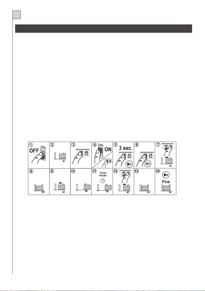
NL
PROGRAMMERING VAN DE WERK- EN PAUZETIJDEN
De besturingskast leert tijdens het programmeren de werk- en pauzetijden vanzelf (automatische teach-in).
Tijdens de programmeringfase wordt de P/P (trapsgewijze) besturing meerdere keren ingeschakeld (detail
1 van fig. 1). Als alternatief kan men de PP besturing (klem 8 van fig. 2, of de afstandsbediening (indien
gegevens opgeslagen zijn) gebruiken.
Er kunnen twee verschillende soorten installaties en methoden samengevat worden:
1) Installatie met eindschakelaars
Tijdens het programmeren wordt door het inschakelen van de eindschakelaars de grens van de beweging van de poort bepaald. Volg typologie 1 voor de programmering.
2) Installatie zonder elektrische eindaanslagen.
Tijdens de programmering bepaalt de ingreep van de obstakeldetector (indien aangebracht) de bewegingsgrens van het hek. Volg typologie 1 voor de programmering.
- Als er geen elektrische eindaanslagen voorhanden zijn en de antiverbrijzelingsbesturingskaart
erin gestoken is kunnen de tijden ook door middel van bediening van het bedieningselement van
de stappenfunctie (P/P knop) ingesteld worden. Volg typologie 2 voor de programmering.
Belangrijke opmerkingen alvorens tot de programmering over te gaan:
A.Schakel de stroom naar de besturingskast in en controleer aan de hand van de betreffende LED’s of de
besturingsingangen goed functioneren (de LED van de verbreekcontacten N.C. moet aan zijn).
B.Maak de bewegingszone van de poort vrij.
Programmering: Typologie 1
AUTOMATISERING MET ELEKTRISCHE EINDAANSLAGEN
1) Schakel de stroomvoorziening van de besturingskast uit.
2) Zet het hek of de deur half open.
3) Druk op de toets STOP/PROG.
4,5,6) Voorzie de regeleenheid van stroom door de toets STOP/PROG. minstens gedurende 3 sec. ingedrukt te houden
(detail 2 van fig. 1). Het programmeringled L1 gaat branden. (Dezelfde functie kan worden verkregen door de toets
STOP/PROG in te drukken, waardoor de resetpinnen heel even kortsluiten, en de toets STOP/PROG ingedrukt te houden tot led L1 gaat branden).
7) Druk op de P/P knop (detail 1 van fig. 1). De motor begint een sluitingsmanoeuvre. Indien de motor verkeerd draait,
dient men de stroomvoorziening weg te nemen, de fasen van de motor en de eindaanslag te verwisselen en de procedure te herhalen.
8,9) Bij de eindaanslag aangekomen, stopt de motor en begint de openingsprocedure automatisch.
10) Bij voltooide opening stopt de motor.
11) De regeleenheid begint de pauzetijd te tellen.
12) Druk op de P/P knop zodra de gewenste pauzetijd voorbij is en de motor begint de sluitingsprocedure.
13) Bij de eindaanslag voor de sluiting aangekomen, stopt de motor.
14) Einde van de programmering, led L1 gaat uit.
48
Page 49

NL
Programmering: Typologie 1
AUTOMATISERING MET ELEKTRISCHE EINDAANSLAGEN
1) Schakel de stroomvoorziening van de besturingskast uit.
2) Zet het hek of de deur half open.
3) Druk op de toets STOP/PROG.
4,5,6) Voorzie de regeleenheid van stroom door de toets STOP/PROG. minstens gedurende 3 sec. ingedrukt te houden (detail 2 van fig.
1). Het programmeringled L1 gaat branden. (Dezelfde functie kan worden verkregen door de toets STOP/PROG in te drukken, waardoor de resetpinnen heel even kortsluiten, en de toets STOP/PROG ingedrukt te houden tot led L1 gaat branden).
7) Druk op de P/P knop (detail 1 van fig. 1). De motor begint een sluitingsmanoeuvre. Indien de motor verkeerd draait, dient men de stroomvoorziening weg te nemen, de fasen van de motor en de eindaanslag te verwisselen en de procedure te herhalen.
8,9) Druk bij de stopaanslag aangekomen op de P/P knop. De motor stopt en de openingsprocedure begint automatisch.
10) Druk op de P/P knop zodra de deur volledig geopend is.
11) De regeleenheid begint de pauzetijd te tellen.
12) Druk op de P/P knop zodra de gewenste pauzetijd voorbij is en de motor begint de sluitingsprocedure.
13) Druk bij de stopaanslag aangekomen op de P/P knop en de motor stopt.
14) Einde van de programmering, led L1 gaat uit.
PROGRAMMERING VAN DE INGEBOUWDE ONTVANGER
De ingebouwde ontvanger leert de codes van de serie TANGO vanzelf (automatische teach-in). (TANGO
SW voor regeleenheid K100 SW)
Om de zenders in het geheugen op te slaan moet u als volgt handelen:
- Schakel de stroomvoorziening naar de besturingskast in.
- Controleer of de dipschakelaar functies nr. 10 op de stand ON staat.
- Druk even op de drukknop Stop/Prog. (det. 2 fig. 1) op de besturingskast waarna de LED L1 begint te
knipperen.
- Zend, binnen 5 seconden, met de te programmeren afstandsbediening.
- Als de led L1 langer knippert dan wil dat zeggen dat de opslag in het geheugen succesvol is geweest.
- Als de code reeds in het geheugen staat dan gaat de led L1 kort knipperen.
- Het is mogelijk om het geheugen van de codes te resetten door de knop STOP/PROG ongeveer 10 seconden lang ingedrukt te houden totdat L1 gaat branden.
- Indien de ingebouwde ontvanger niet gebruikt wordt dan MOET hij uitgeschakeld worden door de dipschakelaar 10 op de stand OFF te zetten.
INSTELLING VAN DE FUNCTIES (tabel 2)
De diverse opties die hiernaast beschreven worden kunnen ingesteld worden met de dipschakelaar functies (det. 4 fig. 1).
- Er wordt op gewezen dat om een verandering van de instellingen aan de besturingskast uit te voeren de stroomvoorziening even uit- en weer ingeschakeld moet worden of dat de 2 resetpinnen
van de besturingskast even kortgesloten moeten worden.
De trimmer PW (det. 5 fig. 1) regelt het vermogen van de motor (door hem met de klok mee te draaien
49
Page 50

NL
neemt het vermogen toe). Als het vermogen te laag ingesteld wordt kan het gebeuren dat de obstakeldetector inschakelt. MAS100 (indien ingeschakeld)
- De PW regeling wordt niet in aanmerking genomen bij elk begin van een beweging, waarbij gedurende enkele seconden vol vermogen wordt gegeven (aanloopfase) en tijdens de Soft-stop.
OBSTAKELDETECTOR
Deze controleert wanneer de motor mechanisch geblokkeerd wordt en laat als gevolg daarvan (gedurende
een paar seconden) een beweging tegengesteld aan de looprichting uitvoeren. Het inschakelen ervan wordt
aangegeven doordat de led L1 enkele keren knippert. De volgende (handbediende) beweging na het inschakelen ervan is tegengesteld aan die vóór de blokkering uitgevoerd werd, bijvoorbeeld als de motor tijdens
het openen geblokkeerd wordt, wordt er automatisch een korte sluitbeweging uitgevoerd en door op de
Start/Stop-drukknop in te drukken wordt het sluiten weer gestart.
- De obstakeldetector is uitgeschakeld tijdens de vertragingsfase.
TRIAC TEST
Door een storing aan dit onderdeel kan de werking en de veiligheid van de installatie in gevaar gebracht
worden. Daarom is er vóór elke beweging een controle opgenomen.
Als er een storing is wordt de besturingskast geblokkeerd en knippert het controlelampje poort open een
paar keer langzaam.
SOFT START
Met de soft start functie wordt het begin van de beweging geleidelijk uitgevoerd waardoor er schokbewegingen van de poort vermeden worden. Deze functie kan in ieder geval uitgeschakeld worden door Jp1 (det.
6 fig. 1) te overbruggen.
Let op: door Jp1 te overbruggen is de kracht van de motor altijd maximaal.
PARALLELE AANSLUITING VAN 2 MOTOREN
Indien er 2 motoren aangesloten moeten worden (bijvoorbeeld bij installaties voor het openen van kanteldeuren), moeten de 2 motoren en de 2 condensatoren parallel rechtstreeks op de aansluitklemmen van de
K100 aangesloten worden.
VERTRAGING
Bij enkele modellen kan het startpunt van de vertragingsfase geregeld worden door de trimmer TR (detail 19 van fig. 1).
Als er bij een installatie, waarbij de soft-stop toegepast wordt, tijdens de overgang van de normale snelheid
op langzaam, schokkende bewegingen aan de poort optreden, dan kan de wijze van de overgang als volgt
veranderd worden:
A - Schakel de stroomvoorziening uit.
B - Druk gelijktijdig op de Start/Stop-drukknop en de STOP-drukknop op de besturingskast (det. 1 en 2 fig. 1)
C - Schakel de stroomvoorziening weer in.
D - De led L1 (det. 10 fig. 1) geeft een korte signalering om aan te geven dat de overgang plaatsgevonden heeft.
Om naar de oorspronkelijke configuratie terug te gaan moet u de hierboven genoemde sequentie eenvoudigweg herhalen.
EINDTEST
Voer nadat de diverse programmeringen uitgevoerd zijn altijd een eindtest uit.
- Controleer of de beveiligingssystemen (obstakeldetector, noodstop, fotocellen, vaste druklijsten enz.)
goed functioneren.
- Controleer of de signaleringssystemen (knipperlichten, controlelampje poort open enz.) goed functioneren.
- Controleer of de besturingssystemen (Start/Stop-drukknop, afstandsbediening enz.) goed functioneren.
50
Page 51

NL
BELANGRIJKE AANWIJZINGEN TOT BESLUIT
- De installatie van de automatisering moet volgens de “regels van goed vakmanschap” uitgevoerd
worden door personeel dat aan de wettelijke eisen voldoet waarbij de normen EN 12453 en EN
12445 in acht genomen moeten worden.
- De installatie moet uitgerust worden met mechanische stops ook als er elektrische eindschkelaars voorhanden zijn.
- Als de soft-stop toegepast wordt, wordt de obstakeldetector tijdens deze fase uitgeschakeld.
Daarom moet de installatie met beveiligingssystemen zoals bijvoorbeeld vaste druklijsten uitgerust worden.
- Indien de motor met de hand gedeblokkeerd wordt moet vóórdat er een beweging verricht wordt
eerst de besturingskast gereset worden (de stroomvoorziening uit- en weer inschakelen).
Als dit niet mogelijk is synchroniseert de besturingskast zijn eigen bewegingen na 3 bewegingen.
- Verstrek de eindgebruiker alle informatie om de automatisering op de juiste manier te kunnen
gebruiken en stel hem op de hoogte van de mogelijke risico’s die hiermee samenhangen.
- Bewaar deze gebruiksaanwijzing zodat naderhand raadplegen altijd mogelijk is.
De firma TELCOMA S.r.l. behoudt zich het onaanvechtbare recht voor om op elk gewenst moment
de veranderingen aan te brengen die zij noodzakelijk acht om het product qua uiterlijk en/of qua
werking te verbeteren
VERWIJDERING
Dit product bestaat uit diverse onderdelen die ook weer verontreinigende stoffen kunnen bevatten.
Het product mag niet zomaar weggegooid worden!
Informeer over de wijze van hergebruik of verwijdering van het product en neem daarbij de wettelijke
voorschriften die ter plaatse gelden in acht.
EG-Verklaring van overeenstemming
volgens de Richtlijn 1999/5/EG (R&TTE)
Ondergetekende, , Enig Directeur van de firma:Augusto Silvio Brunello
TELCOMA S.r.l.Via L. Manzoni, 11 - Z.I. Campidui - 31015 Conegliano - (TV) Italy
verklaart dat het product:
Type: Besturingskast Model: K100 Toepassing: Besturingskast voor poortopeners
in overeenstemming is met de fundamentele eisen van artikel 3 en de betreffende bepalingen van de Richtlijn 1999/5/EG,
als het gebruikt wordt voor de doeleinden waarvoor het bestemd is
in overeenstemming is met de veiligheids- en gezondheidseisen, artikel 3.1.a
Toegepaste normen: EN 60950
in overeenstemming is met de eisen met betrekking tot de elektromagnetische compatibiliteit, artikel 3.1.b
Toegepaste normen: EN 301 489-3
in overeenstemming is met de eisen met betrekking tot de efficiëntie van de radiofrequentieimmissie in het spectrum, artikel 3.2
Toegepaste normen: ETSI EN 300 220-3
Plaats en datum: Conegliano, 12/01/05
De Enig Directeur
Augusto Silvio Brunello
51
Page 52

Telcoma srl - Via L. Manzoni, 11 - Z.I. Campidui - 31015 Conegliano - (TV) Italy
Tel. +39 0438-451099 - Fax +39 0438-451102 - Part. IVA 00809520265
http://www.telcoma.it E-mail: info@telcoma .it
 Loading...