

Page 1
CLASSIC PLUS
ATTUATORE OLEODINAMICO PER ANTE BATTENTI
I
MANUALE ISTRUZIONI
IL PRESENTE LIBRETTO È DESTINATO AL PERSONALE TECNICO QUALIFICATO ALLE INSTALLAZIONI
ACTIONNEUR OLÉODYNAMIQUE POUR PORTAILS À BATTANT
NOTICE D’INSTRUCTION
F
CETTE NOTICE S’ADRESSE À DES TECHNICIENS SPÉCIALISÉS DANS L’INSTALLATION
ACCIONADOR OLEODINÁMICO PARA POSTIGOS
E
MANUAL INSTRUCCIONES
EL PRESENTE FOLLETO ESTÁ DESTINADO AL PERSONAL TÉCNICO ESPECIALIZADO EN INSTALACIONES
ISTCLASSICPLUS
V. 09.2008
GB
D
NL
HYDRAULIC ACTUATOR FOR HINGED GATES
INSTRUCTION HANDBOOK
THIS HANDBOOK IS INTENDED FOR QUALIFIED TECHNICAL INSTALLERS
ÖLDYNAMISCHER AKTUATOR FÜR FLÜGELTORE
BEDIENUNGSANWEISUNGEN
DAS VORLIEGENDE HANDBUCH IST FÜR DAS MIT DER INSTALLATION BETRAUTE TECHNISCH QUALIFIZIERTE FACHPERSONAL BESTIMMT
HYDRAULISCHE ACTUATOR VOOR VLEUGELPOORTEN
GEBRUIKERSHANDLEIDING
DEZE HANDLEIDING IS BESTEMD VOOR VAKBEKWAME INSTALLATEURS
Telcoma srl - Via L. Manzoni, 11 - Z.I. Campidui - 31015 Conegliano - (TV) Italy
Tel. +39 0438-451099 - Fax +39 0438-451102 - Part. IVA 00809520265
http://www.telcoma.it E-mail: info@telcoma .it
Page 2
I
F
E
MODELLI E CARATTERISTICHE
CLASSIC PLUS: Gruppo martinetto con
centralina oleodinamica reversibile (CLASSIC
PLUS / R PLUS) o irreversibile (CLASSIC / I
PLUS), con sblocco manuale. Alimentazione
monofase 230Vac.
I CLASSIC / I-R 120° PLUS sono predisposti per
ottenere un angolo di apertura fino a 94° senza
bisogno d i messa in fase. Avendo
opportunamente saldato la bussola all’anta del
cancello, è possibile ottenere una rotazione
dell’anta finoa 116°.
I CLASSIC PLUS / I-R 180° garantiscono
aperturefino a 180°.
MODELES ET CARACTERISTIQUES
CLASSIC PLUS: Groupe vérin avec centrale
oléodynamique réversible (CLASSIC PLUS/R
PLUS) ou irréversible (CLASSIC/I PLUS), à
déverrouillagemanuel. Alimentation
monophasée 230 Vac.
Les CLASSIC/I-R 120° PLUS sont conçus
pour obtenir un angle d’ouverture pouvant
atteindre 94° sans qu’une mise en phase ne
soit nécessaire. Il est possible, après une
soudure appropriée de la douille au vantail du
portail, d’obtenir une rotation de ce dernier
d’un maximum de 116°.
Les CLASSIC PLUS/I-R 180° garantissent
une ouverture d’un maximum de 180°.
I
F
DATI TECNICI DONNÉES TECHNIQUES
MODELOS Y CARACTERÍSTICAS
CLASSIC PLUS: Grupo martinete con
centralita oleodinámica reversible (CLASSIC
PLUS/R PLUS) o irreversible CLASSIC/I
PLUS), con desbloqueo manual.
Alimentación monofásica 230 Vac.
I CLASSIC/I-R 120° PLUS están
predispuestos para obtener un ángulo de
apertura hasta 94° sin necesidad de puesta
en fase. Si se ha soldado adecuadamente el
buje al postigo de la verja, es posible obtener
una rotación del postigo hasta 116°.
I CLASSIC/I-R 180° PLUS garantizan una
apertura hasta 180°.
E
DATOS TÉCNICOS
U.M.
CLASSIC PLUS
Tensione di alimentazione
Corrente assorbita
Potenza assorbita
Condensatore
Coppia nominale
Temperatura di funzionamento
Intermittenza lavoro
Olio motore
Intervento termoprotezione
Grado di protezione
Peso
I
GUIDA ALL’INSTALLAZIONE
Lunghezza max anta
Peso max anta
Elettroserratura
Movimento
Uso
Tension d’alimentation
Courant absorbé
Puissance absorbée
Condensateur
Couple nominal
Température de fonctionnement
Intermittence de fonctionnement
Huile moteur
Intervention de thermoprotection
Degré de protection
Poids
F
Tensión de alimentación
Corriente absorbida
Potencia absorbida
Condensador
Par nominal
Temperatura de funcionamiento
Intermitencia trabajo
Aceite motor
Intervención termoprotección
Grado de protección
Peso
E
GUIDE À L’INSTALLATION GUÍA PARA LA INSTALACIÒN
Longueur max. du vantail
Poids max. du vantail
Serrure électrique
Mouvement
Usage
Longitud máxima postigo
Peso máx postigo
Electrocerradura
Movimiento
Uso
U.M.
m
Kg
V
A
W
µF
Nm
°C
%
-
°C
IP
Kg
CLASSIC PLUS/ I
2
400
(A)
(1)
(3)
230
1,2
280
8
400
-20 +70
70
TS 30
150
67
14
CLASSIC PLUS/ R
3
400
(B)
(2)
(3)
A) No A) Non A) No
B) Si B) Oui B) Si
1) Irreversibile 1) Irréversible 1) Irreversible
2) Reversibile 2) Réversible 2) Reversible
3) Residenziale/comunità 3) résidentiel/collectivité 3) vivienda/comunidad
2
Page 3
GB
D
NL
MODELS AND CHARACTERISTICS
CLASSIC PLUS:
(CLASSIC PLUS/R PLUS) or irreversible
(CLASSIC PLUS/I) hydraulic control unit, with
manual release.
Single-phase power supply 230 Vac.
The CLASSIC/I-R 120° PLUS are designed to
obtain an opening angle up to 94° without the
necessity for regulation. By suitably welding the
bush to the gate, rotation up to 116° may be
obtained.
The CLASSIC.I-R 180° PLUS guarantee
opening up to 180°.
Jack assembly with reversible
MODELLE UND KENNDATEN MODELLEN EN SPECIFICATIES
CLASSI C PLUS:
umkehrbarerö ldynami schen Zent rale
( C L A S SI C P LU S / R P L U S ) o d er
selbsthemmend (CLASSIC PLUS/I), mit
manueller Entriegelung.
Einphasige Versorgung 230 Vac.
Die CLASSIC/I-R 120° PLUS sind vorbereitet,
um einen Öffnungswinkel von 94° zu erzielen,
ohne die Notwendigkeit der Phasenstellung.
Nachdem die Buchse an dem Torflügel auf
geeignete Weise angeschweißt ist, ist es
möglich, eine Drehung des Torflügels bis zu
116° zu erzielen.
Die CLASSIC/I-R 180° PLUS garantieren
Wi n d e ne i n he i t mit
CLASSIC PLUS:
hydraulische besturingskast zonder blokkering
(omkeerbaar) (CLASSIC PLUS/R PLUS) of met
blokkering (onomkeerbaar) (CLASSIC PLUS/ I)
met handmatige ontgrendeling.
Éénfasevoeding 230 Vac.
De CLASSIC / I en R 120 PLUS zijn ingesteld
om een openingshoek tot 94° te verkrijgen
zonder dat afstelling nodig is. Na de bus naar
behoren aan de poortvleugel gelast te hebben is
het mogelijk een vleugeldraaiing tot 116° te
verkrijgen.
De CLASSIC / I en R 180 PLUS garanderen een
opening tot 180°.
Öffnungen bis zu 180°.
GB
D
NL
TECHNICAL DATA TECHNISCHE DATEN TECHNISCHE GEGEVENS
Cilindereenheid met
U.M.
CLASSIC PLUS
Supply voltage
Current consumption
Input power
Capacitor
Nominal torque
Operating temperature
Working intermittence
Motor oil
Thermal cut-out
Protection rating
Weight
GB
Versorgungsspannung
Stromaufnahme
Leistungsaufnahme
Kondensator
Nenndrehmoment
Betriebstemperatur
Arbeitsintermittenz
Motoröl
Überhitzungsschutz
Schutzgrad
Gewicht
D
Voedingsspanning
Stroomverbruik
Vermogensverbruik
Condensator
Nominaal koppel
Bedrijfstemperatuur
Intermitterend bedrijf
Motorolie
Inschakeling thermische beveiliging
Beschermingsgraad
Gewicht
NL
INSTALLATION GUIDE INSTALLATIONSANWEISUNGEN LEIDRAAD VOOR DE
INSTALLATIE
Max. single gate length
Max. single gate weight
Electric lock
Movement
Use
Max. Länge des Torflügels
Höchstgewicht des Torflügels
Elektroschloß
Bewegung
Anwendung
Max. lengte vleugel
Max. gewicht vleugel
Elektrische vergrendeling
Beweging
Gebruik
U.M.
m
Kg
V
A
W
µF
Nm
°C
%
-
°C
IP
Kg
230
1,2
280
8
400
-20 +70
70
TS 30
150
67
14
CLASSIC PLUS/ I CLASSIC PLUS/ R
2
400
(A)
(1)
(3)
3
400
(B)
(2)
(3)
A) No A) Nein A) Nee
B) Yes B) Ja B) Ja
1) Irreversible 1) selbsthemmend 1) Met blokkering (onomkeerbaar)
2) Reversible 2) umkehrbar 2) omkeerbaar
3) dwelling/community 2) Wohnhaus/Apartmentgebäude 2) woningen/woonblokken
3
Page 4
I F E
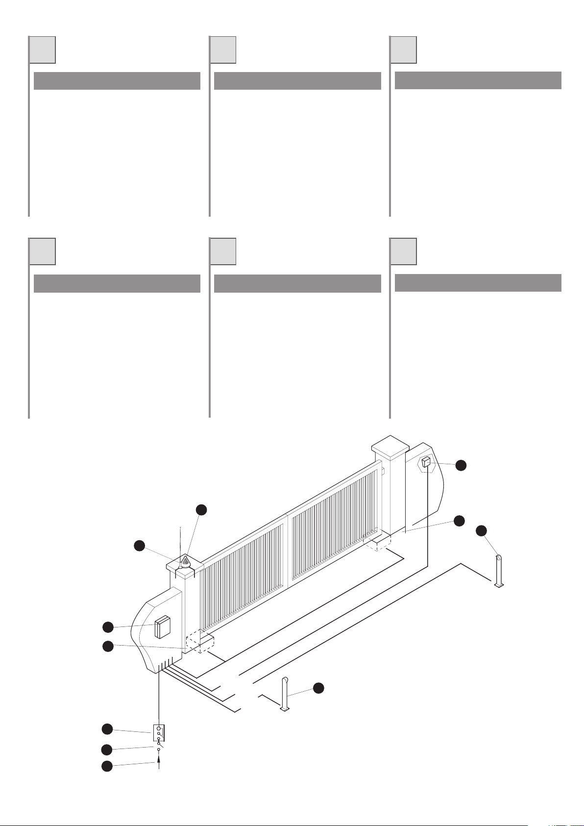
QUADRO D’INSIEME
1. Linea di alimentazione
2. Interruttore generale
3. Interruttore differenziale
4. CLASSIC
5. Box con centralina
6. Antenna
7. Lampeggiatore
8. Selettore a chiave
9. Fotocellule
TABLEAU D’ENSEMBLE
1. Ligne d’alimentation
2. Interrupteur général
3. Interrupteur différentiel
4. CLASSIC
5. Armoire avec centrale
6. Antenne
7. Clignotant
8. Sélecteur à clé
9. Cellules photoélectriques
CUADRO DEL CONJUNTO
1. Línea de alimentación
2. Interruptor general
3. Interruptor diferencial
4. CLASSIC
5. Caja con centralita
6. Antena
7. Luz centelleante
8. Selector a llave
9. Fotocélulas
GB D NL
GENERAL LAYOUT GESAMTÜBERSICHT TOTAALBEELD
1. Power supply line
2. On/off switch
3. Differential safety switch
4. CLASSIC
5. Control unit box
6. Antenna
7. Flashing light
8. Key selector switch
9. Photocells
1. Zufuhrleitung
2. Hauptschalter
3. Trennschalter
4. CLASSIC
5. Box mit Zentrale
6. Antenne
7. Blinklicht
8. Schlüsselschalter
9. Fotozellen
1. Voedingsleiding
2. Hoofdschakelaar
2. Aardlekschakelaar
4. CLASSIC
5. Kast met besturingseenheid
6. Antenne
7. Knipperlicht
8. Sleutelschakelaar
9. Fotocellen
8
7
4
9
6
2x1
RG58
5
4
3x0.5
0.5
2x
.5
0
x
4
230V
3x1.5
3
5
x2.
2
/
5
.
1
x
4
9
2
1
4
Page 5
I
F
E
VERIFICHE PRELIMINARI
Prima di passare all’installazione assicurarsi
che:
1. La struttura del cancello sia solida ed appropriata
2. Le cerniere di supporto dell’anta non presentino segni di cedimento e/o irregolarità
3. Il movimento dell’anta durante tutta la corsa sia senza punti di attrito o vibrazioni
4. La corsa dell’anta sia limitata in apertura
ed in chiusura, da arresti in gomma saldamente fissati al suolo.
CONTROLES PRELIMINAIRES
Il est conseillé, avant de passer à la pose, de
s’assurer des points suivants:
1. La structure du portail doit être solide et
adéquate.
2. Les charnières de support du vantail sont
solides et/ou ne présente nt pas
d’irrégularités.
3. Le mouvement du vantail se produit sur
toute sa course sans points de frottement
ni vibrations.
4. La course du vantail est limitée en ouverture comme en fermeture par des arrêts
en caoutchouc solidement fixés au sol.
CONTROLES PRELIMINARES
Antes de pasar a la fase de in stalación
asegurarse que:
1. La estructura de la verja sea sólida y
adecuada
2. Las bisagras de soporte del postigo no
presenten señales de cedimiento y /o
irregularidades
3. El movimiento del postigo durante todo su
recorr ido sea sin ro zamiento s ni
vibraciones
4. El recorrido del postigo sea limitado en
cierre y en apertura por topes revestidos
en goma, fijados al piso sólidamente.
GB
PRELIMINARY CHECKS
Prior to installation, check that:
1. the structure of the gate is suitable and
sturdy;
2. the gate supporting hinges show no signs
of weakness and/or irregularity
3. the gate moves without any friction or
vibration;
4. the opening and closing movement of the
gate is limited by rubber stops firmly fixed
to the ground.
D
VORBEREITENDE
ÜBERPRÜFUNGEN
Vor der Durchführung der Installation ist
sicherzustellen, daß:
1. die Struktur des Tors solide und geeignet
ist.
2. die Stützscharniere des Torflügels keine
Zeichen von Absenkungen und/oder
Unregelmäßigkeiten aufweisen.
3. die Bewegung des Torflügels über den
gesamten Verlauf ohne Reibungspunkte
oder Vibrationen ist.
4. der Lauf des Torflügels sowohl bei der
Öffnung als auch bei der Schließung durch
ein Paar Stopper aus Gummi limitiert ist,
die am Boden fest befestigt sind.
NL
CONTROLES VOORAF
Het is verstandig om vóór de installatie de
volgende controles te verrichten.
1. Het frame van de poort moet stevig en
geschikt zijn.
2. De steunscharnieren van de poortvleugel
mogen geen tekenen van bezwijking en/of
afwijkingen vertonen.
3. Gedure nde de hele cyclus dient de
beweging van de vleugel vloeiend en
zonder wrijving of trillingen te zijn.
4. De slag van de poortvleugel moet zowel
tijdens het openen als tijdens het sluiten
begrensd worden door rubbere n
aanslagen, die stevig aan de gro nd
vastgemaakt moeten worden.
5
Page 6
I
F E
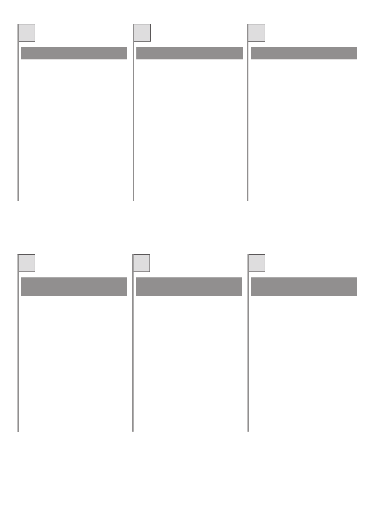
INSTALLAZIONE
Dopo che la cassa di fondazione per l’alloggio
del gruppo è stata sistemata procedere come
segue:
1.Togliere il coperchio della cassa di
fondazione;
2.Prima di inserire il gruppo pompa, alimentare
lo stesso portando l'albero scanalato fino in
battuta,facendo attenzione di effettuare tutta
la corsa di rallentamento, ruotando in senso
antiorario per installazioni SX ed in senso
orario per installazioni DX (vedi Fig.a/Abb.a).
3.Collocare il gruppo pompa all'interno della
cassa di fondazione imboccando la bussola
inferiore alla bussola superiore
precedentemente fissata all'anta del
cancello;
4.IMPORTANTE: Assicurarsi che
l'accoppiamento albero scanalatobussola inferiore sia adeguatamente
ingrassato
5.Fissare il martinetto alla cassa di fondazione,
sbloccare la centralina idraulica (vedi
“FUNZIONAMENTO MANUALE”) e verificare
che l'anta, azionata manualmente, apra e
chiuda correttamente; dopodiché assicurare il
fissaggio del martinetto alla cassa di
fondazione con le quattro viti in dotazione,
serrandole con tenacia.
In figura 1 è rappresentata un tipo di
installazione destra. Con installazione destra si
intende attuatore montato a destra della luce di
passaggio (visto dall’interno). Per una
installazione sinistra ruotare di 180° la
centralina idraulica.
INSTALLATION
Après avoir installé la caisse de fondation
permettant de loger le groupe procéder de la
manière suivante:
1.Retirer le couvercle de la caisse de fondation
2.Avant d'introduire le groupe pompe,
l'alimenter en amenant l'arbre rainuré en
butée en faisant attention à effectuer toute la
course de ralentissement, en tournant dans
le sens inverse des aiguilles d'une montre
pour les installations gauches et dans le sens
des aiguilles d'une montre pour les
installations droites (voir Fig.a).
3.Placer le groupe pompe à l'intérieur de la
caisse de fondation en emboîtant la douille
inférieure à la douille supérieure fixée
précédemment au vantail du portail.
4.IMPORTANT: S'assurer que l'accou-
plement arbre rainuré-douille inférieure
est correctement graissé
5.Fixer le vérin à la caisse de fondation,
débloquer le groupe hydraulique (voir «
FONCTIONNEMENT MANUEL ») et vérifier
que le vantail, actionné manuellement,
s'ouvre et se ferme correctement ; ensuite
fixer le vérin à la caisse de fondation à l'aide
des quatre vis fournies en les serrant avec
force.
Un type d’installation à droite est présenté sur
la figure 1.
L’expression «installation à droite» indique que
l’actionneur est monté à la droite de l’ouverture
de passage (vu de l’intérieur)
Pour une installation à gauche, tourner de 180°
la centrale hydraulique.
INSTALACIÓN
Después que la caja de fundación, para el
alojamiento del grupo, ha sido colocada
proceder en el siguiente modo:
1.Quitar la tapa de la caja de fundación
2.Antes de activar el grupo bomba, aliméntelo
colocando el eje acanalado hasta el tope,
efectuando toda la carrera de desaceleración
y girando en el sentido antihorario para las
instalaciones a izquierda y en el sentido
horario para las instalaciones a derecha
(véase la Fig.a).
3.Coloque el grupo bomba en el interior de la
caja de cimentación, introduciendo el
casquillo inferior en el casquillo superior
fijado antes a la hoja de la cancela;
4.IMPORTANTE: controle que el acopla-
miento entre el eje acanalado y el
casquillo inferior esté bien engrasado
5.Fije el gato a la caja de cimentación,
desbloquee la central hidráulica (véase
“FUNCIONAMIENTO MANUAL”) y controle
que la hoja, accionada manualmente, se
abra y se cierre correctamente; luego
controle que el gato esté fijado a la caja de
cimentación con los cuatro tornillos
suministrados, apretándolos con una tenaza.
La figura 1 está representada con tipo de
instalación derecha.
Con instalación derecha se entiende activador
montado a la derecha de la luz de paso (visto
desde el interior)
Para una instalación a izquierda rotar de 180°
la centralita hidráulica .
Senso di apertura
Sens d'ouverture droit
Sentido de apertura derecho
Fig. 1 / Abb. 1
6
INSTALLAZIONE SINISTRA
INSTALLATION GAUCHE
INSTALACIÓN A IZQUIERDA
INSTALLAZIONE DESTRA
INSTALLATION DROITE
INSTALACIÓN A DERECHA
Fig. a / Abb. a
Page 7
GB
D NL
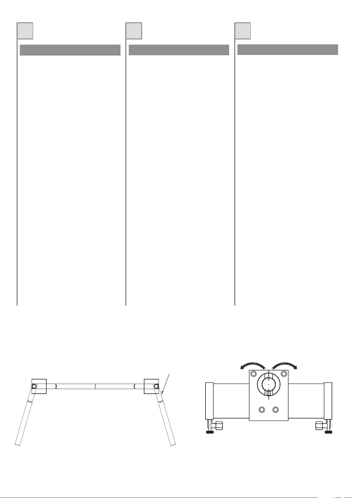
INSTALLATION
After having positioned the foundation box for
housing the unit, proceed as follows:
1.remove the cover of the foundation box;
2.Before fitting the pump unit, feed it by taking
the serrated shaft as far as the stop, making
sure that the deceleration phase is fully
completed, turning it anti-clockwise for LH
installations and clockwise for RH
installations (see Fig. a/Abb. a);
3.Introduce the pump unit into the foundation
box, fitting the lower bush to the upper bush
that has already been fixed to the leaf of the
gate;
4.IMPORTANT: make sure that the serrated
shaft-bush connection is adequately
greased
5.Fix the jack to the foundation box, release the
hydraulic control unit (see “MANUAL
OPERATION”) and check that the manually
operated leaf opens and closes correctly;
after which, secure the jack to the foundation
box with the four supplied screws making
sure they are fully tightened.
Figure 1 shows installation to the right.
Installation to the right means that the actuator
is mounted to the right of the gateway (seen
from inside).
For installation to the left, turn the hydraulic
control unit 180°.
INSTALLATION
Nachdem der Fundamentskasten für die
Aufnahme der Einheit untergebracht wurde, ist
wie folgt zu verfahren:
1.Den Deckel von dem Fundamentskasten
entfernen.
2.Bevor das Pumpenaggregat eingeschaltet
wird, muss dieses gespeist werden. Hierzu
die Keilwelle durch Drehen gegen den
Uhrzeigersinn für Installationen LINKS und
im Uhrzeigersinn für Installationen RECHTS
(siehe Abb. a) bis zum Anschlag verschieben
und den ganzen Verlangsamungslauf
ausführen.
3.Das Pumpenaggregat im Fundamentkasten
unterbringen und die untere Büchse mit der
vorher am Torflügel befestigten oberen
Büchse verbinden.
4.WICHTIG: Sicher stellen, dass die
Verbindung zwischen Keilwelle und
unterer Büchse entsprechend eingefettet
ist.
5.Den Zylinder am Fundamentkasten
befestigen, die Hydraulikzentrale einschalten
(siehe “MANUELLER BETRIEB”) und prüfen,
dass sich das von Hand betätigte Tor korrekt
öffnet und schließt. Danach den Zylinder mit
den vier mitgelieferten Schrauben am
Fundamentkasten verankern und fest
anziehen.
In der Abbildung 1 ist die Art der Installation auf
der rechten Seite dargestellt.
Unter Installation auf der rechten Seite versteht
sich, daß der Aktuator rechts vom Durchgang
montiert wird (vom Inneren aus gesehen).
Für eine linke Installation die hydraulische
Zentrale um 180° drehen.
INSTALLATIE
Nadat de funderingskast voor de montage van
de unit geplaatst is moet u het volgende doen:
1.Haal de kap van de funderingskast af.
2.Alvorens de pompgroep aan te brengen dient
u die te voeden waarbij u de gegroefde as tot
de aanslag brengt en let erop de hele
vertragingsloop uit te voeren waarbij u tegen
de wijzers van de klok in draait voor
installaties links en met de wijzers van de
klok mee voor installaties rechts (zie afb. a).
3.Plaats de pompgroep in de funderingskast
waarbij u de onderste bus op de bovenste
bus aansluit welke u daarvoor op de
poortvleugel hebt bevestigd;
4.BELANGRIJK: Vergewis u ervan dat de
koppeling gegroefde as met de onderste
bus adequaat ingevet is
5.Bevestig de bedieningscilinder aan de
funderingskast, ontgrendel de hydraulische
besturingseenheid (zie
“HANDMATIGE WERKING”) en controleer of
de vleugel wanneer die handmatig in
beweging wordt gebracht, correct open en
dicht gaat; vergewis u er daarna van dat de
besturingscilinder stevig vast op de
funderingskast zit door die met de vier
meegeleverde schroeven helemaal vast te
draaien.
Op figuur 1 is een installatievoorbeeld aan de
rechterkant afgebeeld.
Met installatie aan de rechterkant wordt
bedoeld dat de actuator aan de rechterkant van
de doorgangsopening is gemonteerd
(vanbinnen uit gezien).
Voor installatie aan de linkerkant moet de
hydraulische besturingseenheid 180°
gedraaid.
Fig. 1 / Abb. 1
Right-hand opening
Öffnungssinn rechts
Openingsrichting rechts
LEFT-HAND INSTALLATION
INSTALLATION LINKS
INSTALLATIE LINKS
RIGHT-HAND INSTALLATION
INSTALLATION RECHTS
INSTALLATIE RECHTS
Fig. a / Abb. a
7
Page 8
I F E
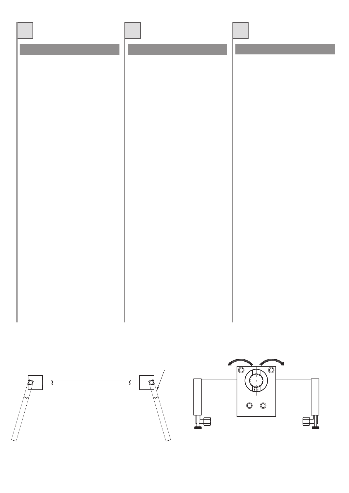
1. Vite di fissaggio
2. Valvola di spurgo
3. Chiave di sblocco
4. Staffe di supporto
5. Vite M4x6
6. Spia dell’olio
7. Centralina idraulica
8. Martinetto idraulico
1. Vis de fixation
2. Soupape de purge
3. Clé de déverrouillage
4. Etriers de support
5. Vis M4x6
6. Témoin huile
7. Centrale hydraulique
8. Vérin hydraulique
1. Tornillos de fijación
2. Válvula de evacuación
3. Llave de desbloqueo
4. Grapas de soporte
5. Tornillo M4x6
6. Indicador aceite
7. Centralita eléctrica
8. Martinete hidráulico
GB D NL
1. Clamping screw
2. Bleed valve
3. Release key
4. Supporting brackets
5. Screw M4x6
6. Oil level indicator
7. Hydraulic control unit
8. Hydraulic jack
1. Befestigungsschrauben
2. Ablaßventil
3. Entriegelungsschlüssel
4. Stützbügel
5. Schraube M4x6
6. Ölstandsanzeiger
7. Hydraulikzentrale
8. Hydraulikwinde
1. Bevestigingsschroef
2. Ontluchtingsventiel
3. Ontgrendelsleutel
4. Steunbeugels
5. Schroef M4x6
6. Oliekijkglas
7. Hydraulische besturingseenheid
8. Hydraulische cilinder
8
Page 9
I
F
E
COLLEGAMENTI ELETTRICI
Collegare i fili AP/CH e COMUNE (BLU o
GRIGIO) del cavo motore alla morsettiera
della centralina elettronica.
Il condensatore deve essere collegato in
parallelo ai morsetti AP/CH della centralina
elettronica.
Per una eventuale inversione del senso di
marcia invertire i fili AP/CH sulla morsettiera
della centralina elettronica.
N.B.
La eventuale limitazione di coppia nella
centralina elettronica di comando va regolata
al massimo in modo da escluderla
completamente. In caso contrario il gruppo
idraulico può andare in blocco.
RACCORDEMENTS
ELECTRIQUES
Relier les fils AP/CH (Ouvert/Fermé) et le
COMMUN (Bleu ou gris) du câble moteur au
serrecâble de la centrale électronique.
Le condensateur doit être raccordé en
parallèle aux bornes AP/CH de la centrale
électronique.
Pour inverser éventuellement le sens de
fonctionnement inverser les fils AP/CH sur le
serre-câble de la centrale électronique.
N.B.
L’éventuelle limitation de couple dans la
centrale électronique de commande doit être
réglée au maximum de manière à l’exclure
complètement. Dans le cas contraire un
blocage du groupe hydraulique peut se
produire.
CONEXIONES ELECTRICAS
Conectar los cables AP/CH y COMUN (Azul o
gris) del cable motor a la bornera de la
centralitaelectrónica.
El condensador debe estar conectado en
paralelo a los bornes AP/CH de la centralita
electrónica.
Para una eventual inversión del sentido de
marcha invertir los cables AP/CH en la
bornera de la centralita electrónica.
NOTA.
La eventual limitación de par en la centralita
electrónica de mando debe ser regulada al
máximo en manera de excluirla
completamente. En caso contrario el grupo
hidráulico puede bloquearse.
GB
ELECTRICAL CONNECTIONS
Connect the AP/CH and COMMON (Blue or
grey) wires of the motor cable to the electronic
control unit terminal board.
The capacitor should be connected in parallel
to terminals AP/CH of the electronic control
unit.
To reverse the directionof movement, invert
the AP/CH wires on the electronic control unit
terminal board.
N.B.
Any limitation of torque in the electronic control
box should be regulated on maximum in order
to cut it out completely, otherwise the hydraulic
unit may jam.
D
ELEKTROANSCHLUSS
Die Drähte AP/CH und GEMEIN (Blau oder
grau) des Motorkabels an der Klemmenleiste
der elektronischen Zentrale anschließen. Der
Kondensator muß parallel zu den Klemmen
AP/CH der elektronischen Zentrale
angeschlossen werden. Für eine eventuelle
Umkehr der Laufrichtung die Drähte AP/CH
auf der Klemmenleiste der elektronischen
Zentrale umkehren.
Hinweis:
Die eventuelle Drehmomentbegrenzung auf
der elektronischen Steuerzentrale wird auf
Maximum eingestellt, um diese vollständig
auszuschließen. Andernfalls kann sich die
Hydraulikeinheit blockieren.
NL
ELEKTRISCHE AANSLUITINGEN
Sluit de draden AP/CH en de NULLEIDIN
(Blauw of grijs) G van de motorkabel aan op
de klemmenstrook van de elektronische
besturingskast. De condensator moet
parallelgeschakeld worden met de klemmen
AP/CH van de elektronische
besturingskast.Om de looprichting eventueel
om te keren moeten de draden AP/CH op de
klemmenstrook van de
elektronischebesturingskast verwisseld
worden.
N.B.:
De eventuele koppelbegrenzing van de
elektronische besturingskast moet op het
maximum ingesteld worden zodat deze
volledig uitgeschakeld is. Als dit niet het geval
is kan de hydraulische eenheid geblokkeerd
worden.
9
Page 10
I
F E
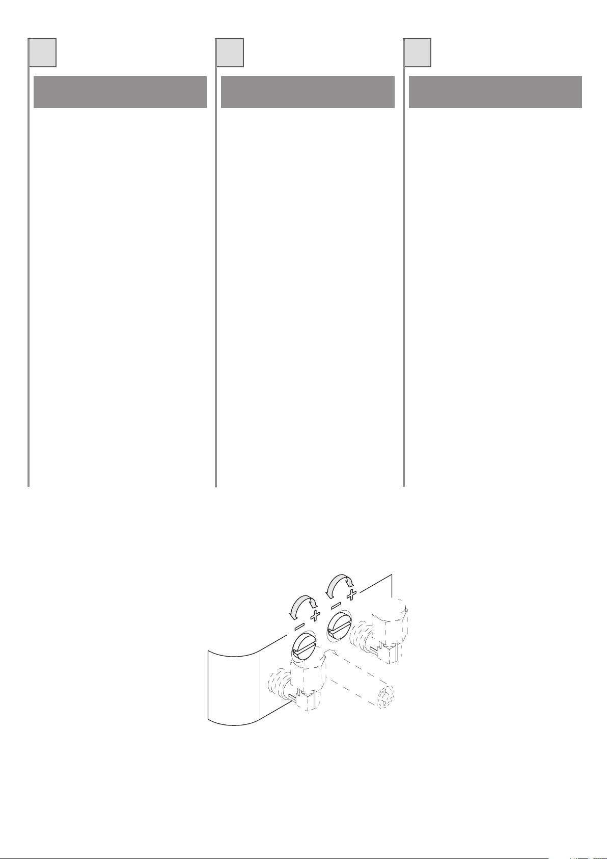
REGOLAZIONE DELLA FORZA
TRASMESSA
La forza trasmessa dalla centralina idraulica
al cancello viene regolata da una coppia di
valvole by-pass (fig. 2) una di colore argento e
l’altra di colore giallo. Una valvola serve per
regolare la forza in chiusura, e l’altra per regolare la forza in apertura.
La forza aumenta ruotando le valvole in senso
orario e diminuisce ruotandole in senso
antiorario.
Si consiglia di iniziare con le valvole svitate
quasi del tutto e proseguire per tentativi, tenendo presente che con minime rotazioni si
ottengono ogni volta variazioni significative.
N.B.
Le valvole regolano la forza trasmessa e
non la velocità di movimento del cancello.
REGLAGE DE LA FORCE
TRANSMISE
La force transmise par la centrale hydraulique
au portail est réglée par deux valves by-pass
(fig. 2), une de couleur argent et l’autre de
couleur jaune. Une valve sert pour régler la
force en fermeture et l’autre pour régler celle
en ouverture..
La force transmise augmente en faisant tourner
les valves dans le sens des aiguilles d’une
montre et diminue en les faisant tourner dans
le sens contraire.
Il est conseillé de commencer le réglage avec
les valves prati quement dévissées puis
d’effectuer des tentatives successives sans
jamais oublier que des rotations minimes
peuvent parfois produire des variati ons
importantes.
N.B.
Les valves règlent la force transmise et non
la vitesse d’évolution du portail.
REGULACION DE LA FUERZA
TRANSMITIDA
La fuerza transmitida por la centralita hidráulica
a la verja está regulada por una par de válvulas
by-pass (ver fig. 2), una de color plata y la otra
amarilla. Una válvula sirve para regular la
fuerza en fase de cierre y la otra para regular
la fuerza en fase de apertura.
La fuerza aumenta rotando las válvulas en
sentido de las agujas del reloj y disminuye
girándolas en sentido contrario.
Se aconseja iniciar con las válvulas casi totalmente destornilladas y actuando por tentativos,
teniendo presente que con rotaciones mínimas
se obtienen cada vez variaciones significativas.
Nota
Las válvulas regulan la fuerza transmitida
y no la velocidad de movimiento de la
verja.
10
Fig. 2 / Abb. 2
Page 11

GB
D NL
ADJUSTING THE TRANSMITTED
FORCE
The force transmitted by the hydraulic control
unit to the gate is regulated by a pair of bypass valves (fig. 2), one coloured silver and
the other yellow. One valve serves to regulate
the closing force and the other the opening
force.
The force increases upon turning the valves
clockwise and decreases when turning them
counter-clockwise.
It is advisable to start with the valves almost
totally loosened and proceed by trial and error,
taking into account that a minimum rotation
causes a significant variation.
N.B.
The valves regulate the transmitted
force and not the gate speed.
REGULIERUNG DER
ÜBERTRAGUNGSKRAFT
Die Übertragungskraft der Hydraulikzentrale
auf das Tor wird durch ein Paar Bypass-Ventile
reguliert (Abb. 2), eins silberfarbig und das
andere in gelber Farbe. Ein Ventil dient zur
Regulierung der Kraft bei der Schließung und
das andere für die Regulierung der Kraft bei
der Öffnung.
Die Kraft erhöht sich, wenn die Ventile im
Uhrzeigersinn gedreht werden und verringert
sich, indem sie gegen den Uhrzeigersinn
gedreht werden.
Es ist ratsam, mit den praktisch vollständig
ausgedrehten Ventilen zu beginnen und durch
Versuche vorzugehen, wobei daran erinnert
wird, daß mit minimalen Drehungen jedes Mal
bedeutende Veränderungen erzielt werden.
Hinweis:
Die Ventile regeln die Übertragungskraft
und nicht die Bewegungsgeschwindigkeit
des Tors.
KRACHTREGELING
De kra cht die door de hydraulische
besturingseenheid naar de poort overgebracht
wordt, wordt geregeld door een set (2) by-pass
ventielen (fig. 2), waarvan er één zilverkleurig
is en het andere geel van kleur is. Het ene
ventiel dient om de kracht tijdens het sluiten te
regelen en het andere om de kracht tijdens het
openen te regelen.
Door de ventielen met de wijzers van de klok
mee te draaien (naar rechts) neemt de kracht
toe en door de ventielen tegen de wijzers van
de klok in te draaien (naar links) neemt de
kracht af.
Er wordt geadviseerd om met de ventielen bijna
volledig losgedraaid te beginnen en het daarna
steeds een beetje te proberen, waarbij u er
rekening mee moet houden dat telkens als u
een klein beetje aan de ventielen draait dit
aanzienlijke veranderingen tot gevolg heeft.
N.B.:
De ventielen regelen de overgebrachte
kracht en niet de bewegingssnelheid van
de poort.
Fig. 2 / Abb. 2
11
Page 12

I
F E
REGOLAZIONE DELLA FRENATA
Per la regolazione della frenata del martinetto
in apertura ed in chiusura agire sulle due manopole (part. 1 fig.3).
GB
ADJUSTING BRAKING
Use the two knobs (part 1 fig. 3) to adjust
braking of the jack during opening and closing.
RECLAGE DU FREINAGE
Pour le réglage du freinage du vérin en ouverture et en fermeture, agir sur les deux poignées
(détail 1 fig. 3).
REGULACION DEL FRENADO
Para la regulación del frenado del martinete
en apert ura y cierre actuar sobre las dos
manoplas (detalle fig. 3).
D NL
BREMSREGULIERUNG
Für die Regulierung der Bremsung der Winde
bei der Öffnung und der Schließung sind die
beiden Drehknöpfe zu betätigen (Detail 1, Abb.
3).
REGELING VAN DE REMKRACHT
Om de remkracht van de cilinder tijdens het
openen en het sluiten te regelen moet u aan
de beide knoppen (detail 1, fig. 3) draaien.
12
2
1
Fig. 3 / Abb. 3
Page 13

I
F E
FUNZIONAMENTO MANUALE
In situazioni di emergenza (temporanea mancanza di di alimentazione di rete, anomalia di
funzionamento, etc) l’apertura o la chiusura del
cancello puo’ avvenire manualmente.
Lo sbloccaggio dei CLASSIC / I consiste nell’estrarre il tappo, inserire l’apposita chiave facendola poi ruotare in senso antiorario di un
paio di giri ed agire manualmente sul cancello
(fig. 4). Per ribloccare agire inversamente.
Lo sbloccaggio dei CLASSIC / R consiste nello sbloccare l’elettroserratura con l’apposita
chiave ed agire manualmente sul cancello.
GB
MANUAL OPERATION
In an emergency (te mpora ry blackout,
malfunctioning, etc.), the gate may be opened
and closed manually.
To release the CLASSIC/I, remove the cap,
insert the relative key, turn it counter-clockwise
for two full turns and manually move the gate
(fig. 4). To re-lock, proceed as above in the
reverse order.
To release the CLASSIC/R, release the electric
lock using the relative key and manually move
the gate.
FONCTIONNEMENT MANUEL
Il est possible, en situation d’urgence (coupure
momentanée de courant, mauvais fonctionnement, etc.) d’effectuer manuellement l’ouverture ou la fermeture du portail.
Pour débloquer les CLASSIC/I introduire la clé
prévue à cet effet après avoir retiré le bouchon
puis la tourner deux fois dans le sens contraire
des aiguilles d’une montre avant de pousser
le portail à la main (fig. 4). Pour bloquer de
nouveau répéter les opérations dans le sens
contraire.
Pour débloquer les CLASSIC/R, déverrouiller
la serrure électrique à l’aide de la clé prévue à
cet effet puis pousser le portail à la main.
FUNCIONAMIENTO MANUAL
En situaciones de emergencia (temporánea
falta de alimentación a la red, anomalía de
funcionamiento, etc.) la apertura o cierre de la
verja puede ser efectuada manualmente.
El desbloqueo de los CLASSIC/I consiste en
extraer la tapa, introducir la adecuada llave
girándola un par de veces en sentido contrario a las agujas del reloj, y luego accionar manualmente sobre la verja (fig. 4). Para volver a
bloquear se debe operar en modo inverso.
El desbloqueo de los CLASSIC/R consiste en
desbloquear la electro cerra dura con la
adecuada llave, siendo posible luego accionar
manualmente la verja
D NL
MANUELLER BETRIEB
In Notsituation (vorübergehender Ausfall der
Netzversorgung, Betriebsstörungen, usw.)
kann die Öffnung bzw. Schließung des Tors
manuell erfolgen.
Die Entriegelung der CLASSIC/I besteht darin,
den Stopfen herauszuziehen, den
entsprechenden Schlüssel einzusetzen und
diesen anschließend gegen den Uhrzeigersinn
einige Male umzudrehen und das Tor manuell
zu betä tigen (A bb. 4). Für die
Wiederverriegelung umgekehrt vorgehen.
Die Entriegelung der CLASSIC/R besteht
dari n, das Elektro schloß mit dem
entsprechenden Schlüssel zu entriegeln und
das Tor manuell zu betätigen.
HANDMATIGE BEDIENING
In noodgevallen (tijdelijke stroomuitval en
storingen in de werking etc.) kan de poort
handmatig geopend en gesloten worden.
Om de CLASSIC / I te ontgrendelen moet u de
dop verwijderen, de speciale sleutel erin doen
en de sleutel daarna een paar slagen tegen
de wijzers van de klok in draaien (naar links)
en de poort met de hand bewegen (fig. 4). Om
de poort weer te vergrendelen moet u het
omgekeerde doen.
Om de CLASSIC / R te ontgrendelen moet de
elektrische vergrendeling met de speciale
sleutel ontgrendeld worden en moet de poort
met de hand bewogen worden.
MA
N
A
U
.
T
.
Fig. 4 / Abb. 4
13
Page 14

I
F E
ELETTROSERRATURA
Nelle figg. 5 e 6 sono raffigurati due esempi di
installazione fra i più comuni. Si raccomanda
di rispettare tassativamente le quote riportate
in dette figg., in quanto le dilatazioni termiche
potrebberro provocare delle variazioni dimensionali tali da causare difficoltà nell’innesto e/
o disinnesto dello scrocco.
GB
SERRURE ELECTROMECANIQUE
Deux exemples d’installation parmi les plus
communs sont représentés sur les figures 5 et
6. Il est reco mmandé de respecter
formellement les cotes reportées sur ces
figures dans la mesure où des dilatations
thermiques pourraient provoquer des variations
de dimensions risquant gêner l’enclenchement
et/ou le déclenchement du déclic.
ELECTROCERRADURA
En las fig. 5 y 6 están representados dos
ejemplos, entre los más comunes, de
instalación. Se aconseja respeta r
taxativamente las cotas indicadas en dichas
figuras, puesto que las dilataciones térmicas
podrían ocasionar variaciones dimensionales
tales de crear dificultades en el acoplamiento
o desacoplamiento del picaporte.
D NL
ELECTRIC LOCK
Figures 5 and 6 show two of the most common
examples of installation. The values given in
these figures must be observed since thermal
expansion could cause varia tio ns in the
dimensions which would make engagement
and/or release of the spring-lock difficult.
ELEKTROSCHLOSS
In den Abbildungen 5 und 6 sind zwei Beispiele
für die häufigsten Installationen dargestellt. Es
ist rats am, die in diesen Abbildungen
angegebenen Quote n unbedingt zu
respektieren, da Wärmeausdehnungen
Veränderungen der Abmessungen hervorrufen
könnten, die wiederum Schwierigkeiten bei der
Koppelung und/oder Loslösung der Klinke
verursachen könnten.
ELEKTRISCHE VERGRENDELING
Op fig. 5 en 6 zijn de meest gangbare
installatievoorbeelden afgebeeld. Er wordt
geadviseerd de maten die op genoemde
figuren staan vermeld uiterst nauwkeurig aan
te houden omdat door uitzetting door warmte
de afmetingen zodanig kunnen veranderen dat
het koppelen en/of het ontkoppelen van de veer
moeilijker gaat.
5 mm
Fig. 5 / Abb. 5
14
5 mm
Fig. 6 / Abb. 6
Page 15
I
F E
SPURGO DEL MARTINETTO
Ogni volta si renda necessaria la sostituzione
o il rabbocco dell’olio eseguire l’operazione di
spurgo. Agire come segue:
1. Impostare sulla centralina elettronica il tempo massimo di lavoro, in modo che la pompa continui il suo funzionamento anche
dopo che l’anta sia andata in battuta d’arresto.
2. Azionare la centralina elettronica di comando.
3. Spurgare l’aria aprendo una delle due valvole fino a che esca solo olio (part. 2 fig. 3)
4. Chiudere la valvola e ripeterne l’operazione con l’altra.
GB
PURGE DU VERIN
L’opération de purge doit être effectuée à
chaque remise à niveau ou remplacement de
l’huile. Agir de la manière suivante:
1. Programmer sur la centrale électronique
une durée de fonctionnement maximum de
façon à ce que la pompe contin ue à
fonctionner après même l’arrêt du vantail
contre la butée.
2. Actionner la centrale électronique de
commande.
3. Purger l’air, en ouvrant une des deux
soupapes, jusqu’à ce que de l’huile ne sorte
(détail 2 fig. 3).
4. Fermer la première soupape et répéter
l’opération avec l’autre.
EVACUACIÓN DEL MARTINETE
Cada vez que resulte necesaria la sustitución
o adición del aceite efectuar la operación de
evacuación.
Actuar en la siguiente manera:
1. Plantear en la centralita electrónica el
2. Accionar la centralita electrónica de man-
3. Evacuar el aire abri endo una de las
4. Cerrar la válvula y repetir la operación con
D NL
tiempo máximo de trabajo, en modo tal que
la bomba siga funcionando ta mbién
después que el postigo se haya parado.
do
válvulas hasta que salga solo aceite
(detalle 2 en la fig. 3)
la otra.
BLEEDING THE JACK
Whenever the oil needs changing or topping
up, bleed the jack as follows:
1. Set maximum working ti me on th e
electronic control unit so that the pump
continues to operate even after the gate
has reached the stop.
2. Activate the electronic control unit.
3. Bleed by opening one of the two valves until
just oil comes out (part 2 fig. 3).
4. Close the valve and repeat the operation
with the other.
ENTLÜFTUNG DER WINDE
Jedes Mal, wenn der Austausch oder die
Nachfü llung mit Öl notw endig ist, die
Entlüftungsoperation durchführen, wobei wie
folgt zu verfahren ist:
1. Auf der elektro nischen Zentra le die
maximale Betriebszeit einstellen, so daß
die Pumpe ihren Betrieb fortsetzt, auch
nachdem die Stange am Endanschlag in
Kontakt gekommen ist.
2. Die elektronische Steuerzentrale betätigen.
3. Die Luft durch Öffnen einer der beiden
Ventile ablassen bis nur noch Öl austritt
(Detail 2, Abb. 3).
4. Das Ventil schließen und die Operation bei
dem anderen Ventil wiederholen.
DE CILINDER ONTLUCHTEN
Telkens als de olie ververst of bijgevuld moet
worden moet de cilinder ontlucht worden.
Ga als volgt te werk:
1. Stel de elektronische besturingskast in op
de maximum looptijd zodat de pomp blijft
functioneren ook als de poortvleugel tegen
de aanslag aan is gekomen.
2. Stel de elektronische besturingskast in
werking.
3. Laat de lucht ontsnappen door één van de
beide ventielen open te doen totdat er
alleen olie uitstroomt (detail 2, fig. 3).
4. Doe het ventie l dicht en doe daarna
hetzelfde bij het andere ventiel.
15
Page 16

I
F
E
SOSTITUZIONE OLIO
La sostituzione dell’olio deve essere eseguita
dopo 6/7000 cicli ( 1 ciclo = apertura+chiusura)
o ogni 2 anni circa agendo nel seguente modo:
1. Staccare il quadro di alimentazione generale dell’impianto.
2. Estrarre la centralina idraulica e svitare la
spia dell’olio
3. Usando un contenitore svuotare l’olio dalla
centralina idraulica
4. Sbloccare la centralina idraulica
5. Fare eseguire un ciclo completo di apertura e chiusura manualmente e ripetere il
punto 3
6. Riempire la centralina idraulica d’olio
7. Eseguire un ciclo di apertura e chiusura
in modo che l’olio arrivi fino al martinetto
idraulico.
8. Eseguire lo spurgo del martinetto.
9. Rabboccare la centralina idraulica e avvitare la spia dell’olio.
10. Risistemare la centralina come in origine
11. Dare alimentazione
REMPLACEMENT DE L’HUILE
L’huile doit être remplacée après 6/7000 cycles
(1 cycle = ouverture + fermeture), ou tous les
deux ans environ, de la manière suivante:
1. Débrancher le tableau d’alimentation
générale de l’installation.
2. Extraire la centrale hydraulique et dévisser
le voyant de l’huile.
3. Utiliser un récipient pour vider l’huile de
la centrale hydraulique.
4. Débloquer la centrale hydraulique.
5. Effectuer manuellement un cycle complet
d’ouverture et de fermeture et répéter le
point 3.
6. Remplir la centrale hydraulique d’huile.
7. Effectuer un cycle d’o uvertu re et de
fermeture de façon à ce que l’huile arrive
jusqu’au vérin hydraulique.
8. Purger le vérin.
9. Rétablir le niveau d’huile de la centrale
hydraulique et revisser le témoin de l’huile.
10. Replacer la centrale comme elle l’était
initialement.
11. Alimenter de nouveau en courant.
SOSTITUCIÓN DEL ACEITE
La sustitución del aceite debe ser efectuada
después de 6 / 7.000 ciclos (1 ciclo = apertura
+ cierre) o cada dos años, actuando en la
siguiente manera:
1. Desconectar el cuadro de alimentación
general de la instalación.
2. Extraer la centralita hidráulica y destornillar
el indicador del aceite
3. Usando un recipiente, vaciar el aceite de
la centralita hidráulica
4. Desbloquear la centralita hidráulica
5. Efectuar un ciclo completo de apertura y
cierre manualmente y repetir el punto 3
6. Llenar la centralita hidráulica de aceite
7. Efectuar un ciclo completo de apertura y
cierre en modo tal que el aceite llegue al
martinete hidráulico
8. Efectuar la evacuación del martinete
9. Llenar la centralita hidráulica y atornillar el
indicador del aceite.
10. Montar la centralita.
11. Activar la alimentación
L’olio esausto sostituito deve essere raccolto secondo le disposizioni di legge e
consegnato agli enti preposti per la raccolta.
L’huile usée remplacée doit être recueillie
selon les dispositions de loi et remise aux
services chargés de l’éliminer.
El aceite usado sustitu ido debe ser
recogido según la disposiciones legales
o entregado a las entidades autorizadas
para la recolección.
16
Page 17

GB
D
NL
OIL CHANGE
The oil should be changed after 6/7000 cycles
(1 cycle = opening+closing) or approx. once
every 2 years. Proceed as follows:
1. Disconnect the entire installation from the
power supply.
2. Remove the hydraulic control unit and
unscrew the oil level indicator.
3. Empty out the oil from the hydraulic control
unit into a container.
4. Release the hydraulic control unit.
5. Manually open and close the gate once
and then repeat point 3.
6. Fill the hydraulic control unit with oil.
7. Carry out one opening and closing cycle
so that the oil reaches the hydraulic jack.
8. Bleed the jack.
9. Top up the hydraulic control unit and screw
on the oil level indicator.
10. Replace the control unit in its correct
position.
11. Connect to the power supply.
The used oil should be collected according
to the law and delivered to authorised
bodies for its disposal.
ÖLWECHSEL
Der Ölwechsel muß alle 6/7000 Zyklen
durchgeführt werden (1 Zyklus = Öffnung +
Schließung) bzw. ungefähr alle 2 Jahre, wobei
wie folgt zu verfahren ist:
1. Die Hauptversorgungstafel von der Anlage
trennen.
2. Die Hydraulikzentrale herausnehmen und
den Ölstandanzeiger ausschrauben.
3. Unter Verwendung eines Behälters das Öl
aus der Hydraulikzentrale ablassen.
4. Die Hydraulikzentrale entriegeln.
5. Einen kompletten Zyklus der Öffnung und
Schließung manuell durchführen und den
Punkt 3 wiederholen.
6. Die Hydraulikzentrale mit Öl auffüllen.
7. Einen Zyklus der Öffnung und Schließung
durchfü hren, so daß das Öl bis zur
Hydraulikwinde reicht.
8. Die Entlüftung der Winde vornehmen.
9. Die Hydraulikzentrale auffüllen und den
Ölstandanzeiger festschrauben.
10. Die Zentra le in den ursprünglichen
Zustand zurückbringen.
11. Die Stromversorgung wieder herstellen.
Das ausgetauschte Altö l muß
entsprechend den gesetzlic hen
Bestimmungen aufgefangen und den für
die Entsorgung zuständigen Behörden
übergeben werden.
OLIE VERVERSEN
De olie moet na 6/7000 cycli (1 cyclus =
openen+sluiten) of circa om de 2 jaar ververst
worden waarbij u het volgende moet doen:
1. Schakel de hoofdvoedingskast van de
installatie uit.
2. Haal de hydraulische besturingseenheid
eruit en draai het oliekijkglas los.
3. Neem een bak en laat de olie uit de
hydraulische besturingseenheid lopen.
4. Ontg rendel de hydraulische
besturingseenheid.
5. Voer met de hand een volledige openingsen sluitingscyclus uit en herhaal de in punt
3 beschreven handeling.
6. Vul de hydraulische besturingseenheid
met olie.
7. Voer een openings- en sluitingscyclus uit
zodat de olie naar de hydraulische cilinder
stroomt.
8. Ontlucht de cilinder.
9. Vul de hydraulische besturingseenheid
met olie bij en draai het oliekijkglas vast.
10. Doe de besturingseenheid weer op de
oorspronkelijke plaats.
11. Schakel de netvoeding weer in.
De afgewerkte verv erste olie moet in
overeenste mming met de wette li jk e
voorschriften opgevangen worden en bij
de specia al daarvoor beste mde
inzamelinstanties ingeleverd worden.
17
Page 18

I
F E
ANOMALIE E RIMEDI
1. Il cancello non apre. I motori funzionano, ma non avviene il movimento in
apertura.
a) Verificare che il gruppo non sia in Funzionamento Manuale (sbloccato).
b) Verificare che non vi siano difetti di assetto meccanico del cancello (per esempio, sfregamento delle parti terminali delle
ante o interferenza tra le ante e la battuta
al suolo).
c) Assicurarsi che la regolazione di coppia
sulla centralina elettronica di comando sia
esclusa.
d) Nel caso dei “reversibili” controllare il corretto funzionamento dell’elettroserratura.
e) Se il martinetto esegue la manovra inversa (chiusura invece di apertura e viceversa) invertire i fili APRE/CHIUDE sulla
morsettiera della centralina elettronica.
2. Il cancello non apre o non chiude. Il motore elettrico non funziona e non si avverte, quindi, alcun rumore o vibrazione.
a) Verificare che l’apparecchiatura elettronica sia regolarmente alimentata.
b) Verificare l’efficienza dei fusibili
c) Verificare l’efficienza dei condensatori
di avviamento motore. Per controllare questa condizione collegare un condensatore
volante da 8µF in parallelo ai fili marrone e
nero della centralina idraulica.
d) Verificare con l’ausilio di adeguati strumenti diagnostici che le funzioni dell’apparecchiatura elettronica siano corrette.
e) Accertarsi che il motore riceva alimentazione.
f) Verificare che la regolazione delle valvole by-pass non sia eccessiva, in quanto,
stringendole troppo si può bloccare il funzionamento del motore.
3. Il martinetto procede a scatti e quindi
il movimento del cancello risulta irregolare.
a) Controllare il livello dell’olio nel serbatoio e nel caso sia scarso, provvedere al
rabbocco.
b) Potrebbe essere entrata aria nell’impianto. In questo caso occorre intervenire spurgando il martinetto.
ANOMALIES ET REMEDES
1. Le portail n’ouvre pas. Les moteurs
fonctionnent mais le mouvement d’ouverture n’a pas lieu.
a) Contrôler que le groupe ne soit pas en
Fonctionnement Manuel (déverrouillé).
b) Contrôler que l’assiette mécanique du
portail ne présente pas de défauts (par
exemple qu’il n’y ait pas de frottements
entre les extrémités des vantaux ou entre
les vantaux et la butée au sol).
c) S’assurer que le réglage de couple sur
la centrale électronique de commande soit
exclu.
d) Dans le cas d’un foncti onnement
réversible contrôler le bon fonctionnement
de la serrure électromécanique .
e) Si le vérin effectue la manoeuvre inverse (fermeture au lieu d’ouverture et viceversa) invertir les fils OUVRE/FERME sur
le serre-câble de la centrale électronique.
2. Le portail n’ouvre pas et ne ferme pas.
Le moteur électrique ne fonctionne
pas; on ne remarque donc aucun bruit
ni vibration.
a) Contrôler l’alimentation de l’appareillage
électronique.
b) Contrôler les fusibles.
c) Contr ôler les condensateurs de
démarrage du moteur. Pour ce faire, relier
un condensateur libre de 8µF en parallèle
aux fils marron et noir de la centrale
hydraulique.
d) Vérifier à l’aide d’instruments de
diagnostic appropriés que les fonctions de
l’appareillage électronique soient correctes.
e) S’assurer que le moteur soit alimenté.
f) Contrôler que les valves by-pass ne
soient pas trop serrées car elles pourraient
bloquer le fonctionnement du moteur.
3. Le vérin fonctionne par saccades et le
mouvement du porta il est donc
irrégulier.
a) Contrôler le niveau d’huile dans le
réservoir et en rajouter éventuellement.
b) De l’air a pu rentrer dans l’installation. Il
est alors nécessaire de purger le vérin.
ANOMALÍAS Y SOLUCIONES
1. La verja no se abre. Los motores
funcio nan pero no se verific a el
movimiento de apertura.
a) Verif icar que el gru po no esté en
Funcionamiento Manual (desbloqueado).
b) Verificar que no existan defectos en la
disposición mecánica de la verja (por
ejemplo, roce de las partes terminales de
los postig os o interferencia entre los
postigos y el apoyo al suelo).
c) Asegurarse que la regulación de par
en la centralita electrónica de mando esté
excluida.
d) En caso de los reversibles controlar el
corre cto fu ncionamiento de la
electrocerradura.
e) Si el martinete efectúa la maniobra inversa (cierre en vez de apertura) invertir
los cables ABRE/CIERRA en la bornera
de la centralita electrónica.
2. La verja no abre o cierra. El motor
eléctrico no funciona y no se advierte
ningún rumor o vibración.
a) Verificar que los instr umento s
eléctr icos esté n adecuadamente
alimentados
b) Verificar la eficiencia de los fusibles
c) Veri ficar la efi ciencia de los
condensadores de arranque del motor.
Para controlar esta condición conectar un
condensador volante de 8µF en paralelo a
los cables marrón y negro la centralita
hidráulica.
d) Verificar, con la ayuda de adecuados
instrumentos diagnósti cos, que las
funciones de los instrumentos eléctricos
sean correctas.
e) Asegurars e que el moto r re ciba
alimentación
f) verificar que la regulación de la válvula
by-pass no sea excesiva, ya que
ajustándola demasiado se puede llegar al
bloqueo del motor.
3. El martinete procede a saltos y por lo
tanto el movimiento de la verja es
irregular.
a) Controlar el nivel del aceite en el
depósito y en caso sea escaso, añadir.
b) Podría haber entrado agua en la
instalación, en este caso se debe actuar
evacuando el martinete.
18
Page 19

GB
D
NL
MALFUNCTIONING. REMEDIES
1. The gate does not open. The motors
work, but th ere is no openin g
movement.
a) Check that the unit is not in the manual
mode of operation (released).
b) Check that the gate has no mechanical
defects (e.g. rubbing between gate meeting stiles or interference between gate and
stop in the ground).
c) Make sure that the torque regulation on
the electronic control unit is cut out.
d) With the reversible models, check that
the electric lock is in proper working order.
e) If the jack carrie s out the reverse
movement (closing instead of opening and
vice versa), invert the OPEN/CLOSE wires
on the electronic control unit terminal
board.
2. The gate neither opens nor closes. The
electric motor does not work and there
is no noise or vibration.
a) Check that the electronic equipment is
powered.
b) Check the fuses.
c) Check the motor start-up capacitors.
To do this, connect a 8µF field capacitor in
parallel to the brown and black wires of the
hydraulic control unit.
d) With the help of suitable instruments,
check that the functions of the electronic
equipment are correct.
e) Make sure that the motor is powered.
f) Check that the by-pass valves have not
been over-tightened, as this could stop
motor operation.
3. The jack and consequently the gate
move jerkily.
a) Check the oil level in the tank and if
necessary top up.
b) Air could have entered the system, in
which case the jack should be bled.
BETRIEBSSTÖRUNGEN
UND DEREN BEHEBUNG.
1. Das Tor öffnet sich nicht. Die Motoren
funktionieren, aber es erfolgt keine
Öffnungsbewegung.
a) Überprüfen, daß die Einheit nicht in
manuellem Betrieb ist (entriegelt).
b) Überprüfen, daß keine Defekte der
mechanischen Trimmung des Tors
bestehen (z.B. Abrieb der Endteile der
Torflügel oder Interferenzen zwischen den
Torflügeln und dem Anschlag am Boden).
c) Sicherstellen, daß die Regulierung des
Drehmoments auf der elektronischen
Steuerzentrale ausgeschlossen ist.
d) Im Falle der umkehrbaren Tore ist der
einwandfreie Betrieb des Elektroschlosses
zu überprüfen.
e) Wenn die Winde das umgekehrte
Manöver durchführ t (Schließung statt
Öffn ung und vicevers a), die Drä hte
ÖFFNEN/S CHLIESSEN auf der
Klemmenleiste der elektronischen Zentrale
umkehren.
2. Das Tor öffnet und schließt nicht. Der
Elektromotor funktioniert nicht und es
ist somit kein erlei Geräusch oder
Vibration feststellbar.
a) Überp rü fen, daß die elektronis che
Apparatur regulär versorgt wird.
b) Die Leistungsfähigkeit der Sicherungen
überprüfen.
c) Die Leistungsfähigkeit der Kondensatoren des Motorstarts überprüfen. Um diese
Bedingung zu kontr ollieren, einen
Kondensator von 8 µF parallel zu dem
braunen und dem schwarzen Draht der
Hydraulikzentrale anschließen.
d) Mit Hilfe geeigneter Diagnoseinstrumente überprüfen, ob die Funktionen der
elektronischen Apparatur korrekt sind.
e) Sicherstellen, daß der Motor versorgt ist.
f) Überprüfen, daß die Einstellung der
Bypass-Ventile nicht übermäßig ist, da sich
der Motorbetrieb durch zu starkes
Anziehen blockieren könnte.
3. Die Winde arbeitet schrittweise und die
Bewegung des Tors erfolgt irregulär.
a) Den Ölstand im Tank kontrollieren, und
falls dieser zu niedrig ist, die Auffüllung
vornehmen.
b) Luft könnte in die Anlage eingetreten
sein. In diesem Fall ist es notwendig, die
Winde zu entlüften.
STORINGEN EN OPLOSSINGEN
1. De poort gaat niet open. De motoren
werken, maar tijdens het openen is er
geen beweging.
a) Ga na dat de unit niet op de
handbediende stand staat (ontgrendeld).
b) Ga na dat de poort geen mechanische
defecten vertoont (ga bijvoorbeeld na dat
de uiteinden van de poortvleugels niet
ergens tegen aan komen of dat de vleugels
de aanslag op de grond niet raken).
c) Ga na dat de krachtregeling op de
elektronische besturingskast uitgeschakeld
is.
d) Controleer bij de modellen zonder
blokkering (omkeerbaar) of de elektrische
vergrendeling goed functioneert.
e) Als de cilinder in de verkeerde richting
beweegt (sluiten in plaats van openen) dan
moeten de draden OPENEN/SLUITEN op
de klemmenstrook van de elektronische
besturingskast verwisseld worden.
2. De poort gaat niet open of dicht. De
elektromotor werkt niet en maakt geen
enkel geluid of trillingen.
a) Controleer of de voeding goed is
aangesloten op de elektr onische
besturingskast.
b) Controleer de zekeringen.
c) Controleer of de opstart-condensatoren
van de motor doeltreffend zijn. Om dit te
kunnen controleren moet u een losse
condensator van 8µF parallelgeschakeld
op de bruine en de zwarte draad van de
hydra ulische besturi ngseenheid
aansluiten.
d) Ga met de juiste controle-apparatuur na
of de elektronische apparatu ur goed
functioneert.
e) Controleer of de motor voeding krijgt.
f) Ga na dat de regeling van de by-pass
ventielen niet overdreven is omdat als de
ventielen te strak aangedraaid worden de
werking van de motor geblokkeerd kan
worden.
3. De cilinder werkt met horten en stoten en
als gevolg daarvan is de beweging van de
poort niet vloeiend.
a) Controleer het oliepeil in het reservoir
en vul de olie bij als er niet voldoende olie
in blijkt te zitten.
b) Er kan lucht in de installatie terecht zijn
gekomen. In dat geval moet u de cilinder
ontluchten.
19
Page 20

I F E
AVVERTENZE IMPORTANTI
SULL'INSTALLAZIONE
- L'installazione dell'automazione deve essere
eseguita a regola d'arte da personale qualificato
avente i requisiti di legge e fatta in conformità della
direttiva macchine 98/37/CE e alle normative
EN13241-1, EN 12453 e EN 12445.
- Verificare la solidità delle strutture esistenti
(colonne, cerniere, ante) in relazione alle forze
sviluppate dal motore.
- Verificare che vi siano dei fermi meccanici di
adeguata robustezza a fine apertura e fine
chiusura delle ante.
- Verificare lo stato di eventuali cavi già presenti
nell'impianto.
- Fare un'analisi dei rischi dell'automazione e di
conseguenza adottare le sicurezze e le
segnalazioni necessarie.
- Installare i comandi (ad esempio il selettore a
chiave) in modo che l'utilizzatore non si trovi in una
zona pericolosa.
- Terminata l'installazione provare più volte i
dispositivi di sicurezza, segnalazione e di sblocco
dell'automazione.
- Applicare sull'automazione l'etichetta o la
targhetta CE contenenti le informazioni di pericolo
e i dati di identificazione.
- Consegnare all'utilizzatore finale le istruzioni
d'uso, le avvertenze per la sicurezza e la
dichiarazione CE di conformità.
- Accertarsi che l'utilizzatore abbia compreso il
corretto funzionamento automatico, manuale e di
emergenza dell'automazione.
- Informare l'utilizzatore per iscritto (ad esempio
nelle istruzioni d'uso) :
* dell'eventuale presenza di rischi residui non
protetti e dell'uso improprio prevedibile.
* Di scollegare l'alimentazione quando viene
eseguita la pulizia nell'area dell'automazione o
viene fatta piccola manutenzione (es:
ridipingere).
* Di controllare frequentemente che non vi siano
danni visibili all'automazione e nel caso ve ne
siano, avvertire immediatamente l'installatore
* Di non far giocare i bambini nelle immediate
vicinanze dell'automazione
- Predisporre un piano di manutenz ion e
dell'impianto (almeno ogni 6 mesi per le sicurezze)
riportando su di un apposito registro gli interventi
eseguiti.
AVERTISSEMENTS IMPORTANTS
CONCERNANT L'INSTALLATION
L'installation de l'automation doit être effectuée
dans les règles de l'art par du personnel spécialisé,
conformément aux dispositions légales, à la
directive machine 98/37/CE et aux normes EN
12453 et EN 12445.
- S'assurer que les structures existantes (colonnes,
charnières, vantaux) soient suffisamment solides
pour résister aux forces développées par le moteur.
- S'assurer que les arrêts mécaniques en fin
d'ouverture et en fin de fermeture des vantaux
soient suffisamment robustes.
- Vérifier l'état des câbles qui se trouvent
éventuellement déjà dans l'installation
- Faire une analyse des risques de l'automation et
adopter, en fonction de celle-ci, les dispositifs de
sécurité et de signalisation nécessaires.
- Installer les commandes (par exemple le sélecteur
à clé) de manière à ce que l'utilisateur ne se trouve
pas dans une zone dangereuse.
- Une fois l'installation terminée, tester plusieurs fois
les dispositifs de sécurité, de signalisation et de
déverrouillage de l'automation.
- Appliquer sur l'automation l'étiquette ou la plaque
CE où sont indiqués les dangers présentés par
l'automation ainsi que les données d'identification
de la machine.
- Remettre à l'utilisateur final le mode d'emploi, les
avertissements concernant la sécurité et la
déclaration CE de conformité.
- S'assurer que l'utilisateur a bien compris le
fonctionnement automatique, manuel et d'urgence
de l'automation.
- Informer par écrit l'utilisateur (par exemple dans le
mode d'emploi) de l'éventuelle présence de risques
résiduels non couverts et des utilisations impropres
prévisibles.
- Informer l'utilisateur par écrit (par exemple dans le
mode d'emploi) :
* de la présence éventuelle de risques résiduels
non protégés et de l'usage impropre prévisible.
* De la nécessité de couper l'alimentation quand
le nettoyage de la zone de l'automatisme a lieu
ou en cas de petites interventions de
maintenance (ex. Repeindre).
* De la nécessité de contrôler fréquemment
l'absenc e de dommag es visibles à
l'automatisme et s'il y en a, avertir
immédiatement l'installateur.
* Qu'il ne faut pas laisser les enfants jouer à
proximité de l'automatisme.
- Etablir un plan de maintenance de l'installation (au
moins tous les 6 mois pour les dispositifs de
sécurité) en inscrivant sur un registre prévu à cet
effet les interventions effectuées.
ADVERTENCIAS IMPORTANTES
SOBRE LA INSTALACION
- La instalación del automatismo debe ser realizada
según los cánones, por personal cualificado que
reúna los requisitos establecidos por la ley y de
conformidad con la Directiva sobre máquinas
98/37/CE y con las normas EN 12453 y EN 12445.
- Compruebe la solidez de las estructuras
existentes (columnas, bisagras, hojas) en relación
con las fuerzas desarrolladas por el motor.
- Controle que haya retenes mecánicos de solidez
adecuada en los puntos de fin de apertura y de fin
de cierre de las hojas.
- Controle el estado de los cables ya existentes en la
instalación, en su caso.
- Haga un análisis de los riesgos del automatismo y
adopte los dispositivos de seguridad y las
señalizaciones necesarias en consecuencia.
- Instale los mandos (por ejemplo, el selector de
llave) de manera que el usuario no se encuentre en
una zona peligrosa.
- Terminada la instalación, pruebe varias veces los
dispositivos de seguridad, señalización y
desbloqueo del automatismo.
- Aplique en el automatismo una etiqueta o una
placa CE que contenga las informaciones de
peligro y los datos de identificación.
- Entregue al usuario final las instrucciones para el
uso, las advertencias para la seguridad y la
declaración CE de conformidad.
- Asegúrese de que el usuario haya comprendido el
correcto funcionamiento automático, manual y de
emergencia del automatismo.
- Informe al usuario por escrito (por ejemplo, en los
manuales de instrucciones) de la eventual
presencia de riesgos residuales no protegidos y del
uso inadecuado previsible.
- Informe al usuario por escrito (por ejemplo en las
instrucciones de uso) :
* sobre la presencia de riesgos residuales no
protegidos y sobre el uso inadecuado previsible.
* que debe desconectar la alimentación cuando
hace la limpieza en la zona de la automatización
o si hace un pequeño mantenimiento (ej.:
Pintar).
* que debe controlar a menudo que la
automatización no presente daños visibles y, en
el caso de que los haya, deberá advertir de
inmediato al instalador
* que no debe permitir que los niños jueguen en
las cercanías de la automatización
- Predisponga un programa de mantenimiento de la
instalación (al menos cada 6 meses para los
dispositivos de seguridad), anotando en un registro
expresamente dedicado las intervenciones
realizadas.
SMALTIMENTO ELIMINATION ELIMINACION
Questo prodotto è formato da vari componenti che
potrebbero a loro volta contenere sostanze
inquinanti. Non disperdere nell'ambiente!
Informarsi sul sistema di riciclaggio o smaltimento del
prodotto attenendosi alle norme di legge vigenti a
livello locale.
20
Ce produit est constitué de divers composants qui
pourraient à leur tour contenir des substances polluantes.
Ne pas laisser ce produit gagner l'environnement.
S'informer sur le système de recyclage ou
d'élimination du produit conformément aux
dispositions légales en vigueur à un niveau local.
Este producto está constituido por varios
componentes que podrían, a su vez, contener
sustancias contaminantes. ¡No los vierta en el medio
ambiente!
Infórmese sobre el sistema de reciclaje o eliminación
del producto con arreglo a las leyes vigentes en
ámbito local.
Page 21
GB D NL
IMPORTANT RECOMMENDATIONS
CONCERNING INSTALLATION
- Only qualified personnel having the legal
requirements must install the automation according
to the principles of good workmanship and in
conformity with the machinery directive 98/37/CE
and standards EN 12453 and EN 12445.
- Check that the existing structures (posts, hinges,
leaves) are stable in relation to the forces developed
by the motor.
- Check that suitably robust limit stops have been
installed for end of gate opening and closing.
- Check the state of the cables that are already
present in the system.
- Analyse the hazards connected with the automation
system and adopt the necessary safety and
signalling devices accordingly.
- Install the commands (e.g. the key selector) so that
the user is not placed in a hazardous area when
using them.
- Upon completion of the installation, test the safety,
signalling and release devices of the automation
system several times.
- Apply the CE label or plate with information
regarding the hazards and identification data on the
automation.
- Give the end user the instructions for use, the safety
recommendations and the CE declaration of
conformity.
- Ensure that the user has understood the correct
automatic, manual and emergency operation of the
automation system.
- Inform the user in writing (e.g. in the instructions for
use) of any unprotected residual risks and of
foreseeable misuse.
- Inform the user in writing (in the use instructions for
example):
* Of possible non secluded residual risks and of
foreseeable improper use.
* To disconnect the power supply when cleaning
the area that is automated or when performing
small maintenance operations (e.g.: Repainting).
* To frequently control that no visible damage has
occurred to the automation, and to inform the
installer immediately if damage is noticed.
* Not to allow children to play in the vicinity of the
automation.
- Prepare a maintenance schedule for the
automation installation (at least once every 6
months for the safety devices), recording the work
carried out in a special book.
WICHTIGE
INSTALLATIONSHINWEISE
- Die Installation der Automatisierung muss in
Übereinstimmung mit der Maschinenrichtlinie 98/37/EU
und den Bestimmungen EN 12453 und EN 12445,
fachgerecht und von qualifiziertem Personal, das die
gesetzlichen Anforderungen erfüllt, vorgenommen
werden.
- Die Stabilität der vorhandenen Strukturen (Säulen,
Scharniere, Flügel) im Hinblick auf die vom Motor
entwickelten Kräfte überprüfen.
- Sicherstellen, dass am Öffnungsanschlag und am
Schließanschlag der Torflügel ausreichend robuste
mechanische Feststellvorrichtungen vorhanden sind.
- Den Zustand eventueller, bereits in der Anlage
vorhandener Kabel überprüfen.
- Die Risiken, die durch die Automatisierung entstehen
können, abwägen und dementsprechende
Sicherheitsvorkehrungen treffen, sowie die
erforderlichen Warnhinweise anbringen.
- Die Steuerungen (z.B. Schlüsselschalter) so
installieren, dass sich der Benutzer nicht in einem
Gefahrenbereich aufhalten muss.
- Nach abgeschlossener Installation mehrmals die
Sicherheits-, Anzeige- und Entsperrvorrichtungen der
Automatisierung erproben.
- Auf der Automatisierung die EU- Etikette oder das EUSchild anbringen, auf dem die Gefahrenhinweise und
die Kenndaten aufgeführt sind.
- Dem Endkunden die Bedienungsanweisung, die
Sicherheitshinweise und die EU-Konformitätserklärung
aushändigen.
- Sicherstellen, dass der Bediener die korrekte
automatische und manuelle Funktionsweise sowie den
Notbetrieb der Automatisierung verstanden hat.
- Den Benutzer schriftlich (beispielsweise in der
Bedienungsanweisung) über das Vorhandensein
etwaiger, nicht abgesicherter Restrisiken und über eine
vorhersehbare, missbräuchliche Benutzung,
informieren.
- Den Be nutze r schri ftlich ( z.B. in d en
Bedienungsanleitungen) über folgendes informieren:
* eventuelles Vorhandensein nicht geschützter
Restrisiken; vorhersehbarer unsachgemäßer Gebrauch
* Vorschrift, die Stromversorgung abzutrennen, wenn im
Bereich der Automatisierung gereinigt wird oder kleine
Instandhaltungen ausgeführt werden (wie z.B. neuer
Anstrich)
* dass er die Automatisierung häufig auf sichtbare
Schäden zu überprüfen und ggf. unverzüglich den
Installateur zu benachrichtigen hat
* dass Kinder nicht in der unmittelbaren Nähe der
Automatisierung spielen dürfen.
- Einen Wartungsplan für die Anlage vorbereiten (die
Sicherheitsvorrichtung müssen mindestens alle 6
Monate gewartet werden) und die ausgeführten
Wartungseingriffe in einem entsprechenden Verzeichnis
anmerken.
BELANGRIJKE AANWIJZINGEN
M.B.T. DE INSTALLATIE
- De installatie van de automatisering moet op
deugdelijke wijze uitgevoerd worden door vakmensen
die aan de wettelijke eisen voldoen en moet in
overeenstemming zijn met de Machinerichtlijn 98/37/EG
en de normen EN 12453 en EN 12445.
- Er moet gecontroleerd worden of de bestaande
constructie-elementen (zuilen, scharnieren, vleugels)
stevig zijn met het oog op de kracht die door de motor
ontwikkeld wordt.
- Er moet gecontroleerd worden of er aan het einde van
de opening en aan het einde van de sluiting van de
vleugels mechanische stops zijn die stevig genoeg zijn.
- Controleer de staat van de kabels die eventueel reeds
in de installatie aanwezig zijn.
- Er moet een risicoanalyse van de automatisering
gemaakt worden en op basis daarvan moeten de
nodige veiligheids- en waarschuwingssystemen
toegepast worden.
- De bedieningselementen (bijv. de sleutelschakelaar)
moeten zodanig geïnstalleerd worden dat de gebruiker
zich niet op gevaarlijke plaatsen bevindt.
- Na afloop van de installatie moeten de veiligheids-,
waarschuwings- en ontgrendelsystemen van de
automatisering diverse keren getest worden.
- Op de automatisering moet het CE-etiket of het CE-
plaatje met informatie over de gevaren en de
typegegevens aangebracht worden.
- De gebruiksaanwijzing, de veiligheidsvoorschriften en
de EG-verklaring van overeenstemming moeten aan de
eindgebruiker gegeven worden.
- Er moet nagegaan worden of de gebruiker de juiste
automatische, handbediende en noodwerking van de
automatisering begrepen heeft.
- De gebruiker moet schriftelijk geïnformeerd worden
(bijvoorbeeld in de gebruiksaanwijzing) over de
eventuele aanwezigheid van restrisico's waartegen
geen bescherming is en verkeerd gebruik dat te
voorzien is.
- Informeer de gebruiker schriftelijk (bijvoorbeeld in de
aanwijzingen voor gebruik) ten aanzien van het
volgende:
* eventueel nog aanwezige niet-beveiligde restrisico's en
voorspelbaar oneigenlijk gebruik.
* de stroomtoevoer los te koppelen wanneer er
schoonmaakwerkzaamheden in de zone rondom de
automatisering worden verricht of klein onderhoud
(bijvoorbeeld: schilderwerk).
* dikwijls te controleren dat er geen zichtbare schade aan
de automatisering is, en indien die er is, onmiddellijk de
installateur te waarschuwen
* geen kinderen in de onmiddellijke nabijheid van de
automatisering te laten spelen
- Er moet een onderhoudsplan van de installatie
opgesteld worden (minimaal om de 6 maanden voor de
beveiligingen) waarbij de uitgevoerde werkzaamheden
in een speciaal register genoteerd moeten worden.
DISPOSAL ENTSORGUNG VERWIJDERING
This product is made up of various components that
could contain pollutants. Dispose of properly!
Make enquiries concerning the recycling or disposal
of the product, complying with the local laws in force.
Dieses Produkt besteht aus verschiedenen
Bauteilen, die ihrerseits die Umwelt verschmutzende
Stoffe enthalten können. Sachgerecht entsorgen!
Informieren Sie sich, nach welchem Recycling- oder
Entsorgungssystem das Produkt entsprechend der
örtlich geltenden Bestimmungen zu entsorgen ist
Dit product bestaat uit diverse onderdelen die ook
weer verontreinigende stoffen kunnen bevatten. Het
product mag niet zomaar weggegooid worden!
Informeer over de wijze van hergebruik of
verwijdering van het product en neem daarbij de
wettelijke voorschriften die ter plaatse gelden in acht.
21
Page 22
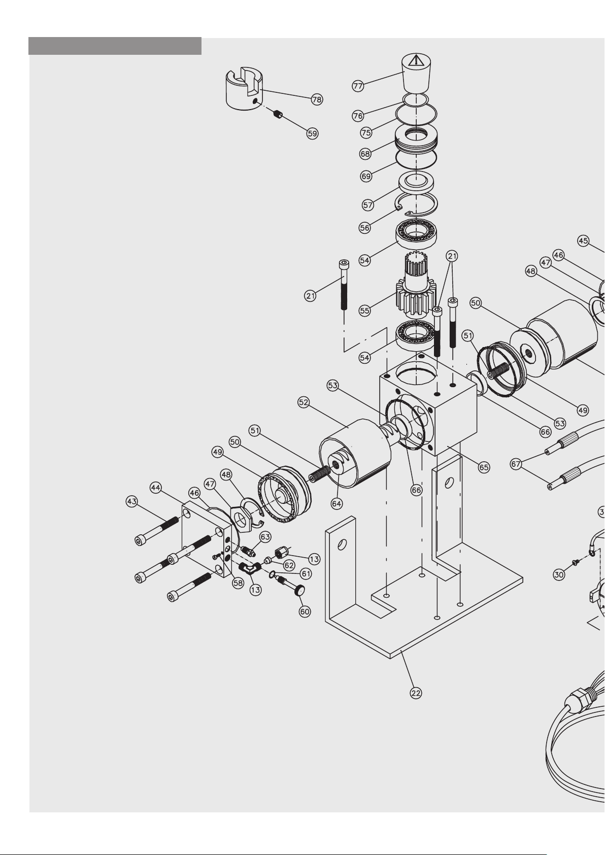
CLASSIC PLUS
22
Page 23
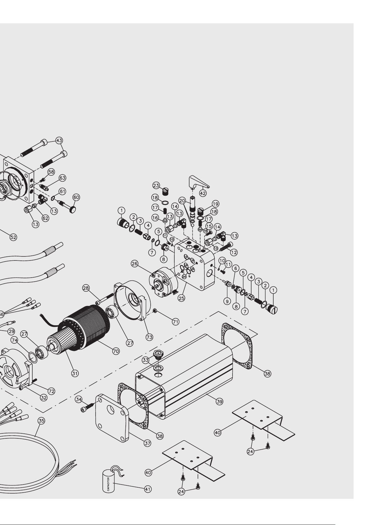
23
Page 24

CATALOGO
I F E
RICAMBI
CATALOGUE DES
RECHANGES
CATÁLOGO DE
RECAMBIOS
Nr. Cod. Distinta base CLASSIC/I PLUS Liste base CLASSIC/I PLUS Lista de materiales CLASSIC/I
1 TAP0012 Tappo lat. Per dist. CH Bouchon lat. Pour entr. CH Tapón lat. para distanciador CH
2 OR012M42X01M78 O. ring D.12.42x1.78 n°2050 Joint torique D.12.42x1.78 n°2050 Junta O-ring Ø 12.42x1.78 n°2050
3 MOS80A065X11 Molla di sblocco D.6.5 L11 Ressort de débrayage D.6.5 L11 Muelle de desbloqueo Ø 6.5 L11
4 9101900600 Sopporto O.R+O.R n°2021 Support Joint T. + Joint T. n°2021 Soporte O.R+O.R n°2021
5 OR010M82X01M78 O.ring D.10.82x1.78 n°2043 Joint torique D.10.82x1.78 n°2043 Junta O-ring Ø 10.82x1.78 n°2043
6 OR006M75X01M78 O. ring D.6.75x1.78 n°106 Joint torique D.6.75x1.78 n°106 Junta O-ring Ø 6.75x1.78 n°106
7 OR005M28X01M78 O.ring D.5.28 x1.78 n°2021 Joint torique D.5.28 x1.78 n°2021 Junta O-ring Ø 5.28 x1.78 n°2021
8 9262005300 Portasfera per dist. Irrev. CH/BLUES Porte-bille pour entr. Irrév. CH/BLUES Portabola para dist. Irrev. CH/BLUES
9 9285001400 Cursore per dist. CH/BLUES Curseur pour entr. CH/BLUES Cursor para dist. CH/BLUES
10 OR003M68X01M78 O. ring n°2015 Joint torique n°2015 Junta O-ring n°2015
11 VTT040X0080SZC Vite M4x8 tril. TPS+ Vis M4x8 tril. TPS+ Tornillo M4x8 mariposa TPS+
12 VTM040X0400CZCE Vite M6x40 UNI 5931 TCCE Vis M6x40 UNI 5931 TCCE Tornillo M6x40 UNI 5931 TCCE
13 9285000900 Raccordo 1/8 a gomito a 90° Raccord 1/8 coudé à 90° Racor 1/8 en codo de 90°
14 9285003000 Ogiva in rame D.8 Ogive en cuivre D.8 Ojiva de cobre Ø 8
15 VTM040X0060SZCE Vite M4X6 UNI 5933 TPSE zinc. Vis M4X6 UNI 5933 TPSE zing. Tornillo M4X6 UNI 5933 TPSE galvanizado
16 9352007500 Valvola piolino in AVP per BLUES/CH Vanne en AVP pour BLUES/CH Válvula de AVP para BLUES/CH
17 MOR Molla reg. valvola per BLUES/CH Ressort rég. Vanne pour BLUES/CH Molla reg. válvula para BLUES/CH
18 OR009M25X01M78 O. Ring D.9.25x1.78 n°2037 Joint torique D.9.25x1.78 n°2037 Junta O-ring Ø 9.25x1.78 n°2037
19 TAP0011 Tappo di reg. CH in ottone Bouchon de rég. CH en laiton Tapón de reg. CH de latón
20 MAN0007 Manopola di sblocco CLASSIC ass. Manille de déblocage CLASSIC ass. Volante de desbloqueo CLASSIC
21 VTM080X0900CZCE Vite M8X90 UNI 5931 TCCE zinc. Vis M8X90 UNI 5931 TPSE zing. Tornillo M8X90 UNI 5931 TCCE galvanizado
22 PIASMCLASSICZ Piastra di sup.mart. CLASSIC PLUS zinc. Plaque de sup. vérin CLASSIC PLUS zing. Placa de sop. gato CLASSIC PLUS galv.
23 TAP0010 Tappo di regolazione CH in alluminio Bouchon de réglage CH en aluminium Tapón de regulación CH de aluminio
24 VTM040X0080SIC Vite M4X8 TPS inox Vis M4X8 TPS inox Tornillo M4X8 TPS acero inox.
25 DISTRAA Distributore per CLASSIC anod. Distributeur pour CLASSIC anod. Distribuidor para CLASSIC anod.
26 PMP00M75 Pompa a lobi compl. Da 0.75L/min. Pompe à lobes compl. De 0.75L/min. Bomba lobular compl. de 0.75L/min.
27 CUSC6001ZZA Cuscinetto D.12x28x8 n°6001 ZZ Roulement D.12x28x8 n°6001 ZZ Cojinete 12x28x8 n°6001 ZZ
28 VTM050X0450CZCE Vite M5x45 UNI 5931 TCCE zinc Vis M5x45 UNI 5931 TCCE zing. Tornillo M5x45 UNI 5931 TCCE galvanizado
29 CAVO0005 Cavo G/V BLUES/CH Câble G/V BLUES/CH Cable G/V BLUES/CH
30 VTT040X0060CZC Vite M4x6 tril. TC+ zinc. Vis M4x6 tril. TC+ zing. Tornillo M4x6 mariposa TC+ galvanizado
31 ROT800001 Rotore + alb. Per BLUES Rotor + arb. Pour BLUES Rotor + eje para BLUES
32 VTM040X0700CIC Vite M4x70 UNI 6107 TC+ zinc. Vis M4x70 UNI 6107 TC+ zinc. Tornillo M4x70 UNI 6107 TC+ galvanizado
33 9352003700 Spia livello olio 3/8 gas 3892 Indicateur de niveau huile 3/8 gaz 3892 Indicador de nivel aceite 3/8 gas 3892
34 VTT060X0200CICE Vite M6x20 TCCE trilob. Zinc. Vis M6x20 TCCE trilob. zing. Tornillo M6x20 TCCE mariposa Galvanizado
35 CAB0007 Cablaggio per CLASSIC L=2.5 mt. Câblage pour CLASSIC L=2.5 m. Cables para CLASSIC L=2.5 mt.
36 9799904760 Capicorda maschio BM00130 D.1.5 Cosse mâle BM00130 D.1.5 Terminal de cable macho BM00130 Ø 1.5
37 CALLSB Calotta sup. per CLASSIC anod. Calotte sup. pour CLASSIC anod. Casquillo soporte para CLASSIC anod.
38 GUA0004 Guarnizione per BLUES/CH Joint pour BLUES/CH Junta para BLUES/CH
39 SERG0V Serbatoio per CH anod. Réservoir pour CH anod. Depósito para CH anod.
40 STA0007 Staffetta di fix CLASSIC A/2 inox Petite patte de fix CLASSIC A/2 inox Placa de fij. CLASSIC A/2 acero inox.
41 9422510040 Cond. Poli 8uF 450V con cavetti Climat. Poli 8uF 450V avec câblots Condensador Poli 8uF 450V con cables
42 9180007500 Chiave di sblocco TELCOMA Clé de débrayage TELCOMA Llave de desbloqueo TELCOMA
43 VTM080X0700CZCE Vite M8x70 UNI 5931 TCCE zinc. Vis M8x70 UNI 5931 TCCE zinc. Tornillo M8x70 UNI 5931 TCCE galvanizado
44 FLBF0E Flangia SX per MITHO Bride gauche pour MITHO Brida izq. para MITHO
45 FLDF0E Flangia DX per MITHO Bride droite pour MITHO Brida dcha para MITHO
46 OR066M40X01M78 O.Ring D.66.4x1.78 n°2262 Joint torique D.66.4x1.78 n°2262 Junta O-ring Ø 66.4x1.78 n°2262
47 RONSM0002 Rond. Per rallentamento MITHO Rond. Pour ralentissement MITHO Arandela para desaceleración MITHO
48 SEG42IF Anello seeger D.42 UNI 7437 Anneau Seeger D.42 UNI 7437 Arandela seeger Ø 42 UNI 7437
49 GUA0005 Guarnizione SDE 70x60x7.2 NORDEX Joint SDE 70x60x7.2 NORDEX Junta SDE 70x60x7.2 NORDEX
50 9285000200 Pistone per martinetto MITHO Piston pour vérin MITHO Pistón para gato MITHO
51 GR12X030EPZ Grano M12x30 UNI 5923 grezzo Goujon M12x30 UNI 5923 brut Pasador M12x30 UNI 5923
*52 CILF1Z Cilindro MITHO 120° 75x70 H=63 Cylindre MITHO 120° 75x70 H=63 Cilindro MITHO 120° 75x70 H=63
53 GUA0003 Guarnizione d.70x75 SP. 0.5 Joint d.70x75 ÉP. 0.5 Junta Ø 70x75 ESP. 0.5
54 CUSC60062RSA Cuscinetto D.30x55x13 n°6006 2RS Roulement D.30x55x13 n°6006 2RS Cojinete Ø 30x55x13 n°6006 2RS
55 ALBSF0G Albero per MITHO 120°/180° Arbre pour MITHO 120°/180° Eje para MITHO 120°/180°
56 SEG55IF Anello seeger D.55 UNI 7437 Anneau Seeger D.55 UNI 7437 Arandela seeger Ø 55 UNI 7437
57 PA30X47X6BAUDFSF Paraolio D.30x47x6 BADUOOFSFX7 Déflecteur de l'huile D.30x47x6 BADUOOFSFX7 Sello de aceite Ø 30x47x6 BADUOOFSFX7
58 VTT040X0080SZC Vite M4x8 trilob. TPS+ zinc. Vis M4x8 trilob. TPS+ zing. Tornillo M4x8 mariposa TPS+ galvanizado
59 GR08X008EPZ Grano M8X8 UNI 5923 zinc. Goujon M8X8 UNI 5923 zinc. Pasador M8X8 UNI 5923 galvanizado
60 9230001700 Vite reg. freno MITHO Vis rég. Frein MITHO Tornillo reg. freno MITHO
61 OR005M28X01M78 O.Ring D.5.28x1.78 n°2021 Joint torique D.5.28x1.78 n°2021 Junta O-Ring Ø 5.28x1.78 n°2021
62 9285003000 Ogiva in rame D.8 Ogive en cuivre D.8 Ojiva de cobre Ø 8
63 9230001600 Vite di sfiato per MITHO Vis d'évent pour MITHO Tornillo de purga para MITHO
*64 CREMF1L Crem. Per MITHO 120° L=109 lav. Crém. Pour MITHO 120° L=109 us. Crem. para MITHO 120° L=109 mecaniz.
65 CORFF0E Corpo centrale MITHO Corps central MITHO Cuerpo central MITHO
66 BR0010 Bronzina per MITHO D.34x30 L=8 Coussinet en bronze pour MITHO D.34x30 L=8 Buje para MITHO Ø 34x30 L=8
67 TUB009 Tubo R7 3/16 D.8 raccord. L=800 Tuyau R7 3/16 D.8 raccord. L=800 Tubo R7 3/16 Ø 8 racor L=800
68 9266002500 Coprimozzo per MITHO Couvre-moyeu pour MITHO Tapa cubo para MITHO
69 OR050M47X02M62 O.ring D.50.47x2.62 N°3200 Joint torique D.50.47x2.62 N°3200 Junta O-Ring Ø 50.47x2.62 N°3200
70 STAT800001 Stat. D.80x45 H50 BLUES Stat.S D.S80x45 H50 BLUES Estator Ø 80x45 H50 BLUES
71 DA04Z0 Dado M4 UNI 5588 Écrou M4 UNI 5588 Tuerca M4 UNI 5588
72 9293000700 Calottina post. Mot. BLUES Petite calotte post. Mot. BLUES Tapa trasera Mot. BLUES
73 9293000600 Calottina ant. Mot. BLUES Petite calotte ant. Mot. BLUES Tapa delantera Mot. BLUES
74 AC27M8X0M3 Anello di compensazione D.27.8 SP.0.3 Bague de compensation D.27.8 ÉP.0.3 Anillo de compensación Ø 27.8 ESP.0.3
75 OR050M39X03M53 O.ring D.50.39x3.53 N°4200 Joint torique D.50.39x3.53 n°4200 Junta O-Ring Ø 50.39x3.53 N°4200
76 OR029M82X02M62 O.ring D.29.82x2.62 N°3118 Joint torique D.29.82x2.62 n°3118 Junta O-Ring Ø 29.82x2.62 N°3118
77 9180006700 Cappuccio albero scanalato martinetto serig. Capuchon arbre rainuré vérin sérig. Tapa eje acanalado gato con serig.
78 SBUSICAPPLUSZ Bussola inferiore x CAP PLUS zinc. Douille inférieure pour CAP PLUS zinc. Casquillo inferior x CAP PLUS galvanizado
24
Page 25

CATALOGO
I F E
RICAMBI
CATALOGUE DES
RECHANGES
CATÁLOGO DE
RECAMBIOS
Nr. Cod. Distinta base CLASSIC/I PLUS Liste base CLASSIC/I PLUS Lista de materiales CLASSIC/I
*52 CILF5Z Cilindro MITHO 180° 75x70 H=91 Cylindre MITHO 180° 75x70 H=91 Cilindro MITHO 180° 75x70 H=91
*64 CREMF5L Crem. Per MITHO 180° L=137 lav. Crém. Pour MITHO 180° L=137 us. Cremallera para MITHO 180° L=137 mec.
I particolari : 3, 4, 7; mancano sui reversibili Los detalles: 3, 4, 7; faltan en los reversibles
PARTICOLARI ASSIEMATI DISPONIBILI: PIÉCES ASSEMBLÉES DISPONIBLES: DETALLES ENSAMBLADOS DISPONIBLES:
A MITHO120 Martinetto MITHO 120° ass. (13,43 →) 66) Vérin MITHO 120° ass. (13,43 →) 66) Gato MITHO 120° ensamb. (13,43 →) 66)
B MITHO180 MITHO 180 (13,43 →) 66) MITHO 180 (13,43 →) 66) MITHO 180 (13,43 →) 66)
C SCHICLASSIC CHI per CLASSIC 120°/180° ASS. (1 →) CHI pour CLASSIC 120°/180° ASS. (1 →) CHI para CLASSIC 120°/180° ENSAMB. (1 →)
43) NO:15, 40, 41, 42 43) NO:15, 40, 41, 42 43) NO:15, 40, 41, 42
D CHR CHR per CLASSIC 120°/180° ASS. (1 →) CHR pour CLASSIC 120°/180° ASS. (1 →) CHR para CLASSIC 120°/180° ENSAMB. (1 →
43) NO: 3, 4, 7, 15, 40, 41, 42 43) NO: 3, 4, 7, 15, 40, 41, 42 43) NO: 3, 4, 7, 15, 40, 41, 42
E DISTRDB Distributore CLASSIC/I ass. (1 →) 25) Distributeur CLASSIC/I ass. (1 →) 25) Distribuidor CLASSIC/I ensamb. (1 →) 25)
NO: 21,22,24 NO: 21,22,24 NO: 21,22,24
F DISTRCB Distributore CLASSIC/R ass. (1 →) 25) Distributeur CLASSIC/R ass. (1 →) 25) Distribuidor CLASSIC/R ensamb. (1 →) 25)
NO: 3,4,7,21,22,24 NO: 3,4,7,21,22,24 NO: 3,4,7,21,22,24
G 9105100800 Motore CLASSIC/BLUES ass. Moteur CLASSIC/BLUES ass. Motor CLASSIC/BLUES ensamb.
Les pièces : 3, 4, 7; ne sont pas présentes
sur les réversibles
25
Page 26

GB D NL
CATALOGUE
SPARE PARTS
ERSATZTEILKATALOG CATALOGUS MET
RESERVEONDERDELE
Nr. Cod. CLASSIC/I PLUS spare parts CLASSIC/I PLUS ersatzteile CLASSIC/I PLUS reserveonderdelen
1 TAP0012 Lat. plug for spacer CH Seitl. Stopfen für Dist. CH Dop zijkant voor afstandsstuk CH
2 OR012M42X01M78 D.12.42x1.78 No. 2050 O.ring O-Ring D.12.42x1.78 Nr. 2050 O-ring D.12.42x1.78 nr.2050
3 MOS80A065X11 D.6.5 L11 release spring Entriegelungsfeder D.6.5 L11 Ontgrendelingsveer D.6.5 L11
4 9101900600 No. 2021 O.R+O.R support Halterung O.R+O.R Nr. 2021 Houder O.R+O.R nr.2021
5 OR010M82X01M78 D.10.82x1.78 No. 2043 O.ring O-Ring D.10.82x1.78 Nr. 2043 O-ring D.10.82x1.78 nr.2043
6 OR006M75X01M78 D.6.75x1.78 No. 106 O. ring O-Ring D.6.75x1.78 Nr. 106 O-ring D.6.75x1.78 nr.106
7 OR005M28X01M78 D.5.28 x1.78 No. 2021 O.ring O-Ring D.5.28 x1.78 Nr. 2021 O-ring D.5.28 x1.78 nr.2021
8 9262005300 Ball holder for irrev. spacer CH/BLUES Kugelhalter für Dist. Selbsthem. CH/BLUES Kogelhouder voor afstandsstuk onomkeerbaar
9 9285001400 Slider for spacer CH/BLUES Schieber für Dist. CH/BLUES Cursor voor afstandsstuk CH/BLUES
10 OR003M68X01M78 No. 2015 O. ring O-Ring Nr. 2015 O-ring nr.2015
11 VTT040X0080SZC M4x8 tri-lobed. screw TPS+ Schraube M4x8 dreibuckelig TPS+ Schroef M4x8 tril. TPS+
12 VTM040X0400CZCE M6x40 UNI 5931 TCCE screw Schraube M6x40 UNI 5931 Inbus-Zylinderkopf Schroef M6x40 UNI 5931 TCCE
13 9285000900 1/8 90° union elbow Anschluss 1/8, 90° Knie Kniekoppeling 1/8 90°
14 9285003000 D.8 copper hub Kupferkegel D.8 Knelring uit koper D.8
15 VTM040X0060SZCE M4X6 UNI 5933 TPSE galv. screw Schraube M4X6 UNI 5933 TPSE verzinkt Schroef M4X6 UNI 5933 TPSE verzinkt
16 9352007500 BLUES/CH AVP valve Ventil aus AVP für BLUES/CH Klep uit AVP voor BLUES/CH
17 MOR BLUES/CH valve adj. spring Ventilregelfeder für BLUES/CH Veer afstelling klep voor BLUES/CH
18 OR009M25X01M78 D.9.25x1.78 No. 2037 O. Ring O-Ring D.9.25x1.78 Nr. 2037 O-Ring D.9.25x1.78 nr.2037
19 TAP0011 CH brass adj. plug Regelstopfen CH aus Messing Regeldop CH uit brons
20 MAN0007 Ass. CLASSIC release knob Entriegelungsknauf CLASSIC montiert Ontgrendelingsknop CLASSICgeassembleerd
21 VTM080X0900CZCE M8X90 UNI 5931 TCCE galv. screw Schraube M8X90 UNI 5931 Schroef M8X90 UNI 5931 TCCE verzinkt
Inbus-Zylinderkopf verzinkt
22 PIASMCLASSICZ CLASSIC PLUS galv. jack support plate Kolbentragplatte CLASSIC PLUS verzinkt Steunplaat bed.cil. CLASSIC PLUS verzinkt
23 TAP0010 CH aluminium adjustment plug Regelstopfen CH aus Aluminium Regeldop CH uit aluminium
24 VTM040X0080SIC M4X8 TPS stainless steel screw Schraube M4X8 TPS Inox Schroef M4X8 TPS inox
25 DISTRAA CLASSIC anod. distributor Verteiler für CLASSIC eloxiert Verdeler voor CLASSIC geanod.
26 PMP00M75 0.75L/min. positive displacement pump Nockenpumpe kompl. 0.75l/Min. Pomp met bladen compl. van 0,75l/min.
27 CUSC6001ZZA D.12x28x8 No. 6001 ZZ bearing Lager D.12x28x8 Nr. 6001 ZZ Lager D.12x28x8 nr.6001 ZZ
28 VTM050X0450CZCE M5x45 UNI 5931 TCCE galv. screw Schraube M5x45 UNI 5931 Schroef M5x45 UNI 5931 TCCE verzinkt
Inbus-Zylinderkopf verzinkt
29 CAVO0005 G/V BLUES/CH cable Kabel G/V BLUES/CH Kabel G/V BLUES/CH
30 VTT040X0060CZC M4x6 tri-lobed TC+ galv. screw Schraube M4x6 dreibuck. Zylinderkopf + verzinkt Schroef M4x6 tril. TC+ verzinkt
31 ROT800001 BLUES rotor + shaft Rotor + Welle für BLUES Rotor + as voor BLUES
32 VTM040X0700CIC M4x70 UNI 6107 TC+ galv. screw Schraube M4x70 UNI 6107 Zylinderkopf + verzinkt Schroef M4x70 UNI 6107 TC+ verzinkt
33 9352003700 3/8 oil level indicator 3892 gas Ölschauglas 3/8 Gas 3892 Kijkglas oliepeil 3/8 gas 3892
34 VTT060X0200CICE M6x20 TCCE tri-lobed galv. screw Schraube M6x20 TCCE dreibuck. verzinkt Schroef M6x20 TCCE driebl. verzinkt.
35 CAB0007 CLASSIC L=2.5 mt. cable Verdrahtung für CLASSIC L=2.5 m Bekabeling voor CLASSIC L=2,5 m
36 9799904760 BM00130 D.1.5 male terminal Male-Endverschluss BM00130 D.1.5 Kabelschoen BM00130 D.1.5
37 CALLSB CLASSIC anod. upper cover Obere Haube für CLASSIC eloxiert Afdekkap boven voor CLASSIC geanod.
38 GUA0004 BLUES/CH seal Dichtung für BLUES/CH Dichting voor BLUES/CH
39 SERG0V CH anod. tank Tank für CH eloxiert Reservoir voor CH geanod.
40 STA0007 CLASSIC A/2 stainless steel fixing bracket Bef.Bügel CLASSIC A/2 Inox Bevestigingsbeugeltje CLASSIC A/2 inox
41 9422510040 8uF 450V pole condenser with cable Kondensator Pole 8uF 450V mit Drähten Condensator Polen 8uF 450V met kabeltjes
42 9180007500 TELCOMA release key Entriegelungsschlüssel TELCOMA Ontgrendelingssleutel TELCOMA
43 VTM080X0700CZCE M8x70 UNI 5931 TCCE galv. screw Schraube M8x70 UNI 5931 Schroef M8x70 UNI 5931 TCCE verzinkt
Inbus-Zylinderkopf verzinkt
44 FLBF0E MITHO LH flange Flansch LI für MITHO Flens links voor MITHO
45 FLDF0E MITHO RH flange Flansch RE für MITHO Flens rechts voor MITHO
46 OR066M40X01M78 D.66.4x1.78 No. 2262 O.Ring O-Ring D.66.4x1.78 Nr. 2262 O-ring D.66.4x1.78 nr.2262
47 RONSM0002 MITHO deceleration washer Unterlegscheibe f. Verlangsamung MITHO Borgring voor vertraging MITHO
48 SEG42IF D.42 UNI 7437 snap ring Seegerring D.42 UNI 7437 Seegerring D.42 UNI 7437
49 GUA0005 SDE 70x60x7.2 NORDEX seal Dichtung SDE 70x60x7.2 NORDEX Dichting SDE 70x60x7.2 NORDEX
50 9285000200 MITHO jack piston Kolben für Zylinder MITHO Zuiger voor bedieningscilinder MITHO
51 GR12X030EPZ M12x30 UNI 5923 untreated dowel Stift M12x30 UNI 5923 unbearbeitet Stifttap M12x30 UNI 5923 ruw
*52 CILF1Z MITHO 120° 75x70 H=63 cylinder Zylinder MITHO 120° 75x70 H=63 Cilinder MITHO 120° 75x70 H=63
53 GUA0003 D.70x75 SP. 0.5 seal Dichtung D.70x75 St. 0.5 Dichting d.70x75 SP. 0.5
54 CUSC60062RSA D.30x55x13 No. 6006 2RS bearing Lager D.30x55x13 Nr. 6006 2RS Lager D.30x55x13 nr.6006 2RS
55 ALBSF0G MITHO 120°/180° shaft Welle für MITHO 120°/180° As voor MITHO 120°/180°
56 SEG55IF D.55 UNI 7437 snap ring Seegerring D.55 UNI 7437 Seegerring D.55 UNI 7437
57 PA30X47X6BAUDFSF D.30x47x6 BADUOOFSFX7 oil guard Ölabdichtung D.30x47x6 BADUOOFSFX7 Oliekering D.30x47x6 BADUOOFSFX7
58 VTT040X0080SZC M4x8 tri-lob. TPS+ galv. screw Schraube M4x8 dreibuck. Senkflachkopf + verzinktSchroef M4x8 drieblad. TPS+ verzinkt
59 GR08X008EPZ M8X8 UNI 5923 galv. dowel Stift M8X8 UNI 5923 verzinkt Stifttap M8X8 UNI 5923 verzinkt
60 9230001700 MITHO brake adjustment screw Bremse Stellschraube MITHO Stelschroef rem MITHO
61 OR005M28X01M78 D.5.28x1.78 No. 2021 O.Ring O-Ring D.5.28x1.78 Nr. 2021 O-ring D.5.28x1.78 nr.2021
62 9285003000 D.8 copper hub Kupferkegel D.8 Knelring uit koper D.8
63 9230001600 MITHO bleed screw Entlüfterschraube für MITHO Ontluchtingsschroef voor MITHO
*64 CREMF1L MITHO 120° L=109 mach. rack Zahnst. für MITHO 120° L=109 bearb. Tandheugel voor MITHO 120° L=109 bewerkt
65 CORFF0E MITHO central casing zentraler Körper MITHO Middendeel MITHO
66 BR0010 MITHO D.34x30 L=8 bushing Bronzelager für MITHO D.34x30 L=8 Kussenblok voor MITHO D.34x30 L=8
67 TUB009 R7 3/16 D.8 L=800 pipe union Rohr R7 3/16 D.8 Anschluss L=800 Buis R7 3/16 D.8 koppeling. L=800
68 9266002500 MITHO hub cap Nabenabdeckung für MITHO Naafdop voor MITHO
69 OR050M47X02M62 D.50.47x2.62 No. 3200 O.ring O-Ring D.50.47x2.62 Nr. 3200 O-ring D.50.47x2.62 nr.3200
70 STAT800001 D.80x45 H50 BLUES stator Stator D.80x45 H50 BLUES Stator D.80x45 H50 BLUES
71 DA04Z0 M4 UNI 5588 nut Mutter M4 UNI 5588 Moer M4 UNI 5588
72 9293000700 BLUES rear mot. cover Hint. Motorhaube BLUES Afdekkapje achter motor BLUES
73 9293000600 BLUES front motor cover Vord. Motorhaube Mot. BLUES Afdekkapje voor motor BLUES
74 AC27M8X0M3 D.27.8 SP.0.3 compensating ring Kompensationsring D.27.8 SP.0.3 Compensatiering D.27.8 SP.0.3
CH/BLUES
26
Page 27

GB D NL
CATALOGUE
SPARE PARTS
ERSATZTEILKATALOG CATALOGUS MET
RESERVEONDERDELE
Nr. Cod. CLASSIC/I PLUS spare parts CLASSIC/I PLUS ersatzteile CLASSIC/I PLUS reserveonderdelen
75 OR050M39X03M53 D.50.39x3.53 No. 4200 O.ring O-Ring D.50.39x3.53 Nr. 4200 O-ring D.50.39x3.53 nr.4200
76 OR029M82X02M62 D.29.82x2.62 No. 3118 O.ring O-Ring D.29.82x2.62 Nr. 3118 O-ring D.29.82x2.62 nr.3118
77 9180006700 Screen printed jack spline shaft cap Kappe f. Keilwelle siebgedr. Kolben Kapje gegroefde as bedieningscilinder xerig.
78 SBUSICAPPLUSZ CAP PLUS lower galv. bush Untere Büchse x CAP PLUS verzinkt Kussenblok onder voor CAP PLUS verzinkt
*52 CILF5Z MITHO 180° 75x70 H=91 cylinder Zylinder MITHO 180° 75x70 H=91 Cilinder MITHO 180° 75x70 H=91
*64 CREMF5L MITHO 180° L=137 mach. rack Zahnstange für MITHO 180° L=137 bearb. Tandheugel voor MITHO 180° L=137 lav.
Items: 3, 4, 7; not available for reversible Die Teile 3, 4, 7 fehlen an den nicht De onderdelen : 3, 4, 7; ontbreken op de
models selbsthemmenden Modellen. Omkeerbare
AVAILABLE ASSEMBLED PARTS: LIEFERBARE MONTIERTE TEILE: LEVERBARE GEASSEMBLEERDE
A MITHO120 Ass. MITHO 120° jack (13,43 →) 66) Zylinder MITHO 120° montiert (13,43 →) 66) Bedieningscilinder MITHO 120° geassembleerd
B MITHO180 MITHO 180 (13.43 →) 66) MITHO 180 (13,43 →) 66) MITHO 180 (13,43 →) 66)
C SCHICLASSIC ASS. CHI for CLASSIC 120°/180° (1 →) CHI für CLASSIC 120°/180° montiert(1 →) CHI voor CLASSIC 120°/180° geassembleerd
43) NO:15, 40, 41, 42 43) OHNE:15, 40, 41, 42 (1 →) 43) NR:15, 40, 41, 42
D CHR ASS. CHR for CLASSIC 120°/180° CHR für CLASSIC 120°/180° montiert CHR voor CLASSIC 120°/180° geassembleerd
(1 →) 43) NO: 3, 4, 7, 15, 40, 41, 42 (1 →) 43) OHNE: 3, 4, 7, 15, 40, 41, 42 (1 →) 43) NR: 3, 4, 7, 15, 40, 41, 42
E DISTRDB CLASSIC/I distributor (1 →) 25) NO: 21,22,24 Verteiler CLASSIC/I montiert Verdeler CLASSIC/I geassembleerd
(1 →) 25) OHNE: 21,22,24 (1 →) 25) NR: 21,22,24
F DISTRCB Ass. CLASSIC/R distributor Verteiler CLASSIC/R montiert Verdeler CLASSIC/R geassembleerd
(1 →) 25) NO: 3,4,7,21,22,24 (1 →) 25) OHNE: 3,4,7,21,22,24 (1 →) 25) NR: 3,4,7,21,22,24
G 9105100800 Ass. CLASSIC/BLUES motor Motor CLASSIC/BLUES montiert Motor CLASSIC/BLUES geassembleerd
ONDERDELEN:
(13,43 →) 66)
27
Page 28

AUTOMATISMI PROFESSIONALI PER CANCELLI E GARAGE
PROFESSIONAL GARAGE DOOR AND GATE OPERATORS
DICHIARAZIONE CE
Il fabbricante:
Telcoma srl
Via L. Manzoni, 11
31015 - Z.I. Campidui - Conegliano (TV)
ITALY
DICHIARA che il prodotto
MOTORIDUTTORE
“CLASSIC PLUS”
è conforme alle condizioni delle seguenti direttive CEE:
● Direttive 73/23 CEE Direttiva 93/68 CEE
Bassa Tensione
● Direttiva 89/336 CEE Direttiva 92/31 CEE
Direttiva 92/31 CEE compatibilità
Elettromagnetica
e che:
sono state applicate le seguenti (parti/clausole) di norme
armonizzate:
EN60335-1, EN 60204-1, EN 61000-6-3,
EN61000-6-1
DECLARATION CE
The manufacturer:
Telcoma srl
Via L. Manzoni, 11
31015 - Z.I. Campidui - Conegliano (TV)
ITALY
DECLARES that the products
GEAR MOTOR DRIVE UNIT
“CLASSIC PLUS”
are however conforming to the only applicable parts of
this directive;
● Directive 73/23/EEC, Directive 93/68/EEC
Low Voltage
● Directive 89/336/EEC, Directive 92/31/EEC
Directive 92/31/EEC Electromagnetic
Compatibility
The following parts/clauses of the harmonised regulations
have been applied:
EN60335-1, EN60204-1, EN 61000-6-3,
EN61000-6-1
e per le sole parti applicabili le norme
EN12445 e EN12453
DICHIARAZIONE DEL FABBRICANTE
(Direttiva 98/37 CEE Allegato II, Parte B)
Il prodotto è costruito per essere incorporati in una
macchina o per essere assemblati con altri macchinari
per costruire una macchina considerata dalla Direttiva
98/37 CEE
E inoltre dichiara che non è consentito mettere in servizio
il prodotto fino a che la macchina in cui saranno
incorporati o di cui diverranno componenti sia stata
identificata e ne sia stata dichiarata la conformità alle
condizioni della Direttiva 98/87 CEE e alla legislazione
nazionale che lo traspone, vale a dire fino a che il
prodotto di cui alla presente dichiarazione non formi un
complesso unico con la macchina finale.
Conegliano, lì 03/06/2006
and for the only applicable parts the norms
EN12445 e EN12453
DECLARATION BY THE MANUFACTURER
(Directive 98/37/EEC, Attachment II, Part B)
Have been constructed to be incorporated in a machine
or to be assembled with other machinery to construct a
machine as set out in Directive 98/37/EEC
The manufacturer furthermore declares that it is not
permitted to operate the products until the machine in
which they will be incorporated or of which they will
become components has been identified and its
conformity with the provisions set out in Directive
98/37/EEC and the national legislation has been
declared, i.e. until the products as set forth in this
declaration form a single unit with the final machine.
Conegliano, lì 03/06/2006
28
Legale rappresentante
Augusto Silvio Brunello
Legal representative
Augusto Silvio Brunello
Page 29

I F E
SMALTIMENTO ELIMINATION ELIMINACION
Questo prodotto è formato da vari componenti che
potrebbero a loro volta contenere sostanze
inquinanti. Non disperdere nell'ambiente!
Informarsi sul sistema di riciclaggio o smaltimento del
prodotto attenendosi alle norme di legge vigenti a
livello locale.
Ce produit est constitué de divers composants qui
pourraient à leur tour contenir des substances
polluantes. Ne pas laisser ce produit gagner
l'environnement.
S'informer sur le système de recyclage ou
d'élimination du produit conformément aux
dispositions légales en vigueur à un niveau local.
Este producto está constituido por varios
componentes que podrían, a su vez, contener
sustancias contaminantes. ¡No los vierta en el
medio ambiente!
Infórmese sobre el sistema de reciclaje o
eliminación del producto con arreglo a las leyes
vigentes en ámbito local.
GB D NL
DISPOSAL ENTSORGUNG VERWIJDERING
This product is made up of various components
that could contain pollutants. Dispose of
properly!
Make enquiries concerning the recycling or
disposal of the product, complying with the local
laws in force.
Dieses Produkt besteht aus verschiedenen
Bauteilen, die ihrerseits die Umwelt
verschmutzende Stoffe enthalten können.
Sachgerecht entsorgen!
Informieren Sie sich, nach welchem Recyclingoder Entsorgungssystem das Produkt
entsprech e n d der ö r t lic h geltenden
Bestimmungen zu entsorgen ist
Dit product bestaat uit diverse onderdelen die
ook weer verontreinigende stoffen kunnen
bevatten. Het product mag niet zomaar
weggegooid worden!
Informeer over de wijze van hergebruik of
verwijdering van het product en neem daarbij de
wettelijke voorschriften die ter plaatse gelden in
acht.
29
Page 30

NOTES
30
Page 31

31
Page 32
CERTIFICATO DI GARANZIA
PRODOTTO
TIMBRO E/O FIRMA DELL’INSTALLATORE
DATA D’INSTALLAZIONE
%
I F E
GARANZIA GARANTIE GARANTIA
La presente garanzia copre gli eventuali guasti e/o anomalie
dovuti a difetti e/o vizi di fabbricazione. La garanzia decade
automaticamente in caso di manomissione o errato utilizzo del prodotto.
Durante il periodo di garanzia la ditta Telcoma srl si impegna
a riparare e/o sostituire le parti difettate e non manomesse.
Restano a intero ed esclusivo carico del cliente il diritto di
chiamata, nonché le spese di rimozione, imballo e
starsporto del prodotto per la riparazione e sostituzione.
Cette garantie couvre les éventuelles pannes et/ou
anomalies imputables à des défauts eou vis de fabrication.
La garantie s'annule automatiquement si le produit a été
modifié ou utilisé de maniére impropre. L'entreprise Telcoma
srl s'engange, durant la periode de garantie du produit, à
reparer et/ou remplacer les piéces defectueuses n'ayant
pas subi de modifications. Restent entièrement et
exclusivament à la charge du client, le droit d'appel ainsi que
les frais d'enleévement, d'emballage et de transport du
produit pour sa réparation ou substitution.
La presente garantia es válida en el caso cie averias y/o
anomaliás causadas por defectos y/o desperfectos de
fabricación. La garantia automáticamente pierde valor en el
caso de arreglos improprios o utilizactión equivocada del
producto. Durante el periodo de garantía, la empresa
Telcoma srl se compromete a reparar y/o cambiar la partes
defectuosas que no hayan sido dañadas. Quedan a total y
exclusivo cargo del cliente el derecho de llamada, como asi
también los gastos de extracción, embalaje y transporte del
producto para la raparación o cambio.
GB D NL
WARRANTY GARANTIE GARANTIE
This warranty covers any failure and/or malfunctioning due
to manifacturing faults and/or bad workmanship.
The warranty is automatically invalidated if the product is
tempered with or used incorrectly.
During the warranty period, Telcoma srl undertakes to repair
and/or replace faulty parts provided they have not been
temperd with.
The call-out charge as well as the expenses for
dasasembley, packing and transport of the product for repair
or replacement shall be charged entirely to the customer.
Telcoma srl - Via L. Manzoni, 11 - Z.I. Campidui
31015 Conegliano - (TV) Italy - Tel. +39 0438-451099
Fax +39 0438-451102 - Part. IVA 00809520265
Die vorliegende Garantie deckt eventuelle Defekte und/oder
Betriebsstörungen ab, die auf Fabricationsfehler
und/oder mängel zurück-zuführen sin. Die Garantie
verfällt automatisch im Falle von Manipulationen oder
fehlerhaftem Gebrauch des Produktes. Während der
Garantiezeit verpflichtet sich die Firma Telcoma srl, die
defekten und nicht manipulierten Teile zu reparieren
und/ oder auszut auschen. Die Auforderung des
Kundendienstes als auch die Kosten für die Abholung, die
Verpackung und den Transport des Produkten für die
Reparatur bzw den Austausch gehen zu vollen und
ausschliefßlichen Lasten des Kunden.
http://www.telcoma.it E-mail: info@telcoma .it
Deze garantie dekt eventuele storingen en/of defecten die te
wijten aan fabrieksfouten en/of gebreken. De garantie
vervalt automatisch indien de gebruiker zelf aan het produkt
gesleuteld heeft of veranderingen aangebracht heeft of
indien het produkt op verkeerde wijze gebruikt is. Tijdens de
garantietermijn neemt de Firma Telcoma srl de verplichting
op te defecte onderdelen te repareren en/of te vervangen
mits de gebruiker deze onderdelen niet zelf geprobeerd
heeft te repareren. De voorrijkosten alsmede de onkosten
voor het demonteren, het verpakken en verzenden van het
produkt te repareren of te vervangen zijn en blijven
uitsluitend voor rekening van de klant.
 Loading...