

Page 1
ISTBR6
I
F
E
GB
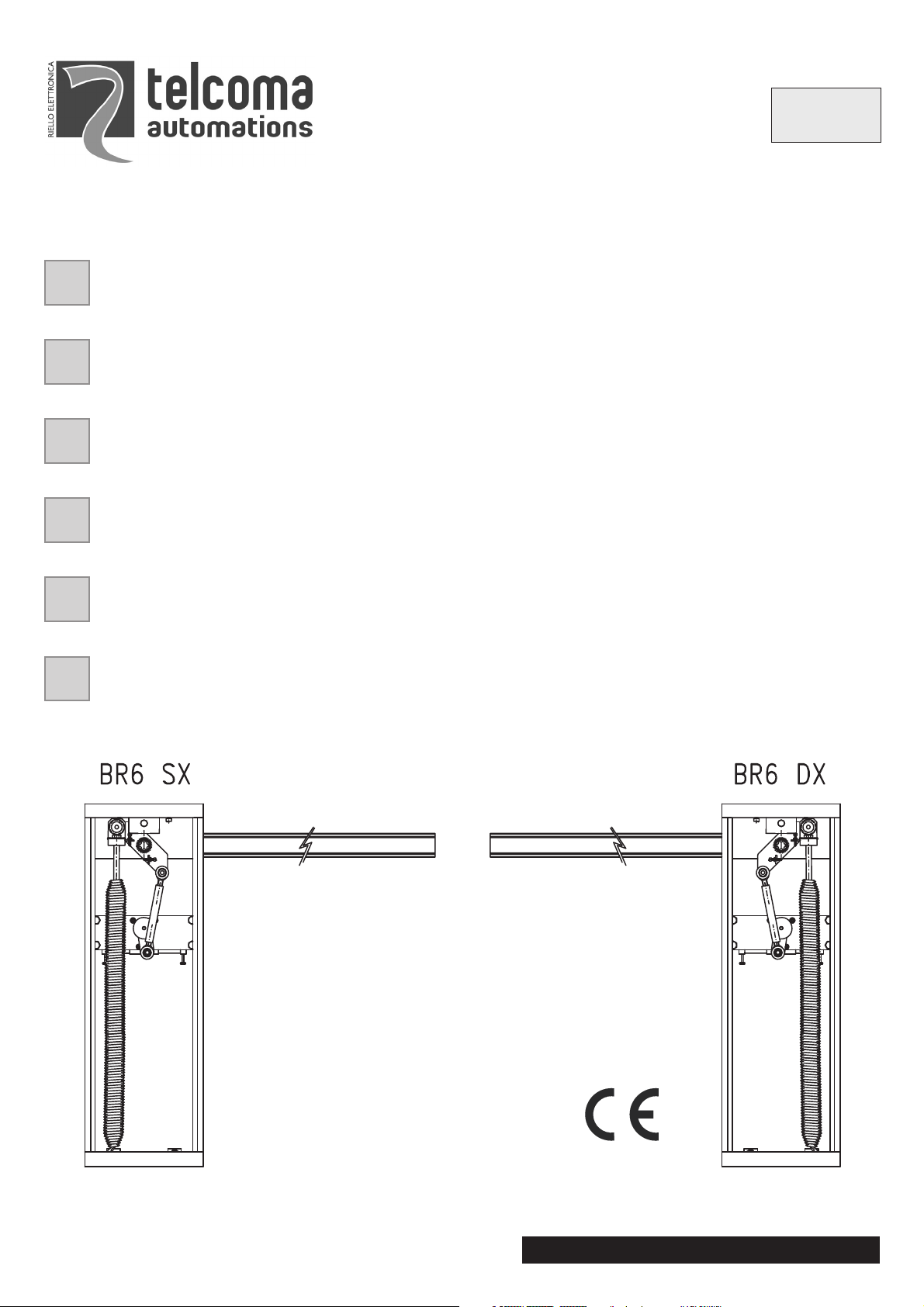
BR-6
BARRIERA OLEODINAMICA
MANUALE ISTRUZIONI E CATALOGO RICAMBI
IL PRESENTE LIBRETTO È DESTINATO AL PERSONALE TECNICO QUALIFICATO ALLE INSTALLAZIONI
BARRIÈRE HYDRAULIQUE
NOTICE D'INSTRUCTION ET CATALOGUE PIECES DE RECHANGE
CETTE NOTICE S'ADRESSE À DES TECHNICIENS SPÈCIALISÈS DANS L'INSTALLATION
BARRERA OLEODINÁMICA
MANUAL ISTRUCCIONES Y CATALOGO REPUESTOS
EL PRESENTE FOLLETO ESTÁ DESTINADO AL PERSONAL TECNICO ESPECIALIZADO EN INSTALACIONES
HYDRAULIC BARRIER
INSTRUCTION HANDBOOK AND SPARE PARTS CATALOGUE
THIS HANDBOOK IS INTENDED FOR QUALIFIED TECHNICAL INSTALLERS
V. 01.2008
D
NL
ÖLDYNAMISCHE SC HRANKE
BEDIENUNGANWEISUNGEN UND ERSATZTEILLISTE
DAS VORLIEGENDE HANDBUCH IST FÜR DAS MIT DER INSTALLATION BETRAUTE TECHNISCH QUALIFIZIERTE
FACHPERSONAL BESTIMMT
HYDRAULISCHE SLAGBOOM
GEBRUIKERSHANDLEIDING EN RESERVEONDERDELEN CATALOGUS
DEZE HANDLEIDING IS BESTEMD VOOR VAKBEKWAME INSTALLATEURS
Telcoma srl - Via L. Manzoni, 11 - Z.I. Campidui - 31015 Conegliano - (TV) Italy
Tel. +39 0438-451099 - Fax +39 0438-451102 - Part. IVA 00809520265
http://www.telcoma.it E-mail: info@telcoma .it
Page 2
I F E
CARATTERISTICHE
BR-6 è una barriera idraulica che trova impie-
go negli accessi a: parcheggi, autosilo, stabilimenti, enti pubblici, ospedali, edifici condominiali, etc.
E’ costituita da un armadietto, all’interno del
quale sonoalloggiatiil martinetto, lacentralina
idraulica e la centralina elettronica di comando.
Il movimento è irreversibile con possibilità di
sblocco manuale.
Accessori a richiesta
Struttura mobile a siepe
Piedino snodato di appoggio
Asta a profilo circolare Ø 90 L= 6,25m e rispettivo supporto asta
Asta a profilo rettangolare
Appoggio fisso per asta
CARACTERISTIQUES CARACTERISTICAS
BR-6 estune barrière hydrauliqueutiliséepour
les accès aux: parkings, parkings à étages,
usines, services publiques, hôpitaux,
immeubles, etc.
Elle est constituée d’une armoire à l’intérieur
de laquelle sont logés le vérin, la centrale
hydraulique et la centrale électronique de
commande.
Le mouvementestirréversible avec possibilité
de déblocage manuel.
Accessoires à la demande
Structure mobile en épi
Pied d’appui articulé
Barre àprofil circulaire Ø90L=6,25m et support
barre
Barre à profil rectangulaire
Appui fixe pour barre
BR-6 esuna barrera hidráulicaque se emplea
en los accesos a: aparcamientos, autosilo,
establecimientos, instituciones pùblicas,
hospitales, edificios de propiedad horizontal,
etc.
Estè constituida porun pequeño armario dentro del cual se encuentran el gato, el tablero
Hidráulico y el tablero electrónico de mando.
El movimientoesirreversible con laposibilidad
de desbloqueo manual.
Accesorios a pedido
Estructura móvil tipo valla.
Pié articulado de apoyo
Asta con perfil circular Ø 90 L= 6,25 m y
correspondiente soporte asta
Asta con perfil rectangular
Apoyo fijo para asta
GB
D NL
CHARACTERISTICS KENNDATEN KENMERKEN
BR-6 is a hydraulic barrier which can be used
in entrances to: car parks, multi-storey parks,
factories, public facilities, hospitals, blocks of
flats, etc.
It consists of a box which contains the jack,
hydraulic power unit and the electronic control
unit.
Movement is irreversiblewith the possibility of
manual release.
Optional accessories
Mobile fence-type frame
Jointed support foot
Circular barØ 90L= 6.25m and respective bar
support
Rectangular bar
Fixed bar rest
Bei BR-6 handelt es sich um eine
hydraulische Schranke, die ihreAnwendung
bei folgenden Zugängen findet: Parkplätze,
Parkhäuser, Gebäude, Behörden,
Krankenhäuser, Wohnhäuser usw.
Sie besteht aus einem Schrank, in welchem
der Hebebock, die hydraulische
Steuerzentrale und die elektronische
Steuerzentrale untergebracht sind.
Die Bewegung ist irreversible mit möglicher
manueller Entriegelung.
Sonderzubehör
Mobile Flechtzaun-Struktur
Gelenk-Stützfuß
Stange mit rundem Profil Ø 90, L = 6,25 m
und entsprechende Stangenstütze
Stange mit rechteckigem Profil
Feste Stangenauflage
De BR-6 is een hydraulische slagboom die
toegepast kan worden om respectievelijk
toegang te verlenen en te ontzeggen naar:
parkeerplaatsen, parkeergarages, bedrijven,
openbare instellingen, flatgebouwen enz.
Het apparaat bestaat uit een kast waarin de
vijzel, de hydraulische besturingseenheid en
de elektronische bedieningseenheid
gemonteerd zijn.
De beweging is onomkeerbaar en kan met de
hand ontkoppeld worden.
Op aanvraag leverbare accessoires
Beweegbare afrasteringsconstructie
Gescharnierde steunpoot
Slagboom meteen rondprofiel Ø 90 L = 6.25m
en bijbehorende steun voor de slagboom
Slagboom met een rechthoekig profiel
Vaste steun voor de slagboom
2
Page 3
I
F E
DATI TECNICI DONNÉES TECHNIQUES
Tensione di alimentazione
Corrente max. assorbita
Potenza max. assorbita
Coppia nominale
Portata pompa
Pressione max. esercizio pompa
Tempo di apertura minimo
Movimento
Angolo max di rotazione
Temperatura di funzionamento
Grado di protezione CHI
Grado di protezione MITHO 135°
Classe di isolamento del motore
Olio motore
Tipo di servizio
Tension d’alimentation
Courant max absorbé
Puissance max absorbée
Couple nominal
Débit pompe
Pression max fonctionnement pompe
Temps d’ouverture minimum
Mouvement
Angle max de rotation
Température de fonctionnement
Degré de protection CHI
Degré de protection MITHO 135°
Classe d’isolation du moteur
Huile moteur
Type de fonctionnement
CARACTERISTICAS
Tensión de alimentación
Corriente máx. absorbida
Potencia máx. absorbida
Par nominal
Capacidad bomba
Presión máx. ejercicio bomba
Tiempo de abertura mínimo
Movimiento
Angulo máx. de rotación
Tiempo de funcionamiento
Grado de protección CHI
Grado de protección MITHO 135°
Clase de aislamiento del motor
Aceite motor
Tipo de servicio
U.M.
Va c
A
VA
Nm
l/min.
bar
sec./seg.
irreversibile -irréversible-irreversible
°
°C
IP
IP
K
intensivo - intensif - intensivo
BR-6
230
1,9
180
320
2,5
40
4,5
90
- 20+70
56
67
F
TS-30
Lunghezza max asta
Peso
GB
Longueur max tige
Poids
D
TECHNICAL DATA TECHNISCHE DATEN
Voltage
Max. input current
Max. input power
Nominal torque
Pump capacity
Max. pump working pressure
Minimum opening time
Movement
Max. angle of rotation
Operating temperature
Zufuhrspannung
Max. Stromaufnahme
Max. Leistungsaufnahme
Nenndrehmoment
Pumpenleistung
Max. Betriebsdruck Pumpe
Mindestöffnungszeit
Gangwerk
Max. Drehwinkel
Betriebstemperatur
Longitud máx. asta
Peso
NL
TECHNISCHE GEGEVENS
Voedingsspanning
Max. opgenomen stroom
Max. opgenomen vermogen
Nominale koppel
Pompopbrengst
Max. bedrijfsdruk pomp
Minimum openingstijd
Beweging
Max. draaihoek
Bedrijfstemperatuur
m
Kg
U.M.
Va c
A
VA
Nm
l/min.
bar
sec./seg.
6
80
BR-6
230
1;9
180
320
2,5
40
4,5
irreversible - irreversibel -onomkeerbaar
°
°C
90
- 20+70
Degree of protection CHI
Degree of protection MITHO 135°
Class of motor insulation
Motor oil
Type of duty
Max. bar length
Weight
Schutzart CHI
Schutzart MITHO 135°
Isolierklasse des Motors
Motoröl
Serviceart
Max. Stangenlänge
Gewicht
Beschermingsgraad van de CHI
Beschermingsgraad van de MITHO 135°
Isolatieklasse van de motor
Motorolie
Bedrijfstype
Max. lengte van de slagboom
Gewicht
IP
IP
K
56
67
F
TS-30
intensive - intensiv - intensief
m
Kg
6
80
3
Page 4
I
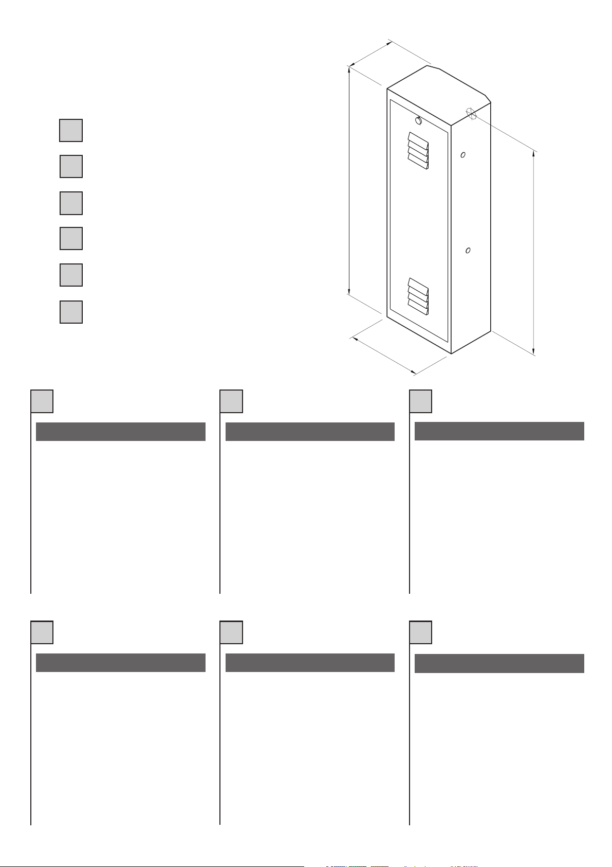
MISURE D’INGOMBRO
F
MESURES D’ENCOMBREMENT
MEDIDAS MAXIMAS EXTERNAS
E
235
1073
OVERALL MEASUREMENTS
GB
AUSSENABMESSUNGEN
D
MAATSCHETS
NL
I
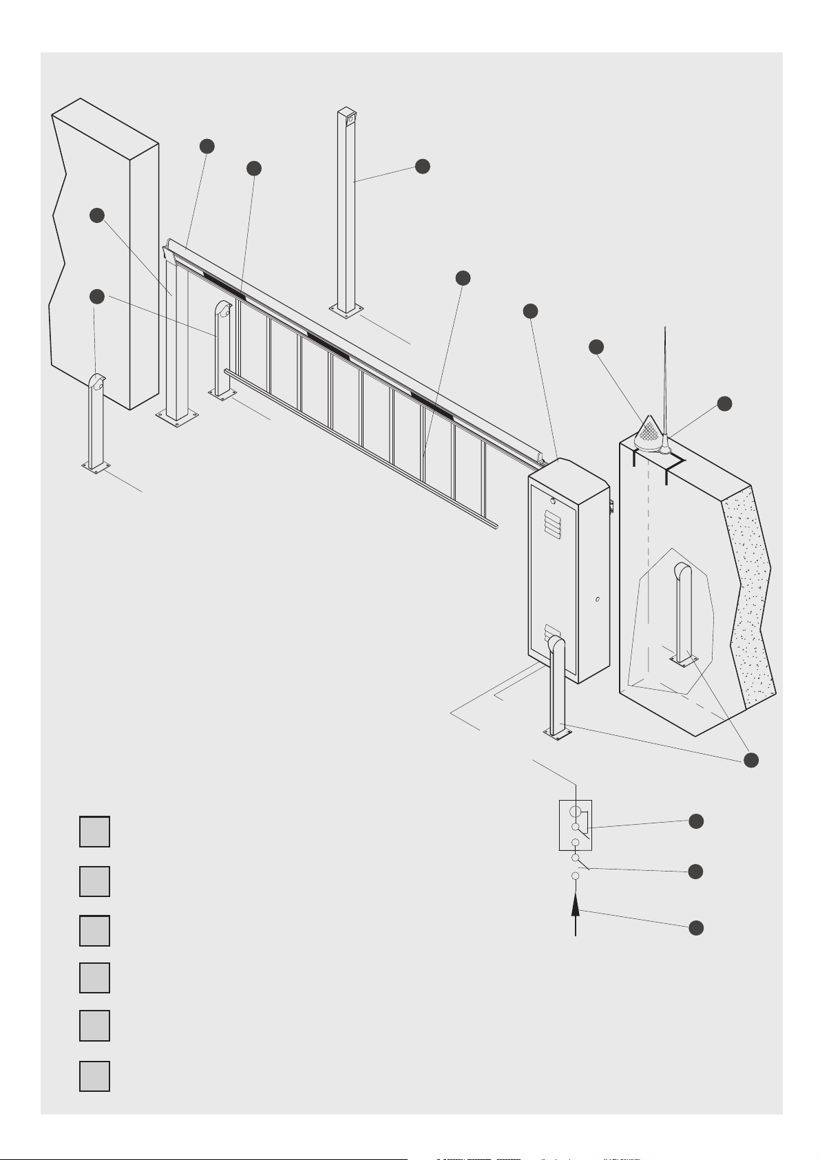
QUADRO D’ASSIEME
1) Fotocellule
2) Appoggio fisso
3) Asta in alluminio
4) Losanghe catarifrangenti
5) Selettore a chiave
6) Siepe
7) BR-6
8) Lampeggiatore
9) Antenna
10) Interruttore differenziale
11) Interruttore generale
12) Linea di alimentazione
350
F E
TABLEAU D’ENSEMBLE
1) Photocellule
2) Appui fixe
3) Barre en aluminium
4) Losanges catadioptriques
5) Sélecteur à clé
6) Epi
7) BR-6
8) Clignotant
9) Antenne
10) Interrupteur différentiel
11) Interrupteur général
12) Ligne d’alimentation
950
CUADRO DEL CONJUNTO
1) Fotocélula
2) Apoyo fijo
3) Asta de aluminio
4) Rombos catafaros
5) Selector a llave
6) Seto
7) BR-6
8) Intermitente
9) Antena
10) Interruptor diferencial
11) Interruptor general
12) Línea de alimentación
GB
D NL
GENERAL ASSEMBLY GESAMTANSICHT
1) Photocells
2) Fixed rest
3) Aluminium bar
4) Diamond-shape reflectors
5) Key selector
6) Fence frame
7) BR-6
8) Blinking light
9) Antenna
10) Differential switch
11) On/off switch
12) Power line
4
1) Photozellen (Lichtschranke)
2) Feste Auflage
3) Aluminiumstange
4) Rautenförmige Rückstrahler
5) Schlüsselwahlschalter
6) Flechtzaun
7) BR-6
8) Blinklicht
9) Antenne
10) Differentialschalter
11) Hauptschalter
12) Zufuhrlinie
OVERZICHTSTEKENING
1) Fotocellen
2) Vaste steun
3) Aluminium slagboom
4) Ruitvormige reflectoren
5) Sleutelschakelaar
6) Afrasteringsconstructie
7) BR-6
8) Knipperlicht
9) Antenne
10) Aardlekschakelaar
11) Hoofdschakelaar
12) Stroomtoevoerleiding
Page 5
3
4
2
1
5
6
7
2X1
2X1
2X1
8
9
2X1.5
RG 58
2X1
2X1
3X1.5
230V
1
I
F
E
GB
D
NL
QUADRO D’ASSIEME
TABLEAU D’ENSEMBLE
CUADRO DEL CONJUNTO
GENERAL ASSEMBLY
GESAMTANSICHT
OVERZICHTSTEKENING
10
11
12
Fig. 1 / Abb. 1
5
Page 6

I F E
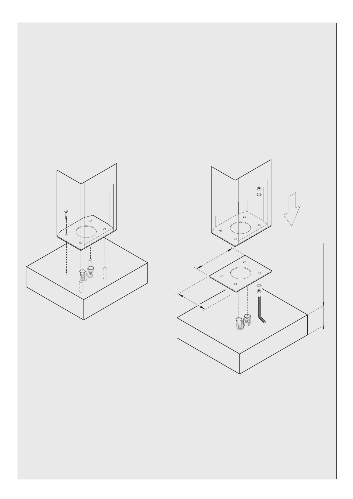
VERIFICHE PRELIMINARI
ED INSTALLAZIONEA TERRA
DELLA CONTROPIASTRA
Prima di passare all installazione vera e propria,
si consiglia di verificare che la sede di installo
della barriera sia solida ed appropriata e le permetta un esercizio corretto.
Se la BR-6 poggia su un solido basamento in
cemento, può esserefissata direttamente al suolo con 4 tasselli ad espansione D.12 (fig.2), oppure ilfissaggio può essere fatto conl ausilio della piastra. In questo caso agire nel seguente
modo:
1) Eseguire uno scavo di fondazione, tenendo
conto delle misure della piastra di fondazione.
2) Alloggiare nelloscavo le canalinedi adduzione
dei cavidi alimentazione e di collegamentoesterno.
3) Eseguire il montaggio piastra-zanche(Fig.3).
4) Annegare nelcalcestruzzo lecanaline ela piastra di fondazione e controllarne l orizzontalità.
5) Svitarei dadi dalle 4 zanchedopo che ilcalcestruzzo si sia solidificato.
6)Alloggiare sullapiastra la BR-6fissandolacon
le 4 rondelle ed i 4 dadi in dotazione.
CONTROLES PRELIMINAIRES
ET INSTALLATIONAU SOL
DE LA CONTRE-PLAQUE
Il estconseillé, avant de commencer l installation
en elle-même, de contrôler que l emplacement
réservé à labarrière soitsolide, approprié, etqu il
consente un fonctionnement correct.
Si laBR-6 repose sur unebase solide enciment,
elle peut être fixée directement au sol avec 4 vis
Tamponnées Diam.12 (fig.2) ou la fixation peut
être effectuéeà l aide de la plaque. Dans ce caslà, procéder comme suit:
1) Creuser les fondations en tenant compte des
mesures de la plaque de fondation.
2) Installer dans le trou les tuyaux d adduction
des câbles d alimentation et de raccordement
externe.
3) Exécuter le montage plaque-boulons de
serrement à crans (Fig.3).
4) Noyerdans le bétonles tuyaux et la plaque de
fondation en en contrôlant l horizontalité.
5) Dévisser les écrous des 4 boulons de
serrement à crans après que le béton se soit
Solidifié.
6) Installerla BR-6 sur la plaque en la fixantavec
les 4 rondelles et les 4 écrous en dotation.
VERIFICACIONES PRELIMINARES
E INSTALACION DESCARGAA
TIERRA DE LA CONTRAPLANCHA
Antes de pasar a la instalación efectiva, se
aconseja de controlar que el lugar donde se
Instalará la barrera sea sólido, adecuado y le
permita un ejercicio correcto.
Si BR-6 se apoya sobre una sólida base de cemento, se puede fijar directamente al suelo con
4 bulones expansibles D.12 (fig.2), o sino, la
fijación se puede realizar con la ayuda de la
plancha. Eneste caso actuar del siguientemodo:
1) Haceruna excavaciónde basamento,teniendo
en cuenta de la plancha de basamento.
2) Colocar en la excavación los canales de
aducción de los cables de alimentación y de
conexión externa
3) Realizarel montaje plancha-bulones de anclaje
(Fig.3).
4) Introduciren el cementoarmado loscanales y
la plancha de basamento y controlar su
horizontalidad.
5) Desatornillar las tuercas de los 4 bulones de
anclaje después que el cemento se haya
solidificado.
6) Colocar BR-6 sobre la plancha, fijándola con
las 4 arandelas y las 4 tuercas que vienen conel
aparato.
GB
PRELIMINARY CHECKS AND
INSTALLATION OF BASE
PLATE IN THE GROUND
Before installing, it is advisable to check that the
ground wherethe barrier isto be installedis solid
and suitable so that correct operation is not
compromised.
If the BR-6 rests on a solid cement base, it may
fixed directly to the ground with 4 screw anchors
dia.12 (fig.2) otherwise fixing may bedone using
the plate. In this case, proceed as follows:
1) Dig a foundation hole, according to the
measurements of the foundation plate.
2) Place ducts in the hole for the supply and
external connection cables to pass through.
3) Assemble the plate-rag bolts (fig. 3).
4) Bury the ducts and foundation plate in the
cement and check that they are horizontal.
5) Unscrewthe nuts from the 4 rag bolts after the
cement has set.
6) Position the BR-6 on the plate, fixing it with
the 4 washers and 4 nuts provided.
D NL
VORBEREITENDE
ÜBERPRÜFUNGEN UND
ERDUNG DER GEGENPLATTE
Vor der eigentlichen Installation ist es ratsam zu
überprüfen, obder Installationssitz derSchranke
solide und geeignet ist, und einen korrekten
Betrieb ermöglicht.
Wenn die BR-6 auf einer soliden Grundlage aus
Zement aufliegt, kann eine Schwelle mit 4
Spreizdübeln Ø 12 (Abb. 2) direkt befestigt
werden, bzw. kann die Befestigung mit Hilfe der
Platte erfolgen. In diesem Fall ist wie folgt zu
verfahren:
1) Einen Aushub entsprechend den Abmessungen der Fundamentsplatte durchführen.
2) DieVersorgungsschienen der Zufuhrkabel und
der externen Anschlüsse in dem Aushub
verlegen.
3) Die Montage Platte-Anker (Abb. 3)
durchführen.
4) Die Schienen und die Fundamentsplatte indem
Zement verlegen und deren horizontale
Ausrichtung überprüfen.
5) Die Muttern der 4 Anker festschrauben,
nachdem der Zement fest geworden ist.
6) DieBR-6 auf derPlatte positionieren undunter
Zuhilfenahme der 4 mitgelieferten
Unterlegscheiben und der 4 Muttern befestigen.
CONTROLES VOORAF
EN DE MONTAGEPLAAT
OP DE GROND INSTALLEREN
Alvorens tot de eigenlijke installatie over tegaan
adviseren wij u te controleren of de plaats waar
de slagboom geïnstalleerd wordt solide en
geschikt is zodat de slagboom goed kan
functioneren.
Als de BR-6 op een solide betonnen fundering
steunt, dan kan de slagboom met 4
expansiepluggen met een diameter van 12 mm
(fig. 2) rechtstreeks aan de grond bevestigd
worden of de slagboom kan met behulp van de
plaat. In dat geval moet u als volgt te werk gaan:
1) Graaf een funderingsgeul waarbij u rekening
moet houden met de afmetingen van de
funderingsplaat.
2) Legde kabelgoten voorde voedingskabels en
de leidingen voor de externe aansluitpunten in
de geul.
3) Monteer de plaat met de ankers (fig. 3).
4) Controleer of de kabelgoten en de
funderingsplaat volledighorizontaal liggen endek
ze vervolgens met beton af.
5) Draai nadat het beton uitgehard is de moeren
vande4ankersaf.
6) Zet de BR-6 op deplaat en maak deze met de
4 meegeleverde onderlegringen en de 4 moeren
vast.
6
Page 7
344
Fig. 2 / Abb. 2
232
min. 150 mm
Fig. 3 / Abb. 3
7
Page 8
I
F E
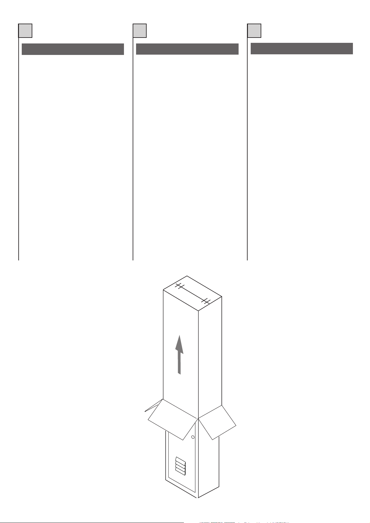
INSTALLAZIONE DELLABARRIERA
Dato il peso della barriera, la movimentazione
della stessa dovrà essere eseguita da più persone.
Lo sballaggio dovrà essere eseguito come illustrato in fig. 4.
Per il collegamento elettrico si consiglia di usare un cavo di alimentazione 3x1.5.
1) Installare la barriera a terra nei modi precedentemente descritti.
2) Fissare l’asta alla barriera
3) Portare la barriera in posizione di asta abbassata
4) Effettuare i necessari collegamenti elettrici.
5) Dare alimentazione
6) Eseguire la regolazione delle camme di
finecorsa
7) Provare il funzionamento dell’impianto
8) Effettuare le operazioni di: regolazione della frenatura, regolazione del flusso d’olio,
regolazione di forza.
9) Selezionaresulla centralina elettronica di comando le modalità di funzionamento desiderate.
INSTALLATION DE LA BARRIERE
Vu le poids de la barrière, celle-ci devra être
déplacée par plusieurs personnes. Le
déballage sera exécuté comme indiqué à la
fig.4.
Il estconseillé, pour lebranchement électrique,
d’utiliser un câble d’alimentation 3x1,5.
1) Installer la barrière au sol comme décrit
précédemment.
2) Fixer la barre à la barrière.
3) Placer la barrière en position de barre
baissée.
4) Effectuer les branchements électriques
nécessaires.
5) Brancher le courant.
6) Régler les cames de fin de course.
7) Faire un essai de fonctionnement.
8) Effectuer les opérations de: réglage du
freinage, réglage du flux d’huile, réglage de
force.
9) Sélectionner sur la centrale électronique de
commande les modalités de fonctionnement
désirées.
INSTALACION DE LA BARRERA
Debido alpeso de labarrera, lamovimentación
de la misma tiene que realizarse por varias
personas.
El desembalajedebe realizarse comoilustrado
en la fig. 4.
Para la conexión eléctrica se aconseja usar
un cable de alimentación 3x1.5.
1) Instalar la barrera a tierra en las formas anteriormente descriptas.
2) Fijar el asta a la barrera
3) Llevar la barrera a la posición de asta baja.
4) Efectuar las conexiones eléctricas
necesarias.
5) Dar alimentación
6) Efectuar la regulación de las levas de tope
de recorrido.
7) Probar el funcionamiento de la instalación
8) Efectuar las operaciones de regulación del
frenado, regulación del flujo de aceite,
regulación de fuerza.
9) Seleccionar en el tablero electrónico de
mando las formas de funcionamiento
deseadas.
Fig. 4 / Abb. 4
8
Page 9

GB D NL
INSTALLATION OF THE BARRIER INSTALLATION DER SCHRANKE DE SLAGBOOM INSTALLEREN
Given the weight of the barrier, it should be
handled by several persons.
Unpack as shown in fig. 4.
A 3 x 1.5 power supply cable is recommended
for electrical connection.
1) Install the barrier as described above.
2) Fix the bar to the barrier.
3) Put the barrier to the “bar down” position.
4) Make the necessary electrical connections.
5) Turn on the power supply.
6) Adjust the limit stop cams.
7) Test operation of the installation.
8) Carry out the following: adjustment of
braking, adjustment of oil flow, adjustment of
force.
9) Select the required operating modes on the
electronic control unit.
Aufgrund des Gewichtes der Schranke ist die
Versetzung derselben vonmehreren Personen
durchzuführen.
Das Auspacken ist wie in Abbildung 4
dargestellt durchzuführen.
Für den Elektroanschluß ist es ratsam, ein
Stromzufuhrkabel von 3 x 1.5 zu verwenden.
1) Die Schranke am Boden auf die vorab
beschriebene Weise installieren.
2) Die Stange an der Schranke befestigen.
3) Die Schranke in die abgesenkte Position
bringen.
4) Die notwendigen Elektroanschlüsse
ausführen.
5) Die Stromversorgung einschalten.
6) Die Einstellung der Endanschlagsnocken
durchführen.
7) Den Betrieb der Anlage ausprobieren.
8) Folgende Operationen durchführen:
Einstellung der Abbremsung, Einstellung des
Ölflusses, Einstellung der Hubkraft.
9) Auf der elektronischen Steuerzentrale die
gewünschte Betriebsart auswählen.
Met het oog op het gewicht van de slagboom
moet de slagboom door meerdere personen
verplaatst worden.
Haal de slagboom uit de verpakking zoals
afgebeeld op fig. 4.
Om de elektrische aansluiting tot stand te
brengen adviseren wij u gebruik te maken van
een elektrisch snoer 3x1.5
1) Installeer de slagboom op de grond op de
hiervoor beschreven manier.
2) Maak de slagboom vast.
3) Zet de slagboom in een dusdanige stand
dat de slagboom naar beneden is.
4) Breng de nodige elektrische aansluitingen
tot stand.
5) Schakel de stroomtoevoer in.
6) Stel de aanslagnokken af.
7) Test de werking van de installatie.
8) Stel nu het volgende af: de remmende
werking, de doorstroomhoeveelheid van de
olie, de kracht.
9) Stel de gewenste werking op de
elektronische bedieningseenheid in.
Fig. 4 / Abb. 4
9
Page 10

I
F E
INSTALLAZIONE SINISTRA
La BR-6 vienefornita perun utilizzo normalmente destroed in posizionedi asta alzata, cosicché
la molladi contrappeso interna non risultiessere
caricata. Con“uso normalmente destro” si intende armadietto montato a destra della luce di passaggio. (Vistadall’interno). (fig.1)
Per un utilizzo della barriera sinistro procedere
nel seguentemodo:
1) Sbloccare la centralina idraulica agendo sull’apposita manopola.(fig.5)
2) Allentare il carico della molla portandolo azero
agendo sullavite di registromolla. (fig.6)
3) Sganciarela molla dall’attacco inferiore. (fig.7)
4) Estrarre il gruppo molla dalla barriera e appoggiarlo aterra. (fig.8)
5)Allentare il controdado e liberare il gruppo leva
comando. (fig.9)
6) Svitare la vite su leva comando. (fig.10)
7) Estrarre la leva comando dall’alberoscanalato
e ruotarla di180° circa reinserendolasull’albero.
(fig.11)[Per estrarre la leva comando servirsi della
vite indotazione e usarlada estrattore]
8) Risistemare la vite su leva comando serrandola conforza.
9) Fissare il gruppo leva comando al bilancino
serrando col controdado. (fig.12)
[Invertendo i leveraggi della barriera porteremo
l’asta adessere abbassata].
10) Posizionarsi posteriormente alla barriera e
verificare chela rotazione dellapiastra con albero crei un angolo di 90° (fig.13); se necessario
ricontrollare la posizione della leva comando o,
per piccoli aggiustamenti, agire sul braccio comando asta.(fig.14).
11)Assicurarsi chela barriera sia in posizione di
asta alzata
12) Installare il gruppo molla sul bilancino, agganciare lamolla all’attacco inferiore(fig.15), ed
agire sullavite registro mollacaricandola quanto
basta pergarantire un sufficiente aiuto alla movimentazione dell’asta.Per un bilanciamento corretto porre l’asta a 45° ed agire sulla vite di registro fino ad equilibrarne il peso.
13) Bloccarela centralina idraulica
14) Invertire i 2 tubi dell’olio del distributore
(fig.16). Se necessario eseguire lo spurgo del
martinetto.
15) Invertire le fasi dei finecorsa: apertura e chiusura. (vedi“morsettiere” T100)
Per verificare che la regolazione della molla sia
sufficiente, e che l’asta nel movimento sviluppi
90°, si installi l’asta alla barriera e le si facciano
fare alcunemanovre.
INSTALLATION GAUCHE
La BR-6 est normalement fournie pourun usage
“droit” eten position de barre levéede façon àce
que leressort de contre-poidsinterne nesoit pas
bandé. L’expression “usagenormal droit”indique
que l’armoire est montée à droite de l’ouverture
de passage.(Vue del’intérieur). (fig.1).
Pour une usage “gauche” de la barrière, procéder
comme suit:
1) Débloquerla centrale hydrauliqueen agissant
sur la poignée prévue à cet effet (fig.5).
2) Relâcher la charge du ressort et la porter à
zéro en agissant sur la vis de réglage ressort
(fig.6).
3) Décrocher le ressort de la fixation inférieure
(fig.7).
4) Extraire le groupe ressort de la barrière et
l’appuyer parterre (fig.8).
5) Dévisser le contre-écrou et libérer le groupe
levier decommande (fig.9).
6) Dévisserla vis du levier de commande (fig.10).
7) Extraire le levier de commande de l’arbre
cannelé etle faire tourner de 180 environ enle
fixant de nouveau sur l’arbre. (fig.11). [Pour
extraire le levier de commande, utiliser la vis en
dotation ets’en servir comme extracteur].
8)Revisserlavissurlelevierdecommandeen
la serrant fortement.
9) Fixer le groupe levier de commande au
palonnier enserrant avecle contre-écrou (fig.12).
[Le fait d’invertir les systèmes de levage de la
barrière détermine uneposition baissée de labarre].
10) Se placer derrière la barrière et vérifier que
la rotationde la plaque avec l’arbredétermine un
angle de90 (fig.13); si nécessaire,contrôler de
nouveau la position du levier de commande ou,
par de petits réglages, agir sur le bras de
commande de la barre. (fig. 14).
11) S’assurer que la barrière soit en position de
barre levée.
12) Installer le groupe ressort sur le palonnier,
accrocher leressort à la fixation inférieure (fig.15)
et agir sur la vis deréglage du ressort de manière
à ce que celui-ci puisse garantir une aide
suffisante à l’actionnement de la barre. Pour un
équilibrage correct placer la barre à 45 et agir
sur la vis de réglage jusqu’àen équilibrer lepoids.
13) Bloquerla centrale hydraulique.
14) Invertir les deuxtubes de l’huile dudistributeur
(fig.16). Sinécessaire purger levérin.
15)Invertir lesphases des finsde course: ouverture et fermeture (voir “barrettes de connexion”
T100).
Pour s’assurer que le réglage du ressort est
suffisant etque la barre en s’ouvrant présente un
angle de 90 , installer la barre surla barrière et
exécuter quelquesmanoeuvres.
INSTALACION IZQUIERDA
La BR-6 se entrega para un uso normalmente
hacia la derecha y en posición de asta levantada,
de este modo el resorte de contrapeso interno
no esté cargado. El “uso normalmente hacia la
derecha” significa armario armado a la derecha
de la luz de paso. (Vista desde el interior). (fig.
1).
Para un uso hacia la izquierda de la barrera
realizar losiguiente:
1) Desbloquear el tablero hidráulico por medio
del correspondiente botón. (fig.5).
2) Aflojar la carga del resorte llevándolo a cero
en el tornillo de registro resorte. (fig.6).
3) Desenganchar el resorte juntura inferior. (fig.7).
4) Extraer el grupo resorte de la barreray apoyarlo
en el suelo. (fig. 8)
5)Aflojar lacontratuerca y soltar el grupo palanca
mando. (fig.9)
6) Desatornillar el tornillo en la palanca mando.
(fig.10)
7) Extraerla palanca mandodel árbol acanalado
y girarla de aprox. 180°volvièndolaa colocaren
el árbol.(fig. 11)[Para extraer lapalanca mandos
usar los tornillos, que vienen con el aparato, y
usarlos comoextractor].
8) Volver a colocar el tornillo en la palanca de
mando ajustándolocon fuerza.
9) Fijar el grupo palanca mando al balancín
apretando conla contratuerca. (fig.12)
10) Posicionarse posteriormente a la barrera y
controlar que la rotación de laplancha con el árbol
forme un ángulo de 90° (fig.13); si es necesario
volver acontrolar la posiciónde la palancamando o, para pequeños ajustes, actuar sobre el
brazo mandoasta. (fig.14).
11)Verificar que labarrera estéen posición asta
levantada.
12) Instalar el grupo resorte en el balancín,
enganchar elresorte a lajuntura inferior (fig.15),
y actuaren el tornillo registro resorte cargándolo
lo necesariopara garantizar una suficiente ayuda
al movimiento del asta. Para un balanceo correcto
poner el asta a 45° y actuar sobre el tornillo de
registro hastaequilibrar el peso.
13) Bloquearel tablero demandos hidráulico.
14) Invertir los 2 tubos del aceite del distribuidor
(fig. 16). Si es necesario realizar la expurgación
del gato.
15) Invertir las fases de los topes de recorrido:
abertura ycierre. (ver “tableros de bornes” T100).
Para verificar que la regulación del resorte sea
suficiente, y que el asta en el movimiento
desarrolle 90°. hayque instalar el astaa la barrera
y hacerlehacer algunas maniobras.
10
Page 11
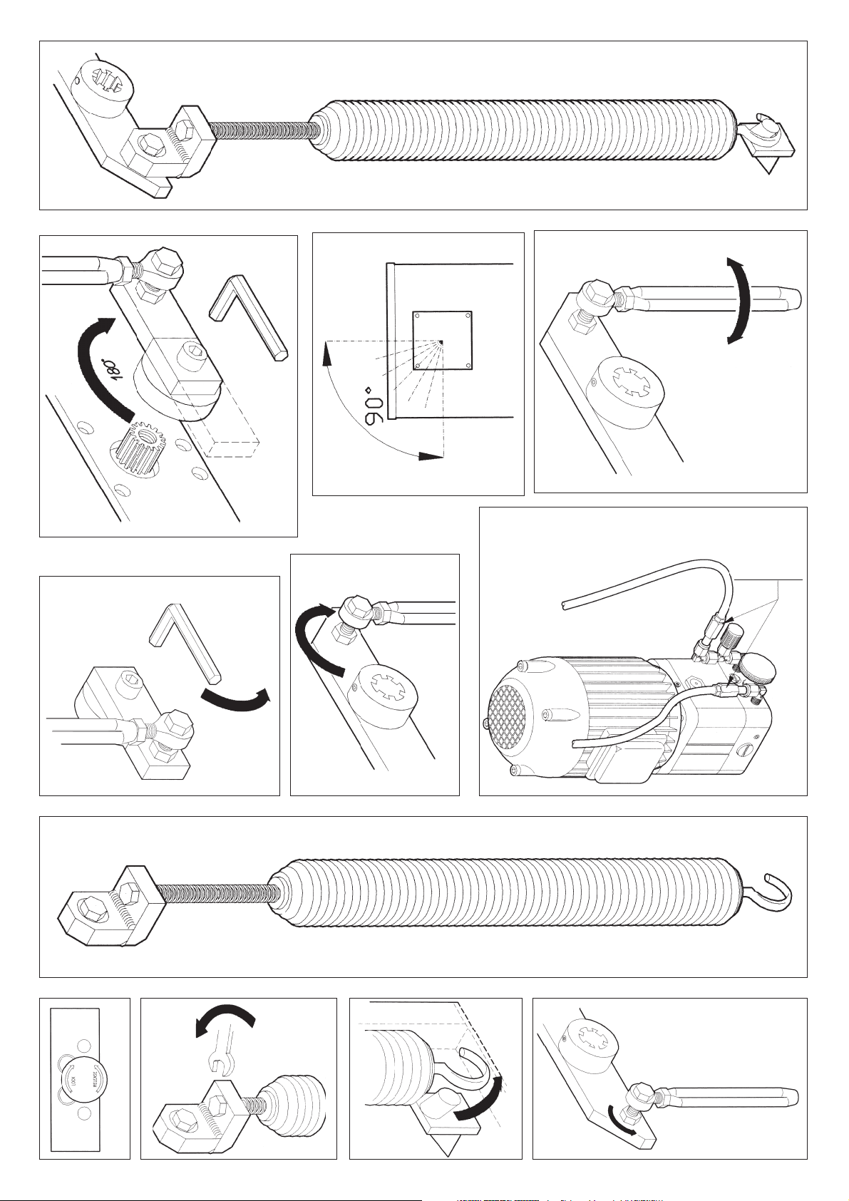
Fig. 13
Fig. 15
Fig. 14
Fig. 10
Fig. 11
INVERTIRE
INVERTIR
INVERTIR
INVERT
UMKEHREN
OMKEREN
Fig. 12
Fig. 16
Fig. 8
Fig. 5
Fig. 6
Fig. 7
Fig. 9
11
Page 12

GB D NL
LEFT-HAND INSTALLATION INSTALLATION LINKS
The BR-6comes supplied forright-hand use andin
the “bar-up” position; the internal counterweight
spring isconsequently not loaded.The expression
“right-hand use” means that the box is assembled
to the right of the aperture (seen from inside). (fig.
1).
For left-hand use ofthe barrier, proceed as follows:
1) Release the hydraulic power unit by means of
the relative knob. (fig. 5).
2) Fully release theload on thespring by meansof
the spring adjusting screw.
3) Unhook the spring from the bottom connection.
(fig. 7).
4) Remove the springunit from thebarrier and rest
it on the ground (fig. 8).
5) Loosen the lock nut and free the control lever
unit. (fig. 9).
6) Loosen the screw on the control lever. (fig. 10).
7) Remove the control leverfrom the splined shaft
and turn it about 180°, then insert it onto the shaft
again. (fig. 11). [To remove the control lever, use
the screw provided as an extractor].
8) Replacethe screw on the control lever andtighten
securely.
9) Fix the control lever unit to the rocker arm,
securing with the lock nut. (fig. 12).
10) Standbehind the barrier and checkthat rotation
of the plate with the shaft creates an angle of 90°
(fig. 13); if necessary check the position of the
control lever again or, for small adjustments, use
the bar control arm. (fig. 14).
11) Make sure that the barrier is in the “bar up”
position.
12) Install the spring unit on the rocker arm, hook
the springonto the bottomconnection (fig. 15) and
turn the springadjusting screw just enough to ensure
bar movement. For correct balancing, put the bar
to 45° and turn the adjusting screw until its weight
is balanced.
13) Lock the hydraulic power unit.
14) Invert the 2 distributor oil pipes (fig. 16). If
necessary bleed the jack.
15) Invert limit-switch phases: opening and closing.
(see T100 “terminal board”).
To check that the spring has been regulated
correctly and that the bar will reach 90° in its
movement, installthe bar ontothe barrier andoperate the installation a few times.
12
Die BR-6wird für dienormalerweise üblicherechte
Verwendung und in der Position mit angehobener
Stange geliefert, d.h. daß die interne
Gegengewichtsfeder nicht gespannt ist. Unter der
„normalerweise rechten“Anwendung versteht sich,
daß der Schrank rechts vom Durchgang montiert
ist (von der Innenseite aus gesehen). (Abb. 1).
Für dieAnwendung der linken Schranke ist wiefolgt
zu verfahren:
1) Diehydraulische Zentrale durchBetätigung des
entsprechenden Drehknopfesentriegeln (Abb. 5);
2) Die Federspannung lockern, indem die
Federspannungsschraube auf Null gebracht wird
(Abb. 6);
3) Die Feder aus dem unteren Einsatz aushaken
(Abb. 7);
4) Die Federgruppe aus der Schranke herausnehmen und aufden Boden legen (Abb. 8);
5) Die Gegenmutter lockern und die
Steuerhebelgruppe befreien (Abb.9);
6) Die Schraube auf dem Steuerhebel
ausschrauben (Abb.10);
7) Den Steuerhebel aus der Keilwelle herausnehmen, um ca. 180° drehen, und wieder in die Welle
einsetzen (Abb. 11). (Um den Steuerhebel
herauszunehmen, ist sich der mitgelieferten
Schraube alsAuszieher zu bedienen).
8) Die Schraube wieder auf dem Steuerhebel
einsetzen und mit Kraft festziehen.
9) Die Steuerhebelgruppe am Auspendler
befestigen und mit der Gegenmutter festziehen
(Abb. 12).
(Durch Umkehrender Hebelsysteme derSchranke
wird dieStange abgesenkt).
10) Sich hinter die Schranke stellenund überprüfen,
daß die Drehung der Platte mit der Welle einen
Winkel von 90° bildet (Abb. 13); falls notwendig,
die Position des Steuerhebels erneut kontrollieren
bzw. kleinere Justierungen auf dem
Stangensteuerarm ausführen (Abb. 14);
11) Sicherstellen, daß sich die Schranke in der
angehobenen Position befindet;
12) Die Federgruppe auf dem Auspendler
installieren, dieFeder in den unterenEinsatz (Abb.
15) einhaken, und die Federstellschraube für die
notwendige Federspannung betätigen, um eine
ausreichende Hilfe bei der Bewegung der Stange
zu gewährleisten. Für eine korrekte
Ausbalancierung ist die Stangeauf 45° zubringen
und dieStellschraube bis zurAusbalancierung des
Gewichtes zu betätigen.
13) Die hydraulische Zentrale blockieren.
14) Die 2 Rohre des Verteileröls (Abb. 16)
umkehren. Falls notwendig die Entlüftung des
Hebebocks durchführen.
15) Die Phasen des Endanschlags umkehren:
Öffnung und Schließung (siehe „Klemmenleisten“
T100).
Um zu überprüfen, daß die Einstellung der Feder
ausreichend ist, und daß die Stange bei der
Bewegung 90° ausführt, wird die Stange auf der
Schranke installiert und einige Manöver
durchgeführt.
DE SLAGBOOMLINKS INSTALLEREN
De BR-6 wordt standaard voor rechts gebruik
geleverd en met de slagboom in omhoogstaande
stand zodatde tegengewichtveer nietbelast wordt.
Met “standaard rechts gebruik” wordt bedoeld dat
de schakelkast aan de rechterkant van de
openingsdoorgang is gemonteerd (van binnenuit
gezien) (zie fig.1).
Om hetgebruik aande linkerkant vande slagboom
mogelijk te maken moet u als volgt te werk gaan:
1) Koppel de hydraulische besturingseenheid met
behulp van de betreffende knop los. (fig. 5)
2) Verminder de belasting van de veer door deze
op nul te stellen door aan de stelschroef van de
veer te draaien. (fig. 6)
3) Maak de veer van de onderste bevestiging los.
(fig. 7)
4) Haalde veereenheid vande slagboom afen leg
deze op degrond. (fig. 8)
5) Draai de contramoer los en maak de
bedieningshendeleenheid los.(fig. 9)
6) Draai de schroef op de bedieningshendel los.
(fig. 10)
7) Trek de bedieningshendel uit de as en draai de
hendel ongeveer180° en doede hendel weerin de
as. (fig. 11) [Om de bedieningshendel eruit te
trekken moet u gebruik maken van de
meegeleverde schroef en deze als trekker laten
fungeren].
8) Doede schroef weerop de bedieningshendelen
draai de schroef krachtig aan.
9) Maak de bedieningshendeleenheid aan de
tuimelaar vast en borg deze met de contramoer.
(fig. 12)
[Als de hendelsystemen van de slagboom
omgekeerd wordendan moet deslagboom omlaag
gedaan zijn].
10) Ga achter de slagboom staan en controleer of
de draaibewegingvan de plaatmet de aseen hoek
van 90°vormt (fig.13); indien nodigmoet u de stand
van de bedieningshendel opnieuw controleren of
de bedieningsarm van de slagboom steeds een
beetje verschuiven. (fig.14)
11) Verzeker u ervan dat de slagboom in de
omhoogstaande standstaat.
12) Installeer de veereenheid op detuimelaar, maak
de veer aan de onderste bevestiging vast (fig. 15)
en draaiaan de stelschroefvan de veerom de veer
zoveel te spannen als nodig is om de beweging
van de slagboom in voldoende mate te
ondersteunen. Om ervoor te zorgen dat de
slagboom op de juiste manier in balans is moet u
de slagboomop 45° plaatsen en aan de stelschroef
draaien totdat het gewicht ervan in balans is.
13) Vergrendel dehydraulische besturingseenheid.
14) Verwissel de beide olieleidingen van de
distributeur (fig. 16). Indien nodig moet de vijzel
ontlucht worden.
15) Verwissel de fases van de eindaanslagen:
openen en sluiten (zie de paragraaf
“klemmenstroken” in de T100 handleiding).
Om te controleren of de afstelling van de veer
voldoende isen de slagboom 90° kan draaien moet
de slagboom gemonteerd worden en moet u de
slagboom enkele manoeuvres laten maken.
Page 13

Fig. 13
Fig. 15
Fig. 14
Fig. 10
Fig. 11
INVERTIRE
INVERTIR
INVERTIR
INVERT
UMKEHREN
OMKEREN
Fig. 12
Fig. 16
Fig. 8
Fig. 5
Fig. 6
Fig. 7
Fig. 9
13
Page 14

I
F E
SPURGO DEL MARTINETTO PURGE DU VERIN
Ogni volta si renda necessaria la sostituzione
o il rabbocco dell’olio eseguire l’operazione di
spurgo. Agire come segue:
1) Estrarre la leva motore (fig. 11)
2) Impostare sulla centralina elettronica il tempo
massimo di lavoro, in modo che la pompa continui il suo funzionamento fino a che termini la rotazione dell’albero scanalato del martinetto.
)
Azionare la centralina elettronica di comando.
3
4) Spurgare l’aria aprendo una delle due valvole fino a che esca solo olio (part.1 fig.17).
5) Chiudere la valvola e ripeterne l’operazione
con l’altra.
Il est nécessaire de purger le vérin après
chaque ajout ou remplacement de l’huile.
Procéder comme suit:
1) Extraire le levier moteur (fig. 11)
2) Programmer le temps maximum de
fonctionnement sur la centrale électrique de
manière à ce que la pompe continue de
fonctionner jusqu’àce que larotation de l’arbre
cannelé du vérin soit terminée.
3) Actionner la centrale électronique de
commande.
4) Purger l’air en ouvrant une des deux valves
et cejusqu’à ce quene sorte plusque de l’huile
(dét.1 fig.17).
5) Refermer la première valve et répéter
l’opération avec l’autre.
EXPURGACION DEL GATO
Cada vez que sea necesaria la sustitución o
el llenado de aceite, realizar la operación de
expurgación, del siguiente modo:
1) Extraer la palanca motor (fig 11)
2) Plantearen la centralita electrónica el tiempo
máximo de trabajo, de manera que la bomba
continœe su funcionamiento, hasta que termine larotación del árbol estriado del martinete.
3) Accionar el tablero electrónico de mando.
4) Expurgarel aire abriendo una de las válvulas
hasta que salga todo el aceite (part.1 fig.17).
5) Cerrar la válvula y repetir la operación con
la otra.
GB
D NL
BLEEDING THE JACK ENTLÜFTUNG DES HEBEBOCKS
Whenever it is necessary to change or top up
the oil, bleed the jack as follows:
1) Pull out the motor lever (fig. 11)
2) Set the maximum working time on the
electronic control unit so that the pump
continues operating until the spline shaft of
the jack finishes rotating.
3) Switch on the electronic control unit.
4) Bleed off the air by opening one of the two
valves until only oil comes out (det. 1 fig. 17).
5) Close the valve and repeat the operation
with the other.
Bei jedemÖlwechsel bzw. Ölnachfüllen ist eine
Entlüftung durchzuführen, wobei wie folgt zu
verfahren ist:
1) Den Motorhebel herausnehmen (Abb. 11)
2) Auf der elektronischen Steuereinheit die
maximale Betriebszeit eingeben, so daß die
Pumpe ihren Betrieb solange fortsetzt, bis die
Drehung der Windenkeilwelle beendet ist.
3) Die elektronische Steuerzentrale
einschalten.
4) Die Luft durch Öffnen einer der beiden
Ventile entweichen lassen bis aus diesem
lediglich Öl ausläuft (Detail 1, Abb 17);
5) Das Ventil schließen und die Operation mit
dem anderen Ventil wiederholen.
DE VIJZEL ONTLUCHTEN
Telkens als de olie ververst of bijgevuld moet
worden moet u de vijzel ontluchten. Ga in dat
geval als volgt te werk:
1)Trek de motorhendel eruit (fig. 11)
2) Stel op de elektronische besturingskast de
maximum werktijd in zodat de pomp blijft
doorwerken totdat de gegroefde as van de
cilinder ophoudt met draaien.
3) Stel de elektronische bedieningseenheid in
werking.
4) Ontlucht de vijzel door één van de beide
kleppen te openen totdat er alleen olie uitkomt
(detail 1, fig. 17).
5) Doe de klep weer dicht en doe hetzelfde bij
de andere klep.
14
Page 15

I
F E
REGOLAZIONE DELLA FRENATA REGLAGE DU FREINAGE
Per la regolazione della frenata del martinetto
in apertura ed in chiusura, agire sulle due manopole (part.2 fig.17)
Per ridurre la velocità in arrivo, ruotare le valvole nel senso indicato fino a quando la fase
di frenatura cominci ad agire circa 10° prima
che l’asta arrivi a fine corsa.
GB
Pour le réglage du freinage du vérin en ouverture eten fermeture, agir sur les deux poignées
(dét.2 fig.17).
Pour réduire la vitesse à l’arrivée, tourner la
valve dans le sens indiqué jusqu’à obtenir un
début de freinage environ 10° avant que la
barre n’arrive en fin de course.
D NL
BRAKING ADJUSTMENT BREMSEINSTELLUNG
Use the two knobs (det. 2 fig. 17) to adjust
braking of the jack in opening and closing
operations.
To reduce the arrival speed, turn the valves in
the indicated direction until braking starts at
about 10° before the bar arrives at the end of
its stroke.
Für die Bremseinstellung des Hebebocks
während derÖffnungs- und Schließphase sind
die beiden Drehknöpfe zu betätigen (Detail 2,
Abb. 17).
Um die Ankunftsgeschwindigkeit zu
reduzieren, die Ventile in der angegebenen
Richtung drehen bis die Bremsphase auf
ungefähr 10° auslöst, bevor die Stange am
Endanschlag ankommt.
REGULACION DE LA FRENADA
Para la regulación de la frenada del gato en
abertura ycierre, actuar enlos botones (part.2
fig.17).
Para reducir la velocidad en la llegada, girar
las válvulas en el sentido indicado hasta
cuando la fase de frenado comience a actuar,
aprox. 10° antes que el asta llegue al final del
recorrido.
DE REMMENDE WERKING
VAN DE VIJZEL AFSTELLEN
Om deremmende werking vande vijzel tijdens
de open- en de dichtgaande beweging af te
stellen moet u gebruik maken van de twee
knoppen (detail 2, fig. 17).
Om de snelheid waarmee de slagboom
omlaag gaat te verlagen moet u de kleppen in
de aangegeven richting draaien totdat de
remmende werking ongeveer 10° voordat de
slagboom tegen de eindaanslag aankomt
begint.
2
+
-
1
Fig. 17 /Abb. 17
15
Page 16

I
F E
REGOLATORE DI FLUSSO REGULATEUR DE FLUX
Ha la funzione di stabilizzare il flusso dell’olio
andando ad agire sulla portata, evitando così
che l’asta sobbalzi nel movimento
La regolazione del flusso viene eseguita con
la barriera in funzione. Agire sulla manopola
come indicato in fig.18.
GB
Sa fonction est de stabiliser le flux d’huile en
agissant sur le débit et ce de manière à éviter
des soubresauts dans le mouvement.
Le réglage du flux doit être exécuté alors que
la barrière fonctionne. Agir sur la poignée
comme indiqué à la fig.18.
D NL
FLOW REGULATOR FLUSSREGLER
REGULADOR DE FLUJO
Tiene la función de estabilizarel flujo del aceite
actuando en el flujo, evitando, de este modo
que el asta salte en el movimiento.
La regulacióndel flujo serealiza con labarrera
en función.Actuar en el botón, como indicado
en la fig. 18.
OLIEDOORSTROOMREGELAAR
The flow regulator has the function of
stabilising the oil flow by acting on the flow
rate so that the bar does notjolt when moving.
Flow regulation is carried out with the barrier
in operation. Use the knob as shown in fig.
18.
Dieser hat die Funktion, den Ölfluss durch
Beeinflussung der Leistung zu stabilisieren,
wodurch vermieden wird, daß die Stange
während der Bewegung aufschlägt.
Die Flussregelung wird während des
Schrankenbetriebs durchgeführt. Den
Drehknopf wiein Abb. 18 dargestelltbetätigen.
VITE DISFIATO
VISDEPURGE
TORNILLOS RESPIRADERO
VENTING SCREW
ENTLÜFTUNGSSCHRAUBE
ONTLUCHTINGSSCHROEF
SPIA OLIO
VOYANT HUILE
SEÑALACEITE
OIL WINDOW
ÖLSTANDSANZEIGER
OLIEKIJKGLAS
Deze regelaar dient om de
doorstroomhoeveelheid testabiliseren door op
de hoeveelheid olie in te werken, waardoor
wordt voorkomen dat de slagboom tijdens de
beweging opspringt.
De regeling van de doorstroomhoeveelheid
vindt plaatsals de slagboom in werkingis. Druk
op de knop zoals afgebeeld op fig. 18.
16
Fig. 18 /Abb. 18
Page 17

I
F E
REGOLAZIONE FORZA REGULATEUR DE FORCE
La regolazione di forza della centralina idraulica
è data da due valvole: una di colore oro, una di
colore argento (in modo da distinguere il moto
nei due sensi). (fig.19)
La forza trasmessa dalla centralina idraulica è
direttamente proporzionale alla quantità di rotazione in senso orario della valvola.
Si consigliadi iniziare conle valvole svitatequasi
del tutto e proseguire per tentativi, tenendo presente checon minime rotazionisi ottengono ogni
volta variazionisignificative.
Le variazioni di carico devono essere verificate
con un dinamometro.
GB
Le réglage de force de la centrale
hydraulique est assuré par deux valves, une de
couleur dorée et une de couleur argentée (de
façon à distinguer le mouvement dans les deux
sens) (fig.19).
La forcetransmise par lacentrale hydraulique est
directement proportionnelle à l’importance de la
rotation, dansle sens desaiguilles d’une montre,
de la valve.
Il est conseillé de commencer avec les valves
pratiquement dévissées et de continuer par
petites tentatives en tenant compte du fait que
même les plus infimes rotations déterminent
toujours des variations significatives.
Les variations decharge doivent être contrôlées
avec un dynamomètre
D NL
ADJUSTMENT OF FORCE EINSTELLUNG DER HUBKRAFT
REGULACION FUERZA
La regulación de fuerza del tablero de mando
hidráulico está dada por dos válvulas:una de color
oro, una de color plata (con el fin de distinguir el
movimiento en los dos sentidos).(fig.19)
La fuerza transmitida por el tablero de mando
hidráulico es directamente proporcional a la
cantidad de rotación en sentido horario de la
válvula.
Se aconseja iniciar con las válvulas
desatornilladas casi del todo y continuar por
tentativos, teniendopresente que conrotaciones
mínimas se obtienen, cada vez, variaciones
significativas.
Las variaciones decarga tienen que controlarse
con un dinamómetro
DE KRACHT REGELEN
Two valves are used to adjust the force of the
hydraulic powerpack: one colouredgold and one
silver (todistinguish motion inthe two directions).
(fig. 19).
The forcetransmitted by thehydraulic power unit
is directly proportional to the amount the valve
rotates clockwise.
It is advisable to start with the valves almost
completely unscrewed and then proceed by trial
and error, bearing in mind that significant
variations are obtained with the minimum of
rotation each time.
Load variations should be checked with a
dynamometer.
Die Einstellung der Hubkraft der hydraulischen
Zentrale erfolgt durch die beiden Ventile: ein
goldfarbenes und ein silberfarbenes (um die
Bewegung derbeiden Richtungen unterscheiden
zu können) (Abb. 19).
Die von der hydraulischen Zentrale übertragene
Hubkraft ist direkt proportional zu der
Drehquantität des Ventils im Uhrzeigersinn.
Es istratsam, mit den fast vollständig gelockerten
Ventilen zu beginnen, und einige Versuche
durchzuführen, wobei zu beachten ist, daß mit
minimalen Drehungen jedes Mal bedeutende
Veränderungen erzielt werden.
Die Belastungsschwankungenmüssen mit einem
Dynamometer überprüft werden
De regeling van de hydraulische
besturingseenheid overgebrachtekracht gebeurt
door twee kleppen: één klep is goud gekleurd en
de anderzilver gekleurd (aande hand waarvan u
de beweging in de beide richtingen kunt
onderscheiden) (fig. 19).
De kracht die door de hydraulische
besturingseenheid overgebracht wordt is
rechtstreeks evenredig aan de mate waarin de
klep met de wijzers van de klok mee draait (naar
rechts).
Wij adviserenu te beginnenmet de kleppenbijna
volledig losgedraaid en de kleppen vervolgens
telkens een slag proberen te draaien, waarbij u
er rekening mee moet houden dat als u de
kleppen ook maar iets draait dit soms grote
veranderingen teweeg kan brengen.
Krachtswijzigingen moetenaan de handvan een
krachtmeter gecontroleerd worden.
Fig. 19 /Abb. 19
17
Page 18

I F E
COLLEGAMENTO ELETTRICO BRANCHEMENT ELECTRIQUE
Vedi nel manuale T100 “morsettiere”. Voir dans le manuel T100 “barrettes de
connexion”.
I F E
SOSTITUZIONE OLIO CHANGEMENT HUILE
La sostituzione dell’olio deve essere eseguita
dopo 100000 cicli (1 ciclo= apertura + chiusura) agendo nel seguente modo:
1) Portare la barriera inposizione di asta alzata.
2) Staccare il quadro di alimentazione generale dell’impianto.
3) Svitare i due fermi di fissaggio ed estrarre il
gruppo pompa (fig.16) sistemandolo in posizione orizzontale.
4) Svitare la spia dell’olio (fig.18)
5) Usando un contenitore svuotare l’olio della
centralina idraulica.
6) Sbloccare la centralina idraulica.
7) Fareeseguire un ciclo completodi apertura
e chiusura manualmente alla BR-6 e ripetere
il punto 5.
8) Sistemare la centralina conil foro della spia
rivolto verso l’alto.
9) Riempire la centralina idraulica d’olio.
10) Eseguire un ciclo di apertura e chiusura in
modo che l’olio arrivi fino al martinetto idraulico.
11) Eseguire lo spurgo del martinetto.
12) Rabboccare la centralina idraulica e avvitare la spia dell’olio.
13) Risistemare il gruppo pompa come in origine.
14) Dare alimentazione.
L’olio esausto sostituito deve essere raccolto
secondo le disposizioni di legge e consegnato
agli enti preposti per la raccolta.
Le changement d’huile doit être effectué tous
les 100000 cycles (1 cycle=ouverture +
fermeture) en agissant dela manière suivante:
1) Placerla barrière en position de barre levée.
2) Débrancher le tableau d’alimentation
général de l’appareil.
3) Dévisser les deux vis de fixation et extraire
le groupe pompe (fig.16) en le posant en
position horizontale.
4) Dévisser le regard de l’huile (fig.18).
5) Vider à l’aided’un récipient l’huilede la centrale hydraulique.
6) Débloquer la centrale hydraulique.
7) Faire exécuter manuellement à la BR-6 un
cycle complet d’ouverture et de fermeture et
répéter le point 5.
8) Positionner la centraleavec le troudu regard
Tourné vers le haut.
9) Remplir la centrale hydraulique d’huile.
10) Exécuter un cycle d’ouverture et de
fermeture de manière à ce que l’huile arrive
jusqu’au vérin hydraulique.
11) Purger le vérin.
12) Compléter le niveau d’huile de la centrale
hydraulique et visser le regard de l’huile.
13) Replacerle groupe pompedans sa position
initiale.
14) Brancher le courant.
L’huile usée remplacée doit être recueillie
suivant les normes en vigueur et remise aux
services compétents.
CONEXION ELECTRICA
Ver en el manual T100 “tablero de bornes”.
CAMBIO DEL ACEITE
El cambio del aceite se tiene que realizar
Después de 100000 ciclos (1 ciclo = abertura
+ cierre) del siguiente modo:
1) Llevar la barrera a la posición de asta
levantada.
2) Desconectar el cuadro de alimentación
general de la instalación.
3) Desatornillar los dos tornillos de fijación y
extraer el grupo bomba (fig. 16) colocándolo
en posición horizontal.
4) Desatornillar la seæal del aceite (fig.18).
5) Usando un recipiente vaciar el aceite del
tablero de mando hidráulico.
6) Desbloquearel tablero demando hidráulico.
7) Realizar un ciclo completo de abertura y
cierre manualmente, a BR-6, y repetir el punto 5.
8) Colocar el tablero de mando con el agujero
de la seæal dirigido hacia el alto.
9) Llenar de aceite el tablero de mando
hidráulico.
10) Realizar un ciclo de abertura y cierre de
manera que el aceite llegue hasta el gato
hidráulico.
11) Realizar la expurgación del gato.
12) Rellenar el tablero de mando hidráulico y
atornillar la seæal del aceite.
13) Volver a colocar el grupo bomba como
estaba antes.
14) Dar alimentación.
El aceite agotado cambiado debe recogerse
de acuerdo a las disposiciones de ley y
entregarlo a las entidades predispuestas para
recibirlo.
18
Page 19

GB
D NL
ELECTRICAL CONNECTION ELEKTROANSCHLUSS
See the T100 “terminal board” handbook. Siehe Handbuch T100 „Klemmenleisten“.
GB
D NL
OIL CHANGE ÖLWECHSEL
The hydraulic fluid should be changed after
100000 cycles (1 cycle=opening+closing)
as follows:
1) Put the barrier to the “bar up” position.
2) Disconnect the general power supply board
from the installation.
3) Remove the two fixing screws and remove
the pump unit (fig. 16), putting it in a horizontal
position
4) Unscrew the oil window (fig. 18).
5) Drain the hydraulic fluid out of the hydraulic
power unit into a suitable container.
6) Release the hydraulic power unit.
7) Put theBR-6 through a complete opening
and closing cycle manually and repeat point
5.
8) Place the power unit with the hole of the oil
window facing upwards.
9) Fill the hydraulic power unit with fluid.
10) Carry out an opening and closing cycle so
that the fluid reaches the hydraulic jack.
11) Bleed the jack.
12) Top up the hydraulic power unit and screw
down the oil window.
13) Replace the pump unit in the correct
position.
14) Switch on the power supply.
The old oil should be collected in compliance
with the laws and regulations in force and
delivered to authorised bodies for suitable
disposal.
Der Ölwechsel muß alle 100000 Zyklen (1
Zyklus=Öffnung+Schließung) durchgeführt
werden, wobei wie folgt zu verfahren ist:
1) Die Schranke in die angehobene Position
bringen.
2) Die Schalttafel der allgemeinen
Anlagenversorgung abkoppeln.
3) Die beiden Befestigungsschrauben
ausschrauben und die Pumpengruppe herausnehmen (Abb. 16), indem sie in die
horizontale Position gebracht wird.
4) DeneÖlstandsanzeiger ausschrauben (Abb.
18).
5) Unter Verwendung eines Auffangbehälters
das Öl aus der hydraulischen Zentrale
ablassen.
6) Die hydraulische Zentrale deblockieren.
7) Einen vollständigen Öffnungs- und
Schließzyklus der BR-6 manuell durchführen
und Punkt 5 wiederholen.
8) Die Zentrale mit der Öffnung des Anzeigers
nach oben ausrichten.
9) Die hydraulische Zentrale mit Öl auffüllen.
10) Einen Öffnungs- und Schließzyklus
durchführen, damit das Öl den hydraulischen
Hebebock erreicht.
11) Die Entlüftung des Hebebocks
durchführen.
12) Diehydraulische Zentrale auffüllenund den
Ölstandsanzeiger wieder einschrauben.
13) Die Pumpengruppe wieder wie vorher
plazieren.
14) Die Stromzufuhr wieder einschalten.
Das abgelassene Altöl ist gemäß den
gesetzlichen Bestimmungen aufzufangen und
den Behörden für dessen Entsorgung zu
übergeben.
ELEKTRISCHE AANSLUITING
Zie de paragraaf “klemmenstroken” in de
T100 handleiding.
DE OLIE VERVERSEN
De olie moet na elke 100000 cycli (1 cyclus=
openen+sluiten) ververst worden, waarbij u
het volgende moet doen:
1) Zet de slagboom in de omhoogstaande
stand.
2) Schakel de stroomtoevoer uit.
3) Schroef de beide bevestigingsschroeven
los, haal de pompeenheid (fig. 16) eruit en zet
deze in de horizontale stand.
4) Draai het oliepeilglas (fig. 18) los.
5) Neem een bak om de olie uit de
hydraulische besturingseenheid af te tappen.
6) Ontgrendel de hydraulische
besturingseenheid.
7) Laat met de hand een complete openingsen een sluitcyclus verrichten door de BR-6 en
herhaal punt 5.
8) Maak de besturingseenheid weer vast met
het gat van het peilglas naar boven gedraaid.
9) Vul de hydraulische besturingseenheid met
olie.
10) Verricht een openings- en een sluitcyclus
zodat de olie bij de hydraulische vijzel komt.
11) Ontlucht de vijzel.
12) Vul de olie in de hydraulische
besturingseenheid bij en schroef het
oliepeilglas erop.
13) Zet de pompeenheid weer in de
oorspronkelijke stand.
14) Schakel de stroomtoevoer weer in.
De afgewerkte olie die u ververst heeft moet
in overeenstemming met de wettelijke
bepalingen ingezameld worden en ingeleverd
worden bij de betreffende instanties die voor
het lozen ervan zorgen.
19
Page 20

I
F E
ANOMALIE E RIMEDI ANOMALIES ET REMEDES
1) La barriera non si aziona. Il motore elettrico non funziona e nonsi avverte, quindi,
alcun rumore o vibrazione.
a) Verificare che la centralina elettronica sia
regolarmente alimentata.
b) Verificare l’efficienza dei fusibili
c) Verificare l’efficienza del condensatore di
avviamento motore. Per controllare questa
condizione, collegare un condensatore volante da 8mf in parallelo ai fili marrone e nero
sulla centralina.
d) Verificare con l’ausilio di adeguati strumenti diagnostici, che le funzioni della centralina
elettronica siano corrette.
e) Accertarsi di aver richiuso correttamente la
porta della barriera.
f) Accertarsi che la barriera riceva alimentazione 230Vac– 10%.
2) La barriera si aziona ma non avviene il
movimento dell’asta.
a) Verificare che la manopola di sblocco sia
bloccata.
b) Verificare che laregolazione forza delle valvole sia stata eseguita correttamente.
c) Verificare che laregolazione del flusso d’olio
sia stata eseguita correttamente.
d) Controllare il livello dell’olio nel serbatoio,
rabboccandolo se necessario.
e) Verificare che l’asta non sia ostacolata nel
movimento.
1) La barrière ne s’actionne pas.Le moteur
Électrique ne fonctionne pas et donc on
n’entend ni bruit ni vibration.
a) Vérifierque la centraleélectronique soit bien
Alimentée.
b) Vérifier l’efficacité des fusibles.
c) Vérifierl’efficacité du condensateurde mise
en marche du moteur. Pour ce faire, relier un
condensateur volant de 8µf en parallèle aux
fils marron et noir sur la centrale.
d) Vérifier à l’aide d’instruments de diagnostic
Adéquats que les fonctions de la centrale
Électronique soient correctes.
e) S’assurer que la porte de la barrière a été
correctement refermée.
f) S’assurer que la barrière reçoit une
alimentation de 230 Vac – 10%.
2) La barrière entre en action mais la barre
ne bouge pas.
a) Vérifier que la poignée de déblocage soit
Bloquée.
b) Vérifier que le réglage force des valves ait
été correctement exécuté.
c) Vérifier que le réglage du flux d’huile ait été
correctement exécuté.
d) Contrôler le niveau d’huile dans le réservoir
en le complétant si nécessaire.
e) Vérifier que la barre ne soitpas gênée dans
son mouvement.
ANOMALIAS Y SOLUCIONES
1) Labarrera no sepone en acción. El motor
Eléctrico no funciona y, por lo tanto, no se
advierte ningœn ruido o vibración.
a) Controlar que el tablero de mandos
electrónico esté alimentado.
b) Controlar la eficiencia de los fusibles.
c) Controlar la eficiencia del condensador de
arranque del motor. Para controlar esta
condición, conectar un condensador volante
de 8µf en paralelo a los cables marrón y negro en el tablero de mandos.
d) Controlar, con la ayuda de adecuados
instrumentos diagnósticos, que las funciones
del tablero de mandos electrónico sean
correctas.
e) Verificar que la puerta del armario de la
barrera esté bien cerrada.
f) Verificar que la barrera reciba aliemtación
230Vac–10%.
2) La barrera se acciona pero no se realiza
el movimiento del asta.
a) Controlar que el botón de desbloqueo esté
bloqueado.
b) Controlar que la regulación fuerza de las
Válvulas esté realizada correctamente.
c) Controlarque la regulación del flujode aceite
Esté realizada correctamente.
d) Controlar el nivel del aceite en el depósito,
Rellenándolo si es necesario.
e) Controlar que el asta no esté bloqueada en
su movimiento.
20
Page 21

GB
D NL
TROUBLESHOOTING BETRIEBSSTÖRUNGEN
1) Thebarrier does notactivate. The electric
motor does not work and there is
consequently no noise or vibration.
a) Check that the electronic control unit is
powered correctly.
b) Check that the fuses are intact.
c) Check that the motor starter capacitor is in
proper working order. To do this, connect a
loose 8µf capacitor in parallel to the brown
and black leads on the control unit.
d) Check with the help of suitable diagnostic
instruments that the electronic control unit
functions correctly.
e) Makesure that thebarrier boxdoor is closed
properly.
f) Makesure that thebarrier is receivingpower
230Vac – 10%.
2) The barrier activates but the bar does
not move.
a) Check that the release knob is locked in
position.
b) Check that the force adjustment of the
valves has been carried out correctly.
c) Check that the oil flow has been regulated
correctly.
d) Check the oil level in the tank, top up if
necessary.
e) Checkthat bar movementis not obstructed.
UND DEREN BEHEBUNG
1) Die Schranke setzt sich nicht in Betrieb.
Der Elektromotor funktioniert nicht und es
ist daherkeinerlei Geräusch oder Vibration
festzustellen.
a) Überprüfen, daß die elektronische Zentrale
einwandfrei mit Strom versorgt ist;
b) Die Leistungsfähigkeit der Sicherungen
überprüfen;
c) DieLeistungsfähigkeit des Kondensatorsfür
den Motorstart überprüfen. Hierzu ist ein
Kondensator von 8uf parallel zu den braunen
und schwarzen Drähten auf der Zentrale
anzuschließen.
d) Unter Zuhilfenahme geeigneter
Meßinstrumente überprüfen, daß die
Funktionen der elektronischen Zentrale
einwandfrei sind.
e) Sicherstellen, daß die Tür der Schranke
wieder korrekt geschlossen ist.
f) Sicherstellen, daß die Schranke mit
elektrischem Strom 230Vac – 10% versorgt
wird.
2) Die Schranke setzt sich in Betrieb, die
Schrankenstange bewegtsich jedoch nicht.
a) Überprüfen, daß der Entriegelungsknopf
blockiert ist.
b) Überprüfen,daß die Einstellung der Hubkraft
der Ventile korrekt durchgeführt wurde.
c) Überprüfen, daß die Einstellung des
Ölflusses korrekt durchgeführt wurde.
d) Den Ölstand im Tank kontrollieren und falls
notwendig auffüllen.
e) Überprüfen, daß die Stange in ihrer
Bewegung nicht behindert wird.
STORINGEN EN OPLOSSINGEN
1) De slagboom doet het niet. De
elektromotor functioneert niet en u neemt
dan ook geen enkel geluid of trilling waar.
a) Controleer of de elektronische
besturingseenheid stroom toegevoerd krijgt.
b) Controleer of de zekeringen effici”nt zijn.
c) Controleer of de motorstartcondensator
effici”nt is. Om dit te controleren moet u een
losse condensator van 8mf parallel op de
bruine en de zwarte draad op de
besturingseenheid aansluiten.
d) Controleer met behulp van adequate
diagnose-apparatuur of de werking van de
besturingseenheid juist is.
e) Verzeker u ervan dat de deur van de
schakelkast van de slagboom weer goed
gesloten is.
f) Verzeker u ervan dat de slagboom een
spanning van230 Vac – 10%toegevoerd krijgt.
2) De slagboom doet het wel maar de
slagboom beweegt niet.
a) Controleer of de ontgrendelingsknop
vergrendeld is.
b) Controleer of de krachtregeling van de
kleppen op de juiste manier verricht is.
c) Controleer of de regeling van de
oliedoorstroomhoeveelheid opde juiste manier
verricht is.
d) Controleer het oliepeil in het reservoir en
vul indien nodig olie bij.
e) Gana dat deslagboom tijdens de beweging
ervan nergens door belemmerd wordt.
21
Page 22

IFE
AVVERTENZE IMPORTANTI
SULL'INSTALLAZIONE
1. L'installazione dell'automazione deve essere
eseguita a regola d'arte da personale qualificato
avente i requisiti di legge e fatta in conformità
della direttiva macchine 98/37/CE e alle
normativeEN13241-1, EN12453e EN12445.
2. Verificare la solidità delle strutture esistenti
(colonne, cerniere, ante) in relazione alle forze
sviluppatedal motore.
3. Verificare che vi siano dei fermi meccanici di
adeguata robustezza a fine apertura e fine
chiusuradelle ante.
4. Verificare lo stato di eventuali cavi già presenti
nell'impianto.
5. Fare un'analisi dei rischi dell'automazione e di
conseguenza adottare le sicurezze e le
segnalazioninecessarie.
6. Installare i comandi (ad esempio il selettore a
chiave) in modo che l'utilizzatore non si trovi in
unazona pericolosa.
7. Terminata l'installazione provare più volte i
dispositivi disicurezza, segnalazionee disblocco
dell'automazione.
8. Applicare sull'automazione l'etichetta o la
targhetta CE contenentile informazionidipericolo
ei datidiidentificazione.
9. Consegnare all'utilizzatore finale le istruzioni
d'uso, le avvertenze per la sicurezza e la
dichiarazioneCE diconformità.
10. Accertarsi che l'utilizzatore abbia compreso il
corretto funzionamento automatico, manuale e di
emergenzadell'automazione.
11. Informare l'utilizzatore per iscritto (ad esempio
nelleistruzioni d'uso):
a. dell'eventuale presenza di rischi residui non
protettie dell'usoimproprioprevedibile.
b. Di scollegare l'alimentazione quando viene
eseguita la pulizia nell'area dell'automazione
o viene fatta piccola manutenzione (es:
ridipingere).
c. Di controllare frequentemente che non vi
siano danni visibili all'automazione e nel caso
ve ne siano, avvertire immediatamente
l'installatore
d. Di non far giocare i bambini nelle immediate
vicinanzedell'automazione
12.Predisporre un piano di manutenzione
dell'impianto (almeno ogni 6 mesi per le
sicurezze) riportandosu di unapposito registrogli
interventieseguiti.
AVERTISSEMENTS IMPORTANTS
CONCERNANT L'INSTALLATION
11. L'installation de l'automation doit être effectuée
dans les règles de l'art par du personnel
spécialisé, conformément aux dispositions
légales, à la directive machine 98/37/CE et aux
normesEN 12453etEN 12445.
2. S'assurer que les structures existantes
(colonnes, charnières, vantaux) soient
suffisamment solides pour résister aux forces
développéespar lemoteur.
3. S'assurer que les arrêts mécaniques en fin
d'ouverture et en fin de fermeture des vantaux
soientsuffisamment robustes.
4. Vérifier l'état des câbles qui se trouvent
éventuellementdéjà dansl'installation
5. Faire une analyse des risques de l'automation et
adopter, en fonction de celle-ci, les dispositifs de
sécuritéet designalisationnécessaires.
6. Installer les commandes (par exemple le
sélecteur à clé) de manière à ce que l'utilisateur
nese trouvepasdans unezonedangereuse.
7. Une fois l'installation terminée, tester plusieurs
fois les dispositifs de sécurité, de signalisation et
dedéverrouillage del'automation.
8. Appliquer sur l'automation l'étiquette ou la plaque
CE où sont indiqués les dangers présentés par
l'automation ainsi que les données
d'identificationde lamachine.
9. Remettre à l'utilisateur final le moded'emploi, les
avertissements concernant la sécurité et la
déclarationCE deconformité.
10. S'assurer que l'utilisateur a bien compris le
fonctionnement automatique, manuel et
d'urgencede l'automation.
11. Informerl'utilisateurpar écrit(parexemple dansle
moded'emploi) :
a. de laprésence éventuellede risques résiduels
non protégés et de l'usage impropre
prévisible.
b. De la nécessité de couper l'alimentation
quand le nettoyage de la zone de
l'automatisme a lieu ou en cas de petites
interventionsde maintenance(ex.repeindre).
c. De la nécessité de contrôler fréquemment
l'absence de dommages visibles à
l'automatisme et s'il y en a, avertir
immédiatementl'installateur.
d. Qu'il ne faut pas laisser les enfants jouer à
proximitéde l'automatisme.
12. Etablir un plan de maintenance de l'installation
(au moins tous les 6 mois pour les dispositifs de
sécurité) en inscrivantsur un registre prévu à cet
effetles interventionseffectuées.
ADVERTENCIAS IMPORTANTES
SOBRE LA INSTALACION
1. La instalación del automatismo debe ser
realizada según los cánones, por personal
cualificado que reúnalos requisitos establecidos
por laley yde conformidad conla Directivasobre
máquinas 98/37/CE ycon las normasEN 12453y
EN12445.
2. Compruebe la solidez de las estructuras
existentes (columnas, bisagras, hojas) en
relación con las fuerzas desarrolladas por el
motor.
3. Controle que haya retenes mecánicos de solidez
adecuada en lospuntos defin deapertura y defin
decierre delashojas.
4. Controle el estado de loscables ya existentes en
lainstalación, ensucaso.
5. Haga unanálisis delos riesgosdelautomatismo y
adopte los dispositivos de seguridad y las
señalizacionesnecesarias enconsecuencia.
6. Instale los mandos (por ejemplo, el selector de
llave) de manera que el usuario no se encuentre
enuna zonapeligrosa.
7. Terminada la instalación, pruebe varias veces los
dispositivos de seguridad, señalización y
desbloqueodel automatismo.
8. Aplique en el automatismo una etiqueta o una
placa CE que contenga las informaciones de
peligroy losdatosde identificación.
9. Entregue al usuario finallas instrucciones para el
uso, las advertencias para la seguridad y la
declaraciónCE deconformidad.
10. Asegúrese de que el usuario haya comprendido
el correcto funcionamiento automático, manual y
deemergencia delautomatismo.
11. Informe al usuario por escrito (porejemplo en las
instruccionesde uso):
a. sobre la presencia de riesgos residuales no
protegidos y sobre el uso inadecuado
previsible.
b. que debe desconectar laalimentación cuando
hace la limpieza en la zona de la
automatización o si hace un pequeño
mantenimiento(ej.: pintar).
c. que debe controlar a menudo que la
automatización no presente daños visibles y,
en elcaso de que los haya,deberá advertir de
inmediatoal instalador
d. que no debepermitir quelos niñosjueguen en
lascercanías delaautomatización
12. Predisponga un programa de mantenimiento de
la instalación (al menos cada 6 meses para los
dispositivos de seguridad), anotando en un
registro expresamente dedicado las
intervencionesrealizadas.
SMALTIMENTO ELIMINATION ELIMINACION
Questo prodotto è formato da vari componenti che
potrebbero a loro volta contenere sostanze
inquinanti.Non disperderenell'ambiente!
Informarsi sulsistema diriciclaggio osmaltimento del
prodotto attenendosi alle norme di legge vigenti a
livellolocale.
22
Ce produit est constitué de divers composants qui
pourraient à leur tour contenir des substances
polluantes. Ne pas laisser ce produit gagner
l'environnement.
S'informer sur le système de recyclage ou
d'élimination du produit conformément aux
dispositions légales en vigueur à un niveau
local.
Este producto está constituido por varios
componentes que podrían, a su vez, contener
sustancias contaminantes. ¡No los vierta enel medio
ambiente!
Infórmese sobreel sistema dereciclaje o eliminación
del producto con arreglo a las leyes vigentes en
ámbitolocal.
Page 23

GB D NL
IMPORTANT RECOMMENDATIONS
CONCERNING INSTALLATION
1. Only qualified personnel having the legal
requirements must install the automation
according to the principles of good workmanship
and in conformity with the machinery directive
98/37/CE and standards EN 12453 and EN
12445.
2. Check that the existing structures (posts, hinges,
leaves) are stable in relation to the forces
developedby themotor.
3. Check that suitably robust limit stops have been
installedfor endofgate openingandclosing.
4. Check the state of the cables that are already
presentin thesystem.
5. Analyse the hazards connected with the
automation system and adopt the necessary
safetyand signallingdevicesaccordingly.
6. Install the commands (e.g. the key selector) so
that the user is not placed in a hazardous area
whenusing them.
7. Upon completion of the installation, test the
safety, signalling and release devices of the
automationsystem severaltimes.
8. Apply the CE label or plate with information
regarding the hazards and identification data on
theautomation.
9. Give the end user the instructions for use, the
safety recommendations and the CE declaration
ofconformity.
10. Ensure that the user has understood the correct
automatic, manual and emergency operation of
theautomation system.
11. Inform the user in writing (in the use instructions
forexample):
a. Of possible nonsecluded residual risksand of
foreseeableimproper use.
b. Todisconnect the powersupply whencleaning
the area that is automated or when performing
smallmaintenance operations(e.g.:repainting).
c. To frequently control that no visible damage
has occurred to the automation, andto inform the
installerimmediately ifdamageis noticed.
d. Not toallow childrentoplay inthe vicinity ofthe
automation.
12.Prepare a maintenance schedule for the
automation installation (at least once every 6
months for thesafety devices),recording thework
carriedout inaspecial book.
WICHTIGE
INSTALLATIONSHINWEISE
1. Die Installation der Automatisierung muss in
Übereinstimmung mit der Maschinenrichtlinie
98/37/EU undden BestimmungenEN 12453und EN
12445, fachgerecht und von qualifiziertem Personal,
das die gesetzlichen Anforderungen erfüllt,
vorgenommen werden.
2. Die Stabilität der vorhandenen Strukturen (Säulen,
Scharniere, Flügel) im Hinblick auf die vom Motor
entwickelten Kräfteüberprüfen.
3. Sicherstellen, dass am Öffnungsanschlag und am
Schließanschlag der Torflügel ausreichend robuste
mechanische Feststellvorrichtungen vorhanden
sind.
4. Den Zustand eventueller, bereits in der Anlage
vorhandener Kabelüberprüfen.
5. Die Risiken,die durch dieAutomatisierung entstehen
können, abwägen und dementsprechende
Sicherheitsvorkehrungen treffen, sowie die
erforderlichen Warnhinweise anbringen.
6. Die Steuerungen (z.B. Schlüsselschalter) so
installieren, dass sich der Benutzer nicht in einem
Gefahrenbereich aufhaltenmuss.
7. Nach abgeschlossener Installation mehrmals die
Sicherheits-, Anzeige- und Entsperrvorrichtungen
derAutomatisierung erproben.
8. Auf der Automatisierung die EU- Etikette oder das
EU-Schild anbringen,auf demdie Gefahrenhinweise
und dieKenndaten aufgeführtsind.
9. Dem Endkunden die Bedienungsanweisung, die
Sicherheitshinweise und die EUKonformitätserklärung aushändigen.
10. Sicherstellen, dass der Bediener die korrekte
automatische und manuelle Funktionsweise sowie
den NotbetriebderAutomatisierung verstandenhat.
11. Den Benutzer schriftlich (z.B. in den
Bedienungsanleitungen) über folgendes
informieren:
a. eventuelles Vorhandensein nicht geschützter
Restrisiken; vorhersehbarer unsachgemäßer
Gebrauch
b. Vorschrift, die Stromversorgung abzutrennen,
wenn im Bereich der Automatisierung gereinigt
wird oder kleine Instandhaltungen ausgeführt
werden (wiez.B. neuerAnstrich)
c. dass er die Automatisierung häufig auf sichtbare
Schäden zu überprüfen und ggf. unverzüglich
den Installateurzu benachrichtigenhat
d. dass Kinder nicht in der unmittelbaren Nähe der
Automatisierung spielendürfen.
12. Einen Wartungsplan für die Anlage vorbereiten (die
Sicherheitsvorrichtung müssen mindestens alle 6
Monate gewartet werden) und die ausgeführten
Wartungseingriffe in einem entsprechenden
Verzeichnisanmerken.
BELANGRIJKE AANWIJZINGEN
M.B.T. DE INSTALLATIE
1. De installatie van de automatisering moet op
deugdelijke wijze uitgevoerd worden door
vakmensen die aan de wettelijke eisen voldoen en
moet in overeenstemming zijn met de
Machinerichtlijn 98/37/EG en de normen EN 12453
en EN12445.
2. Er moet gecontroleerd worden of de bestaande
constructie-elementen (zuilen, scharnieren,
vleugels) stevig zijn met het oog op de kracht die
door demotor ontwikkeldwordt.
3. Er moet gecontroleerd worden of er aan het einde
van de opening en aan het einde van de sluiting van
de vleugels mechanische stops zijn die stevig
genoeg zijn.
4. Controleer de staat van de kabels die eventueel
reeds inde installatieaanwezig zijn.
5. Er moet een risicoanalyse van de automatisering
gemaakt worden en op basis daarvan moeten de
nodige veiligheids- en waarschuwingssystemen
toegepast worden.
6. De bedieningselementen (bijv. desleutelschakelaar)
moeten zodanig geïnstalleerd worden dat de
gebruiker zichniet opgevaarlijke plaatsenbevindt.
7. Na afloop van de installatie moeten de veiligheids-,
waarschuwings- en ontgrendelsystemen van de
automatisering diversekeren getestworden.
8. Op de automatisering moet het CE-etiket of het CEplaatje met informatie over de gevaren en de
typegegevens aangebrachtworden.
9. De gebruiksaanwijzing, de veiligheidsvoorschriften
en de EG-verklaring van overeenstemming moeten
aan deeindgebruiker gegevenworden.
10. Er moet nagegaan worden of de gebruiker de juiste
automatische, handbediende en noodwerking van
de automatiseringbegrepen heeft.
11. Informeer de gebruiker schriftelijk (bijvoorbeeld in de
aanwijzingen voor gebruik) ten aanzien van het
volgende:
a. eventueel nog aanwezige niet-beveiligde
restrisico's envoorspelbaar oneigenlijkgebruik.
b. de stroomtoevoer los te koppelen wanneer er
schoonmaakwerkzaamheden inde zonerondom
de automatisering worden verricht of klein
onderhoud (bijvoorbeeld:schilderwerk).
c. dikwijls te controleren dat er geen zichtbare
schade aan deautomatisering is, en indiendie er
is, onmiddellijkde installateurte waarschuwen
d. geen kinderen in de onmiddellijke nabijheid van
de automatiseringte latenspelen
12. Er moet een onderhoudsplan van de installatie
opgesteld worden (minimaal om de 6maanden voor
de beveiligingen) waarbij de uitgevoerde
werkzaamheden in een speciaal register genoteerd
moeten worden.
DISPOSAL ENTSORGUNG VERWIJDERING
This product is made up of various components that
couldcontain pollutants.Disposeof properly!
Make enquiries concerning the recycling or disposal
ofthe product,complyingwith thelocallaws inforce.
Dieses Produkt besteht aus verschiedenen
Bauteilen, die ihrerseitsdie Umwelt verschmutzende
Stoffeenthalten können.Sachgerechtentsorgen!
Informieren Sie sich, nach welchem Recycling- oder
Entsorgungssystem das Produkt entsprechend der
örtlichgeltenden Bestimmungenzuentsorgen ist
Dit product bestaat uit diverse onderdelen die ook
weer verontreinigende stoffen kunnen bevatten. Het
productmag nietzomaarweggegooid worden!
Informeer over dewijze van hergebruik of verwijdering
van het product en neem daarbij de wettelijke
voorschriften dieterplaatse geldenin acht.
23
Page 24

24
Page 25

I F E
Nr Cod. Distinta base BR 6 Liste base BR 6 Lista de materiales BR 6
1 VTM100X0160CZCE
2 SUP0009Z
3 ALBSPB6Z
4 SEG30EF
5 PA30X55X7BAUD2SL
6 CUSC60062RSA
7 SEG55IF
8 RON10X30PZ
9 VTM060X0140SCE
10 ARMB6V
11 MISW30X16L
12 VTT030X0150CZC
13
14 9238001400
15 BIB6ZR
16 DA14Z0
17 VTM140X0500EZ
18 VTM140X0250EZ
19 9242000300
20 TIRRL170Z
21 DA14ZS
22 DIS0019
23 SEG42IF
24 CUSC6302B
25 9262008900
26 PE0020
27 PORB6V
28 SER0006
29 BR0008
30 LEB6Z
31 VTM120X0400CICE
32 9242000400
33 VTREGMOLLA
34 MO0022
35 TUB009
36 SCHIBR6
37 9182005900
38 RON14X00PZ
39 DA14Z0
40 9182004700
41 SMARTBR6
42 VTM080X0200SICE
43 9181005100
44 VTM010X0300EZ
45 DA10Z0
105 9235002600
106 RON06X00Z
107 CAB0002
108 VTM140X0450EZ
109 DA14ZB
110 DIS0012
111 RON10X00PZ
112 SUP0011Z
113 9310000500
114 VTT050X0100CZC
115 T100SS
116 SEG25EF
117 SUP0008Z
Vite M8x14 UNI 5931 TCCE zinc.
Supporto per asta BR6
Albero con piastra BR6 zinc.
Anello seeger D.30 UNI 7435
Paraolio D.30x55x7
Cuscinetto D.30x55x13 6006 2RS
Anello seeger D.55 UNI 7437
Rondella D.10x30 UNI 6593 zinc.
Vite M6x14 UNI 5739 TE zinc.
Armadio per BR-6
Microswitch con leva
Vite M3x15 trilobata TC+ zinc.
Dado M6 UNI 5588
Bilancino per BR-6
Dado M14 UNI 5588
Vite M14x50 UNI 5739 zinc.
Vite M14x25 UNI 5737 zinc.
Snodo sferico per BR destro D. 14
Tirante regolazione BR20 / BR6
Dado M14 sinistro
Distanziale per ecc. BR 6
Anello seeger D.42 UNI 7437
Cuscinetto D.15x42x13 n. 6302
Eccentrico per tiraggio molla BR-6
Perno di supporto per eccentrico BR-6
Porta per armadio BR-6
Serratura
Bronzina per cassa di fondazione
Leva motore per MITHO BR-6 zinc.
Vite M12x40 UNI 5931 A/2 inox
Snodo sferico sinistro per BR 6
Vite regolazione molla per BR-6 zinc.
Molla di trazione + tirante regolazione
Tubo R7 3/16 D.8 raccord. L=800
CHI Gruppo pompa BR-6
Zanca di fix per BR 6 / RAP 3
Rondella D.14 UNI 6592 zinc.
Dado M14 UNI 5588 zinc.
Piastra d’ancoraggio BR 6
Martinetto BR-6 135°
Vite M8x20 UNI 5933 inox A/2
Piastra di supporto martinetto zinc.
Vite M10x30 UNI 5739 TE zinc.
Dado M10 UNI 5588 zn
Elementi antivibraz. M6 D.20 EG.110.03.010
Rondella D6 UNI 6592 zinc.
Cablaggio microswitch FC per BR-6
Vite M14x45 UNI 5739 TE zinc.
Dado M14 basso UNI 5589 ZINC.
Distanziale per tirante BR6
Rondella D.10 UNI 6592 ZINC.
Supporto BOX T100 BR-6 zinc.
Box GEWISS GW 44208
Vite M5x10 tril. TC+ zinc.
Centralina 1 Motore
Anello seeger D.25 UNI 7435
Supporto per asta D.90 zinc.
Vis M8x14 UNI 5931 TCCE Zn
Support barre pour BR-6
Arbre avec plaque pour BR-6 Zn
Anneau seeger D.30 UNI 7435
Pare-huile D.30x55x7
Coussinet D.30x55x13 6006 2RS
Anneau seeger D. 55 UNI 7437
Rondelle Diam.10x30 UNI 6593 Zn
Vis M6x14 UNI 5739 TE Zn
Armoire pour BR-6
Microswitch
Vis M3x15 trilobée TC+ zinc.
Ecrou M6 UNI 5588
Palonnier pour BR-6
Ecrou M14 UNI 5588
Vis M14x50 UNI 5739 Zn
Vis M14x25 UNI 5737 TE Zn
Joint à rotule pour BR-6 droit D.14
Tirant reg. BR20 / BR6
Ecrou M14 gauche
Levier moteur pour BR-6
Anneau Seeger D. 42 UNI 7437
Coussinet D.15x42x13 n. 6302
Excentrique pour traction ressort BR-6
Axe de support came BR-6
Porte armoire pour BR-6
Serrure
Coussinet en bronze
Levier moteur pour MITHOBR-6 Zn
Vis M12x40 UNI 5931 A/2 inox
Joint à rotule gauche pour BR-6
Vis réglage ressort pour BR-6 Zn
Ressort de traction + tirant rég.
Tube R7 3/16" L=800 + raccords
CHI groupe pompe BR-6
Boulon de serrement à crans pour BR-6
Rondelle Diam.14 UNI 6592 Zn
Ecrou M14 UNI 5588 Zn
Plaque d’ancrage pour BR-6
Verin pour BR-6 135°
Vis M8x20 UNI 5933 inox A/2
Plaque de support verin Zn
Vis M10x30 UNI 5739 TE Zn
Ecrou M10 UNI 5588 Zn
M6 D.20 EG.110.03.010
Rondelle D6 UNI 6592 Zn
Câblage microswitch FC per BR-6
Vis M14x45 UNI 5739 TE zn.
Ecrou M14 basso UNI 5589 zn.
Levier BR6
Rondelle D.10 UNI 6592 zn.
Support BOX T100 BR-6 zn.
Box GEWISS GW 44208
Vis M5x10 tril. TC+ zn.
T100 ss
Anneau seeger D.25 UNI 7435
Support barre D.90 zn.
Tornillo M8x14 UNI 5931 TCCE Zn
Supporte asta para BR-6
Arbol con plancha para BR-6
Anillo seeger D. 30 UNI 7435
Guardagotas D.30x55x7
Cojinete D.30x55x13 6006 2RS
Anillo seeger D. 55 UNI 7437
Arandela ø10x30 UNI 6593 Zn
Tornillo M6x14 UNI 5739 TE Zn
Armario para BR-6
Microswitch
Tornillo M3x15 trilobulado TC+ Zn
Tuerca M6 UNI 5588
Balancín para BR-6
Tuerca M14 UNI 5588
Tornillo M14x50 UNI 5739 Zn
Tornillo M14x25 UNI 5737 TE Zn
Articulació esférica para BR-6 derec. D.14
Tirante para BR20/BR-6
Tuerca M14 izq.
Distancial para exéntrico BR-6
Anillo seeger D. 42 UNi 7437
Cojinete D.15x42x13 n. 6302
Exéntrico para tiraje resorte BR-6
Perno de soporte excéntrica BR-6
Puerta para BR-6
Cerradura
Chumacera
Palanca motor para MITHO BR-6 Zn
Tornillo M12x40 UNI 5931 A/2 inox
Articulación esférica para BR-6 izq.
Tornillo registro resorte BR-6 Zn
Resorte de tracción + Tirante
TuboR7 3/16" L=800 + juntas
CHI gruppo bomba BR-6
Bolón de anclaje para BR-6
Arandela ø14 UNI 6592 Zn
Tuerca M14 UNI 5588 Zn
Plancha de anclaje para BR-6
Gato para BR-6 135°
Tornillo M8x20 UNI 5933 inox A/2
Plancha soporte gato Zn
Tornillo M10x30 UNI 5739 TE Zn
Tuerca M10 UNI 5588 Zn
M6 D.20 EG.110.03.010
Arandela D6 UNI 6592 Zn
Cableado microswitch FC per BR-6
Tornillo M14x45 UNI 5739TE Zn.
Tuerca M14 UNI 5589 Zn.
Distancial Br6
Arandela 10 UNI 6592 Zn.
ø
Supporte BOX T100 BR-6 Zn.
Box GEWISS GW 44208
Tornillo M5x10 tril.TC+ Zn
T100 ss
Anillo seeger D.25 UNI 7435
Supporte D.90 Zn
25
Page 26

GB D NL
Nr Cod. Bill of materials BR 6 Stückliste BR 6 Stuklijst BR 6
1 VTM100X0160CZCE
2 SUP0009Z
3 ALBSPB6Z
4 SEG30EF
5 PA30X55X7BAUD2SL
6 CUSC60062RSA
7 SEG55IF
8 RON10X30PZ
9 VTM060X0140SCE
10 ARMB6V
11 MISW30X16L
12 VTT030X0150CZC
13
14 9238001400
15 BIB6ZR
16 DA14Z0
17 VTM140X0500EZ
18 VTM140X0250EZ
19 9242000300
20 TIRRL170Z
21 DA14ZS
22 DIS0019
23 SEG42IF
24 CUSC6302B
25 9262008900
26 PE0020
27 PORB6V
28 SER0006
29 BR0008
30 LEB6Z
31 VTM120X0400CICE
32 9242000400
33 VTREGMOLLA
34 MO0022
35 TUB009
36 SCHIBR6
37 9182005900
38 RON14X00PZ
39 DA14Z0
40 9182004700
41 SMARTBR6
42 VTM080X0200SICE
43 9181005100
44 VTM010X0300EZ
45 DA10Z0
105 9235002600
106 RON06X00Z
107 CAB0002
108 VTM140X0450EZ
109 DA14ZB
110 DIS0012
111 RON10X00PZ
112 SUP0011Z
113 9310000500
114 VTT050X0100CZC
115 T100SS
116 SEG25EF
117 SUP0008Z
Screw M8x14 UNI 5931 TCCE Zn
Bar support for BR-6
Shaf t with plate for BR-6 Zn
Seeger ring dia. 30 UNI 7435
Oil splash guard D.30x55x7
Bearing D.30x55x13 6006 2RS
Seeger ring dia. 55 UNI 7437
Washer dia. 10x30 UNI 6593 Zn
Screw M6x14 UNI 5739 TE Zn
Box for BR-6
Microswitch for BR-6
Three-lobed screw M3x15 TC+ Zn
Screw M6x20 UNI 5739 TE Zn
Nut M6 UNI 5588
Rocker arm for BR -6
Nut M14 UNI 5588
Screw M14x50 UNI 5739 Zn
Screw M14x25 UNI 5737 TE Zn
Right ball joint for BR -6 dia. 14
Stay bolt for BR -20/BR-6
Left nut M14
Spacer for BR-6 eccentric
Seeger - Ring dia. 42 UNI 7437
Bearing D.15x42x13 n. 6302
Eccentric for pulling spring BR-6
Release eccentric supporting pin
Door for BR-6
Lock
Bushing
Motor lever for MITHO BR-6 Zn
Screw M12x40 UNI 5931 A/2 inox
Left ball joint for BR-6
BR-6 spring adjusting screw Zn
Traction spring + Stay bolt
Pipe R7 3/16” L=800 + fittings
CHI pump unit BR-6
Rag bolt for BR-6/RAP-3
Washer dia. 14 UNI 6592 Zn
Nut M14 UNI 5588 Zn
Anchoring plate for BR-6
Jack for BR-6 135°
Screw M8x20 UNI 5933 inox A/2
Jack supporting plate
Screw M10x30 UNI 5739 TE Zn
Nut M10 UNI 5588 Zn
M6 D.20 EG.110.03.010
Washer D6 UNI 6592 Zn
Wiring microswitch FC per BR-6
Jack M14x45 UNI 5739 TE Zn
Nut M14 UNI 5589
Spacer BR6
Washer dia. 10 UNI 6592
Support BOX T100 BR-6
Box GEWISS GW 44208
Jack M5x10 tril. TC+
T100 ss
Seeger ring D.25 UNI 7435
Bar support for D.90
Zn
Zn
Zn
Zn
Zn
Schrauben M8x14 UNI 5931 TCCE Zn
Stangenstütze für BR-6
Welle mit Platte für BR-6 Zn
Seeger -Ring Ø 30 UNI 7435
Ölabdichtung D.30x55x7
Kugellager D.30x55x13 6006 2RS
Seeger -Ring D. 55 UNI 7437
Unterlegscheibe ø 10x30 UNI 6593 Zn
Schraube M6x14 UNI 5739 TE Zn
Schrank für BR-6 lackiert
Mikroschalter für BR-6
Dreilappige M3x15 Schraube
Schraube M6x20 UNI 5739 TE Zn
Mutter M6 UNI 5588
Auspendler für BR-6
Mutter M14 UNI 5588
Schraube M14x50 UNI 5739 Zn
Schraube M14x25 UNI 5737 TE Zn
Kugelgelenk für BR rechts dia. 14
Zugstange für BR-20/BR-6
Mutter M14 links
Distanzstück für Ekzenter BR-6
Seeger - Ring Ø 42 UNI 7437
Kugellager D.15x42x13 n. 6302
Ekzenter für Federzug BR-6
Trägerstif t des Entriegelungsekzenters
Tür für BR-6
Schloß
Lagerschale
Motorhebel für MITHO BR-6 Zn
Schraube M12x40 UNI 5931 A/2 inox
Kugelgelenk für BR-6 links
Federstellschraube BR-6 Zn
Zugfeder + Zugstange
Rohr R7 3/16" L=800 + Anschlüsse
CHI P umpeneinheit BR-6
Anker für BR-6/RAP-3
Unterlegscheibe ø 14 UNI 6592 Zn
Mutter M14 UNI 5588 Zn
Verank erungsplatte für BR-6
Hebebocks für BR-6 135°
Schraube M8x20 UNI 5933 inox A/2
Trägerplatte Hebebocks
Schraube M10x30 UNI 5739 TE Zn
Mutter M10 UNI 5588 Zn
M6 D.20 EG.110.03.010
Unterlegscheibe D6 UNI 6592 Zn
Verkabelung Mikroschalter FC per BR-6
Scraube M14x45 UNI 5739 TE
Mutter M14 basso UNI 5589
Distanzstück BR6
Unterlegscheibe ø10 UNI 6592 Zn
üZn
Stangenst tze BOX T100 BR-6
Box GEWISS GW 44208
Scraube M5x10 tril. TC+ Zn
T100 ss
Seeger ring D.25 UNI 7435
Stangenstützefür øD.90 Zn
Zn
Zn
Schroef M8x14 UNI 5931 T CCE Zn
Steun voor de slagboom van de BR -6
As met plaat voor de BR -6 Zn
Seegerring diam. 30 UNI 7435
Oliek eerring D.30x55x7
Lager D.30x55x13 6006 2RS
Seegerring D. 55 UNI 7437
Onderlegring diam. 10x30 UNI 6593 Zn
Schroef M6x14 UNI 5739 TE Zn
Kast voor de BR-6 gelakt
Microswitch voor de BR-6
Driegangige M3x15 schroef TC+ Zn
Schroef M6x20 UNI 5739 TE Zn
Moer M6 UNI 5588
Tuimelaar voor de BR-6
Moer M14 UNI 5588
Schroef M14x50 UNI 5739 Zn
Schroef M14x25 UNI 5737 TE Zn
Kogelgewricht voor de BR rechts dia. 14
Trekstang voor de BR20/BR-6
Moer M14 linkslopende schroefdraad
Afstandsstuk voor de excentriek BR-6
Seegerring D.42 UNI 7437
Lager D.15x42x13 n. 6302
Excentriek voor het aantrekken van de veer
Excentrische ontgrendelsteunpen
Deur van de schakelkast van de BR -6
Slot
Bronzen bus
Motorhendel voor de MITHO BR -6 Zn
Schroef M12x40 UNI 5931 A/2 inox
Kogelgewricht voor de BR-6 linkslopende
Veerstelschroef Br-6 Zn
Trekveer + Trekstang
Slang R7 3/16” L=800 + fittingen
CHI pompeenheid BR -6
Anker voor de BR-6/RAP -3
Onderlegring diam. 14 UNI 6592 Zn
Moer M14 UNI 5588 Zn
Verank eringsplaat voor de BR -6
Vijzel voor de BR-6 135°
Schroef M8x20 UNI 5933 inox A/2
Steunplaat Vijzel
Schroef M10x30 UNI 5739 TE Zn
Moer M10 UNI 5588 Zn
M6 D.20 EG.110.03.010
Onderlegring D6 UNI 6592 Zn
Bedrading microswitch FC per BR-6
Schroef M14x45 UNI 5739 TE
Moer Zn
M14 basso UNI 5589
Afstandsstuk BR6
Onderlegring Diam. 10 UNI 6592
Steun BOX T100 BR-6
Box GEWISS GW 44208
Schroef Zn
M5x10 tril. TC+
T100 ss
Seegerring D.25 UNI 7435
Steun voor de slagboom van de ø90 Zn
Zn
Zn
Zn
26
Page 27

27
Page 28

I F E
Nr Cod. Distinta base BR 6 Liste base BR 6 Lista de materiales BR 6
46 MOT0003
47 GIUMB6R
48 CALG5SL
49 VTM050X0250SZCE
50 VTT040X0080SZC
51 PA17X30X5BA
52 GUA0004
53 SERG5V
54 9352003700
55 VTM050X0450CZCE
56 FLAG5G
57 PMP02M50
58 SUP0010Z
59 VTM060X0200EZ
60 OR009M25X01M78
61 DISTRAA
62 OR003M68X01M78
63 9285001400
64 VTT040X0080SZC
65 OR006M75X01M78
66 PORS80R
67 OR010M82X01M78
68 OR005M28X01M78
69 9101900600
70 MOS80A065X11
71 OR012M42X01M78
72 TAP0012
73 VTM060X1000CZCE
74 9285000900
75 VTM040X0060CZCE
76 9352007500
77 MOR
78 TAP0011
79 MAN0006
80 9285004200
81 TAP0010
82 9285004400
Motore LM63/C2 HP0.33 220/50Hz
Giunto per motore pompa per BR 6
Calotta superiore CHI BR-6
Vite M5x25 UNI 5933 TPSE zinc.
Vite M4x8 trilobata TPS+ zinc.
Paraolio D.17x30x5
Guarnizione per PH/CH
Serbatoio per CHI BR-6
Spia livello olio SM 3/8 3892
Vite M5x45 UNI 5931 TCCE zinc.
Flangia per pompa CHI BR-6
Pompa a lobi completa da 2.5L
Supporto del gruppo pompa BR-6
Vite M6x20 UNI 5739 TE Zn
O. Ring D.9.25x1.78 n. 2037
Distributore per CLASSIC anod.
O. ring n. 2015
Cursore per distributore CH/PH
Vite M4x8 tril. TPS+
O. ring D.6.75x1.78 n. 106
Portasfera per distributore irreversibile CH
O.ring D.10.82x1.78 n. 2043
O.ring D.5.28 x1.78 n. 2021
Sopporto O.R+O.R n . 2021
Molla di sblocco D.6.5 L11
O. ring D.12.42x1.78 n. 2050
Tappo laterale per distributore CH
Vite M6x100 UNI 5931 TCCE zinc.
Raccordo 1/8 a gomito a 90°
Vite M4x6 UNI 5931 TCCE zinc.
Valvola piolino in AVP per PH/CH
Molla regolazione valvola per PH/CH
Tappo di regolazione CH in ottone
Manopola e volantino BR 6 .
Reg. port. Unid. oleodinamico 1/8 BR 6
Tappo di regolazione CH in alluminio
Racc. 1/8 a gomito 90°
Moteur LM63/C2 HP0.33 220/50Hz
Joint pour moteur-pompe BR-6
Calotte supérieure pour CHI BR-6
Vis M5x25 UNI 5933 TPSE Zn
Vis M4x8 trilobée TPS+ zinc.
Pare-huile D.17x30x5
Garniture pour CH/PH
Servoir pour CHI pour BR-6
Regard niveau huile 3/8" 3892
Vis M5x45 UNI 5931 TCCE Zn
Bride pour pompe CHI Br-6
Pompe 2.5L/min.
Plaquette supérieure pour BR-6
Vis M6x20 UNI 5739 TE Zn
O.ring D.9.25x1.78 n. 2037
Distributeur pour CL ASSIC
O. ring n. 2015
Curseur pour distributeur CH/PH
Vis M4x8 trilobée TPS+
O.ring D.6.75x1.78 n. 106
Mécanisme de déblocage à bille CH/PH
O.ring D.10.82x1.78 n. 2043
O.ring D.5.28 x1.78 n. 2021
Support O.ring+O.R n. 2021
Ressort déblocage D.6.5 L=11
O.ring D.12.42x1.78 n. 2050
Bouchon latéral pour distributeur CH
Vis M6x100 UNI 5931 TCCE Zn
Raccord 1/8" en coude 90°
Vis M4x6 UNI 5931 TCCE Zn
Valve in A VP pour CH/PH
Ressort réglage pour CP/PH
Bouchon de réglage pour CH laiton
Poignée + Volant BR-6
Régulateur de débit oléodynamique 1/8"
Bouchon de réglage CH en aluminium
Raccord 1/8" en coude 90°
Motor LM63/C2 HP0.33 220/50Hz
Juntura para motor-bomba BR-6
Casquete superior para CHI BR-6
Tornillo M5x25 UNI 5933 TPSE zinc.
Tornillo M4x8 trilobulado TPS+ Zn
Para-aceite ø 17x30x5
Guarnición para CH/PH
Depósito para CHI para BR-6
Señal nivel aceite 3/8” 3892
Tornillo M5x45 UNI 5931 TCCE
Brida para bomba CHI BR-6 -6
Bomba 2.5I/min.
Planchita para BR
Tornillo M6x20 UNI 5739 TE Zn
O.ring D.9.25x1.78 n . 2037
Distribuidor para CLASSIC
O.ring n. 2015
Cursor para distribuidor CH/PH
Tornillo M4x8 trilobuladoTPS+
O.ring D.6.75x1.78 n. 106
Porta-desbloqueo a esfera para CH/PH
O.ring D.10.82x1.78 n. 2043
O.ring D.5.28 x1.78 n. 2021
Soporte O.ring+O.R n. 2021
Resorte desbloqueo ø 6.5. L=11
O.ring D.12.42x1.78 n. 2050
Tapa lateral para distribuidor CH
Tornillo M6x100 UNI 5931 TCCE Zn
Juntura 1/8” a codo 90°
Tornillo M4x6 UNI 5931 TCCE Zn
Válvula in AVPpara CH/PH
Resorte regulación para CH/PH
Tapa de regulación para CH bronce
Botón + volante BR-6
Regulador de caudal oleodinámico 1/8”
Tapo de regulación para CH de aluminio
Juntura 1/8” a codo 90°
28
Page 29

GB D NL
Nr Cod. Bill of materials BR 6 Stückliste BR 6 Stuklijst BR 6
46 MOT0003
47 GIUMB6R
48 CALG5SL
49 VTM050X0250SZCE
50 VTT040X0080SZC
51 PA17X30X5BA
52 GUA0004
53 SERG5V
54 9352003700
55 VTM050X0450CZCE
56 FLAG5G
57 PMP02M50
58 SUP0010Z
59 VTM060X0200EZ
60 OR009M25X01M78
61 DISTRAA
62 OR003M68X01M78
63 9285001400
64 VTT040X0080SZC
65 OR006M75X01M78
66 PORS80R
67 OR010M82X01M78
68 OR005M28X01M78
69 9101900600
70 MOS80A065X11
71 OR012M42X01M78
72 TAP0012
73 VTM060X1000CZCE
74 9285000900
75 VTM040X0060CZCE
76 9352007500
77 MOR
78 TAP0011
79 MAN0006
80 9285004200
81 TAP0010
82 9285004400
Motor LM63/C2 HP0.33 220/50Hz
BR-6 motor-pump coupling
Top cover for CHI BR-6
Screw M5x25 UNI 5933 TPSE Zn
Three-lobed screw M4x8 TPS+ Zn
Oil guard dia. 17x30x5
Gasket for CH-PH
Tank for CHI for BR-6
Oil level window 3/8” 3892
Screw M5x45 UNI 5931 TCCE Zn
Flange for CHI BR-6 pump
Pump 2.5L/min.
Top plate for BR 6
Screw M6x20 UNI 5739 TE Zn
O ring D.9.25x1.78 n. 2037
Distributor for CL ASSIC
O. ring n. 2015
Cursor for CH/PH distributor
Three-lobed screw M4x8 TPS+
O. ring D.6.75x1.78 n. 106
Ball release-device holder for CH/PH
O ring D.10.82x1.78 n. 2043
O ring D.5.28 x1.78 n. 2021
O ring support+O.R n. 2021
Release spring dia. 6.5 L=11
O ring D.12.42x1.78 n. 2050
Side plug for CH distributor
Screw M6x100 UNI 5931 TCCE Zn
1/8” 90° union elbow
Screw M4x6 UNI 5931 TCCE Zn
Valve in A VP for CH/PH
Adjusting screw for CH/PH
Brass regulating plug for CH
Knob+handwheel for BR-6
1/8” oil-hydraulic flow regulator
Aluminium regulating plug for CH
1/8” 90° union elbow
Motor LM63/A4-4P 0,15 PS 230V/50 Hz
Kopplung für Motor -Pumpe BR-6
Obere Kappe für CHI BR -6
Schraube M5x25 UNI 5933 TPSE Zn
Schraube M4x8 dreilappig TPS+ Zn
Ölabdichtung Ø 17x30x5
Dichtung für CH/PH
Tank für CHI für BR-6
Ölstandsanzeiger 3/8" 3892
Schraube M5x45 UNI 5931 T CCE Zn
Flansch für Pumpe CHI BR-6
Pumpe 2,5 l/Min.
Obere Platte für BR-6
Schraube M6x20 UNI 5739 TE Zn
O-Ring D.9.25x1.78 n. 2037
Verteiler für CL ASSIC
O. ring n. 2015
Schieber für Verteiler DH/PH
Schraube M4x8 dreilappig TPS+
O-Ring D.6.75x1.78 n. 106
Halter Kugelentriegelung für CH/PH
O-Ring D.10.82x1.78 n. 2043
O-Ring D.5.28 x1.78 n. 2021
Stütze Blockierungs- O-Ring+O.R n. 2021
Entriegelungsfeder Ø 6.5. L=11
O-Ring D.12.42x1.78 n. 2050
Seitlicher Stopfen für Verteiler CH
Schraube M6x100 UNI 5931 TCCE Zn
Winkelstutzen 1/8" 90°
Schraube M4x6 UNI 5931 TCCE Zn
Ventil in A VP für CH/PH
Einstellfeder für CH/PH
Einstellkappe für CH Messing
Drehknopf + Handrad für BR-6
Öldynamischer Leistungsregler 1/8"
Einstellkappe für CH aus Aluminium
Winkelstutzen 1/8" 90°
Motor LM63/A4-4P 0,15 PS 230V/50 Hz
Verbinding voor de motor en de pomp BR-6
Bovenste kap voor de CHI BR-6
Schroef M5x25 UNI 5933 TPSE Zn
Schroef M4x8 driegangig TPS+ Zn
Olieafdichtingsring diam. 17x30x5
Afdichting voor de CH/PH
Reservoir voor de CHI voor de BR-6
Oliepeilglas 3/8" 3892
Schroef M5x45 UNI 5931 TCCE Zn
Flens voor pomp CHI BR-6
Pomp 2.5 l/min
Bovenste plaatje voor de CHI
Schroef M6x20 UNI 5739 TE Zn
O-ring D.9.25x1.78 n. 2037
Distibuteur voor de CL ASSIC
O. ring n. 2015
Schuiver voor de distributeur CH/PH
Schroef M4x8 driegangig TPS+
O-ring D.6.75x1.78 n. 106
Kogelontgrendeling voor de CH/PH
O-ring D.10.82x1.78 n. 2043
O-ring D.5.28 x1.78 n. 2021
Steun borg O -ring+O.R n . 2021
Ontgrendelveer diam. 6.5 L=11
O-ring D.12.42x1.78 n . 2050
Zijkap voor de distributeur CH
Schroef M6x100 UNI 5931 TCCE Zn
Fitting 1/8” met bocht 90°
Schroef M4x6 UNI 5931 TCCE Zn
Klep in A VP voor de CH/PH
Stelveer voor de CH/PH
Regeldop voor de CH messing
Knop + handwiel voor de BR-6
Hydraulische debietregelaar 1/8”
Regeldop voor de CH van aluminium
Fitting 1/8” met bocht 90°
29
Page 30

30
Page 31

I F E
Nr Cod. Distinta base BR 6 Liste base BR 6 Lista de materiales BR 6
83 PA30X55X7BAUD2SL
84 SEG55IF
85 CUSC60062RSA
86 ALBSF3G
87 GUA0003
88 CILF3Z
89 GR12X030EPG
90 9285000200
91 GUA0005
92 SEG42IF
93 RONSM0002
94 FLBF0E
95 VTM080X0900CZCE
96 VTT040X0080SZC
97
98 9230001700
99 9230001600
100 OR066M40X01M78
101 CREMF3L
102 CORFF0E
103 FLDF0E
104 BR0010
Paraolio D.30x55x7 BAUD2SL
Anello seeger D.55 UNI 7437
Cuscinetto D.30x55x13 n . 6006 2RS
Albero per MITHO 135° BR-6
Guarnizione d.70x75 SP. 0.5
Cilindro MITHO 135° 75x70 H=78
Grano M12x30 UNI 5923 grezzo
Pistone per martinetto MITHO
Guarnizione SDE 70x60x7.2 NORDEX
Anello seeger D.42 UNI 7437
Rondella per rallentamento MITHO
Flangia sinistra per MITHO
Vite M8x90 UNI 5931 TCCE zinc.
Vite M4x8 trilobata TC+ zinc.
Vite regolazione freno MITHO
Vite di sfiato per MITHO
O.Ring D.66.4x1.78 n . 2262
Cremagliera per MITHO 135° L=124 lav.
Corpo centrale MITHO
Flangia destra per MITHO
Bronzina per MITHO D.34x30 L=8
Pare-huile D.30x55x7 BAUD2SL
Anneau seeger D.55 UNI 7487
Coussinet D.30x55x13 n . 6006 2RS
Arbre pour MITHO 135° BR-6
Garniture 70x75 ép. 0.5
Cylindre pour MITHO 135° 75x70 H=78
Vis sans tête M12x30 UNI 5923
Piston pour cylindre MITHO
Garniture SDE 70x60x7.2 NORDEX
Anneau Seeger D.42 UNI 7437
Rondelle de ralentissement pour MITHO
Bride gauche pour MITHO
Vis M8x90 UNI 5931 TCCE Zn
Vis M4x8 trilobée TC+ Zn
Vis de réglage frein MITHO
Vis de purge pour MITHO
O.ring D.66.4x1.78 n . 2262
Crémaillère pour MITHO 135° L=124 lav.
Corps central pour MITHO
Bride droite pour MITHO
Coussinet en bronze MITHO D.34x30 L=8
Para-aceite D.30x55x7 BAUD2SL
Anillo seeger D.55 UNI 7487
Cojinete D.30x55x13 n . 6006 2RS
Arbol para MITHO 135° BR-6
Guarnición 70x75 esp.0.5
Cilindro para MITHO 135° 75x70 H=78
Grano M12x30 UNI 5923
Pistón para cilindro MITHO
Guarnición SDE 70x60x7.2 NORDEX
Anillo seeger D.24 UNI 7437
Arandela de parada para MITHO
Brida izq. para MITHO
Tornillo M8x90 UNI 5931 TCCE
Grano M4x8 trilobulado TC+ Zn
Tornillo regulación freno MITHO
Tornillo respiradero para MITHO
O.ring D.66.4x1.78 n . 2262
Cremallera para MITHO 135° L=124 lav.
Cuerpo central para MITHO
Brida der . para MITHO
Chumacera para MITHO D.34x30 L=8
31
Page 32

GB D NL
Nr Cod. Bill of materials BR 6 Stückliste BR 6 Stuklijst BR 6
83 PA30X55X7BAUD2SL
84 SEG55IF
85 CUSC60062RSA
86 ALBSF3G
87 GUA0003
88 CILF3Z
89 GR12X030EPG
90 9285000200
91 GUA0005
92 SEG42IF
93 RONSM0002
94 FLBF0E
95 VTM080X0900CZCE
96 VTT040X0080SZC
97
98 9230001700
99 9230001600
100 OR066M40X01M78
101 CREMF3L
102 CORFF0E
103 FLDF0E
104 BR0010
Oil guard D.30x55x7 BAUD2SL
Seeger ring dia. 55 UNI 7487
Bearing D.30x55x13 n. 6006 2RS
Shaft for MITHO 135° BR-6
Gasket 70x75 th.0.5
Cylinder for MITHO 135° 75x70 H=78
Grub screw M12x30 UNI 5923
Piston for cylinder MITHO
Gasket SDE 70x60x7.2 NORDEX
Seeger ring dia. 42 UNI 7437
Slowing down washer for MITHO
Left flange for MITHO
Screw M8x90 UNI 5931 TCCE
Three-lobed screw M4x8 TC+ Zn
MITHO brake adjusting screw
Vent screw for MITHO
O.ring D.66.4x1.78 n . 2262
Rack for MITHO 135° L=124 lav.
Central body for MITHO
Right flange for MITHO
Bushing for MITHO D.34x30 L=8
Ölabdichtung D.30x55x7 BAUD2SL
Seeger -Ring Ø 55 UNI 7487
Kugellager D.30x55x13 n. 6006 2RS
Welle für MITHO 135° BR-6
Dichtung 70x75 Stärke 0,5
Zylinder für MITHO 75x70 H=78
Gewindestift M12x30 UNI 5923
Zylinderkolben MITHO
Dichtung SDE 70x60x7.2 NORDEX
Seeger-Ring Ø 42 UNI 7437
Retarderscheibe für MITHO
Link e Flansch für MITHO
Schraube M8x90 UNI 5931 TCCE Zn
Schraube M4x8 dreilappig TC+ Zn
Bremseinstellschraube MITHO
Entlüf tungsschraube für MITHO
O-Ring D.66.4x1.78 n . 2262
Zahnstange für MITHO 135° L=124 lav.
Mittelkörper für MITHO
Rechte Flansch für MITHO
Lagerschale für MITHO D.34x30 L=8
Olieafdichtingsring D.30x55x7 BAUD2SL
Seegerring diam. 55 UNI 7487
Lager D.30x55x13 n . 6006 2RS
As voor de MITHO 135° BR-6
Afdichting 70x75 dikte 0.5
Vijzel voor de MITHO 75x70 H=78
Stelschroef M12x30 UNI 5923
Zuiger voor vijzel voor de MITHO
Afdichting SDE 70x60x7.2 NORDEX
Seegerring diam. 42 UNI 7437
Vertragingsonderlegring voor de MITHO
Link erflens voor de MIHO
Schroef M8x90 UNI 5931 TCCE Zn
Schroef M4x8 driegangig TC+ Zn
Remstelschroef voor de MITHO
Ontluchtingsschroef voor de MITHO
O-ring D.66.4x1.78 n . 2262
Tandheugel voor de MITHO 135° L=124 lav.
Centraal blok voor de MITHO
Rechter flens voor de MITHO
Bronzen bus voor de MITHO D.34x30 L=8
32
Page 33

Note33Note
Page 34

34
Page 35

AUTOMATISMI PROFESSIONALI PER CANCELLI E GARAGE
PROFESSIONAL GARAGE DOOR AND GATE OPERATORS
DICHIARAZIONE CE
Il fabbricante:
Telcoma srl
Via L. Manzoni, 11
31015 - Z.I. Campidui - Conegliano (TV)
ITALY
DICHIARA che il prodotto
BARRIERA OLEODINAMICA
“BR-6”
è conforme alle condizioni delle seguenti direttive CEE:
●●Direttive 73/23 CEE Direttiva 93/68 CEE
Bassa Tensione
Direttiva 89/336 CEE Direttiva 92/31 CEE
Direttiva 92/31 CEE compatibilità Elettromagnetica
e che:
Sono state applicate le seguenti (parti/clausole) di norme armonizzate:
EN60335-1, EN 60204-1, EN 61000-6-3, EN61000-6-1
e per le sole parti applicabili le norme
EN12445 e EN12453
DICHIARAZIONE DEL FABBRICANTE
(Direttiva 98/37 CEE Allegato II, Parte B)
Il prodotto è costruito per essere incorporati in una macchina o per essere
assemblati con altri macchinari per costruire una macchina considerata dalla
Direttiva 98/37 CEE
DECLARATION CE
The manufacturer:
Telcoma srl
Via L. Manzoni, 11
31015 - Z.I. Campidui - Conegliano (TV)
ITALY
DECLARES that the products
HYDRAULIC BARRIER
“BR-6”
are however conforming to the only applicable parts of this directive;
●●Directive 73/23/EEC, Directive 93/68/EEC
Low Voltage
Directive 89/336/EEC, Directive 92/31/EEC
Directive 92/31/EEC Electromagnetic Compatibility
The following parts/clauses of the harmonised regulations have been applied:
EN60335-1, EN60204-1, EN 61000-6-3, EN61000-6-1
and for the only applicable parts the norms
EN12445 e EN12453
DECLARATION BYTHE MANUFACTURER
(Directive 98/37/EEC, Attachment II, Part B)
Have been constructed to be incorporated in a machine or to be assembled
with other machinery to construct a machine as set out in Directive 98/37/EEC
E inoltre dichiara che non è consentito mettere in servizio il prodotto fino a
che la macchina in cui saranno incorporati o di cui diverranno componenti sia
stata identificata e ne sia stata dichiarata la conformità alle condizioni della
Direttiva 98/87 CEE e alla legislazione nazionale che lo traspone, vale a dire
fino a che il prodotto di cui alla presente dichiarazione non formi un
complesso unico con la macchina finale.
Conegliano, lì 01/06/2006
Legale rappresentante
Augusto Silvio Brunello
The manufacturer furthermore declares that it is not permitted to operate the
products until the machine in which they will be incorporated or of which they
will become components has been identified and its conformity with the
provisions set out in Directive 98/37/EEC and the national legislation has
been declared, i.e. until the products as set forth in this declaration form a
single unit with the final machine.
Conegliano, lì 01/06/2006
Legal representative
Augusto Silvio Brunello
35
Page 36

CERTIFICATO DI GARANZIA
PRODOTTO
TIMBRO E/O FIRMA DELL’INSTALLATORE
DATA D’INSTALLAZIONE
%
IFE
GARANZIA GARANTIE GARANTIA
La presentegaranzia copre gli eventualiguasti e/oanomalie
dovuti a difetti e/ovizi di fabbricazione. La garanziadecade
automaticamente in caso di manomissione o errato utilizzo
delprodotto.
Durante ilperiodo digaranzia ladittaTelcomasrl siimpegna
a riparare e/o sostituire leparti difettate e non manomesse.
Restano a intero ed esclusivo carico del cliente il diritto di
chiamata, nonché le spese di rimozione, imballo e
starsportodel prodottoper lariparazione esostituzione.
Cette garantie couvre les éventuelles pannes et/ou
anomalies imputables à des défauts eou vis de fabrication.
La garantie s'annule automatiquement si le produit a été
modifiéou utilisédemaniére impropre.L'entreprise Telcoma
srl s'engange, durant la periode de garantie du produit, à
reparer et/ou remplacer les piéces defectueuses n'ayant
pas subi de modifications. Restent entièrement et
exclusivament àla charge du client,le droitd'appel ainsi que
les frais d'enleévement, d'emballage et de transport du
produitpour saréparation ousubstitution.
La presente garantia es válida en el caso cie averias y/o
anomaliás causadas por defectos y/o desperfectos de
fabricación. La garantia automáticamente pierdevalor en el
caso de arreglos improprios o utilizactión equivocada del
producto. Durante el periodo de garantía, la empresa
Telcoma srl se compromete a reparar y/o cambiar la partes
defectuosas que no hayan sido dañadas. Quedan a total y
exclusivo cargo delcliente el derechode llamada, comoasi
también los gastos de extracción,embalaje y transportedel
productopara laraparación ocambio.
GB D NL
WARRANTY GARANTIE GARANTIE
This warranty covers any failure and/or malfunctioning due
tomanifacturing faultsand/or badworkmanship.
The warranty is automatically invalidated if the product is
tamperedwith orused incorrectly.
During thewarranty period,Telcoma srlundertakes torepair
and/or replace faulty parts provided they have not been
temperdwith.
The call-out charge as well as the expenses for
dasasembley,packing and transportof theproductfor repair
orreplacement shallbe chargedentirely tothe customer.
Die vorliegendeGarantie deckteventuelle Defekteund/oder
Betriebsstörungen ab, die auf Fabricationsfehler
und/oder mängel zurück-zuführen sin. Die Garantie
verfällt automatisch im Falle von Manipulationen oder
fehlerhaftem Gebrauch des Produktes. Während der
Garantiezeit verpflichtet sich die Firma Telcoma srl, die
defekten und nicht manipulierten Teile zu reparieren
und/oder auszutauschen. Die Auforderung des
Kundendienstes als auch die Kosten für die Abholung, die
Verpackung und den Transport des Produkten für die
Reparatur bzw den Austausch gehen zu vollen und
ausschliefßlichenLasten desKunden.
Telcoma srl - Via L. Manzoni, 11 - Z.I. Campidui
31015 Conegliano - (TV) Italy - Tel. +39 0438-451099
Fax +39 0438-451102 - Part. IVA 00809520265
http://www.telcoma.it E-mail: info@telcoma .it
Deze garantie dekteventuele storingen en/ofdefectendie te
wijten aan fabrieksfouten en/of gebreken. De garantie
vervalt automatischindien degebruiker zelf aanhet produkt
gesleuteld heeft of veranderingen aangebracht heeft of
indien hetprodukt opverkeerde wijze gebruikt is. Tijdens de
garantietermijn neemt de Firma Telcoma srl de verplichting
op te defecte onderdelen te repareren en/of te vervangen
mits de gebruiker deze onderdelen niet zelf geprobeerd
heeft te repareren. De voorrijkosten alsmede de onkosten
voor het demonteren, het verpakken en verzenden van het
produkt te repareren of te vervangen zijn en blijven
uitsluitendvoor rekeningvan deklant.
 Loading...