

Page 1
- Data Brochure
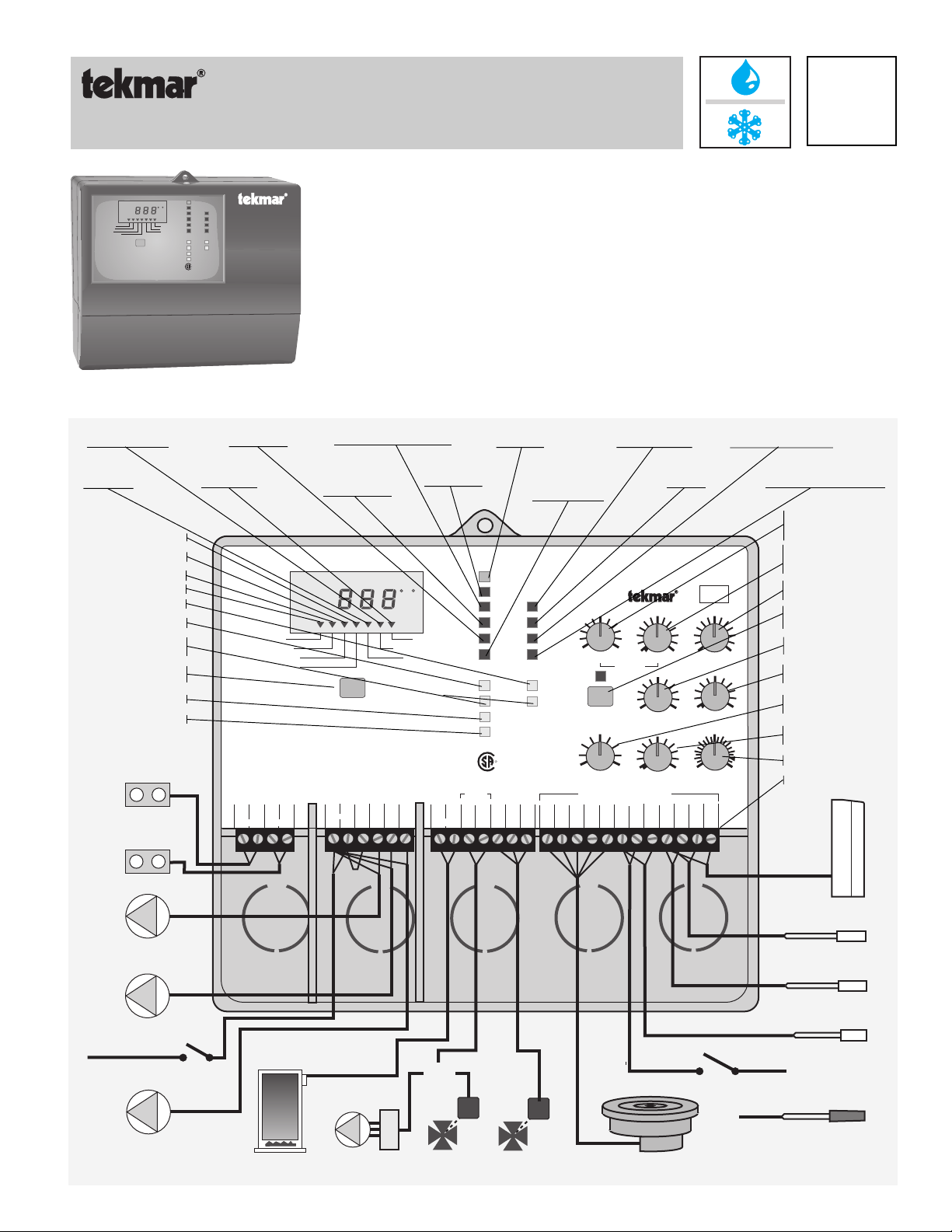
Snow Detector & Melting Control 662
The tekmar Snow Detector & Melting Control 662 is a microprocessor-based control which,
OUTSIDE
FC
Supply
Return
Slab
Boiler Return
To change between
°F and °C, press and
hold for 1 sec.
Item
Snow Detector & Melting Control 662
Mixing Operation
Power
Remote
CWCO
WWCO
Idling
Melting
Maximum
Water
Target ∆T
Actual ∆T
% Output
∆T
Maximum
Minimum
Supply
Return
Pump 1
Pump 2
Closing
Opening
Boiler
Warning
R
LR 58223
NRLT/C
together with the Snow/Ice Sensor 090, activates and controls the rate of heat delivery to a snow
melt system. This versatile control has three modulating outputs to control the heat delivery for
most pump and/or valve arrangements. Protection of both the snow melt slab and the boiler is
achieved through several safety features. Faster pick up times are also ensured through a
viscosity compensation function which optimizes the rate of heat delivery to the slab during start
up. The 662 combines all the necessary features to make snow melting safe and trouble free.
Sequence of Operation pg. 2
Installation . . . . . . . . . . pg. 3
Settings . . . . . . . . . . . . pg. 7
Display Operation . . . . pg. 8
D 662
07/99
Testing . . . . . . . . . . . . . pg. 9
Error Messages . . . . . . pg. 10
Technical Data . . . . . . . pg. 12
Limited Warranty. . . . . pg. 12
Relative Energy
usage in ∆T x Hours
Boiler return
temperature
Target slab ∆T
Actual slab ∆T
Supply temperature to slab
Slab surface temperature
Boiler pump is on
System pump is on
Valve is
opening/closing
LCD display
item select
Boiler operating
Fault warning
Output:
Melt relay is closed
when control is
in melting mode.
Output:
Warning relay is
activated if sensor
fault is detected
Water is detected
by the sensor
Current % Heat
Output to slab
Slab
Supply
Actual ∆T
Target ∆T
The Snow/Ice Sensor is installed in a hostile environment.
It should be cleaned and checked on a regular basis.
Snow Detector & Melting Control 662
Floating / Variable Speed / 4-20 mA
Use Nº 20 AWG or larger copper conductors rated for at least 75°C / 300V
1
3
2
4
Warning
Melt
Slab is warm enough,
no snow melting is required
Snow detected:
control is in
Melting mode
To change between
°F and °C, press and
hold for 1 sec.
Item
5
78
6
Com
Power
P1
Pmp
Pmp
N
Pmp
L
OUTSIDE
FC
% Output
Usage (∆T x hrs)
Boiler Return
9
10
P2
Var
Pmp
Remote Enable
Signal present
1000Ω
1112131415
4-20
Boiler
+–
120 Vac power
supply is on
Power
Remote
WWCO
Melting
Water
Maximum
Supply
Pump 1
Opening
Boiler
Warning
R
LR 58223
NRTL/C
16
Com
4-20
Opn
Mix
Mix
Control is limiting supply
temperature to Max.
Supply setting
Power
System Pumps
Variable Pump
Mix Relays
Other Relays
Enclosed Energy Management Equipment
Manufactured
in Canada by
CWCO
Idling
Maximum
∆T
Minimum
Return
Pump 2
Closing
17
18 19 202122 23
Cls
Red
Mix
Sen
39°F
34 44
Melting
Test
30°F
10
∆T Max.
Do not apply power here
Brn
Blu
Yel
Blk
Sen
Sen
Sen
Sen
Weather is too cold,
snow melting is off
Control is in
Idling mode
120 V ac 50/60 Hz 300 VA
120 V ac 6 A 1/3 hp, pilot duty 240 VA 2 A
120 V ac 50/60 Hz 2.2 A 1/6 hp, internally fused
24 V ac 10 A, pilot duty 48 VA 2 A
120 V ac 10 A 1/3 hp, pilot duty 240 VA 2 A
29°F
24
Off 35
Idling
Surface
150°F
100 200
Max. Supply
0°F
-20
50
Off
CWCO
24 25
Com
Bret
Rem
Sen
Sen
En
26
Com
Sen
25
27 28
Ret
Sen
2094
1234567
50 %
20 80
Sensitivity
100°F
60
Off 150
Min. Boil Return
130 sec
30
Motor Speed /
Pump Response
29
Sup
Out
Sen
Sen
Control is limiting heat
output to Max ∆T setting
Control is maintaining
Min. boiler return temperature
Desired slab surface
temperature during
melting mode
Desired slab surface
temperature during
idling mode
H11002
Input: Outdoor
Sensor Sensitivity to
water
Test button to initiate
test sequence
Maximum Supply
temperature
Min. Boiler Return
temperature
Max. Temperature
drop across slab
Cold Weather Cut-off
temperature
Motor Speed setting
Terminal Plugs
Sensor 070
(Included)
Date
S/N
230
tekmar
motor
Output: Turn on
system pump P1
Output: Turn on
boiler pump P2
120 Vac
Power Supply
Output:
operate pump at
varying speeds
Output:
Turn on boiler
OR
Output: control
4-20 mA device
M
M
Output: control
Floating Action
Input: System Supply
Sensor 071
Input: System Return
Sensor 071
Input: Boiler Return
Sensor 071
Input: Remote Enable
Signal.
OR
Input: Slab Sensor 072
Detects slab temperature
Input: Snow/Ice Sensor 090 installed with Sensor Socket 091.
Both of these components must be ordered separately.
only. Does not detect Snow/Ice.
(Included)
(Included)
(Included)
(Optional)
(Included)
(Optional)
Page 2

In order for this control to operate effectively, it must be installed in a well designed melting system. The Application Brochures A 662
provide a series of schematics which can be used with this control. Any deviations from these drawings must be discussed with a tekmar
factory representative to ensure that system performance is not compromised. The application drawings are not final designs - each
component within the system must be correctly sized for the control to operate effectively. It is important that the sequence of operation
and the application drawings for this control are fully understood to ensure that the control selected is compatible with its intended use.
Sequence of Operation
Powering up the control
After the Snow Detector & Melting Control 662 is powered up, the red status lights and the LCD segments are turned on for 7 seconds.
The control then displays the “Outdoor” temperature.
Melting Mode
Operation using a Snow/ Ice Sensor 090 - The control continually monitors the Snow/Ice Sensor
090. When water is detected, the “Water” light turns on and if the control is not in WWCO or
CWCO (see page 3 for an explanation of these terms), melting mode begins.
Operation using a Remote Enable - Melting mode can also be initiated if a remote enable signal
is present (terminals Com Sen and Rem Sen shorted together) and the control is not in WWCO
or CWCO. The remote enable is typically used with multiple Snow Melting Controls and Snow/
Ice Sensors. It can be also be used to manually turn the melting system on by wiring a switch
between the remote terminals. A remote enable switch must be installed when a Slab
Opening light is
on if the melting
system requires
more heat
Sensor 072 is used as this sensor cannot detect water.
Once the control is in melting mode, the Melting relay and boiler pump (relay P2 Pmp) are turned
on. After a 4 second delay, the system pump (relay P1 Pmp) is turned on and after 8 seconds, heat is applied to the snow melt system
through either a variable speed pump, a floating action mixing valve or a 4-20 mA device. The opening and closing lights indicate
whether the control is increasing or decreasing the heat applied to the snow melt system. Essay E 021 compares the use of these
devices for controlling the system temperature and also discusses the sizing and operation of the variable speed pump. Information
on floating action can be found in Essay E 000. The 4-20 mA, variable speed pump and mixing valve outputs operate simultaneously.
The 4-20 mA output can therefore be used to provide a remote readout of the pump or valve operation. The control remains in melting
mode until no water is detected for at least 30 seconds and the slab is up to temperature for at least 30 minutes. Cold Weather or
Warm Weather Cut Off can also terminate melting mode. When the control exits melting mode the boiler and system pumps are
operated for an additional 90 seconds to purge the boiler. If the control switches from melting to idling mode, the boiler is not purged.
Idling Mode
When the melting system starts off from a cold temperature, the time required for the slab to reach
“Melting” temperature can be excessive. To decrease this start up time, the slab can be maintained
at an “Idling” temperature until melting is required. The idling feature is also useful for preventing
frost and light ice formation. When the control is in idling mode, control operation is similar to melting
mode except the “Melting” and “Water” lights are off and the “Idling” light is on.
Opening light is
on if the melting
system requires
more heat
Snow melt system protection features
The 662 control has several features for protection of the snow melt system:
- to protect the slab from cracking due to thermal stresses, the control limits the rate of heat applied to the slab through a “∆T Max”
setting. The ∆T represents the difference between the slab supply and return fluid temperatures which are measured by the control.
If this temperature difference approaches the “∆T Max” setting, the “Maximum ∆T” light turns on and the control operates the valve
or pump to maintain the ∆T at the “∆T Max” setting.
- to protect the piping and other components in the system, the control limits the supply temperature to a “Max. Supply” setting. When
the melt system supply temperature approaches the maximum supply setting, the “Maximum Supply” light turns on and the control
operates the valve or pump to reduce the supply temperature.
- to prevent the flue gases in the boiler from condensing, the control limits the boiler return temperature to a “Min. Boil. Return” setting.
When the boiler return temperature approaches this setting, the “Minimum Return” light turns on and the control operates the valve
or pump to increase the boiler return temperature.
∆T compensation for changes in fluid viscosity
Glycol solutions used in snow melt systems have widely varying viscosities between high and low temperatures. As the glycol solution
temperature drops, viscosity increases causing a reduction in flow rate. This reduction in flow rate reduces the rate of heat output
if the fluid temperature drop across the slab (∆T) remains constant. To compensate for this, the control increases the Maximum ∆T.
This compensation is only applied when the fluid temperature is below 30°F, which is the temperature at which the viscosity of a typical
40% ethylene glycol / 60% water solution starts to increase significantly. The compensation feature is designed for fluids containing
40% ethylene glycol or 30 % propylene glycol; however, if the glycol percentage in the solution is lower than these values, the quality
of heat regulation is not significantly affected. When the control is compensating for viscosity changes, the “Maximum ∆T” light flashes.
Ramping the ∆T during melting system start up
When the control turns on the melting system, the “Target ∆T” is slowly ramped up to the maximum ∆T to prevent thermal shock of
the slab. If the temperature of the fluid returning to the boiler (source) is sufficient, the ramping time is less than 17 minutes. If the
heat source is not dedicated to snow melting and there are other heat demands on the source, the ramping time may be longer.
2
Power
Remote
WWCO
Melting
Water
Maximum
Supply
Pump 1
Opening
Boiler
Warning
Power
Remote
WWCO
Melting
Water
Maximum
Supply
Pump 1
Opening
Boiler
Warning
If a remote signal is
present, the Remote
light turns on
CWCO
Idling
Maximum
∆T
Minimum
Return
Pump 2
Closing
Closing light is on
if the melting
system requires
less heat
CWCO
Idling
Maximum
∆T
Minimum
Return
Pump 2
Closing
Closing light is on
if the melting
system requires
less heat
Page 3

Warm Weather Cut Off (WWCO)
n
If the “Slab” and “Outdoor” temperatures rise above the “Melting” temperature, heating the slab is
no longer required. The control therefore shuts down the melting system and enters WWCO.
During WWCO the “Closing” light remains on continuously and the heat supplied through the valve
or variable speed pump is reduced to zero. When the “Outdoor” or “Slab” temperature drops below
the “Melting” temperature, the control exits WWCO and continues with normal operation.
Cold Weather Cut Off (CWCO)
Maintaining the slab at a “Melting” or “Idling” temperature in extremely cold weather can be
expensive and may even be impossible. When it does snow at these colder temperatures, the snow
is usually dry, light and less slippery. The control therefore turns the melting system off when the
“Outdoor” temperature drops below the “CWCO” setting. During CWCO the “Closing” light remains
on continuously and the heat supplied through the valve or pump is reduced to zero. The heater
If a remote
signal is
present, the
Remote light
turns on
If water is
detected the
Water light
turns on
Power
Remote
WWCO
Melting
Water
Maximum
Supply
Pump 1
Opening
Boiler
Warning
Note:
In Cold Weather Cut
Off, the CWCO light is
on and the WWCO
light is off
CWCO
Idling
Maximum
∆T
Minimum
Return
Pump 2
Closing
Closing light is o
to turn off the
melting system
in the Snow/ Ice Sensor 090 is kept on during CWCO until the control detects snow. If snow is detected, the heater is turned off but
the control retains the snow detected information. When the outdoor temperature rises above the “CWCO” temperature, the control
exits CWCO and if the Snow/Ice Sensor 090 detected snow during CWCO, the control initiates melting mode.
Warning Light and Relay
Pump 2
If a sensor fault occurs, the Warning relay and light are turned on and an error message is given. The look-up
table provided on pages 10 and 11 can be used to determine which sensor has the fault.
Pump 1
Opening
Boiler
Warning
Closing
Exercising of the Pumps and Valves
To prevent the pumps or valves from seizing after long inactive periods, the pumps
and valves are operated after every 3 days of no operation. The Pump P1 and Pump
P2 relays are turned on for 20 seconds and the mixing valve or variable speed pump
output is run fully open and/or fully closed. During exercising, the LCD screen
alternates between two special characters as illustrated in the diagram.
Slab
Supply
Actual ∆T
Target ∆T
% Output
Usage (∆T x hrs)
Boiler Return
Slab
Supply
Actual ∆T
Target ∆T
% Output
Usage (∆T x hrs)
Boiler Return
Installation
Caution
Improper installation and operation of this control could result in damage to equipment and possibly even personal
injury. It is your responsibility to ensure that this control is safely installed according to all applicable codes and
standards. This electronic control is not intended for use as a primary limit control. Other controls that are intended
and certified as safety limits must be placed into the control circuit.
Step One Getting ready
Check the contents of this package. If any of the contents listed are missing or damaged, please refer to the Limited Warranty
and Product Return Procedure on the back of this brochure and contact your wholesaler or tekmar sales agent for assistance.
Type 662 includes:
• One Snow Detector & Melting control 662 • One Outdoor Sensor 070
• Three Universal Sensors 071 • One Slab Sensor 072
• One Data Brochure D 662 • Application Brochures A 662 • One Data Brochure D 001
Other information available:
• Essay E 021 • Essay E 000 • Essay E 600
Read Brochures A 662 and select the correct Application for your job.
Note: This control can be installed with EITHER a Snow/Ice Sensor 090 and Sensor Socket 091 OR a Slab Sensor 072. The
Snow/Ice Sensor 090 and Sensor Socket 091 are not included with the type 662 and must be ordered separately.
Carefully read the details of the Sequence of Operation sections in all applicable brochures to ensure that you have chosen the
proper control and understand its functions within the operational requirements of your system.
Step Two Mounting of the base
The control should be removed from its base by pressing down on the release clip in the wiring chamber and sliding upwards
on the control. The base is then mounted in accordance with the instructions in the Data Brochure D 001.
Step Three Rough-in Wiring
All electrical wiring terminates in the control base wiring chamber. It has standard 7/8" (22mm) knock-outs that accept all common
wiring hardware and conduit fittings. Before breaking out the knock-outs, check the wiring diagram and select those sections of
the chamber with common voltages. Do not allow the wiring to cross over sections as safety dividers, installed later, prevent this.
Power should not be applied to any of the wires during the rough-in wiring stage.
•
EITHER:
base.
•
OR:
See page 5 for very important details on sensor location and installation.
• Run the wiring from the other system components to the base.
• Run 120 V ac to the power terminals on the control.
• Multi-strand 16 AWG wire is recommended for the 120 V ac wiring due to its superior flexibility and ease of installation into the
terminal.
Install the Snow/Ice Sensor 090 according to the instructions in Data Brochure D 090 and run the wiring back to the
See Data Brochure 090 for very important details on sensor location and installation.
Install the Slab Sensor 072 according to the instructions in the Data Brochure D 001 and run the wiring back to the base.
Use a clean 120 V ac power source to ensure proper operation.
3
Page 4
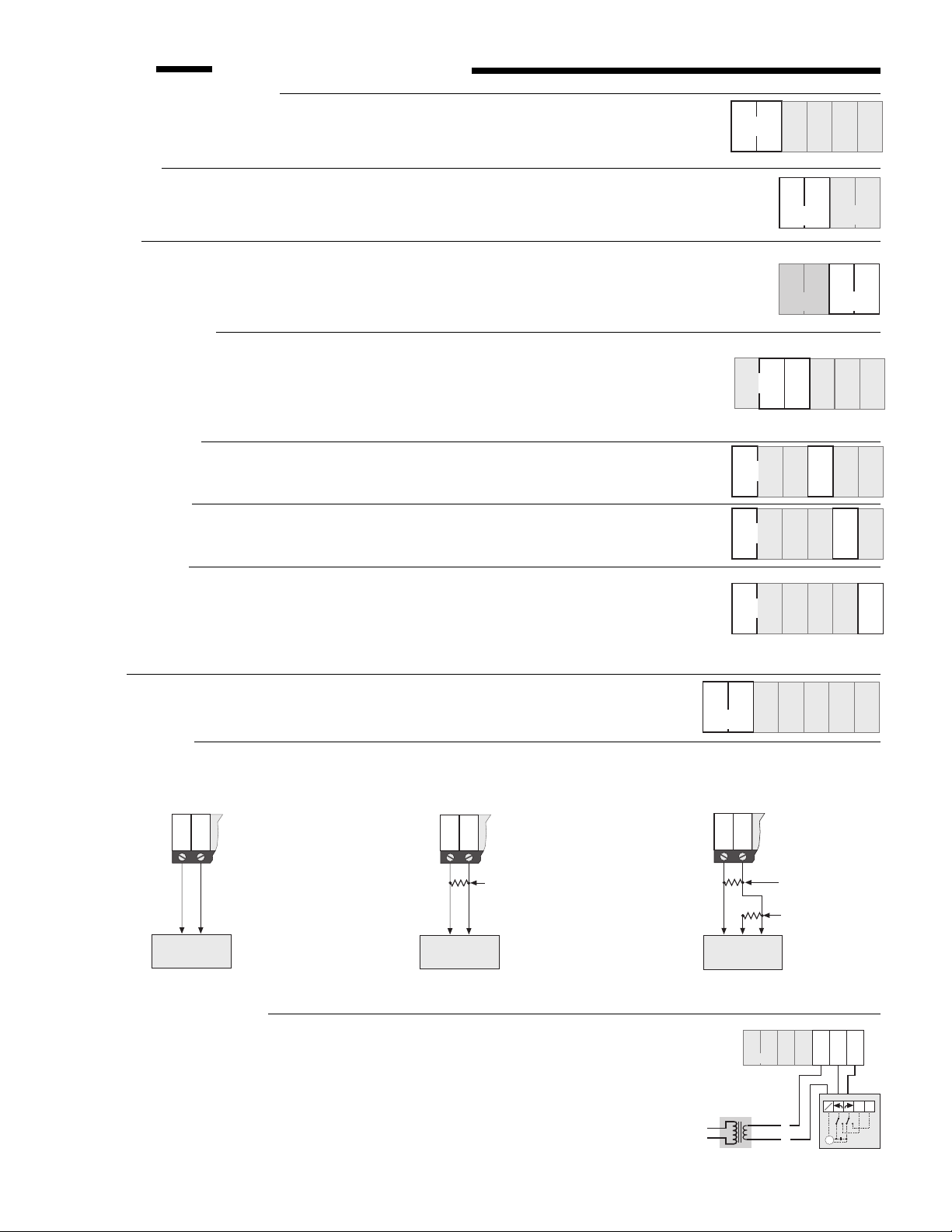
Step Four Electrical connections to the control
Power and output connections
• The installer should test to confirm no voltage is present at any of the wires.
• Install the control back into the base by sliding it down until it snaps in firmly.
• Connect the 120 V ac power supply to terminals
Melt Output
• Connect the melting device to terminals
Melt
(dry) relay contact inside the control which closes when the control enters melting mode. The
most common devices to be enabled by the 662 are pumps, heating devices or other controls.
Warning
• If desired, connect a warning device to terminals
a dry relay contact inside the control which closes when there is a sensor or wiring fault.
Caution
: The 662 is an operating control and is not certified as a safety device. If safety
considerations are critical, a separate alarm system must be installed.
Pump Power Supply
• Terminal
and
Com Pmp
P2 Pmp
(7) is the common power supply terminal for both terminals
(9).
• If the pumps P1 and P2 are operated from the same 120 V ac power supply as the control,
connect the terminal
Power L (6)
to the terminal
• If a separate power supply is required for P1 and/or P2, contact tekmar for details.
System Pump P1
• Connect the System Pump to terminals
Power N — P1 Pmp
to a dry relay contact which closes when the control requires System Pump operation.
Boiler Pump P2
• Connect the Boiler Pump to terminals
Power N — P2 Pmp
to a dry relay contact which closes when the control requires Boiler Pump operation.
Variable Speed
• Connect the variable speed pump to terminals
operated by this circuit must be permanent capacitor, impedance protected with a locked rotor
current less than 2.2 amps. The Snow Detector & Melting Control 662 has an internal 2.5 amp
fuse for overload protection.
This fuse is not field replaceable.
return and repair procedures if this fuse is blown.
Boiler
• Connect the boiler or the boiler control to the terminals
lead to a dry relay contact which closes when the control requires boiler operation.
4-20 mA Device
• Connect the positive 4 - 20 mA lead to terminal
resistance allowed in the 4 - 20 mA circuit is 1000 Ω. The 4 - 20 mA output can be converted to a voltage output by connecting
a resistor between terminals 13 and 14.
Power N — L
(5 and 6).
(1 and 2). These terminals lead to an unpowered
Warning
Com Pmp (7)
(3 and 4). These terminals lead to
.
(5 and 8). These terminals lead
(5 and 9). These terminals lead
Power N —Var Pmp
(5 and 10).
Contact tekmar for details on
Boiler
(11 and 12). These terminals
4-20 +
(13) and the negative 4 - 20 mA lead to terminal
P1 Pmp
Pumps
(8)
11
Boiler
56
Power
N L
5
Power
N L
Power
N L
Power
N L
Power
N L
13
12
4-20
+
4 - 20 –
89
7
Com
P1
Pmp
Pmp
2
1
Melt
2
1
Melt
89
7
6
Com
P1
Pmp
Pmp
7
Com
Pmp
7
Com
Pmp
7
Com
Pmp
8
P1
Pmp
8
P1
Pmp
8
P1
Pmp
65
65
65
14
Com
4-20
Mix
–
(14). Maximum
10
Var
P2
Pmp
Pmp
34
Warning
34
Warning
10
Var
P2
Pmp
Pmp
9
10
Var
P2
Pmp
Pmp
10
9
Var
P2
Pmp
Pmp
9
10
Var
P2
Pmp
Pmp
1615
17
Opn
Cls
Mix
Mix
1413
1
4-20
C
4-20
–
+
M
+
–
4 - 20 mA
Actuating Motor
Connection to Operate
a 4 - 20 mA Device
Operate a 1 - 5 Vdc or 2 - 10 Vdc Device
1413
1
4-20
4-20 C
–
+
M
500 Ω resistor
4-20 mA converted
to 2-10 Vdc output
OR
250 Ω resistor
4-20 mA converted
to 1-5 Vdc output
+
–
1-5 or 2-10 Vdc
Actuating Motor
Converting the 4 - 20 mA Output to
Floating Action Mixing Valve
• Connect one side (R) of a 24 V ac transformer to terminal
• Connect the (C) side of the transformer to terminal
N/C
Com Mix
(15).
on the tekmar 010 Actuating Motor.
For other makes of actuating motors, refer to the manufacturers' installation instructions.
• Connect the OPEN terminal of the Actuating Motor (CCW) to the terminal
Opn Mix
the control. This terminal leads to a relay contact which closes to provide 24 V ac to open
the valve.
• Connect the CLOSE terminal of the Actuating Motor (CW) to the terminal
Cls Mix
the control. This terminal leads to a relay contact which closes to provide 24 V ac to close
the valve.
4
(16) on
(17) on
14
13
1
4-20
C
4-20
–
+
M
66.5 Ω resistor
237 Ω resistor
B
R
W
0 - 135Ω "Slidewire"
Actuating Motor
Converting the 4 - 20 mA Output to
Operate a 0 - 135Ω Actuating Motor
13
12
24Vac
4-20
R
C
14
4-20
+
–
11
Boiler
Separate Class II
Transformer
L
N
15
Com
Mix
16
17
Opn
Cls
Mix
Mix
N
12
C
M
type 010
Page 5

Sensor and unpowered input connections
2
R
E
2
e
E
Power should never be applied to these terminals. Damage to the control will result.
Snow/Ice Sensor 090 (Must be ordered separately)
For automatic detection of snow or ice, the tekmar Snow/Ice Sensor 090 is required. This sensor must be installed flush with
the slab surface and 1/2 way between the heating pipes.
See Data Brochure D 090 for installation instructions regarding the
Snow/Ice Sensor 090 and Sensor Socket 091.
• Connect the red wire from the sensor cable to terminal
• Connect the black wire from the sensor cable to terminal
• Connect the blue wire from the sensor cable to terminal
• Connect the yellow wire from the sensor cable to terminal
• Connect the brown wire from the sensor cable to terminal
Red Sen
Blk Sen
Blu Sen
Yel Sen
Brn Sen
(18).
(19).
(20).
(21).
(22).
18 19 21
20
Blk BrnRed Blu Yel
Sen
Sen Sen Sen Sen
22
Slab Sensor 072
If a Snow/Ice Sensor 090 is not ordered, the Slab Sensor 072 must be installed.
072 sensor, a remote enable switch turns the melting system on.
wires to terminals
Blk Sen — Brn Sen
(19 and 22). The 072 sensor cable is 20 feet (6m) long
Connect the two sensor
but it can be extended to a maximum overall length of 1000 feet (300 m). If extension becomes
necessary, splices should be properly soldered and waterproofed and be protected in an
accessible, waterproof junction box. Use at least 18 AWG wire for extensions.
Important Note:
control. The Slab Sensor 072 must be installed
1" (25 mm) below the surface of the slab.
Proper sensor placement is critical for correct operation of the 662
1/2 way between the heating pipes and
Although the 072 sensor can be placed directly
With the
19
Blk
Sen
20
Sen Sen
1/ 2 X
18 21
Red Blu Yel
Sen
22
Brn
Sen
X
into the slab, we recommend that the sensor be installed in tubing or conduit in such a
manner that the sensor can be removed and replaced in case of failure.
Outdoor Sensor
• Connect the two wires from the Outdoor Sensor 070 to the
terminals
Com Sen — Out Sen
(26 and 29).
System Supply Sensor
• Connect the two wires from the Universal Sensor 071 – which should
be mounted on the system supply pipe to the slab – to terminals
Sen — Sup Sen
(26 and 28).
Com
18 19 21
20
Blk BrnRed Blu Yel
Sen
Sen Sen Sen Sen
18 19 21
20
Blk BrnRed Blu Yel
Sen
Sen Sen Sen Sen
22
22
23
Com
Sen
23
Com
Sen
24 25 26
RemEnBret
Sen
24 25 26
RemEnBret
Sen
Com
Sen
Com
Sen
Ret
Sen
Ret
Sen
System Return Sensor
• Connect the two wires from the Universal Sensor 071 – which should
be mounted on the system return pipe from the slab – to terminals
Com Sen — Ret Sen
(26 and 27).
18 19 21
20
Blk BrnRed Blu Yel
Sen
Sen Sen Sen Sen
22
23
Com
Sen
24 25
RemEnBret
Sen
26
Com
Sen
27
Ret
Sen
Boiler Return Sensor
• Connect the two wires from the Universal Sensor 071 – which should
be mounted on the return pipe to the boiler– to terminals
— Bret Sen
(23 and 25).
Remote Enable Signal (Optional)
• If a remote device is used to enable the control, connect the two
wires from the device to terminals
Com Sen — Rem Sen
(23 and 24).
Com Sen
18 19 21
20
Blk BrnRed Blu Yel
Sen
Sen Sen Sen Sen
18 19 21
20
Blk BrnRed Blu Yel
Sen
Sen Sen Sen Sen
22
22
23
Com
Sen
23
Com
Sen
RemEnBret
RemEnBret
24 25 26
Sen
24 25 26
Sen
Com
Sen
Com
Sen
27 28
Ret
Sen
27 28
Ret
Sen
23
Com
Sen
23
Com
Sen
27 28
Sup
Sen
27 28
Sup
Sen
28
Sup
Sen
Sup
Sen
Sup
Sen
R
1"
(25 mm)
29
Out
Sen
29
Out
Sen
29
Out
Sen
29
Out
Sen
29
Out
Sen
10A
1234
12 4
Melt
relay closes
when in
melting mode
10A
Warning
Melt
Warning
relay closes when a
sensor fault occurs
56789
Power
LN
System Pump
relay closes to turn
on System Pump
Power
Requirements
120 V ac ± 10%,
50/60Hz.
6A
6A
2.2A
10A
1000
10A 10A
Ω
10
Com
Com
PmpP1PmpP2Pmp
Boiler Pump
relay closes to
turn on Boiler
Pump
Var
Pmp
Variable Speed
Pump
output varies from
0% to 100%
Boiler
Boiler
relay closes
to turn on
boiler
Note: This is not a wiring diagram. For
detailed wiring schematics refer to the
Application Brochures A 662.
4-20
4-20
+
4 to 20 mA
modulating
output
Mix
-
Actuating Motor
5
Do not apply power here
17 18 19 20 21 22 23 24 25 26 27
Red
Blk
Blu
Yel
Brn
Com
Sen
Brown
Sen
Rem
En
Opn
Mix
relays close to
operate Mixing
Valve motor
Cls
Mix
Sen
Red
Sen
Black
Snow/Ice
Sen
Blue
Sensor
090
Sen
Yellow
OR
Slab
Sensor 072
or 073
Bret
Com
Sen
Sen
Boiler
Return
Sensor
071
System
Return
Sensor
071
Remote Enable
signal
(Optional)
Ret
Sen
662
2811 12 13 14 15 16
Sup
Sen
29
Out
Sen
Outdoor
Sensor
070
Supply
Sensor
071
Page 6

Step Five Testing the wiring
Slab
Supply
Actual ∆T
Target ∆T
% Output
Usage (∆T x hrs)
Boiler Return
• Before applying power to the control for testing, each terminal plug must be unplugged from its
6
header on the control. Pull straight down to unplug.
• These tests are to be performed using standard testing practices and procedures and should only
be carried out by properly trained and experienced persons.
• A good quality electrical test meter capable of reading from at least 0 — 200 Volts ac, and at least
0 — 2,000,000 Ohms, is essential to properly test this control.
Test the sensors
• In order to test the sensors, the actual temperature at each sensor must be known. A good quality
digital thermometer with a surface temperature probe is recommended for ease of use and
accuracy of testing. Where a thermometer is not available, a spare sensor can be strapped
alongside the one to be tested and the readings compared. Test the Snow/Ice Sensor 090
according to the instructions in brochure D 090, and the remaining sensors according to the
brochure D 001.
Test the power supply
• Before applying power, make sure exposed wiring or terminals are not grounded or in contact with other wires. Turn on the
120 V ac power and, using an AC voltmeter, measure the voltage between terminals
Power N – L
(5 and 6). You should measure
between 110 and 130 V ac.
Test the Outputs
• If a device is connected to the
Melt
(1 and 2) terminals, make sure power to the circuit is off and install a jumper in the terminal
plug between terminals 1 and 2. When the device is powered up, it should operate. If it does not turn on, check the wiring
from the terminal plug to the device and refer to any installation or trouble shooting information supplied with the device. If
the device is operating properly, disconnect the power and remove the jumper.
• Repeat this procedure for any devices connected to the
• If a pump is connected to the
between the
Com Pmp — P1 Pmp
P1 Pmp
(8) terminal, make sure power to the circuit is off and install a jumper in the terminal plug
(7 and 8) terminals. When the circuit is powered up, the pump should start. If it does not,
Warning
(3 and 4) terminals and the
Boiler
check the wiring from the terminal plug to the pump and refer to any installation or troubleshooting information supplied with
the pump. If the pump operates properly, disconnect the power and remove the jumper. Repeat this procedure for a pump
connected to the
• If a variable speed pump is connected to the
and install a jumper in the terminal plug between the
P2 Pmp (9)
terminal.
Power N — Var Pmp
Power L — Var Pmp
(5 and 10) terminals, make sure power to the circuit is off
(6 and 10) terminals. When the 120 V ac circuit is
powered up, the variable speed pump should operate at full speed. If it does not, check the wiring from the terminal plug to the
pump and refer to any installation or troubleshooting information supplied with the pump. If the pump operates properly,
disconnect the power and remove the jumper.
• A separate 24 V ac transformer is used to drive the actuating motor for the mixing valve. Make sure power to the transformer
is off and install a jumper in the terminal plug between terminals
Com Mix – Opn Mix
(15 and 16). When the transformer is
powered up, the mixing valve should drive fully open and then stop. Turn off the power to the transformer, remove the jumper
and install it in the terminal plug between terminals
Com Mix – Cls Mix
(15 and 17). When the transformer is powered up,
the mixing valve should drive fully closed and then stop. If it does, disconnect the power and remove the jumper.
• The 4 - 20 mA output terminals (13 and 14) cannot be tested without power applied to the control. Since no power is supplied
to the control at this point, the 4 - 20 mA output cannot be tested. Please refer to the operation test below.
Connect the control
• Turn the power off and make sure all test jumpers have been removed from the plugs.
• Connect the plugs to the control by carefully aligning them with their respective headers and pushing them upwards. The plugs
should snap firmly into the headers.
• Install the supplied safety divider(s) between the low voltage (less than 30 V ac) and the line voltage (120 V ac) wiring chambers.
Apply power to the control.
5
Power
N
L
Disconnect terminal
plug from its header
(11 and 12) terminals.
Com
Pmp
10
9
8
7
Var
P2
P1
Pmp
Pmp
Pmp
Test the 4 - 20 mA output
The 4 - 20 mA device can be tested as follows:
• Connect the positive wire from the 4 - 20 mA device to terminal 13 on the control.
• Connect the negative wire from the 4 - 20 mA device to the red (+) lead on the
milliamp meter.
• Connect the black (-) lead from the milliamp meter to terminal 14 on the control.
• When the Opening light turns on, the initial percentage output is zero and the meter
should read 4 mA.
• As the % Output increases, the meter reading should increase until 100% Output
is reached at which point the meter should read 20mA.
• When the Closing light comes on the meter should start at 20mA and eventually
reach 4mA when the display shows 0% Output.
6
4-20
+
M
Reading should
be 4 mA
4-20
1413
1
C
–
M
Test the 4 - 20 mA
output using a
milliamp meter
1000 mA = 1 amp
6.4 mA
Milliamp
-
+
Slab
Supply
Actual ∆T
Target ∆T
Reading should
be 20 mA
% Output
Usage (∆T x hrs)
Boiler Return
Page 7

Settings
Step Six Essential control settings
Before adjusting the dial settings, read through the sequence of operation to ensure that you understand how the control operates.
The dials are factory set at the midpoint of each setting. This reflects typical settings for many systems and is therefore a good
starting point.
Melting Surface Temperature
The “Melting” dial setting is the desired slab surface temperature when the control is in melting mode and is
also used as the Warm Weather Cut Off temperature. The “Melting” temperature is usually set based on local
weather conditions. In some areas, heavy snowfall can load a slab at temperatures well above freezing; in
these areas, the dial should be set higher. If the melting system response is sluggish, increasing the “Melting”
dial setting can cause the system to melt faster; however, it is important to remember that increasing this
setting generally increases energy consumption.
Idling Surface Temperature
The “Idling” dial setting is based on the requirements of the user. If minimizing the time required for the slab
to reach “Melting” temperature is important then the dial is set slightly below freezing (<32°F). If black ice or
frost formation is a concern, the dial is set slightly above freezing (>32°F). It is important to remember that
“Idling” increases energy consumption. “Idling” can also be turned Off.
Water Detection Sensitivity
The sensitivity of the Snow/Ice Sensor to water can be adjusted using the “Sensitivity” dial. As snow becomes
contaminated with dirt, and as the sensor surface itself becomes dirty, the control may incorrectly indicate
the presence of water. If this condition occurs, clean the surface of the sensor and/or turn down the sensitivity
setting. If the snow and rain in your area is very clean, the sensitivity setting may need to be increased before
snow is detected.
Note:
The Snow/Ice Sensor 090 is installed in a hostile environment and should be cleaned on a regular basis with a wire
brush. After cleaning, check operation by pressing the test button to cycle the control through the test routine.
Maximum Supply Temperature
Some tubing manufacturers recommend that their products not be operated continuously at temperatures
greater than 140°F (60°C). Engineers also recommend that concrete slabs not be subjected to temperatures
in excess of 160°F (70°C). This dial setting permits the installer to limit the maximum temperature of the water
supplied to the snow melting slab. If the system supply water temperature approaches this setting, the
“Maximum Supply” light turns on and the control operates the mixing valve (or variable speed pump) to limit
the output and reduce the “Supply” temperature.
Minimum Boiler Return Temperature
To prevent problems of flue gas condensation in the boiler, this adjustment is set to the minimum boiler return
temperature as specified by the boiler manufacturer. When the boiler return approaches this setting, the
“Minimum Return” light turns on and the control operates the mixing valve (or variable speed pump) to limit
the output until the boiler return can warm up. If a minimum boiler return temperature is not required, as with
condensing or electric boilers, this adjustment can be set to “Off”.
∆
T Max. (Maximum Rate of Heat Delivery )
The 662 control limits the rate of heat applied to a slab to prevent excessive thermal stress. The rate of heat
delivery to the slab is dependant on the difference between the melting system supply and return
temperatures. The control measures these temperatures and calculates the difference to give the ∆T. If this
calculated ∆T approaches the “∆T Max” setting, the control operates the valve or pump to maintain the ∆T
at the “∆T Max” setting. The “∆T Max” dial is normally set at 5°F to 10°F above the design ∆T or it is specified
directly by the system designer. If this is not the case, set the dial at 30°F.
Note: The control may exceed its “∆T Max” setting if the supply temperature is lower than 30°F (see page 2 —
∆T compensation for changes in fluid viscosity).
CWCO (Cold Weather Cut Off)
The “CWCO” is the lowest temperature at which the melting system continues to operate. This temperature
is set based on the capacity of the snow melt system and the economics of melting in extreme conditions.
Motor Speed /
Pump Response
Pump Response (variable speed pump) - When using a variable speed pump, this dial sets the minimum
time required for the injection pump to go from 0% to 100% speed (ramp up). The primary purpose of limiting
the pump ramp up time is to avoid instability. If the pump ramps up faster than the snow melt system can
respond, the pump may continually ramp up and down trying to satisfy the snow melt system. For example:
A heat exchanger between the boiler loop and the system loop with heavy steel pipe that is slow to transfer
heat, has a delay between the time the control signals the pump to add heat to the system and the time the heat can affect
the system and be sensed by the control. To prevent oscillations of the pump speed, the “Pump Response” is set to a longer
time. In a system with a low mass, dedicated, high input boiler and no heat exchanger, the system responds faster and therefore
a shorter time can be set on the “Pump Response” dial. To avoid pump instability, experimentation is usually required; however,
most standard installations work well with settings in the 30 to 50 second range.
34 44
Melting
29°F
24
Off 35
Idling
Surface
50%
20 80
Sensitivity
150°F
100 200
Max. Supply
100°F
60
Off 150
Min. Boil. Return
10
∆T Max
0°F
-25
Off
CWCO
130 sec
30
Motor Speed /
Pump Response
39°F
Surface
30°F
50
25
230
tekmar
motor
7
Page 8

Motor Speed/
Pump Response (con't)
Motor Speed (mixing valve and 4-20 mA outputs) - When operating a valve, the control uses the information from the “Motor
Speed” dial setting to synchronize various control actions to the valve position and its rate of change. Set this adjustment to match
the time required for the actuating motor to drive from the fully closed to the fully open position.
The 662 Display & Indicator Lights
POWER-UP DISPLAY
Slab
Supply
Actual ∆T
Target ∆T
ACTUAL ∆T
Slab
Supply
Actual ∆T
Target ∆T
After power-up,
OUTSIDE
°F°
C
% Output
Usage (∆T x hrs)
Boiler Return
°
F
% Output
Usage (∆T x hrs)
Boiler Return
the control
shows the
"OUTSIDE"
temperature
Press and
release the
item button
Item
OUTDOOR TEMPERATURE SLAB SURFACE TEMP.
Slab
Supply
Actual ∆T
Target ∆T
TARGET ∆T
Slab
Supply
Actual ∆T
Target ∆T
Usage (∆T x hrs)
Boiler Return
OUTSIDE
°
F
% Output
Usage (∆T x hrs)
Boiler Return
°
F
% Output
Press and
release the
item button
Item
Press and
release the
item button
Item
Slab
Supply
Actual ∆T
Target ∆T
BOILER RETURN TEMP.
Slab
Supply
Actual ∆T
Target ∆T
°
F
% Output
Usage (∆T x hrs)
Boiler Return
Usage (∆T x hrs)
Boiler Return
Press and
release the
item button
Item
% Output
Press and
release the
item button
SYSTEM SUPPLY TEMP.
Slab
Supply
Actual ∆T
Target ∆T
Item
Slab
Supply
Actual ∆T
Target ∆T
°
F
Usage (∆T x hrs)
Boiler Return
ENERGY USAGE
Usage (∆T x hrs)
% Output
Boiler Return
% Output
Press and
release the
item button
Item
Press and
release the
item button
% HEAT OUTPUT
Press and hold the item
button for at least 1
second to switch
Item
between °F and °C
Slab
Supply
Actual ∆T
Target ∆T
% Output
Usage (∆T x hrs)
Boiler Return
Press and
release the item
button to scroll
through the
displays again
• Outdoor temperature is the temperature measured by the Outdoor Sensor 070.
• Slab Surface temperature is the temperature of the slab surface as measured by the Snow/Ice Sensor 090. If a Slab Sensor 072
is used, the control provides a best guess for the slab surface temperature when the sensor is placed 1" below the surface.
• System Supply temperature is the temperature of the water/glycol solution entering the slab. This temperature may be limited by
the control to protect the snow melting system components (see Settings - Max. Supply).
• Actual
∆T is the difference between the system supply and return temperatures which gives an indication of the present heat output
to the melt system. The Actual ∆T may be limited by the control to protect the slab (see Settings - ∆T Max).
• Target
∆T is the ∆T (heat output) that the control is trying to achieve. If the Actual ∆T is below the Target ∆T, the control is trying to
increase the heat to the slab. The Actual ∆T may never reach the Target ∆T because the system supply or boiler return temperatures
may be limited (see Settings -Max. Supply, Min. Boil. Return).
• Boiler Return Temperature is the temperature of the fluid entering the boiler. This sensor reading may cause the control to limit the
heat output to the slab in order to protect the boiler (see Settings - Max Boil. Return).
• Relative Energy Usage ( ∆T x hours). This display allows the user to estimate the amount of energy used by the snow melt system.
The relative energy usage is displayed by alternating between two numbers. When the °C or °F segment is off, the thousands are
display . When the °C or °F segment is on, the units are displayed . The energy consumption can be estimated by multiplying the
∆T x hrs by the system flow rate (in US GPM) and by the constant K given in the adjacent table. The accumulated energy usage
information can be cleared while the control is in the energy usage display. To do this, press and hold the item button for 1 second
and then press the test button.
Example - ∆T x hrs = 005 (thousands) 225 (units) = 5225 °F x hours
System flow = 20 US GPM
Fluid = 40% glycol & 60% water, therefore K = 462
Energy Usage = 5225 x 20 x 462 = 48,279,000 BTU
K values are calculated averages for
most ethylene glycol
solutions at 50°F
(10°C). K increases
with higher temperatures.
% Glycol by
weight
0%
10%
20%
30%
40%
50%
Freezing
point
32°F
25°F
15°F
3°F
-13°F
-35°F
@ 50°F
Item
500
496
487
477
462
439
K
• % Output - If a variable speed pump is used, this display indicates the percentage of maximum flow through the pump. If the pump
flow rate is 50% of maximum flow, the % Output is 50%. If floating valve action is used, this display indicates the percentage the valve
is open. If the valve is half open, the % Output is 50%. If a 4-20 mA device is used, this display indicates the percentage of current
output (between 4 and 20 mA) supplied to the device. If the % Output is 50%, the control is delivering 12 mA to the device.
8
Page 9

Indicator lights
y
m
Power light on • The 120 V ac power supply is connected and the control is energized.
Remote light on • The remote enable input is activated.
WWCO light on • The control is in Warm Weather Cut Off.
CWCO light on •
The control is in Cold Weather Cut Off.
Melting light on • The control is in melting mode.
Idling light on • The control is in idling mode.
Water light on • The snow/ice sensor is detecting the presence of water.
Maximum ∆T light • The control is limiting the temperature drop through the slab to the ∆T Max setting.
Max. Supply light • The control is limiting the supply temperature to the Max. Supply setting.
Min. Return light • The control is operating to keep the boiler return fluid hotter than the Min. Boil. Return setting.
Pump 1 light • The system pump (P1) relay is on.
Pump 2 light • The boiler pump (P2) relay is on.
Test light on • The control is proceeding through the programmed test routine.
Opening light on • The Open relay is on.
Closing light on • The Close relay is on.
Boiler light on • The Boiler relay is on.
Warning light on • The Warning relay is on.
Testing the Control Functions
Step Seven Operational test of control functions
LCD display, indicator lights and Snow/Ice Sensor
When the test button is pressed the red status lights and the LCD segments are turned on
for 7 seconds. The current to the Snow/Ice Sensor's internal heater is then increased and
if the temperature at the centre of the sensor does not rise at least 2°F within 45 seconds
an error message is given. If the centre of the sensor is hotter than 120°F or the outdoor
temperature is below -5°F, the control skips this part of the test. During the 45 seconds,
the control continues with the rest of the test sequence.
Warning on
The Warning relay and light turn on and the LCD shows “W A” to indicate that the external
Warning device is being tested. If the warning device does not activate, the wiring from the
control should be checked and the warning device examined for possible faults. After 10
seconds, the “Warning” light and relay are turned off and the test continues.
Note: The test routine can be halted at this, or any of the following steps, by pushing the Test button once. If this is down, the “Test”
light flashes and the control is held in a pause mode for 5 minutes after which time it automatically exits the test routine. Pushing
the “Test” button during the 5 minute pause allows the control to resume the test routine at the next step.
Melting on
The “Melting” light and relay turn on and the LCD shows “ME” to indicate that the melting
device is being tested. If the device connected to the melt relay does not activate, there
may be a fault with the wiring to the melting device or with the melting device itself - check
both. After 10 seconds, the “Melting” light and relay are turned off and the test continues.
Boiler Pump P2 on
The “Pump P2” light and relay turn on and the LCD shows “P 2” to indicate that Pump P2
is being tested. If the pump does not turn on, the wiring to the pump and the pump itself
should be checked. This pump remains on through the next part of the test sequence.
Boiler Pump P2 on and Boiler on
After Pump P2 has been on for 10 seconds, the “Boiler” light and relay are turned on and
the LCD shows “b” to indicate that the boiler is being tested. If the boiler does not turn on,
check the wiring to the boiler and the boiler itself. After another 10 seconds, both the boiler
and the boiler pump are turned off.
Pump P1 on
The Pump P1 relay and light turn on and the LCD shows “P 1” to indicate that Pump P1
is being tested. If the pump does not turn on, check the wiring to the pump and the pump
itself. After 10 seconds, the “Pump P1” light and relay turn off and the test continues.
Opening on — % Output Increasing
The “Opening” light and relay turn on and the LCD flashes between
“OPn” and the current “% Output”. The time for the device to go from 0%
to 100% is set on the “Motor Speed / Pump Response” dial. During this
time, the 4-20 mA, mixing valve or variable speed pump output should
increase from 0 to 100 %. If the device does not operate or the output
does not increase, check the wiring to the device and the device itself.
9
OUTSIDE
°F°
C
% Output
% Output
Power
Remote
WWCO
Melting
Water
Maximum
Supply
Pump 1
Opening
Boiler
Warning
CWCO
Idling
Maximum
∆T
Minimum
Return
Pump 2
Closing
Pump 1
Opening
Boiler
Warning
Power
Remote
WWCO
Melting
Water
Maximum
Suppl
Pump 1
Opening
Boiler
Warning
Pump 1
Opening
Boiler
Warning
Pump 1
Opening
Boiler
Warning
Pump 1
Opening
Boiler
Warning
Te s t
Pu
Clo
CWCO
Idling
Maximum
∆T
Minimum
Return
Pump 2
Closing
Pump 2
Closing
Pump 2
Closing
Pump 2
Closing
Page 10

Closing on — % Output Decreasing
After the Opening relay has turned off, the “Closing” light and relay turn
on and the LCD flashes between "CLS" and the current “% Output”. The
time for the device to go from 100% to 0% is set on the “Motor Speed /
Pump Response” dial. During this time, the 4-20 mA, mixing valve or
variable speed pump output should decrease from 100 to 0 %.
% Output
Pump 1
Opening
Boiler
Warning
Pump 2
Closing
Step Eight Troubleshooting
% Output
First observe the system operating parameters. The source of the problem can often be found by noting a temperature or time
reading which seems unreasonable. The indicator lights are also useful in assessing the current state of the control system.
Observing what the control is doing, and understanding the sequence of operation greatly aids in isolating the problem. The next
step is to press the test button and observe the system components working in sequential order. If a fault in a sensor or its wiring
is detected during or after the test sequence, an error message is displayed. The error message look up table provided below
can be used to locate the fault. Once the error is identified, refer to Step Five for testing of the wiring and sensors. After any repair
has been completed, press the Test button to confirm that correct operation has been restored.
Step Nine Before you leave
• Make sure wiring dividers are installed in their proper locations between compartments having different voltages.
• Install the wiring cover over the wiring chamber and secure it to the base with the two screws provided. Place the front cover on
the control and snap it into place. Install a lock if security is required.
•
Place this brochure, and all other brochures relating to the installation, in the protective plastic bag supplied with the control. Place
the bag in a conspicuous location near the control for future reference.
• It is important to explain the operation of the control and melting system to all users who may be operating it.
Error Messages
If a fault occurs during normal operation or during the test routine, the LCD flashes back and forth between the word "Err"
and one of the error codes listed.
OUTDOOR SENSOR – OPEN CIRCUIT
Check the Outdoor Sensor and wiring from the terminal plug to the sensor. When
the control has this error, it continues to operate the system assuming an outdoor
temperature of 20°F (-6.6°C)
OUTDOOR SENSOR – SHORT CIRCUIT
Check the Outdoor Sensor and the wiring from the terminal plug to the sensor. When
the control has this error, it continues to operate the system assuming an outdoor
temperature of 20°F (-6.6°C)
SUPPLY SENSOR – OPEN CIRCUIT
Check the System Supply Sensor and the wiring from the terminal plug to the
sensor. When the control has this error, the melting system is shut down.
SUPPLY SENSOR - SHORT CIRCUIT
Check the System Supply Sensor and the wiring from the terminal plug to the sensor.
When the control has this error, the melting system is shut down.
SYSTEM RETURN SENSOR - OPEN CIRCUIT
Check the System Return Sensor and the wiring from the terminal plug to the sensor.
When the control has this error, the melting system is shut down.
SYSTEM RETURN SENSOR – SHORT CIRCUIT
Check the System Return Sensor and the wiring from the terminal plug to the sensor.
When the control has this error, the melting system is shut down.
BOILER RETURN SENSOR – OPEN CIRCUIT
Check the Boiler Return Sensor and the wiring from the terminal plug to the sensor.
When the control has this error, the melting system is shut down unless the "Min. Boil
Return" dial is turned off.
BOILER RETURN SENSOR – SHORT CIRCUIT
Check the Boiler Return Sensor and the wiring from the terminal plug to the sensor.
When the control has this error the melting system is shut down.
090 YELLOW SENSOR – OPEN CIRCUIT
Check the 090 yellow temperature sensor (black and yellow wires, terminals 19 &
21), and the wiring from the terminal plug to the sensor. When the control has this
error, the melting system is shut down.
10
Page 11

090 YELLOW SENSOR – SHORT CIRCUIT
Check the 090 yellow temperature sensor (black and yellow wires, terminals 19 &
21), and the wiring from the terminal plug to the sensor. When the control has this
error the melting system is shut down.
090 BROWN SENSOR (or SLAB SENSOR 072) – OPEN CIRCUIT
Check the wiring to the 090 brown temperature sensor (black and brown wires,
terminals 19 & 22) or the Slab Sensor 072 (terminals 19 & 22). When the control has
this error, the melting system is shut down.
090 BROWN SENSOR (or SLAB SENSOR 072) – SHORT CIRCUIT
Check the wiring to the 090 brown temperature sensor (black and brown wires,
terminals 19 & 22) or the Slab Sensor 072 (terminals 19 & 22). When the control has
this error, the melting system is shut down.
WATER DETECTION CIRCUIT – OPEN CIRCUIT
Check the 090 water detection circuit (black and blue wires, terminals
19 & 20) according to brochure D 090. When the control has this error, the melting
system can only be operated using a remote enable signal.
WATER DETECTION CIRCUIT – SHORT CIRCUIT
Check the 090 water detection circuit (black and blue wires, terminals
19 & 20) according to brochure D 090. When the control has this error, the melting
system can only be operated using a remote enable signal.
INTERNAL CONTROL SENSOR – OPEN OR SHORT CIRCUIT
The control has an internal temperature sensor which monitors the temperature
inside the enclosure. If this sensor develops either an open or short circuit, the
control continues to operate normally. This sensor is not field repairable.
INTERNAL CONTROL SENSOR – ENCLOSURE OVERHEATED
This error message is displayed if the enclosure overheats. The 120 V ac variable
speed output stops but the 4 - 20 mA and floating outputs are unaffected. Make sure
the ambient temperature is less than 104°F (40°C).
090 SENSOR – HEATER MALFUNCTION
Check the 090 heater circuit (red and black wires, terminals
18 & 19) according to brochure D 090. Make sure the yellow and brown wires are
not reversed. When the control has this error, the melting system can only be
operated using a remote enable signal. If this error persists contact your local
tekmar representative.
090 SENSOR - HEATER SHORT CIRCUIT
If the red and black wires on the 090 Sensor are shorted together, the power supply
itself is shorted. When this occurs, the control continuously cycles through the start
of the power up routine. This fault should be repaired immediately or damage to the
control could result.
OUTSIDE
°F°
C
11
Page 12

Snow Detector & Melting Control 662
Literature — D 662, A 662’s, D 001, D 070, E 021.
Control — Microprocessor PID control; This is not a safety (limit) control.
Packaged weight — 4.1 lb. (1900 g), Enclosure A, blue modified PPO plastic
Dimensions — 6-5/8” H x 7-9/16” W x 2-13/16” D (170 x 193 x 72 mm)
Approvals — CSA NRTL/C, meets ICES & FCC regulations for EMI/RFI.
Floating / Variable Speed / 4-20 mA
Min. Boiler Return
∆
T Max
CWCO
Motor Speed
Temperature display
— Off, 55 to 150°F (Off, 13 to 66°C)
— 10 to 50°F (6 to 28°C)
— Off, -22 to 25°F (Off, -30 to -4°C)
— 30 to 230 seconds
— Fahrenheit / Celsius
Ambient conditions — Indoor use only, 30 to 105°F (0 to 40°C), < 90% RH non-
Power — 120 V (ac) ±10% 50/60 Hz 300 VA
condensing.
System Pumps — 120 V (ac) 6 A 1/3 hp, pilot duty 240 VA 2 A
Variable Pump — 120 V (ac) 50/60 Hz 2.2 A 1/6 hp, internally fused
Mix Relays — 24 V (ac) 10 A, pilot duty 48 VA 2 A
Other Relays — 120 V (ac) 10 A 1/3 hp, pilot duty 240 VA 2 A
Sensors included — NTC thermistor, 10 kΩ @ 77°F (25°C ±0.2°C) ß=3892
Outdoor Sensor 070, Slab Sensor 072, & 3 of Universal Sensor 071
Optional devices — tekmar Type #: 011, 031, 090, 091.
Detection of Snow/Ice — Down to -20°F (-29°C) in calm air with 500 feet (150 m) of 18
AWG wire to Snow/Ice Sensor 090.
Surface, Melting
Surface, Idling
Water Sensitivity
Maximum Supply
— 34 to 44°F (1 to 7°C)
— Off, 24 to 35°F (Off, -5 to 2°C)
— 20 to 80%
— 100 to 200°F (38 to 93°C)
OUTSIDE
FC
Slab
Supply
Actual ∆T
Target ∆T
The Snow/Ice Sensor is installed in a
hostile environment. It should be cleaned
3
2
4
Warning
and checked on a regular basis.
5
Power
N
Snow Detector & Melting Control 662
Floating / Variable Speed / 4-20 mA
Use Nº 20 AWG or larger copper conductors rated for at least 75°C / 300V
1
Melt
Item
6
Com
Pmp
L
To change between
°F and °C, press and
hold for 1 sec.
78
P1
Pmp
Pmp
Usage (∆T x hrs)
Boiler Return
9
10
P2
Var
Pmp
% Output
1112131415
Boiler
Power
Remote
WWCO
Melting
Water
Maximum
Supply
Pump 1
Opening
Boiler
Warning
1000Ω
Com
4-20
4-20
Mix
+ –
NRTL /C
LR 58223
16
17
Cls
Opn
Mix
Mix
Power
System Pumps
Variable Pump
Mix Relays
Other Relays
Made in Canada by
tekmar Control Systems Ltd.
CWCO
39°F
Idling
Maximum
∆T
Minimum
34 44
Melting
Return
Pump 2
Closing
Test
30°F
R
10
∆T Max.
Do not apply power here
18 19 202122 23
Brn
Blu
Yel
Blk
Red
Sen
Sen
Sen
Sen
Sen
120 V (ac) ±10% 50/60 Hz 300 VA
120 V (ac) 6 A 1/3 hp, pilot duty 240 VA 2 A
120 V (ac) 50/60 Hz 2.2 A 1/6 hp, internally fused
24 V (ac) 10 A, pilot duty 48 VA 2 A
120 V (ac) 10 A 1/3 hp, pilot duty 240 VA 2 A
Jan 98
1234567
29°F
24
Off 35
20 80
Idling
100 200
Max. Supply
-20
Off
CWCO
24 25
Bret
Rem
Sen
En
150°F
0°F
26
Com
Sen
Sensitivity
60
Off 150
Min. Boil Return
25
30
Motor Speed /
Pump Response
27 28
Ret
Sup
Sen
Sen
130 sec
Surface
50
Com
Sen
50 %
100°F
tekmar
011
tekmar
010
230
29
Out
Sen
The installer must ensure that this control and its wiring are shielded from strong sources of electromagnetic noise. Conversely, this electronic
control does not exceed Class B limits for radio noise emissions from digital apparatus as set out in the Radio Interference Regulations of
the Canadian Department of Communications. If this equipment does cause interference, the user is encouraged to try to correct the
interference by reorientating the receiving antenna and/or relocating the receiver with respect to this equipment. Le présent numérique
n'émete pas de bruits radioeléctriques dépassant les limites applicables aux appareils numériques de Classe B prescrites dans le réglement
sur le brouillace radioeléctrique édicté par le Ministére des Communications du Canada.
Limited Warranty and Product Return Procedure
Limited Warranty The liability of tekmar Control Systems Ltd. and tekmar
Control Systems, Inc. (“tekmar”) under this warranty is limited. The purchaser,
by taking receipt of the tekmar product (“product”), acknowledges receipt of
the terms of the warranty and acknowledges that it has read and
understands same.
tekmar warrants each tekmar product against defects in workmanship and materials, if the product is installed and used in compliance with tekmar's instructions. The
warranty period is for a period of twenty-four (24) months from the production date
if the product is not installed during that period, or twelve (12) months from the
documented date of installation if installed within twenty-four (24) months from the
production date.
The liability of tekmar under this warranty shall be limited to, at tekmar's sole discretion: the cost of parts and labor provided by tekmar to repair defects in materials
and/or workmanship of the defective product; or to the exchange of the defective
product for a replacement product; or to the granting of credit limited to the original
cost of the defective product, and such repair, exchange or credit shall be the sole
remedy available from tekmar, and, without limiting the foregoing in any way,
tekmar is not responsible, in contract, tort or strict product liability, for any
other losses, costs, expenses, inconveniences, or damages, whether direct, indirect, special, secondary, incidental or consequential, arising from ownership or use
of the product, or from defects in workmanship or materials, including any liability
for fundamental breach of contract.
This warranty applies only to those products returned to tekmar during the
warranty period. This warranty does not cover the cost of the parts or labor
to remove or transport the defective product, or to reinstall the repaired or
tekmar Control Systems Ltd., Canada
Control Systems
tekmar Control Systems, Inc., U.S.A.
Head Office: 4611 - 23rd Street
Vernon, B.C. Canada V1T 4K7
Tel. (250) 545-7749 Fax. (250) 545-0650
Web Site: www.tekmarcontrols.com
replacement product. Returned products that are not defective are not covered by this warranty.
This warranty does not apply if the product has been damaged by negligence
by persons other than tekmar, accident, fire, Act of God, abuse or misuse; or
has been damaged by modifications, alterations or attachments made subsequent to purchase which have not been authorized by tekmar; or if the
product was not installed in compliance with tekmar’s instructions and the
local codes and ordinances; or if due to defective installation of the product;
or if the product was not used in compliance with tekmar’s instructions.
This warranty is in lieu of all other warranties, express or implied, which the
Governing Law (being the law of British Columbia) allows parties to contractually exclude, including, without limitation, warranties of merchantability,
fitness for a particular purpose, durability or description of the product, its
non-infringement of any relevant patents or trademarks, and its compliance
with or non-violation of any applicable environmental, health or safety legislation; the term of any other warranty not hereby contractually excluded is
limited such that it shall not extend beyond twenty-four (24) months from the
production date, to the extent that such limitation is allowed by the Governing Law.
Product Return Procedure Products that are believed to have defects in work-
manship or materials must be returned, together with a written description of the
defect, to the tekmar representative for that territory. If the address of the representative is not known, please request it from tekmar at the telephone number
listed below
.
Product design, software and literature are Copyright © 1999 by:
tekmar Control Systems Ltd. and tekmar Control Systems, Inc.
12
All specifications are subject to change without notice.
Printed in Canada on recycled paper.
 Loading...