

Page 1

TASCAM
TEAC Professional Division
D00000000A
MMR-8
Modular Multitrack Recorder
MMP-16
Modular Multitrack Player
MMR-8/MMP-16 Version 3.0
OWNER’S MANUAL UPDATE
73236 Rev B
Page 2

TASCAM MMR-8/MMP-16 Version 3.0
Table of Contents
MMR-8 / MMP-16 VERSION 3.0 UPDATE ............................................................................................. 4
INSTALLING THE MMR/MMP SOFTWARE UPDATE................................................................................. 4
OVERVIEW OF CHANGES IN VERSION 3.0................................................................................................ 5
AKAI DD-8 SUPPORT ............................................................................................................................ 7
Playback.......................................................................................................................................... 7
Export ............................................................................................................................................. 7
ZAXCOM DEVA BROADCAST WAVE FILE SUPPORT................................................................................ 7
EDITING AKAI AND DEVA FILES........................................................................................................... 7
FILE COMPATIBILITY CHART ................................................................................................................. 8
MIDI MACHINE CONTROL .................................................................................................................... 9
MMR/MMP MIDI MACHINE CONTROL PROTOCOL............................................................................... 9
MMC Information Fields............................................................................................................... 10
MMR-8 MMC Signature................................................................................................................ 11
MMP-16 MMC Signature .............................................................................................................. 11
MIDI INQUIRY MESSAGE .................................................................................................................... 11
EXPORT AS......................................................................................................................................... 12
RENAME............................................................................................................................................. 12
SERIAL TRANSPORT............................................................................................................................. 13
DAILIES MODE.................................................................................................................................... 13
VARISPEED ......................................................................................................................................... 14
AUDIO FILE TIME STAMP SUPPORT....................................................................................................... 14
NEW SCSI DRIVER ............................................................................................................................. 14
No need to restart after low format................................................................................................ 14
Mount volumes not present at startup ............................................................................................ 15
No performance loss after spin down/spin up................................................................................. 15
Performance improvements............................................................................................................ 15
CHANGE IN WAVEFRAME UFN GENERATION ....................................................................................... 15
PUNCH IN/OUT PERFORMANCE ............................................................................................................ 15
TAPEMODE PROJECT LENGTH ............................................................................................................. 16
RECORD PUNCH CHANGE .................................................................................................................... 16
IN/OUT RECALCULATION CHANGE....................................................................................................... 16
SET SCSI RECORD VOLUME................................................................................................................ 17
SHOW PROJECT FORMAT ..................................................................................................................... 17
SHOW TRACK FORMAT, DRIVE ID........................................................................................................ 17
DELETE AND DISK CLEANUP FOR MACINTOSH VOLUMES ...................................................................... 18
SHOW MOUNTED SCSI DEVICES.......................................................................................................... 18
CLIP LED DISPLAY OPTION................................................................................................................. 18
PRO TOOLS PERFORMANCE.................................................................................................................. 18
PROJECT ATTRIBUTES NOT CHANGED IN TAPEMODE............................................................................ 19
COMMIT TRACK SLIP........................................................................................................................... 19
METER INTERFACE.............................................................................................................................. 19
EXTERNAL RESOLVE CHANGES............................................................................................................ 19
IMPROVE LOCK SPEED TO EXTERNAL CLOCKS...................................................................................... 20
ONLINE FUNCTION CHANGE.............................................................................................................. 20
SERIAL EDITOR PORT CHANGES........................................................................................................... 20
Record Ready Tallies..................................................................................................................... 20
TASCAM MMR-8/MMP-16 Version 3.0 Owners Manual Update2
Page 3

Sony P2 Chase and Offset Commands............................................................................................ 20
Serial Editor Port Active When Not ONLINE................................................................................. 20
Automatic ONLINE........................................................................................................................ 20
Local Machine Response to Serial Record Commands................................................................... 21
Program Speed Play...................................................................................................................... 21
Editor Mode Operation Without Video Reference.......................................................................... 21
Hybrid Protocol on Serial Editor Port........................................................................................... 21
PARALLEL I/O CHANGES..................................................................................................................... 21
Dedicated Record/Rehearse ON/OFF pins..................................................................................... 21
Lock Tally Out ............................................................................................................................... 22
Record Punch to Local Only.......................................................................................................... 22
BUG FIXES:......................................................................................................................................... 22
Slip In/Out in Feet/Frame.............................................................................................................. 22
Store Slip In/Out amount ............................................................................................................... 22
All Safe for MMR Bus Slave .......................................................................................................... 22
Fix “Busy” Exit............................................................................................................................. 22
MMR-8 SETUP MENUS FOR VERSION 3.0............................................................................................. 23
MMP-16 SETUP MENUS FOR VERSION 3.0 ........................................................................................... 28
TECHNICAL NOTES.............................................................................................................................. 31
SCSI Setup..................................................................................................................................... 31
MMR Bus Procedures.................................................................................................................... 31
PARALLEL TRACKS AND PARALLEL TRANSPORT CONNECTOR PINOUT.................................................... 32
TASCAM MMR-8/MMP-16 Version 3.0 Owners Manual Update 3
Page 4

MMR-8 / MMP-16 Version 3.0 Update
This document details changes and new features in software Version 3.0 for the TASCAM MMR8 and MMP-16 Modular Multitrack units and the MM-RC remote. This document only explains
features and enhancements that have been made to the MMR/MMP since release Version 2.09, the
last official release software version prior to Version 3.0. The reason for the jump from 2.09 to 3.0
in numbering this software version is due to the inclusion of a large number of major new features.
This documentation presumes familiarity with basic operation of the MMR-8 and MMP-16.
Installing The MMR/MMP Software Update
To install software in an MMR-8 or MMP-16, first make sure the unit to be updated already has
Version 1.2 or higher software installed (software installed from the Rescue Boot Disk is also
acceptable). The most recent software update may always be downloaded from the TASCAM web
site at http://www.tascam.com. The Version 3.0 software fits on a single floppy disk. To install the
software update, insert the floppy disk into the front panel floppy drive while the unit is booted and
operating normally. Access Menu 995 (Load Software) and press STO. The system will ask “Are
you sure?” Make sure the floppy is properly inserted and press STO again to confirm. The system
will access the floppy drive for a few moments to copy the files to the internal drive. During this
time, the green LED on the floppy disk drive is the only indication provided by the system that
software is being copied from the Floppy disk to the system’s internal disk drive. After the
software update has been copied from the floppy, the system will display a message that says
“Reboot required for new software”. This verifies that the software has been successfully copied to
the system drive.
To reboot the system after the software update, remove the floppy disk and recycle the power on
the unit. The first time the system boots after the update, it will go through a longer boot procedure
and will update various internal processors. The LCD will indicate the update procedure status as
these processors are re-programmed. After all these internal updates are finished, the LCD will
briefly show the message “New Software Loaded”, then mount all available SCSI volumes and
show the normal display. The unit is now ready for operation.
If an MM-RC remote unit is attached to the MMR/MMP when the software update is performed,
the system will update the MM-RC after the reboot. A progress display will be shown on the MMRC LCD during the update. The MMR/MMP will show the message “Programming Remote”
while the MM-RC software is updated. Warning: If the system is connected to another
MMR/MMP unit with an MMR Bus sync cable, an error message that reads “MMR RCV
Overrun Error” may occur. This is normal – just ignore the error message (note that pressing CLR
will cancel the error message) and proceed with the system reboot.
Special Version 3.0 Reboot Warning: Version 3.0 uses a new SCSI driver, and needs to be
rebooted twice after the Version 3.0 software update is loaded. The first time is immediately after
loading the software as outlined above. After rebooting, the system will uncompress the new
software files, update all EPROMs and will try (but fail) to mount SCSI volumes. This is because
the new SCSI driver is not yet operative until the system is booted one more time. After the system
stops at the “Mounting Volumes” display, simply cycle the power. After the second reboot, the
system will act normally and will automatically mount all available SCSI volumes.
TASCAM MMR-8/MMP-16 Version 3.0 Owners Manual Update4
Page 5

Overview of Changes in Version 3.0
The following functional changes have been made to the MMR-8/MMP-16 software in Version
3.0. These changes are explained in detail in this document:
• AKAI DD-8 Playback Support Playback 16 and 24 bit files from AKAI DD-8/DD-1500
• MIDI Machine Control Respond to complete MMC protocol via MIDI in port
• Export As Adds a modifiable name field to the Export menu to allow
creating a different name when exporting.
• Rename New Backup Menu to rename WF, PT, OMF projects
• Dailies Mode Special mode for recording “dailies” which keeps MMR
in record whenever it is locked to incoming TC or Biphase.
• Serial Transport Implements P2 out (Serial Tran mode). When ONLINE, the
front panel keys will control an external deck, typically a
VTR, which the MMR will then chase using serial time code.
• Varispeed Allows Varispeed playback by % (88.5% to 104.3%)
• DEVA/Broadcast Wave Support Adds support for Broadcast Wave files created by Zaxcom’s
DEVA disk recorder on DOS formatted drives.
• Time Stamp support Adds support for record Time Stamp in all format audio files
• New SCSI driver New SCSI driver – makes these improvements:
§ Mount volumes not present at startup
§ No need to restart after low format
§ Performance improvement
§ No performance loss after spin down/spin up
• TapeMode Project Length Adds a setup menu to constrain length of TapeMode project
• ONLINE function change Adds SHIFT + ONLINE command to return machine to
previously established sync point when in Biphase chase
mode. The ONLINE button alone resets sync interlock point.
• Set system record volume New setup menu to choose default record drive volume
• Change UFN generation Takes Unit Serial # into account as part of Unique ID
for WaveFrame files, uses same UFN for sound files when
making a WaveFrame Project Backup
• Punch in/out Performance Improve speed of record punch in/out
• Improve Lock to External Clocks Use MMR Bus clock PLL to improve lock to External
sample or AES/EBU inputs
• In/Out Recalculation Change Recalculate in/out points (time code<->sample
conversions) on rate changes
• Show Project drive ID and format Appends drive format information to end of Project
name and SCSI ID# plus format to end of Track name
• Commit track slip Will commit any track slips as edits in the EDL
TASCAM MMR-8/MMP-16 Version 3.0 Owners Manual Update 5
Page 6

Version 3.0 Software Update Overview - continued
• Pro Tools Performance Improved performance of Pro Tools support – Mounts
Mac volumes and loads Pro Tools Session files faster
• Meter Interface Adds support for MMU-16 meter bridge. New menu
to select Local or MMR Bus for meters source
• Serial Editor Mode improvements These enhancements added to Serial Editor Mode support:
§ Record ready tallies Front panel record tallies now output to Serial port
§ P2 Chase and Offset Commands Implemented with new menu to specify chase source
§ ONLINE change Unit will follow P2 even when not ONLINE
§ Automatic ONLINE ONLINE state automatic when in P2 chase
§ Program Speed Play Implementation and status improvements
§ Punch Commands Directed to local machine only
§ Editor mode w/out video ref Allows Editor mode to work without video reference
§ Hybrid Protocol on Serial port Enables remote control implementation for Sound Master
and other external control devices.
• MMR Bus Slave improvements MMR Slave units will respond locally to record
commands regardless of bus Master record status
• Record punch change Punch during chase modes now waits for locked status
(time code / biphase chase plus video resolve).
• Bug Fixes:
§ Slip In/Out in Feet/Frame Allows Slip In/Out to work properly in Feet Frames
display mode when there is a “local 0” offset
§ Store nudge amount Allows storing Slip In/Out amount from the front
panel
(previously worked only on remote)
§ All Safe fix All Safe on MMR Bus slave not overridden by master
§ Fix “Busy” exit Fix potential sync loss in biphase chase if system is
“Busy” while the biphase master is moving. This
typically occurred while slipping tracks.
• Clipping display option New option to inhibit audio clipping display (light “Clip”
LED) while leaving it enabled during recording.
• External Resolve changes Permits various combinations of External word clock
(or AES/EBU) with external frame references
(Video/Lynx/TC/Biph). Video resolve is now supported while
the sample clock is locked to the external sample source.
Causes "EXT RSLV" LED to illuminate, indicating that
external resolve is required to guarantee stable sync.
• Parallel I/O Changes
§ Dedicated Record/Rehearse ON/OFF pins
§ Lock tally out on pin # 28
§ Punch commands directed to local machine only (including when MMR Bus master)
• Show Mounted SCSI Devices New Setup menu provides list of all mounted SCSI drives
• Cleanup for Macintosh Volumes Implemented Project delete and Disk Cleanup for Mac
• TapeMode Project/Session Attributes Don’t change if sample/frame rate change
TASCAM MMR-8/MMP-16 Version 3.0 Owners Manual Update6
Page 7

Akai DD-8 Support
Version 3.0 adds support for the Akai DD-8 digital dubber and other Akai products which use the
identical disk file systems and audio formats. These include the Akai DR-8, DR-16, and DD-1500.
Support is limited to playback of Akai files and export of Akai files to WaveFrame, Pro Tools, and
OMF/SDII formats. Support does not include recording in the Akai format on the MMR-8. To
identify files in the Akai format, the MMR/MMP will show [AK] at the end of any Akai Project or
Track name when these names are displayed in the LCD.
Playback
Playback of Projects created on the Akai DD-8 digital disk recorder is now supported on the
MMR-8 and MMP-16. This includes audio and projects created on the original DD-8 format as
well as the newer DD-Plus format using either 16-bit or 24-bit audio files. All files recorded on an
Akai DD-8 will play on the MMR/MMP, with the following exceptions:
1) The Akai DD-8 20-bit recording mode is not supported on the MMR/MMP.
2) The MMR/MMP do not support playback of audio files recorded at 96kHz sample rate.
Export
Akai DD-8 format projects can be exported to WaveFrame, Pro Tools, and OMF/SDII formats on
the MMR-8 and MMP-16. To Export an Akai file to one of these other formats, first press LOAD
TRACK and scroll through the display until it shows the name of the desired Akai file (the end of
the file name will show [AK] when an Akai file is recognized). Then press SHIFT+SLIP (Backup)
to show the Backup Menus. Scroll through the menus and choose either WaveFrame Export, Pro
Tools Export, or OMF Export and use the normal export procedure. The Project file (EDL) and
audio files will be copied to the designated SCSI target device in the format specified. Files can not
be exported from any other format into the Akai format because the MMR/MMP do not currently
support writing the Akai format.
Zaxcom DEVA Broadcast Wave File Support
Version 3.0 supports playback of Projects and audio files created on the Zaxcom DEVA hard disk
recorder. This is a field recorder which records digital audio to an internal hard drive and can
immediately mirror recordings to an external SCSI device such as an Iomega Jaz disk. The
MMR/MMP can read DEVA files which have been recorded as mono sound files in the Broadcast
Wave format to an external SCSI drive formatted as a DOS volume. Only DEVA files recorded in
precisely this way can be read by the MMR/MMP. Polyphonic sound files (stereo or more tracks
interleaved) can not be read, nor can Sound Designer II files recorded to a DOS disk. Projects and
Track Names of files recorded on a DEVA unit will show the designation [DV] at the end of the
name when it is displayed in the MMR/MMP LCD window. Support is also provided for Export of
DEVA files to the WaveFrame, Pro Tools, and OMF/SDII formats.
Editing Akai and DEVA Files
Akai DD-8 and DEVA files can be edited on the MMR/MMP, but all edits are held in RAM
memory only and not written back to the disk. This is because the MMR-8 and MMP-16 do not
write the Akai or DEVA formats. Edits in these formats will not be retained in the Project EDL.
TASCAM MMR-8/MMP-16 Version 3.0 Owners Manual Update 7
Page 8

File Compatibility Chart
One of the most powerful features of the MMR-8 and MMP-16 units is their support for multiple
Digital Audio Workstation formats. The following chart shows the Matrix of formats supported
and the various Backup, Export, and TapeMode Conversion operations available in Version 3.0
of the MMR and MMP.
File
Compatibility
Chart
T
WaveFrame WaveFrame
O
FROM
WaveFrame
WaveFrame
TapeMode
OMF / SDII Export
Pro Tools Not permitted
Pro Tools
TapeMode
AKAI DD-8 Export
DEVA Export
Backup
[Change
Record Mode
Setting]
Not permitted
OMF /
TapeMode
Convert to
TapeMode
Backup Export Export
Convert to
TapeMode
Not
permitted
Not
permitted
Convert to
TapeMode
Convert to
TapeMode
SDII
Export Export
Backup Export
Export Backup
Export
Export Export
Export Export
Pro Tools Pro Tools
[Change
Record Mode
Setting]
TapeMode
Convert to
TapeMode
Convert to
TapeMode
Convert to
TapeMode
Convert to
TapeMode
Backup*
Convert to
TapeMode
Convert to
TapeMode
Table of Backup, TapeModeConversion, and Export Paths
Any file format that can be played on the MMR/MMP can also be written (exported) to any
written format supported by the MMR. Written formats are WaveFrame, Pro Tools, and
OMF/SDII. The sole exception is that Digidesign Pro Tools files may be written as OMF files, but
not as WaveFrame files (shown as Not Permitted in the chart above). To convert Pro Tools to
WaveFrame, first export Pro Tools to OMF on the same disk, then use that OMF file for export to
WaveFrame (one extra step).
*This is true only if the Mac HFS disk being copied to is formatted identically (same block size),
otherwise Backup to a Mac volume with a different block size will yield a non-destructive project.
In this case, use Convert to Tape Mode to insure the project remains a TapeMode project after
being copied to the new disk.
TASCAM MMR-8/MMP-16 Version 3.0 Owners Manual Update8
Page 9
MIDI Machine Control
The MMR/MMP responds to MIDI Machine Control (MMC) messages received on the unit’s
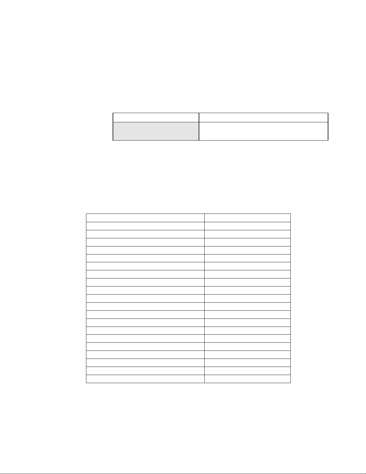
MIDI In port. To set the MMC address, go to Setup Menu 420, press Trim and set the appropriate
MIDI Device ID number for as required by the device transmitting the MMC messages to which
the MMR/MMP will respond. The range of available MIDI device ID’s is 1 to 127, with the
system default being 74.
01234567890123456789 20 position LCD character positions
420 MIDI Device Id Top: (Menu Item)
* 74 Bottom: (Encoding Type)
Supported MIDI Machine control messages are described in the next section of the documentation.
MMR/MMP MIDI Machine Control Protocol
All numerical values are hexadecimal, unless otherwise noted. For descriptions of the following
commands and responses, please refer to the MIDI Machine Control 1.0 specification, subtitled
MIDI 1.0 Recommended Practice RP-13, January 1992.
MMC Commands: Comments
01 STOP
02 PLAY
03 DEFERRED PLAY
04 FAST FORWARD
05 REWIND
06 RECORD STROBE ( RECORDER ONLY )
07 RECORD EXIT ( RECORDER ONLY )
09 PAUSE
0B CHASE ( requires time code input)
0D MMC RESET
40 WRITE
41 MASKED WRITE ( RECORDER ONLY )
42 READ
44 LOCATE
45 VARIABLE PLAY ( defaults to shuttle )
46 SEARCH ( defaults to shuttle )
47 SHUTTLE
4C MOVE
52 GROUP
54 DEFERRED VARIABLE PLAY
Note: In all velocity commands and information fields, the MMR-8 and MMP-16 support
multiples of play speed from +/- 20 with 1/1024 fractional resolution.
TASCAM MMR-8/MMP-16 Version 3.0 Owners Manual Update 9
Page 10

MMC Information Fields
Hex Field Read / Read Write
01 SELECTED TIME CODE r
02 SELECTED MASTER CODE r
03 REQUESTED OFFSET RW
04 ACTUAL OFFSET r
05 LOCK DEVIATION r
08 GP0/LOCATE POINT RW
09 GP1 RW
0A GP2 RW
0B GP3 RW
0C GP4 RW
0D GP5 RW
0E GP6 RW
0F GP7 RW
21 short SELECTED TIME CODE r
22 Short SELECTED MASTER CODE r
23 Short REQUESTED OFFSET r
24 short ACTUAL OFFSET r
25 short LOCK DEVIATION r
26 short GENERATOR TIME CODE r
28 Short GP0/LOCATE POINT r
29 Short GP1 r
2A Short GP2 r
2B Short GP3 r
2C Short GP4 r
2D Short GP5 r
2E Short GP6 r
2F Short GP7 r
45 TIME STANDARD RW
48 MOTION CONTROL TALLY r
49 VELOCITY TALLY r
4C RECORD MODE RW ( RECORDER ONLY )
4D RECORD STATUS r ( RECORDER ONLY )
4E TRACK RECORD STATUS r ( RECORDER ONLY )
4F TRACK RECORD READY RW ( RECORDER ONLY )
50 GLOBAL MONITOR RW ( RECORDER ONLY )
51 RECORD MONITOR RW ( RECORDER ONLY )
53 TRACK INPUT MONITOR RW ( RECORDER ONLY )
58 CONTROL DISABLE RW
5A CHASE MODE r
RW - indicates read / write r - indicates read only
TASCAM MMR-8/MMP-16 Version 3.0 Owners Manual Update10
Page 11

MMR-8 MMC Signature
2E, count = n
01, 00, 00, 00, vi vf va vb
14, <count_1>
7E, 5D, 00, 00, 00, c0 c1 c2 c3 c4
00, 00, 00, 00, 00, c5 c6 c7 c8 c9
71, 31, 50, 00, 00, c10 c11 c12 c13 c14
00, 00, 00, 00, 00, c15 c16 c17 c18 c19
14, <count_2>
7E, 7E, 03, 00, 00, r0 r1 r2 r3 r4
7E, 7E, 03, 00, 00, r5 r6 r7 r8 r9
25, 66, 0F, 28, 04, r10 r11 r12 r13 r14
00, 00, 00, 00, 00, r15 r16 r17 r18 r19
MMP-16 MMC Signature
2E, count = n
01, 00, 00, 00, vi vf va vb
14, <count_1>
7E, 5D, 00, 00, 00, c0 c1 c2 c3 c4
00, 00, 00, 00, 00, c5 c6 c7 c8 c9
71, 31, 50, 00, 00, c10 c11 c12 c13 c14
00, 00, 00, 00, 00, c15 c16 c17 c18 c19
14, <count_2>
7E, 7E, 03, 00, 00, r0 r1 r2 r3 r4
7E, 7E, 03, 00, 00, r5 r6 r7 r8 r9
25, 66, 0F, 28, 04, r10 r11 r12 r13 r14
00, 00, 00, 00, 00, r15 r16 r17 r18 r19
MIDI Inquiry Message
General Response: F0 7E <channel> 06 02 mm ff ff dd dd ss ss ss ss F7
The MMR-8 and MMP-16 engineering development is done by TimeLine Vista, Inc. The MIDI
inquiry response codes are therefore those of TimeLine and not TASCAM.
The MMR-8 responds to a MIDI Inquiry message as follows:
mm TimeLine manufacturer system exclusive ID 00 00 49
ff ff Device Family Code 04 00 (LSB First)
dd dd Device Family Member Code 00 00 (LSB First)
ss ss ss ss Software Revision Level 00 00 xx xx (e.g. 03 00)
The MMP-16 responds to a MIDI Inquiry message as follows:
mm TimeLine manufacturer system exclusive ID 00 00 49
ff ff Device Family Code 04 00 (LSB First)
dd dd Device Family Member Code 01 00 (LSB First)
ss ss ss ss Software Revision Level 00 00 xx xx (e.g. 03 00)
TASCAM MMR-8/MMP-16 Version 3.0 Owners Manual Update 11
Page 12

Export As
01234567890123456789
20 position LCD character positi
Pro Tools Export As:
*MMR Project Name
01234567890123456789
20 position LCD character positi
Vol does not support
Bottom:(Error message – scroll
01234567890123456789
20 position LCD character positi
The Export menus in Version 3.0 allow for changing the name of a file when it is exported. After
pressing STO to initiate an Export, the Menu changes to allow entering a new name. It is also
possible to use Export As to make a copy of the Project (EDL) under a different name to the same
disk as the original file. Audio files will only be copied if they do not already exist in the proper
format on the target SCSI device.
Top: (menu name)
Bottom:(Enter new file name)
The MMR/MMP software only allows writing to WaveFrame or Macintosh HFS disk volumes. If
an attempt is made to Backup, Export, or Convert to a disk that is not in one of these formats, an
error message is shown:
File Top: (menu name)
format
to read entire message on LCD)
Rename
The MMR-8 and MMP-16 Version 3.0 software can rename any Project or Session file that
currently exists on a disk in the WaveFrame, Pro Tools or OMF/SDII formats. Rename of the Akai
and DEVA formats is not supported because the MMR and MMP do not write these file types. To
rename a file, access the file by pressing LOAD TRACK and scrolling to the name of the Project
to be renamed. While the name of the Project to be renamed is showing in the LCD, press
SHIFT+SLIP (backup) and scroll to the Rename menu item:
Rename project as: Top: (menu name)
*Project Name Bottom:(shows project name)
Use the Up/Down arrow keys or wheel to choose alphanumeric characters and the Left/Right
arrow keys move to the next or previous character. When the new name has been entered, press
STO to complete the process and write the new file name to the disk.
When Rename is used, the old file name will be overwritten and will no longer exist. To save a
copy of a Project under a new name while still retaining the original file with the original name, use
the Export menu to Export the file to the same disk, using the Export As function described
elsewhere in this document to create a copy of the file with a different name. The original file will
still exist under the original name.
TASCAM MMR-8/MMP-16 Version 3.0 Owners Manual Update12
Page 13

Serial Transport
01234567890123456789
20 position LCD character positi
01234567890123456789
20 position LCD character positi
The MMR-8 and MMP-16 have a 9-pin serial connector labeled TRANSPORT which acts as an
output for Sony P2 protocol serial commands. Software Version 3.0 activates this port so that the
MMR/MMP can act as a master controller for external serially controlled devices such as video
decks or the TASCAM DA-88 (with the SY-88 sync card).
To set the MMR/MMP to act as a serial master, go to Setup Menu 000 and set the Control Mode
to Serial Trans.
000 Control Mode Top: (menu name)
*Serial Trans Bottom:(shows control mode)
Once the Control Mode is set to Serial Trans, and MMR/MMP is ONLINE, the MMR/MMP
transport keys will send messages out of the TRANSPORT 9-pin connector. The attached serially
controlled device should respond to these messages. Once the external device has responded to a
transport message, the MMR will lock to the time code coming from the serial port of the device
being controlled.
Dailies Mode
The Version 3.0 software supports a new recording mode in the MMR-8 called Dailies Mode. To
activate Dailies Mode, go to Setup Menu 240 and toggle the menu selection to On.
240 Dailies Mode Top: (menu name)
*Off Bottom:(shows On or Off)
When Dailies Mode is on, and the MMR is ONLINE in Timecode Chase Mode, the MMR will
record audio on armed tracks whenever incoming time code is present. To initiate recording it is
necessary to arm at least one track , lock the MMR to external time code, and to press REC (or
PLAY + REC) to put the MMR-8 into the record state. When time code stops, the MMR-8
transport will stop, but the unit will remain in a record ready state until time code is received again.
When valid time code is again present, the MMR will automatically locate to the incoming time
code position and go into record. All files will be “stamped” with the time code location at which
the recording is made.
Dailies Mode is designed to facilitate the recording of production sound reels (“Dailies”) which are
typically recorded with discontinuous time code (and time code breaks) using a Nagra or other field
recorder. This allows production sound to be transferred into the MMR with proper time code
location information with a minimum of user intervention in the process. Once in the MMR, audio
can also be Exported to WaveFrame, OMF, or Pro Tools formats for sound editing.
TASCAM MMR-8/MMP-16 Version 3.0 Owners Manual Update 13
Page 14

Varispeed
01234567890123456789
20 position LCD character positi
01234567890123456789
20 position LCD character positi
The Varispeed control mode is implemented in Version 3.0 software. This function allows
playback of audio over a range of speeds from 88.5% to 104.33% of nominal play speed. The
precise speed can be set in increments of .1% over the entire range. To use the Varispeed function,
go to Setup Menu 000 and choose Varispeed as the Control Mode.
000 Control Mode Top: (menu name)
*Varispeed Bottom:(shows control mode)
To set the precise speed of playback, go to Setup Menu 006 and use the wheel or up/down arrows
to select the desired play speed.
006 Varispeed Rate Top: (menu name)
*100% Bottom:(range 88.5% to 104.3%)
This function works by changing the sampling rate of the unit and this is reflected in the sample
rate of the digital audio output stream from the MMR/MMP, which will vary according to the
speed set in this menu. This is different from the jog/shuttle mode because that mode produces a
constant sample rate output while scrubbing audio off speed. Note that the Varispeed Mode is
mutually exclusive with Time Code Chase or Biphase Chase and thus the unit cannot be
synchronized to an external source while in this mode. To instantly return to the default of 100%
(nominal speed), go to Setup Menu 006, press Trim, then press SHIFT + CLR.
Audio File Time Stamp Support
Version 3.0 adds a time code “stamp” as an attribute of all recorded files. This time code stamp
represents the time code location of the MMR unit when the recording was made. This data is now
recorded as part of the audio file data. This information will be retained when files are Backed Up,
Converted, or Exported to a different format. Many Digital Audio Workstations can use this
information to place audio at its recorded time code location for editing.
New SCSI Driver
The software code which controls the operation of the MMR/MMP SCSI disk interface, known in
engineering parlance as the “SCSI Driver” has been completely re-written for Version 3.0. This
has been done to allow more precise control of certain SCSI disk operations and to improve system
performance when dealing with very densely edited material. Changes to MMR/MMP operation
caused by this new SCSI Driver are outlined below.
No need to restart after low format
In previous software versions, performing a Low Format (Setup Menu 711) would require a
system reboot before the drive could be initialized or another drive used. In Version 3.0, the Low
Format process does not interfere with normal operation after the volume has been formatted.
TASCAM MMR-8/MMP-16 Version 3.0 Owners Manual Update14
Page 15

Mount volumes not present at startup
Prior to Version 3.0, all SCSI volumes to be used had to be present when the MMR/MMP booted
or they could not be recognized by the system. This has now changed so that SCSI devices which
may have been powered off or otherwise not present when the system was booted will be re-polled
and mounted even if they are added after the system is in operation. This applies especially to the
internal Kingston drive enclosure in the MMR/MMP unit. It is no longer necessary for a drive to
be present in the Kingston drive bay when the system is booted. A drive can be plugged in to the
Kingston bay and spun up after system boot up and it will be recognized by the system.
It is not a good idea to plug SCSI devices into the SCSI port on the back of the MMR while the
drive or the MMR/MMP system is on. This is true of any computer and any SCSI device. SCSI
Devices which are physically attached but not powered on or external Kingston or other removable
carriers which have no drive currently in place when the system boots will now be able to have
their volumes mounted once they are powered on and a drive is present.
No performance loss after spin down/spin up
An intermittent problem in previous software versions would sometimes result in a noticeable loss
of drive performance after a drive had been spun down and then spun back up, or a new drive
volume mounted. In Version 3.0 this can no longer occur, and spinning a drive down or changing
drives in the removable Kingston drive bay causes no degradation of performance.
Performance improvements
Version 3.0 provides a general increase in SCSI performance. This is especially noticeable for
slower media such as Magneto-Optical drives, and for 16 channel 24-bit performance on the
MMP-16 or other types of very high bandwidth demand uses which can stress the system.
Change in WaveFrame UFN Generation
Unique File Number generation for WaveFrame audio files has been changed to include the unit
serial number as part of the UFN generation. This makes it impossible for files created on different
machines at precisely the same instant to have the same UFN. A second change is that the
WaveFrame UFN is retained for sound files copied as part of a WaveFrame project Backup.
Punch In/Out Performance
The response time of the MMR/MMP system to a manual punch in/out command has been
substantially improved in Version 3.0. Programmed punches (using the Loop Record function or a
programmed punch from a Lynx KCU or Serial edit controller) are frame and sample accurate,
with a delay of 3 frames (100ms).
TASCAM MMR-8/MMP-16 Version 3.0 Owners Manual Update 15
Page 16

TapeMode Project Length
TapeMode is a special way of recording on the MMR-8 which creates a single audio file for each
track of the project. Punching in and out on a track when in TapeMode does not create new audio
files on the disk, it merely adds the new audio data to the existing track’s audio file.
Setup Menu 231 on the MMR-8 is a new setting which defines a maximum Project length for
projects created using TapeMode. The default value for this item is 00:10:00:00 (ten minutes).
01234567890123456789 20 position LCD character positions
231 TapeMode Length Top: (Menu Item)
*00:10:00:00 Bottom: (Project Maximum Length)
It is recommended that users always set a TapeMode Length when using TapeMode.
TapeMode works differently for Pro Tools files than with WaveFrame files due to inherent
differences between the WaveFrame and Macintosh HFS disk file systems. An advantage of the
WaveFrame file system is that it allows a single file to have "holes" in it. This means when using
TapeMode with WaveFrame format, a punch in at some point that is past the place where any
recording has taken place before will not automatically allocate all of the disk space between the
beginning of the file and the point of the punch. In practical terms this means you could have 10
minutes of disk space left and still be able to punch in at 2 hours on a project with a 1 hour start
time if you want.
The Macintosh Hierarchical File System has no provision for "holes" in a continuous file the way
the WaveFrame file system does. If, for example, you punch in at 3 hours on a ProTools
TapeMode Session, all disk space from the beginning of the project to the 3 hour mark is
automatically allocated to the Session. This is one of the main reasons for addition of the
TapeMode Length menu item in Version 3.0. By constraining the length of a TapeMode project,
users are prevented from punching in to a ProTools Session past the end of the project and
accidentally allocating disk space which will not be used.
Note: The TapeMode Length data is not stored as an attribute of the Project, Session, or
Composition, but can be saved as part of the MMR User settings (Setup Menu 900).
Record Punch Change
Record punch in during Timecode Chase and Biphase Chase control modes or when resolved to
video now waits for locked status.
In/Out Recalculation Change
The In and Out time code registers are now recalculated when the sample rate is changed to insure
that they are aligned with the same audio samples as they were before the rate change.
TASCAM MMR-8/MMP-16 Version 3.0 Owners Manual Update16
Page 17

Set SCSI Record Volume
A new Setup Menu (701) makes it easier to specify a target SCSI volume for recording. This menu
has a range of 0 to 7. If no drives are mounted, this menu will show None to indicate no drive
volumes are present.
01234567890123456789 20 position LCD character positions
701 Record Disk Top: (Menu Item)
*SCSI Disk 0 Bottom: (Choose SCSI record volume)
To set the record device, press the TRIM key then choose a valid SCSI device ID using either the
up/down arrow keys or the wheel. If a SCSI drive ID is chosen which is not currently mounted and
available, the system will show a warning that this is a non existent volume. Press CLR to cancel
the warning and return to the Record Disk setting.
01234567890123456789 20 position LCD character positions
701 Record Disk Top: (Menu Item)
Non Existent Volume Bottom: (Choose SCSI record volume)
Show Project Format
A new feature of Version 3.0 shows the file format of any project available for loading on the
MMR/MMP. This indicated by a two letter code in brackets at the end of the project name.
01234567890123456789 20 position LCD character positions
File Top: (File Item)
Rons Project [PT] Bottom: (Indicates Pro Tools project)
The codes used for currently supported file types are:
[PT] Pro Tools
[WF] WaveFrame
[AK] Akai
[DV] DEVA (Broadcast Wave)
[OM] OMF/SDII
Show Track Format, Drive ID
Once a track has been loaded, pressing VIEW TRACK will show the name of the selected track
followed by brackets around a number which indicates the drive ID and format type of the track.
01234567890123456789 20 position LCD character positions
Track Contents: Top: (Track contents)
1 MMR Trk1_00837 [0,PT] Bottom: (Indicates drive ID and Format for track)
TASCAM MMR-8/MMP-16 Version 3.0 Owners Manual Update 17
Page 18

Delete and Disk Cleanup for Macintosh Volumes
The Project Delete function (accessed by using SHIFT + LOAD TRACK) and the Disk Cleanup
function (Setup Menu 720) now work for Macintosh HFS disks in Version 3.0. The Delete
command will Delete the selected Session or OMF file from a Macintosh volume. The Disk
Cleanup command will delete all Sound Designer II files that are not being referenced by a Pro
Tools Session or an OMF Composition. This command will also delete all linear fade files created
by a ProTools Session. Users should make sure there are no other SDII files that they wish to keep
(such as raw SDII sound libraries not referenced by an EDL) on a Macintosh disk before using this
command. Warning: this command cannot be undone.
Show Mounted SCSI Devices
Setup Menu 790 shows a list of SCSI ID numbers for all mounted SCSI drives. This is an
information display only, and has no parameters which can be set by the user.
01234567890123456789 20 position LCD character positions
790 Drives Mounted Top: (Menu Item)
*0,2,3 Bottom: (list of drives)
If no drives are mounted, the display will indicate “None”.
01234567890123456789 20 position LCD character positions
790 Drives Mounted Top: (Menu Item)
*None Bottom: (no drives mounted)
Clip LED Display Option
Setup Menu 522 allows for setting whether the Clip LED indicator will show clipping only for
record tracks or for both record and playback tracks. This feature was requested so that mixers
using the MM-RC will not be bothered by having the Clip LED over the REC key indicate level
clipping when the clipping occurs only on a playback track, not on a track which is in record.
01234567890123456789 20 position LCD character positions
522 Clip LED on Play Top: (Menu Item)
* Off Bottom: (choose On or Off)
To see a clipping indication at all times when any track (whether in record or playback) clips, set
the value of this menu to Off. To only show clipping for tracks which are in playback, set the value
of this menu to On.
Pro Tools Performance
The speed of mounting Macintosh volumes with a large number of audio files, OMF Compositions,
or Pro Tools Sessions has been dramatically improved.
TASCAM MMR-8/MMP-16 Version 3.0 Owners Manual Update18
Page 19

Project Attributes Not Changed in TapeMode
Changing the sample or fame rate will not change the sample or frame rate attributes of a
WaveFrame Project or a Pro Tools Session while the system is in TapeMode. These attributes are
created when the Project or Session is first created. If the sample or frame rate is changed while the
record mode is set to non-destructive, the file attributes are changed and the new sample rate or
frame rate will be set when the file is loaded again.
Commit Track Slip
A new Setup Menu (250) allows any track slip to be committed as an edit. The Track Slip function
on the MMR/MMP works by changing the value of a track offset register. This slip offset is
volatile and will be cleared when a new Project or track is loaded. When a track slip is committed
using Menu 250, the amount of the slip is incorporated into an edit operation which changes the
track EDL to reflect the new time code location for all audio events on the track. This change is
automatically saved to disk for WaveFrame and Pro Tools projects (not for other formats since
they can not be saved to disk) and the EDL is instantly updated.
01234567890123456789 20 position LCD character positions
250 Slip Commit Top: (Menu Item)
* All Tracks Bottom: (Allows choice of tracks)
The Slip Commit menu allows for committing all tracks which have a slip offset, or of choosing
only a specific track. The default value is to commit all track slips.
Meter Interface
Version 3.0 adds support for the MMU-16 Meter unit. Setup Menu 550 (Rmt Meter Source)
allows a choice of MMR Bus or Local as the source of the data for the remote meters. When set to
MMR Bus, the meter data is communicated via the MMR Bus and the UI/B board to an MMRC remote so that the MM-RC can send digital meter data to an MMU-16 connected to the MMRC. The MM-RC can thus direct meter data to the MMU-16 for any currently selected
MMR/MMP unit which can be addressed by the MM-RC. When set to Local, the meter data is
sent directly out of the UI/B board’s remote control connector on the back of the MMR/MMP unit
to an MMU-16 connected directly to the unit.
01234567890123456789 20 position LCD character positions
550 Rmt Meter Source Top: (Menu Item)
* MMR Bus Bottom: (Allows choice meter source)
External Resolve Changes
Video resolve is now supported while the sample clock is locked to the external sample source.
This permits various combinations of external word clock (or AES/EBU sample clock) with
external frame references (Video/Lynx/TC/Biphase). This causes the "EXT RSLV" LED to
illuminate, indicating that external resolve is required to guarantee stable sync.
TASCAM MMR-8/MMP-16 Version 3.0 Owners Manual Update 19
Page 20

Improve Lock Speed to External Clocks
Lock to an external digital clock signal (AES or Word Clock) has been dramatically improved and
stable lock to external digital clock signals now happens immediately. If the MMR/MMP sample
rate is 48kHz, or one of the 48kHz pull up/pull down values, it will lock to an external sample
clock in the range 46008 Hz to 50078 Hz. If the MMR/MMP rate is centered around 44.1kHz, the
lock range is 37566 Hz to 46008 Hz.
ONLINE Function Change
Taking an MMR/MMP unit offline when in Biphase Chase mode will cause the MMR/MMP to
ignore incoming Biphase and then set a new sync interlock point at the current position when the
unit is put back ONLINE. A new function in Version 3.0 adds a SHIFT + ONLINE command to
return the machine to a previously established sync point when in Biphase Chase mode. This means
that the system now will keep track of position on the Biphase input even while offline.
To put the unit back ONLINE at the previously established sync point (the interlock location that
existed prior to when the unit was taken offline), press SHIFT + ONLINE. To reset the sync point
to be the current time and set the interlock to the current position of the biphase master, simply
press ONLINE as in all previous versions of the MMR/MMP software.
Serial Editor Port Changes
A number of changes have been in Version 3.0 to the operation of the 9-pin serial Editor port.
These are detailed in this section of the documentation.
Record Ready Tallies
Record ready tallies issued over the 9-pin serial Editor port now include tracks armed at the MMR8 front panel or MM-RC, and not just those tracks armed by serial command. This allows an
external Serial device to know when a track has been armed for recording, regardless of the source
of the track arm command.
Sony P2 Chase and Offset Commands
Sony P-2 protocol Chase and Offset commands are now accepted by the MMR/MMP. Setup Menu
404 allows for setting the chase source to either Timecode, Biphase, or Disabled.
Serial Editor Port Active When Not ONLINE
The MMR/MMP unit will follow transport, track arm, and record commands given on the 9-pin
serial Editor port even when the unit is not ONLINE.
Automatic ONLINE
The MMR/MMP unit will now automatically be placed in the ONLINE state when placed in
Chase via the serial 9-pin Editor port.
TASCAM MMR-8/MMP-16 Version 3.0 Owners Manual Update20
Page 21

Local Machine Response to Serial Record Commands
Serial record arm and punch in/out commands are now honored locally on each machine,
regardless of whether it is acting as an MMR Bus slave or master machine. These commands are
not propagated across the MMR Bus to other machines, and serve only to activate the machine to
which the Serial control device is directly connected.
Program Speed Play
The MMR/MMP now responds in a very controlled way to Sony Program Speed Play commands.
Previous version used a jog/shuttle mode. The status response during Program Speed Play now
indicates Play mode, with the VAR bit set in byte 2 of the Sony Status array.
Editor Mode Operation Without Video Reference
The Editor Control Mode (set via Setup Menu 000) will no longer force the Frame Reference
(Setup Menu 001) to Video, and will allow operation of the MMR/MMP without a valid video
sync reference source attached to the MMR/MMP. It is highly recommended to have such a source
when operating in this mode, and to set the Frame Reference Setup Menu to Video, but the system
will no longer require it and will allow operation even if no such source is detected. If the
controlling device is synchronizing the MMR/MMP via the serial Editor port, it is essential to
provide a video reference to insure correct operation and synchronization.
Hybrid Protocol on Serial Editor Port
The MMR/MMP internal communication protocol (TimeLine’s Hybrid Protocol) can now be
accessed via the serial 9-pin Editor control port. This is most useful for companies which want to
exercise remote control (from some other device) of MMR/MMP features not supported via any of
the other standard remote interfaces. Requests for Hybrid Protocol information and documentation
should be directed to the Marketing Director at TimeLine Vista, Inc. at (760)761-4440, or via
email request to: TimeLine@digaudio.com.
Parallel I/O Changes
Version 3.0 makes some changes to the operation of the MMR/MMP parallel control ports. These
changes are detailed here.
Dedicated Record/Rehearse ON/OFF pins
Two previously unused pins have been activated to initiate Record ON and Record OFF commands
on the Parallel Transport port. The pins activated for these commands are pin #1 for Record ON
and pin #2 for Record OFF. These pins differ from the existing Record pin in that they have no
connection to the MMR motion control unit, do not require the concurrent activation of the Play
pin, and will not affect the ONLINE status of the MMR-8. Rehearse mode may be achieved by
holding the Preview pin (pin #36) low while pulsing the Record ON pin (pin #1). The operation of
the existing Record pin (pin #35) has not changed. A chart showing the complete pin assignments
for the Parallel Tracks and Parallel Transport connectors is given at the end of this document.
TASCAM MMR-8/MMP-16 Version 3.0 Owners Manual Update 21
Page 22

Lock Tally Out
A system lock tally is now provided on pin #28 of the Parallel Transport port. This active low lock
tally signal is provided when the system transport achieves lock status as indicated by the >L
indication in the LCD window and illumination of the LOCK LED.
Record Punch to Local Only
Record punch in and out commands will only be honored on the machine to which they are
directed, and will not cause other machines which may be connected via the MMR Bus to respond
to these commands. This means punching via the parallel port on the MMR Bus Master machine,
will only affect that machine and will not propagate via the MMR Bus to any Slave machines.
Bug Fixes:
The following software bugs have been fixed in Version 3.0.
Slip In/Out in Feet/Frame
The Edit commands and Slip In/Out function (accessed on the front panel by pressing SHIFT +
MON) now work properly when the display style is feet and frames and a local zero offset
(equating 0 feet and frames with a time code offset amount) is stored in the time register.
Store Slip In/Out amount
Storing a numeric value to the Slip In/Out key on the MM-RC remote will cause the selected audio
material (any audio on the selected tracks between the In and Out register time code positions) to
be slipped by that amount. The Slip In/Out function is accessed on the front panel of the
MMR/MMP by pressing SHIFT + MON, but storing a number on the front panel did not work
properly in previous versions of the software. In Version 3.0, this function now works properly on
the front panel of the MMR/MMP by pressing STO + SHIFT + MON to enter a time value for the
Slip In/Out operation.
All Safe for MMR Bus Slave
A bug in previous software versions allowed the MMR-8 to ignore its All Safe setting (Setup
Menu 201) when receiving a Record command from an MMR Bus master. This has been fixed in
Version 3.0, and the All Safe setting is always honored.
Fix “Busy” Exit
In Version 3.0 of the MMR/MMP software, the system keeps track of incoming biphase signals
even while the system is “busy”. This most typically occurs if a track is slipped while the unit is
ONLINE in biphase chase mode. This fix insures that if any sync changes (track slip) are made
while incoming time code or biphase signals are present, the system will return to the proper sync
point when it emerges from the “busy” state.
TASCAM MMR-8/MMP-16 Version 3.0 Owners Manual Update22
Page 23

MMR-8 Setup Menus for Version 3.0
The following chart shows all MMR-8 Setup menus and parameters in Version 3.0. Note that *
indicates the default selection.
MENU # MENU NAME
000 Control Mode
001 Frame Reference
002 Sample Reference
003 Time Code Type
004 Sample Rate
006 Varispeed Rate 100% *
100 Sync Group
PARAMETERS
Local/MMR*
Time Code Chase
Biphase Chase
Serial Transport
Editor
Varispeed
Automatic*
Video
Automatic*
AES/EBU Input
Ext Wordclock
24/24
25/25
29.97/DF
29.97/NDF
30/DF
30/NDF*
42294 (44x23/25)
42336 (44x24/25)
44056 (44100-)
44100
44144 (44100+)
45938 (44x25/24)
45983 (44x25/23)
46034 (48x23/25)
46080 (48x24/25)
47952 (48000-)
48000*
48048 (48000+)
50000 (48x25/24)
50050 (48x25/23)
(range 88.5% to 104.3%)
1*
2
3
4
TASCAM MMR-8/MMP-16 Version 3.0 Owners Manual Update 23
Page 24

MENU # MENU NAME
110 MMR Bus Request
111 Ident Request
112 Ident Assigned
120 Lynx Bus
121 Lynx Address
122 Lynx V500 Mode
PARAMETERS
Master
Off*
Slave
Auto Assign*
01
(Range 01-100)
01*
(Range 01–100 read-only display)
Off*
Slave/KCU
Master
1*
Range: 0 through 127
Off*
On
200 Record Mode
201 All Safe
202 Record Key
203 Rehearse key
210 Loop Mode
211 Loop Record
212 Pre-Roll
213 Post-roll
220 Next/Prev Mode
221 Edit Sync Mode
230 TapeMode Start
Non-Destructive*
TapeMode
Off*
On
Record+Play*
Record
Rehearse+Play*
Rehearse
Play Repeatedly*
Play once and Cue
Play once and Stop
Repeat Record*
Record Once Only
Repeat w/Unload
00:00:05:00*
00:00:02:00*
Event*
Cue
Sync at In Point*
Sync at Playhead
01:00:00:00*
(Range 00:00:00:00 to 23:59:59:29)
231 TapeMode Length 00:10:00:00*
(Range 00:00:00:00 to 23:59:59:29)
TASCAM MMR-8/MMP-16 Version 3.0 Owners Manual Update24
Page 25

MENU # MENU NAME PARAMETERS
240 Dailies Mode
250 Slip Commit
300 Biph Frame Rate 24 fps*
301 Biph Pulse Rate 2 ppf
302 Biphase Input
400 Editor Device
401 Editor Auto EE
Off*
On
All Tracks*
Track 1
[lists all tracks through Track 8 on MMR-8, Track
16 on MMP-16]
Track N
25 fps
30 fps
4 ppf
10 ppf*
20 ppf
25 ppf
50 ppf
100 ppf
Biphase*
Tach + Dir
Tach + Inverse Dir
TASCAM MMR-8*
Sony PCM-7030
Sony BVU-950
Off*
On
402 Editor Edit Fld
403 Editor Trk Arm
404 Editor Chase
410 Parallel Trk Arm
420 MIDI Device Id
Auto*
Field 1
Field 2
Digital Audio*
Analog A1-A4
Local
Local [enbl=A1]
Local [enbl=A2]
Local [enbl=A3]
Local [enbl=A4]
Disabled *
Timecode
Biphase
Pulse (toggle)*
Pulse w/ Auto Rec
Hold
Hold w/ Auto Rec
Pulse In + Out
74*
(Range 1 to 127)
TASCAM MMR-8/MMP-16 Version 3.0 Owners Manual Update 25
Page 26

MENU # MENU NAME PARAMETERS
500 Input Source Analog*
Digital
Rate Converter
501 Auto Input Rec Only
Rec or Non-Play*
Rec or Rec-Ready
510 Crossfade 10 ms*
Range: 0 through 100
520 Meter Ref Level -20 dBFS*
Range: -15 through -24 dBFS
521 Meter Calibrate Off*
On
522 Clip LED on Play Off*
On
530 Reference Tone Off*
1kHz
540 Gapless Punchout On*
Off
550 Remote Meter Source MMR Bus*
Local
600 Digital In Ref Track 1*
3
5
7
602 Digital In Delay Internal*
Number of Samples (Range:1 through 255
Samples)
610 Digital Out Delay Internal*
Number of Samples (Range:1 through 255
Samples)
620 Rate Conversion Slow response*
Fast Response
TASCAM MMR-8/MMP-16 Version 3.0 Owners Manual Update26
Page 27

MENU # MENU NAME PARAMETERS
700 Disk Encoding WaveFrame 16-bit*
WaveFrame 24-bit
Pro Tools 16-bit
Pro Tools 24-bit
701 Record Disk SCSI Disk 0*
[Shows SCSI Disk ID Number (Range 0 to 7)]
None
710 Disk Initialize Press STO
711 Disk Low Format Press STO
720 Disk Cleanup Press STO
790 Drives Mounted [shows list in format: 0,1,2,3,4,5,6]
800 Project Name MMR Project*
810 Track Prefix MMR Trk*
900 Store Settings User 1
[through]
User 10
901 Recall Settings Default
User 1
[through]
User 10
Previous
910 Set MM:DD:YY Date: __:__:__
911 Set HH:MM:SS Time: __:__:__
912 Change Password Press STO
920 LED Brightness 8*
Range: 0 through 15
980 Serial Number Read – only display
990 Software Version Read – only display
995 Load Software Press STO key
TASCAM MMR-8/MMP-16 Version 3.0 Owners Manual Update 27
Page 28

MMP-16 Setup Menus for Version 3.0
The following chart shows all MMP-16 Setup menus and parameters in Version 3.0. Note that *
indicates the default selection.
MENU # MENU NAME
000 Control Mode
001 Frame Reference
002 Sample Reference
003 Time Code Type
004 Sample Rate
006 Varispeed Rate 100% *
100 Sync Group
PARAMETERS
Local/MMR*
Time Code Chase
Biphase Chase
Serial Transport
Editor
Varispeed
Automatic*
Video
Automatic*
AES/EBU Input
Ext Wordclock
24/24
25/25
29.97/DF
29.97/NDF
30/DF
30/NDF*
42294 (44x23/25)
42336 (44x24/25)
44056 (44100-)
44100
44144 (44100+)
45938 (44x25/24)
45983 (44x25/23)
46034 (48x23/25)
46080 (48x24/25)
47952 (48000-)
48000*
48048 (48000+)
50000 (48x25/24)
50050 (48x25/23)
(range 88.5% to 104.3%)
1*
2
3
4
TASCAM MMR-8/MMP-16 Version 3.0 Owners Manual Update28
Page 29

MENU # MENU NAME
110 MMR Bus Request
111 Ident Request
112 Ident Assigned
120 Lynx Bus
121 Lynx Address
122 Lynx V500 Mode
PARAMETERS
Master
Off*
Slave
Auto Assign*
01
(Range 01-100)
01*
(Range 01–100 read-only display)
Off*
Slave/KCU
Master
1*
Range: 0 through 127
Off*
On
210 Loop Mode
211 Loop Record
212 Pre-Roll
213 Post-roll
220 Next/Prev Mode
221 Edit Sync Mode
250 Slip Commit
300 Biph Frame Rate 24 fps*
301 Biph Pulse Rate 2 ppf
302 Biphase Input
Play Repeatedly*
Play once and Cue
Play once and Stop
Repeat Record*
Record Once Only
Repeat w/Unload
00:00:05:00*
00:00:02:00*
Event*
Cue
Sync at In Point*
Sync at Playhead
All Tracks*
Track 1
[lists all tracks through Track 8 on MMR, 16 on
MMP]
Track N
25 fps
30 fps
4 ppf
10 ppf*
20 ppf
25 ppf
50 ppf
100 ppf
Biphase*
Tach + Dir
Tach + Inverse Dir
TASCAM MMR-8/MMP-16 Version 3.0 Owners Manual Update 29
Page 30

MENU # MENU NAME
400 Editor Device
404 Editor Chase
420 MIDI Device Id
510 Crossfade 10 ms*
520 Meter Ref Level -20 dBFS*
522 Clip LED on Play Off*
530 Reference Tone Off*
550 Remote Meter Source MMR Bus*
PARAMETERS
TASCAM MMR-8*
Sony PCM-7030
Sony BVU-950
Disabled *
Timecode
Biphase
74*
(Range 1 to 127)
Range: 0 through 100
Range: -15 through -24 dBFS
On
1kHz
Local
610 Digital Out Delay Internal*
Number of Samples (Range:1 through 255
Samples)
710 Disk Initialize Press STO
711 Disk Low Format Press STO
720 Disk Cleanup Press STO
790 Drives Mounted [shows list in format: 0,1,2,3,4,5,6]
800 Project Name MMR Project*
810 Track Prefix MMR Trk*
900 Store Settings User 1
[through]
User 10
901 Recall Settings Default
User 1
[through]
User 10
Previous
910 Set MM:DD:YY Date: __:__:__
911 Set HH:MM:SS Time: __:__:__
TASCAM MMR-8/MMP-16 Version 3.0 Owners Manual Update30
Page 31

MENU # MENU NAME
912 Change Password Press STO
920 LED Brightness 8*
980 Serial Number Read – only display
990 Software Version Read – only display
995 Load Software Press STO key
PARAMETERS
Range: 0 through 15
Technical Notes
Now that a large number of MMR/MMP units are working in post production facilities around the
world, we have identified a few common problems encountered by users. This section discusses
some issues to be aware of when using the MMR-8 and MMP-16.
SCSI Setup
One of the most crucial factors in using external drives with the MMR/MMP is the quality of the
SCSI hardware used. The most important factors to be aware of are the following:
1) Use only high quality SCSI cables which have separate ground wires for each data wire. A
good rule is the cable should be closer to the thickness of a thumb than a pencil.
2) Be sure the external SCSI device is terminated using an active SCSI terminator.
3) Use short SCSI cable runs. This is especially important when using an external enclosure
supporting multiple Kingston SCSI bays. We recommend cable runs of 1 meter or less.
4) Use only disk drives that have been certified to work with the MMR/MMP. We are constantly
testing new drives for performance and suitability. The latest list of certified SCSI drives is
available on the TASCAM web site at http://www.tascam.com
MMR Bus Procedures
When multiple MMR/MMP units are connected to each other via the MMR Bus connector, it is
important to assign each unit a unique unit ID number using Setup Menu 111. If the Auto-assign
setting is used, this could cause confusion when a new unit is added to the bus, since the ID’s are
assigned based on unit serial numbers. This could cause a unit already on the bus to change ID
numbers, which might result in inadvertent changes to the MMR Bus sample rate or frame rate
settings. If units use only pre-assigned unit ID numbers, this cannot occur and new units can safely
be added to the bus without affecting units already on the MMR Bus.
TASCAM MMR-8/MMP-16 Version 3.0 Owners Manual Update 31
Page 32

Parallel Tracks and Parallel Transport Connector Pinout
(+5V)
DARLINGTON OUTPUT STAGE OF ULN2803A
MAX RATINGS: 50V @ 500MA
Connectors are 37-pin D male. I/O on connectors share same logical ground. Electrical characteristics are:
TYPICAL INPUT
VCC
10K
INPUT PIN
10K
1 2
74HC14
TYPICAL OUTPUT
OUTPUT PIN
2.7K
7.2K 3K
Tracks Tracks Transport
Switch Tally Switch Tally Switch Tally
1. Record ON
2. Record OFF
Locked 28.
1. Trk 1 Input 21. 9. Trk 1 Rec 29. 9. Online 29.
2. Trk 2 Input 22. 10. Trk 2 Rec 30. 10. Rewind 30.
3. Trk 3 Input 23. 11. Trk 3 Rec 31. 11. Rev Play 31.
4. Trk 4 Input 24. 12. Trk 4 Rec 32. 12. Stop 32.
5. Trk 5 Input 25. 13. Trk 5 Rec 33. 13. Play 33.
6. Trk 6 Input 26. 14. Trk 6 Rec 34. 14. FFwd 34.
7. Trk 7 Input 27. 15. Trk 7 Rec 35. 15. Record 35.
8. Trk 8 Input 28. 16. Trk 8 Rec 36. 16. Preview * 36.
Pins Common to Both Connectors
19. +5VDC 20. GRD 37. GRD
*When preview is grounded, all record functions will invoke rehearse.
TASCAM MMR-8/MMP-16 Version 3.0 Owners Manual Update32
Page 33

TASCAM
TEAC Professional Division
MMR-8/MMP-16
Version 3.0 Update
TEAC CORPORATION 3-7-3, Nakacho, Musashino-shi, Tokyo 180, Japan Phone: (0422) 52-5082
TEAC AMERICA, INC. 7733 Telegraph Road, Montebello, California 90640 Phone: (213) 726-0303
TEAC CANADA LTD. 5939 Wallace Street, Mississauga, Ontario L4Z 1Z8, Canada Phone: 905-890-8008 Facsimile: 905-890-9888
TEAC MEXICO, S.A. De C.V Privada De Corina, No.18, Colonia Del Carmen Coyoacon, Mexico DF 04100 Phone: 5-658-1943
TEAC UK LIMITED 5 Marlin House, Marlins Meadow, The Croxley Centre, Watford, Herts. WD1 8YA, U.K. Phone: 01923-819699
TEAC DEUTSCHLAND GmbH Bahnstrasse 12, 65205 Wiesbaden-Erbenheim, Germany Phone: 0611-71580
TEAC FRANCE S. A. 17 Rue Alexis-de-Tocqueville, CE 005 92182 Antony Cedex, France Phone: (01) 42.37.01.02
TEAC BELGIUM NV/SA P.A. TEAC Nederland BV, Perkinsbaan 11a, 3439 ND Nieuwegein, Netherlands Phone: 0031-30-6048115
TEAC NEDERLAND BV Perkinsbaan 11a, 3439 ND Nieuwegein, Netherlands Phone: 030-6030229
TEAC AUSTRALIA PTY., LTD. 106 Bay Street, Port Melbourne, Victoria 3207, Australia Phone: (03) 9644-2442 A.C.N. 005 408 462
TEAC ITALIANA S.p.A. Via C. Cantù 5, 20092 Cinisello Balsamo, Milano, Italy Phone: 02-66010500
73236 Rev B
 Loading...