


Studio Konnekt 48
User’s Manual
English Version

IMPORTANT SAFETY INSTRUCTIONS
The lightning flash with an arrowhead symbol within an equilateral triangle is intended to alert the user to the presence of uninsulated “dangerous voltage”
within the product's enclosure that may be of sufficient magnitude to constitute a risk of electric shock to persons.
The exclamation point within an equilateral triangle is intended to alert the user to the presence of important operating and maintenance (servicing) instructions in
the literature accompanying the product.
1 Read these instructions.
2 Keep these instructions.
3Heed all warnings.
4Follow all instructions.
5 Do not use this apparatus near water.
6Clean only with dry cloth.
7Do not block any ventilation openings. Install in accordance
with the manufacturer's instructions.
8Do not install near any heat sources such as radiators, heat registers, stoves, or other apparatus (including amplifiers) that produce heat.
9Do not defeat the safety purpose of the polarized or grounding-type plug. A polarized plug has two blades with
one wider than the other. A grounding type plug has two blades and a third grounding prong. The wide blade or the third prong are provided for your safety. If the provided plug does not fit into your outlet, consult an electrician for replacement of the obsolete outlet.
10Protect the power cord from being walked on or pinched particularly at plugs, convenience receptacles, and the point where they exit from the apparatus.
11Only use attachments/accessories specified by the manufacturer.
12Use only with the cart, stand, tripod, bracket, or table specified by the manufacturer, or sold with the apparatus. When a cart is used, use caution when moving the cart/apparatus combination to avoid injury from tip-over.
13Unplug this apparatus during lightning storms or when unused for long periods of time.
14Refer all servicing to qualified service personnel. Servicing is required when the apparatus has been damaged in any way, such as cord or plug is damaged, liquid has been spilled or objects have fallen into the apparatus, the apparatus has been exposed to rain or moisture, does not operate normally, or has been dropped.
Warning!
•To reduce the risk of fire or electric shock, do not expose this apparatus to rain or moisture and objects filled with liquids, such as vases, should not be placed on this apparatus.
•This apparatus must be earthed.
•Use a three wire grounding type line cord like the one supplied with the product.
•Be advised that different operating voltages require the use of different types of line cord and attachment plugs.
•Check the voltage in your area and use the correct type. See table below:
Voltage |
Line plug according to standard |
110-125V UL817 and CSA C22.2 no 42.
220-230V CEE 7 page VII, SR section
107-2-D1/IEC 83 page C4.
240V BS 1363 of 1984. Specification for 13A fused plugs and switched and unswitched socket outlets.
•This equipment should be installed near the socket outlet and disconnection of the device should be easily accessible.
•To completely disconnect from AC mains, disconnect the power supply cord from the AC receptacle.
•The mains plug of the power supply shall remain readily operable.
•Do not install in a confined space.
•Do not open the unit – risk of electric shock inside.
Caution:
You are cautioned that any change or modifications not expressly approved in this manual could void your authority to operate this equipment.
Service
•There are no user-serviceable parts inside.
•All service must be performed by qualified personnel.
a

EMC / EMI & CERTIFICATE OF CONFORMITY
EMC/EMI
This equipment has been tested and found to comply with the limits for a Class B Digital device, pursuant to part 15 of the FCC rules.
These limits are designed to provide reasonable protection against harmful interference in residential installations. This equipment generates, uses and can radiate radio frequency energy and, if not installed and used in accordance with the instructions, may cause harmful interference to radio communications. However, there is no guarantee that interference will not occur in a particular installation. If this equipment does cause harmful interference to radio or television reception, which can be determined by turning the equipment off and on, the user is encouraged to try to correct the interference by one or more of the following measures:
•Reorient or relocate the receiving antenna.
•Increase the separation between the equipment and receiver.
•Connect the equipment into an outlet on a circuit different from that to which the receiver is
connected.
•Consult the dealer or an experienced radio/TV technician for help.
For Customers in Canada:
This Class B digital apparatus complies with Canadian ICES-003.
Cet appareil numérique de la classe B est conforme à la norme NMB-003 du Canada.
Certificate of Conformity
TC Electronic A/S, Sindalsvej 34, 8240 Risskov, Denmark, hereby declares on own responsibility that the following product:
Studio Konnekt 48
that is covered by this certificate and marked with CE-label conforms with following standards:
EN 60065 Safety requirements for mains (IEC 60065) operated electronic and
related apparatus for household and similar general use
EN 55103-1 Product family standard for audio,video, audio-visual and entertainment lighting control apparatus for professional use. Part 1: Emission.
EN 55103-2 Product family standard for audio, video, audio-visual and entertainment lighting control apparatus for professional use. Part 2: Immunity.
With reference to regulations in following directives:
73/23/EEC, 89/336/EEC
Issued in Risskov, September 2007
Mads Peter Lübeck
Chief Executive Officer
TABLE OF CONTENTS
INTRODUCTION |
APPENDIX |
Safety instructions . . . . . . . . . . . . . . . . . . . . . .a EMC/EMI & Certificate of Conformity . . . . . . . .b Table of contents . . . . . . . . . . . . . . . . . . . . . . .3 Introduction . . . . . . . . . . . . . . . . . . . . . . . . . . . .4 Setup notes . . . . . . . . . . . . . . . . . . . . . . . . . . .5 Computer requirements . . . . . . . . . . . . . . . . . .5
ASIO channel names . . . . . . . . . . . . . . . . . . .66 Signal flow . . . . . . . . . . . . . . . . . . . . . . . . . . .67 FAQ . . . . . . . . . . . . . . . . . . . . . . . . . . . . . . . .68 Shortcut keys . . . . . . . . . . . . . . . . . . . . . . . . .68 DICE background . . . . . . . . . . . . . . . . . . . . . .68 Firmware update & Reset to default . . . . . . . .69
OVERVIEW
Front panel overview . . . . . . . . . . . . . . . . . . . .6 Rear panel overview . . . . . . . . . . . . . . . . . . . . .8
CONTROL PANEL
Mixer page . . . . . . . . . . . . . . . . . . . . . . . . . . .10 Preset handling . . . . . . . . . . . . . . . . . . . . . . .15 Setup page . . . . . . . . . . . . . . . . . . . . . . . . . . .16 Bass management . . . . . . . . . . . . . . . . . . . . .20
SETUP EXAMPLES |
|
Studio recording & monitoring . . . . . . . . . . . . |
22 |
Bass management & integration . . . . . . . . . |
24 |
Integrator . . . . . . . . . . . . . . . . . . . . . . . . . . . .26
Konnekt WDM driver . . . . . . . . . . . . . . . . . . .29 System settings . . . . . . . . . . . . . . . . . . . . . . .30
Studio Kontrol Remote . . . . . . . . . . . . . . . . . .34 Studio Kontrol Remote page . . . . . . . . . . . . .38
Fabrik C Studio . . . . . . . . . . . . . . . . . . . . . . . .40
Fabrik R Studio . . . . . . . . . . . . . . . . . . . . . . . .52
Preset Handling . . . . . . . . . . . . . . . . . . . . . . .58
ResFilter . . . . . . . . . . . . . . . . . . . . . . . . . . . . .60
Tuner . . . . . . . . . . . . . . . . . . . . . . . . . . . . . . .64
b |
TC Electronic, Sindalsvej 34, DK-8240 Risskov – info@tcelectronic.com |
English Version |
Manual revision 1.0 |
3 |
|
|
|

INTRODUCTION
Studio Konnekt 48 offers a comprehensive array of professional features that make recording, mixing and monitoring a breeze. All essential recording tools are in one box including world-class DSP effects, a wealth of I/O options, speaker management and many other powerful tools to take your recordings to the next level.
Extensive I/O section with IMPACT II™ preamps
•4 Impact II™ mic preamps
•12 analog inputs, 12 analog outputs simultaneously
•High resolution input meter
•96 kHz ADAT (8 channels SMUX), word clock and S/PDIF
•24/24 channels simultaneously to/from DAW
•Digitally controlled analog main XLR outputs
•Dual headphone outs with individual level control and source
24/8 channel digital mixer with double precision summing
•Flexible 24/8 DSP mixer with total recall and DSP effects insert points
•No compromise routing for all outputs
•48-bit double precision summing on all mix busses with 56-bit internal processing
•Talkback with selectable dim setting and listen back feature
•Aux send busses with flexible output routing
Speaker management based on AIR™ technology
•Full featured bass management section based on AIR™ - Speaker Management Technology
•Full support for surround systems
•Individual speaker level and delay settings in 0.1 steps
•Selectable frequency crossover points
•Support for 3 speaker systems, individually configurable, selectable from the remote
World-class DSP effects
•4 simultaneous 4-band EQ, multiband compression channel strip and mastering effects based on TC System 6000 algorithms
•No compromise built-in reverb based on TC Electronic Reverb 4000 technology
•All plug-ins VST and AU compatible
•Intuitive guitar tuner
•ResFilter plug-in
•Assimilator Konnekt plug-in
•Hardware effects Integrator plug-in
Desktop remote control with integrated talkback microphone (optional)
•Full mixer at your hand
•Built-in talkback mic
•High resolution LED light ring
•Compact design
More
•DICE II JetPLL™ jitter elimination technology
•Clock recovery
•Expandable with all other Konnekt interfaces thru TC Near
Should this manual leave any of your questions unanswered, please use the TC Support service, which you can access via our website www.tcelectronic.com. Over a period of time, we will collect the most frequently asked questions and update the manual accordingly. Manual updates are available for download on our website in PDF format. The current manual revision number is found at the bottom of page 3.
SETUP NOTES
Unpacking
•Open the box from the top and remove cabling.
•Lift out Styrofoam insert, then using both hands lift out Studio Konnekt 48.
•Remove plastic bag from Konnekt.
•Inspect your Studio Konnekt 48 for signs of transit damage.
•In the unlikely event of this having occurred, inform the carrier and the supplier.
•Keep all the packaging if damage has occurred, as this will show evidence of excessive handling force.
•It is also a good idea to keep the packaging if possible for future transportation.
Check contents
The package should contain the following items:
•Studio Konnekt 48 audio interface
•Studio Kontrol 48 remote and cable (optional)
•FireWire cable
•CD with software etc.
•Safety Instructions
•Quick Start Guide
Computer Requirements
Mac OS X 10.4 Tiger or 10.5 Leopard
•PowerPC (1 GHz or faster) or Intel CPU
•512 MB RAM
•FireWire (IEEE 1394) port*
•OS X 10.4.1 or 10.5
Windows XP SP2 or Vista x32
•Pentium 4, 1.6 GHz or faster
•512 MB RAM
•FireWire (IEEE 1394) port*
•Windows XP or Vista 32 bit
* We recommend running Konnekt units on a dedicated FireWire bus. If your computer has one or more FireWire connections on the chassis they will typically run on the same FireWire bus. You may connect the Konnekt to one of these. If you intend to run more FireWire devices simultaneously, such as e.g. an external hard drive, we recommend running this device on a separate bus.
This would typically be on an installed FireWire PCI card. Note that such a FireWire PCI card typically has 3 ports but these also operate on a single bus.
Software installation
•Be sure that you have the latest software. Download the latest software from www.tcelectronic.com/software
•We recommend installing the software before connecting the Studio Konnekt 48.
•Refer to the Konnekt Installation Guide supplied in the package and on the Konnekt CD.
•If you are familiar with software installation procedures in general you may simply insert the accompanying CD-ROM in your computer’s CD drive and follow the instructions.
TC Near control panel
If Konnekt drivers are installed correctly you are able to open the TCNear control panel.
On Windows computers:
Press: Start/Programs/TC Electronic/TC Near
The TC Near can also be accessed via the Windows Control panel.
On Mac computers: /Applications/TC Near
You may also start the application from System Preferences.
4 |
5 |

FRONT PANEL
channel |
1 preamp |
|
|
|
channel 2 preamp |
|
|
|
channel 3 preamp |
|
|
|
channel 4 preamp |
|
|
phones 1 |
phones 2 |
|
|
|
|
|
|
|
|
|
|
|
master level |
|
|
power |
||||
|
|
|
|
|
|
|
|
|
|
|
|
|
|
|
|
|
|
|
|
|
|
|
|
|||||||||||||
|
|
|
|
|
|
|
|
|
|
|
|
|
|
|
|
|
|
|
|
|
ADAT |
SPDIF |
TOS |
|
MIDI |
|
FireWire |
|
|
valid |
|
48V |
|
|||
|
|
|
|
|
|
|
|
|
|
|
|
|
|
|
|
|
|
|
|
|
|
|
|
|
||||||||||||
|
|
|
-20dB |
|
|
|
-20dB |
|
|
|
-20dB |
|
|
|
-20dB |
|
|
|
|
|
1-8 |
1-2 |
1-2 |
3-4 |
IN OUT |
|
|
|
|
|
|
|
|
|
||
|
|
PAD |
|
|
PAD |
|
|
PAD |
|
|
PAD |
|
|
|
|
|
|
|
|
|
|
|
|
|
O |
|
|
|
|
OFF ON |
|
|||||
|
|
|
|
|
|
|
|
|
|
|
|
|
|
|
|
|
|
|
|
|
|
|
|
|
|
|
|
|
|
|
|
|
|
|
|
|
|
|
|
|
|
|
|
|
|
|
|
|
|
|
|
|
|
|
|
|
|
|
|
|
|
|
|
-3 |
|
|
|
|
|
|
|
||
|
|
|
|
|
|
|
|
|
|
|
|
|
|
|
|
|
|
|
|
|
|
|
|
|
|
|
-6 |
|
|
|
|
|
|
|
||
|
|
|
|
|
|
|
|
|
|
|
|
|
|
|
|
|
|
|
|
|
|
|
|
|
|
|
-12 |
|
|
|
|
|
|
|
||
|
|
|
|
|
|
|
|
|
|
|
|
|
|
|
|
|
|
|
|
|
|
|
|
|
|
|
-24 |
|
min |
|
max |
|
|
|
||
|
|
min |
max |
|
min |
max |
|
min |
max |
|
|
max |
|
|
|
|
|
|
|
|
|
|
|
-40 |
|
|
|
|
|
|||||||
mic/inst input |
|
gain |
trim |
mic/inst input |
|
gain trim |
mic/inst input |
|
gain trim |
mic/inst input |
|
gain trim |
(ch3-4) |
(ch11-12) |
|
1 |
2 |
3 |
4 |
5/6 |
7/8 |
9/10 11/12 dB |
|
|
output |
|
studiokonnekt 48 |
|||||||||
|
|
|
|
|
|
|
|
|||||||||||||||||||||||||||||
IMPACT II technology |
|
IMPACT II technology |
|
IMPACT II technology |
|
IMPACT II technology |
|
|
|
|
|
|
|
|
|
|
|
|
|
|
||||||||||||||||
|
|
|
|
|
|
|
|
|
|
|
|
|
|
|
|
|
|
|
|
|
|
|
|
|
|
|
|
|
|
|
|
|
|
|
|
|
|
|
|
|
|
|
|
|
|
|
|
|
|
|
|
|
|
|
|
|
|
|
|
|
|
|
|
|
|
|
|
|
|
|
|
|
|
1Mic/Inst ch1-4 on combo XLR/Jack
Combo XLR/jack inputs. Both XLR and 1/4 inch jack can be used with this connector type.
The XLR connection (balanced)
Connect a microphone and you connect directly to the input of the IMPACT ™ mic preamps.
-For condenser microphones phantom power must always be activated. (see also #10 on the following page). It is generally no problem to use dynamic microphones in combination with phantom power.
-The Input LEDs on meters 1-4 indicate the level of the input signal. If the red O dB LED (overload) is lit, your signal is too “hot” and you should reduce the input gain using the GAIN TRIM potentiometer and/or the the PAD/-20 dB switch for that channel.
The 1/4 jack connection
reamp


 -20dB
-20dB
PAD
The 1/4 “jack part” of the connector is a high quality unbalanced Hi-Z circuit that is designed especially for direct connection of a passive guitar pick-up system (e.g. Strat-type) directly. If you want to connect balanced equipment using TRS jacks you should connect via the line inputs on the rear panel.
2Pad selector
The PAD selector can attenuate the input sensitivity by 20 dB. If you cannot attenuate the signal sufficiently using the GAIN/TRIM knob you should use the -20 dB position. This is typical when connecting line-level instruments.
3Gain/Trim
Use this control to set the appropriate input level. (see previous paragraph).
4Phones 1/Phones 2
Individual level control for phones output 1 and 2.
5Headphones connection
Two set of headphones may be connected for monitoring. Each headphones output has its own level control. It is also possible to set up an individual mix for each headphones output via aux 1 on the mixer page. Please refer to the description of the mixer page.
Warning!
Excessive sound pressure from earphones and headphones can cause hearing loss.
FRONT PANEL
6Meters
ADAT |
SPDIF |
|
TOS |
|
MIDI |
|
|
FireWire |
||||||||||
|
|
|
|
|||||||||||||||
1-8 |
1-2 |
|
1-2 |
3-4 |
|
IN OUT |
|
|||||||||||
|
|
|
|
|
|
|
|
|
|
|
|
|
|
|
|
|
|
O |
|
|
|
|
|
|
|
|
|
|
|
|
|
|
|
|
|
|
|
|
|
|
|
|
|
|
|
|
|
|
|
|
|
|
|
|
|
-3 |
|
|
|
|
|
|
|
|
|
|
|
|
|
|
|
-6 |
|||
|
|
|
|
|
|
|
|
|
|
|
|
|
|
|
-12 |
|||
|
|
|
|
|
|
|
|
|
|
|
|
|
|
|
-24 |
|||
|
|
|
|
|
|
|
|
|
|
|
|
|
|
|
-40 |
|||
1 |
2 |
|
3 |
|
4 |
|
5/6 |
7/8 |
9/10 11/12 dB |
|||||||||
|
|
|
|
|
|
|
|
|
|
|
|
|
|
|
|
|
|
|
Meters 1-4: Indicate the signal level present on the four inputs on the front panel.
Meters 5/6, 7/8, 9/10 & 11/12:
Indicates the signal preset on the line inputs on the rear panel. The meters always indicate the loudest/hottest signal of a channel pair.
Orange LEDs for ADAT, S/PDIF & TOS:
The orange LEDs refer to the lock state of the digital channels. Lock is acheived when the orange LEDs are lit.
Orange LEDs for MIDI:
LEDs for indication of MIDI In/Out.
7FireWire/Power LED indicator
When Studio Konnekt 48 is hooked up via FireWire, the blue LED in the right side of the display can indicate the following:
Steady lit: Connected to FireWire
Flashing: |
Uploading firmware, hardware error or |
|
FireWire communication error. |
Off: |
The Studio Konnekt 48 has no connection |
|
to the driver, maybe because the driver is |
|
not installed. |
8Valid LED
The master output level can be set using either the physical OUTPUT knob, via the Studio Kontrol remote or via the TC Near software mixer. If the green LED is
lit, the current position of the knob matches the actual output level.
9Output Level control
Sets the output level and overrules the level previously set by the Studio Kontrol remote.
10Phantom Power +48V
The XLR part of the Combo XLR/Jack connections features +48V phantom power when this switch is set to on. Phantom power is used to power line-drivers and condenser microphones.
There are three main types of microphones
Condenser microphone - phantom power required except for some models that use proprietary power supplies or built-in batteries. Please check the microphone's manufacturer specifications for details.
Electrodynamic microphone - phantom power is not required, but does not harm the microphone.
Ribbon microphones - phantom power could damage the microphone. Seek advice and documentation from the manufacturer of the microphone!
Only the condenser type requires phantom power. It is, however, no problem combining a condenser microphone in e.g. ch. 1, with a standard electrodynamic microphone (such as e.g. a Shure SM57) in ch. 2. Nor is it any problem to activate phantom power and use a condenser microphone to one input and connect a guitar using a 1/4 jack one
of the other inputs, as phantom power only concerns the XLR connections.
6 |
7 |
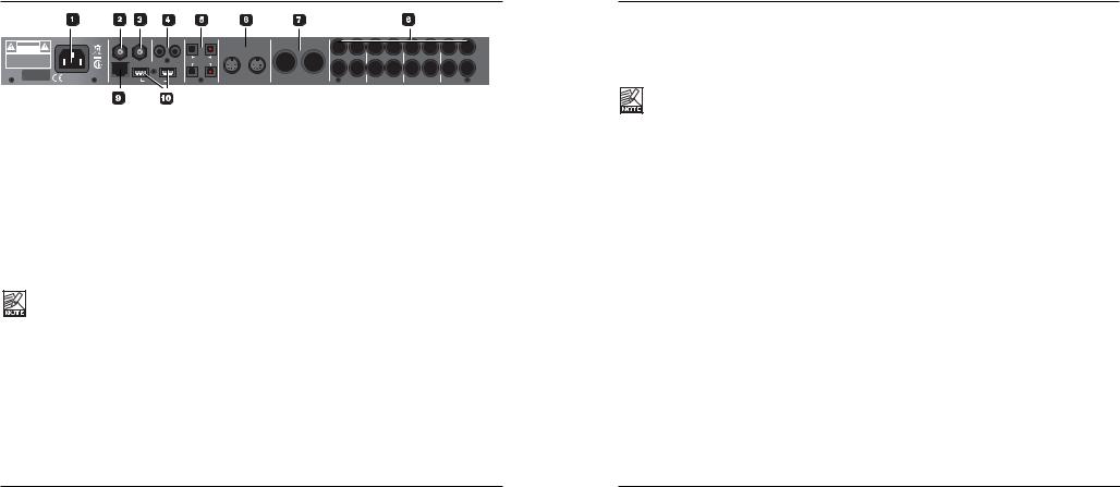
REAR PANEL |
|
|
|
|
|
|
|
|
|
|
|
|
|
|
|
|
|
|
|
|
100-240VAC~ 50-60Hz, 25W |
|
in |
WCK |
out |
in |
spdif out |
in |
opto out |
|
MIDI |
main stereo outputs |
|
|
|
|
|
|
|
CAUTION |
|
|
|
|
|
|
|
tos |
input |
output |
|
|
|
|
|
|
|
IN |
|
RISK |
DO NOT OPEN |
|
|
|
|
|
|
|
|
|
|
|
|
|
|
||||
|
OF ELECTRIC SHOCK |
|
|
|
|
|
|
|
|
|
|
|
|
|
|
|
|
|
|
|
|
|
|
|
|
|
|
|
3-4 |
|
|
|
|
|
|
|
|
|
|
|
WARNING |
|
|
|
|
|
|
|
adat 96k |
|
|
12 |
11 |
10 |
9 |
8 |
7 |
6 |
5 |
TO REDUCE THE RISK OF FIRE OR ELECTRIC |
|
|
|
|
|
|
|
|
|
||||||||||
SHOCK DO NOT EXPOSE THIS EQUIPMENT TO |
|
|
|
|
|
|
|
|
|
|
|||||||||
RAIN OR MOISTURE |
|
|
|
|
|
|
|
adat main |
|
|
|
|
|
|
|
|
|
|
|
AVIS: RISQUE DE CHOC ELECTRIQUE-NE PAS |
|
|
|
|
|
|
|
|
|
|
|
|
|
|
|
|
|
||
OUVRIR. |
|
|
|
|
|
|
|
|
|
|
|
|
|
|
|
|
|
|
OUT |
|
C |
US |
|
|
|
|
|
|
tos |
|
|
|
|
|
|
|
|
|
|
SERIAL NO. |
UL60065 |
|
|
|
|
|
|
1-2 |
|
|
|
|
|
|
|
|
|
|
|
|
EN/IEC 60065 |
|
|
|
|
|
|
|
|
|
|
|
|
|
|
|
|
||
DESIGNED AND |
|
|
|
|
|
|
|
|
|
|
DEVELOPED BY |
|
|
ch2|right |
ch1|left |
right left |
right |
left |
right |
left |
right left |
TC ELECTRONIC |
remote |
firewire |
1Power In
Mains power in. Studio Konnekt 48 uses a switchmode power-supply that accepts from 100 to 240VAC.
2Word Clock In
If you want to sync to an external word clock generator, connect it to WCK In using BNC connectors and select “Word Clock” as sync source on the System Settings page.
3Word Clock Out
Due to the DICE II chip, Studio Konnekt 48 can act as an excellent master clock generator for you setup. Connect via standard BNC plugs.
Beware that the Word Clock signal is not standardized. Some Word Clock receivers are known to fail when the peak-to-peak signal exceeds 3 Volt, and others are known to require at least 4 Volt, making it impossible to design a Word Clock driver guaranteed to operate with all receivers. Studio Konnekt 48 sends 1.7V PP.
4S/PDIF In/Out
Two channel, 24 bit 96 kHz digital in/out on S/PDIF. In addition to standard I/O it is possible to insert e.g. an external digital effects unit and use this as a send effect. (see setup examples)
5ADAT/Toslink I/O connectors
The optical connections carry either Toslink (optical S/PDIF) or ADAT signal.
ADAT:
-At normal sample rate, 8 channels of ADAT is carried on a single lightpipe. Use the MAIN connector.
-At double sample rate, 8 channels of ADAT is distributed on 2 lightpipe connectors. Use both the MAIN and the 96 kHz connections.
Toslink:
-Studio Konnekt 48 handles up to 4 input channels and 4 output channels of optical S/PDIF via Toslink.
6MIDI In/Out
Standard MIDI in/out. When Studio Konnekt 48 is used in stand-alone mode, MIDI out always acts as MIDI thru.
7Main Outputs
Digitally controlled true analog main outputs on balanced XLR.
Pin 1 Ground Pin 2 Hot Pin 3 Cold
8In/Out - additional channels
Input and outputs for channels 5 to 12 on balanced 1/4” jacks. The sensitivity for the line inputs can be set to -10 dBv or +4 dBu via the TC Near mixer page.
REAR PANEL
9Remote
RJ-45 connector for the Studio Kontrol remote (optional).
10FireWire connectors
IEEE 1394 connectors for connecting to a computer and/or linking multiple Konnekt units.
Before plugging the firewire connectors, make sure that plugs are positioned correctly.
8 |
9 |

CONTROL PANEL - MIXER PAGE |
|
CONTROL PANEL - MIXER PAGE |
|
|
|
1The Konnekt select tabs
Use the select tabs to switch between the Konnekt units in your setup and the System Settings page.
2Page tabs
Press to navigate between the mixer, setup, effects and tuner pages for the selected Konnekt unit.
3Add Channel
To keep an easy overview, not all channels are included in the default mixer layout. You may add any idle channel or channel pair via the Add Channel drop down menu. Channels that are already displayed in the mixer are “grayed out”. Channels that you can add are “solid”.
Max I/O mixer channels are 24 in / 8 out.
Removing a channel
Just as some channels can be added, the same channels can also be removed from the mixer when not used. Channels that can be removed have a small crossed square in the upper right corner. De-click this field to remove the channel from the mixer.
See also “Auto shrink”.
4Auto shrink
Unlike the “Remove Channel” function that allows you to completely remove an input channel that you no longer use, the Auto shrink function keeps all channels in the mixer, but collapses the graphics so that idle channels take up only a minimum of space.
Example:
In this example no cables are attached to the Studio Konnekt 48’s inputs and by pressing the AUTO SHRINK button we get this view:
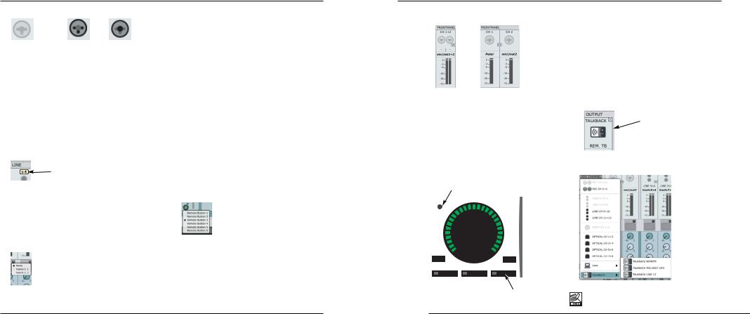
5Channel type
Indicates the channel type. Front panel, Digital, DAW, FireWire Output, Line etc.
6Ch1-4 auto-sensing input
Channels 1-4 connections on the front panel are autosensing. They automatically detect whether you have connected an XLR (microphone) or 1/4” jack (instrument), and this is displayed graphically.
10 |
11 |
CONTROL PANEL - MIXER PAGE
These are the options
Nothing connected |
Mic/XLR |
Inst./jack |
7Channel name - editable
This is the name of the mixer channel. Click once on the name using the mouse to edit the name.
All Channels
8Input Level meters & +4 dBu/-10 dBv sensitivity
The meters indicate the level of the signal present on the input channels. Best signal to noise ratio is achieved when the input signal only occasionally peaks at “0”. Adjust the level on the sending device while watching the meters.
You can toggle between a -10 dBv/+4 dBu sensitivity for line input channels by pressing:
9Clip LED (RED)
When the Clip LED is lit the signal is too hot. Reduce the level on the sending device to compensate.
10Channel inserts
Via the small drop down menu just below the channel meter you can insert one of the two Fabrik C channel strips or none.
11Sends
Each channel has three sends. One for the Fabrik R reverb and one for each of the two AUX sends. Each send can be set as a pre or post fader send.
The routing of the sends is set up on the Setup page.
12Pan/Balance
Fader for for left/right panning.
Press Ctrl+Shift and left mouse button to center.
13Mute/Solo
Press M to mute the channel output and S for soloing this channel.
14Channel Fader
Fader for the output of the channel.
15Fader assign - Studio remote control symbol
Some channels and functions are by default assigned to the Studio Kontrol remote. However, any channel added with the “Add Channel” function will appear with the remote control symbol. By pressing this symbol you are allowed to assign this channel to remote buttons 1-6 when the remote is in shift mode.
Press the remote symbol to access the drop down menu and select between Remote Button 1 to 6.
16Channel pair link/unlink
Press to link/unlink channels pairs. (see example on the following page)
CONTROL PANEL - MIXER PAGE
Example:
Linked Unlinked
17Monitor mix on/off
Tick of this box if you do not want to use the TC Near direct monitor feature.
Output section
18 Talkback function
Talkback microphone
P1 P2 P3
MIC |
|
PROG |
|
|
(P1-P3) |
The recording artist is typically placed in a recording room wearing headphones. The Talkback function allows you to communicate to the performer either via the small built in microphone located in the Studio Kontrol remote or via a microphone connected to Mic Input #4 or via Line In 12.
Selecting talkback microphone
The talkback microphone in the Studio Kontrol is selected per default.
•To change to either mic preamp #4 or line input 12 first close the talkback channel.
•Then press ADD CHANNEL and select talkback channel under “talkback”.
PANEL
M.MIX AUX1 EFFECT AUX2 TALK TUNER
Talkback button
It is only possible to select channels that currently are not in use.
12 |
13 |
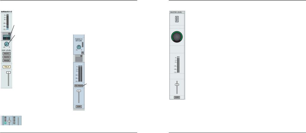
CONTROL PANEL - MIXER PAGE
Let us take a closer look at the Talkback mixer-channel
Channel naming and channel input metering is described previously.
Fabrik C studio - even on talkback
Even on the talkback channel you can insert one of the Fabrik C compressors if you like.
Dim level
When activating the talkback function you most likely want to attenuate the mix level in the performer’s headphones. The Dim Level knob sets this level. The dim level can never be set higher than the normal level.*
Talkback routing
The AUX sends are typically used for setting individual mix levels on the two headphone outputs. The AUX 1, AUX 2 and MAIN buttons determine to which outputs the talkback signal should be sent.
Talk button
Press the TALK button on the Studio Kontrol Remote or on the mixer.
*Listen-back function
Per default all output channels are muted when talkback is activated. It is, however, possible to keep feeding selected channels to the outputs, even when the talkback is invoked.
For this we use the “Listen-back” function. Press TALK and you will see an “L” button appearing just below the MUTE “M” and SOLO “S” buttons on each channel.
Click the “L” on the channels you want to feed to the outputs when talkback is active.
Notice that the listen-back function overrides the dim function in order to be able to communicate with the recording musicians.
19 AUX Channels
 This is the Fabrik R return level.
 Press “M” to mute the Fabrik R return.
 Even on the AUX channels you are allowed to insert one of the Fabrik C Studio compressors.
Assuming you use the AUX channels to set up one or two mixes for the headphone sets used by the recording artists, you may want to hear what you are currently sending to the AUX channels in the control room main monitors. Press “TO MAIN” to send to the AUX send to the main mix.
CONTROL PANEL - MIXER PAGE
20 Master Level Channel
Adjust master level using the fader or the big volume knob on the remote (if assigned).
Press DIM for dimming function. Meters indicate the current master level.
14 |
15 |
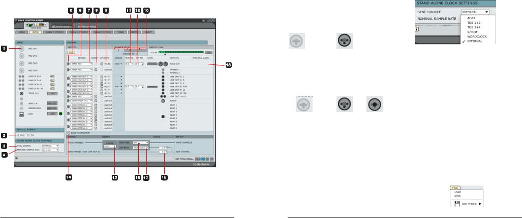
SETUP PAGE |
|
SETUP PAGE |
|
|
|
Input section
Overview of the input channels. Idle inputs are grayed out. If a device is connected to an input the icon will display this.
Example:
Nothing connected |
XLR device connected |
1Mic Ch1-4
Channels 1-4 connections on the front panel are autosensing. They automatically detect whether you have connected an XLR (microphone) or 1/4” jack (instrument), and display this graphically.
These are the options
Nothing connected |
Mic/XLR |
Inst./jack |
Optical Format
2Optical Input Format
Select between ADAT or TOS.
Stand-Alone Clock Settings
To apply the "stand-alone clock settings":
-power off the unit
-disconnect firewire cable form unit
-switch on the unit again
3Sync Source
See the options in the illustration above.
Studio Konnekt 48 will attempt to lock to the selected sync source. A steady orange LED above the meter for the relevant format indicates “lock”. A flashing LED indicates “no lock”.
4Nominal Sample Rate
Depending on the selected sample rate there are few restrictions with regards to the plug-ins.
Options are: |
|
44.1 kHz |
Both Fabrik R Studio and two Fabrik C |
& 48 kHz |
Studio are available |
88.2 kHz |
Fabrik R Studio and Fabrik C Studio |
& 96 kHz |
are available |
176,4 kHz |
Fabrik R Studio and Fabrik C Studio |
& 192 kHz |
are not available |
5File
The output section offers numerous choices of configuration and this section therefore has its own preset menu. Presets contain all the parameters in the output section. Load and Save files via this menu.
16 |
17 |
SETUP PAGE
Routing Channels to Outputs
Introduction - basics
The main purpose of the output section is routing of the physical, DAW and FireWire input channels to the physical outputs. Starting from left going to right we have the:
- the Source select that allows you to select the input you intend to route
-the option of routing source signal to any of the three speaker sets A, B, C and furthermore setting individual trim and delay for each source
-giving the outputs personal labels
6Link button
This button allows you to link/unlink channel pairs.
Example: Typically, you would prefer having main outputs linked, but you may unlink main L and main R if individual delay or trim is needed.
Linked
Unlinked
7Source select
Via the source select drop down menu you select the signal you are about to route. The options are:
Physical:
These are the physical inputs on Studio Konnekt 48.
.....let us take a look at each element of the Output section in detail.
SETUP PAGE
DAW
In this section you route the outputs of your DAW.
DSP
The DSP outputs are: Main, AUX1, AUX 2 outputs and Fabrik R sends. The AUX outputs are typically used for headphones.
Speaker Sets
Three speaker setups can be setup and switching between the sets is easy. The speaker setups A, B and C can be individually labeled according to your specific application.
8Speaker or Line level ?
In the speaker section you select whether the signal is routed to a speaker or directly to a line output at max level. If this box is checked the level can be controlled by the master level of the remote control. If not, line is sent to outputs regardless of the master level setting.
IMPORTANT !
If a source signal is NOT assigned to a speaker set, you can check “DIRECT” and thus route the signal directly to the mains out at FULL VOLUME.
If you e.g. have active monitors connected to the outputs and these set at full volume, then sending a signal, also at full volume, may damage the speakers.
A pop-up dialog box will ask you to reconsider before sending the un-attennuated signal to outputs.
9Assigned to
Indicates which speaker set or sets the source is assigned to.
18 |
19 |
SETUP PAGE
10Speaker sets
The speaker sets can be labeled individually. Simply click in the text field and enter a name of your choice.
Assigning an output to a speaker set
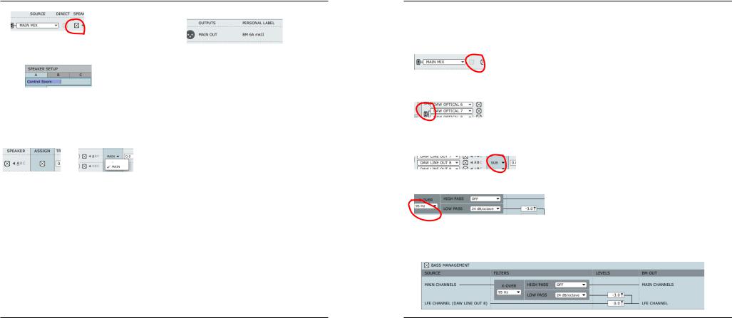
With no bass management an output is assigned directly to a speaker set by checking the ASSIGN check box for the output.
However, when bass management is used you must set main speakers to “main” and sub to “sub”.
Example: |
Example: |
Without Bass Management |
With Bass Management |
11Trim
Range: -20 dB to 0 dB
Individual trim levels for each channel.
12DLY
Range: 0 to 30 ms
Perfect listening conditions and placement of speakers according to an ITU 775 circle are not always possible. This delay parameter allows for individual alignment of speakers.
13Output label
The physical outputs have fixed names according to the labels on the rear panel. However, you can also add an additional personal label to these channel
outputs.
Bass management
The bass management system is designed to subtract the bass contents of all main channels and reproduce this by the use of a subwoofer and is easily set up with the Studio Konnekt 48.
Let us take at look at the components and how to set up bass management using the Studio Konnekt 48.
The Subwoofer
A subwoofer is a monitor that reproduces low frequencies. The purpose is to take over from the main monitor(s) as frequencies approach the lower end of the monitors frequency range. Depending on the performance and size of the main monitors the used threshold frequency between main monitors an sub, may vary from 80 to 120 Hz. From psycho-acoustics we know that there is no directional information in audio signals below approximately 120 Hz. Hence the advantage of placing the subwoofer in a position where the best distribution is achieved.
The LFE Channel
LFE is short for Low Frequency Enhancement or Low Frequency Effects, the first being the original name but the second being the most correct with regards to its application.
It is also referred to as the “.1”-channel, which indicates that the frequency range of this channel is only a fraction of the other channels in a multi-channel setup. The actual frequency range is 20 Hz to 120 Hz.
SETUP PAGE
14 Bass Management
For bass management to be active a few conditions must be setup:
-main channels must be assigned:
-for bass management of the main channels to be active, mark the bass management-box
-a subwoofer is connected to “line out 8” and thus any LFE channel should be routed to this output by setting Assign to “Sub”.
15X-OVER
Sets the X-over frequency for the main channels to determine the frequency where the main channel signal is split. Frequencies below this point is routed to the sub channel (line out 8).
16 + 17 High Pass & Low Pass
The high/low pass filters filtrate the signal before distribution to main and sub-channels. The high-pass filter is typically used when relatively small main monitors are used. The performance of such small main monitors will improve significantly, when they don’t have to reproduce very low frequency signals.
High-Pass
The high-pass filter filters the low-end frequencies from the main channels above the x-over frequency and according to the high-pass options.
-“off” - no high-pass filter
-“12 dB/octave” for a 12 dB slope above the X- over point
-“24 dB/octave” for a 12 dB slope above the X- over point
Low-Pass
The low-pass filter filtrates the high-end frequencies from the signal below the x-over frequency according to the low-pass options.
-“12 dB/octave” for a 12 dB slope below the X- over point
-“24 dB/octave” for a 24 dB slope below the X- over point
18Levels
Individual level adjustment for the LFE channel and the extracted signal below the X-over frequency.
20 |
21 |
 Loading...