


Impact Twin
User’s Manual
English Version
IMPORTANT SAFETY INSTRUCTIONS
The lightning flash with an arrowhead symbol within an equilateral triangle is intended to alert the user to the presence of uninsulated “dangerous voltage” within the
product’s enclosure that may be of sufficient magnitude to constitute a risk of electric shock to persons.
The exclamation point within an equilateral triangle is intended to alert the user to the presence of important
operating and maintenance (servicing) instructions in the literature accompanying the product.
1Read these instructions.
2Keep these instructions.
3Heed all warnings.
4Follow all instructions.
5Do not use this apparatus near water.
6Clean only with dry cloth.
7Do not block any ventilation openings. Install in accordance with the manufacturer’s instructions.
8Do not install near any heat sources such as radiators, heat registers, stoves, or other apparatus (including amplifiers) that produce heat.
9Do not defeat the safety purpose of the polarized or grounding-type plug. A polarized plug has two blades with one wider than the other. A grounding type plug has two blades and a third grounding prong. The wide blade or the third prong are provided for your safety. If the provided plug does not fit into your outlet, consult an electrician for replacement of the obsolete outlet.
10Protect the power cord from being walked on or pinched particularly at plugs, convenience receptacles, and the point where they exit from the apparatus.
11Only use attachments/accessories specified by the manufacturer.
12Use only with the cart, stand, tripod, bracket, or table specified by the manufacturer, or sold with the apparatus. When a cart is used, use caution when moving the cart/apparatus combination to avoid injury from tip-over.
13Unplug this apparatus during lightning storms or when unused for long periods of time.
14Refer all servicing to qualified service personnel. Servicing is required when the apparatus has been damaged in
any way, such as cord or plug is damaged, liquid has been spilled or objects have fallen into the apparatus, the apparatus has been exposed to rain or moisture, does not operate normally, or has been dropped.
Warning!
•To reduce the risk of fire or electrical shock, do not expose this equipment to dripping or splashing and ensure that no objects filled with liquids, such as vases, are placed on the equipment.
•This apparatus must be earthed.
•Use a three wire grounding type line cord like the one supplied with the product.
•Be advised that different operating voltages require the use of different types of line cord and attachment plugs.
•Check the voltage in your area and use the correct type.
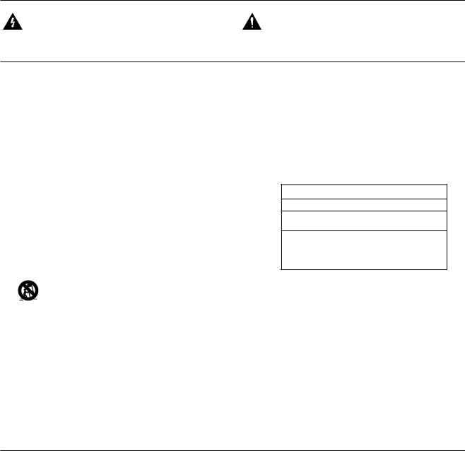
See table below:
Voltage |
Line plug according to standard |
110-125V UL817 and CSA C22.2 no 42.
220-230V CEE 7 page VII, SR section
107-2-D1/IEC 83 page C4.
240V BS 1363 of 1984.
Specification for 13A fused plugs and switched and unswitched socket outlets.
•This equipment should be installed near the socket outlet and disconnection of the device should be easily accessible.
•To completely disconnect from AC mains, disconnect the power supply cord from the AC receptacle.
•The mains plug of the power supply shall remain readily operable.
•Do not install in a confined space.
•Do not open the unit – risk of electric shock inside.
Caution:
You are cautioned that any change or modifications not expressly approved in this manual could void your authority to
operate this equipment.
Service
•There are no user-serviceable parts inside.
•All service must be performed by qualified personnel.
a

EMC / EMI
EMC/EMI
This equipment has been tested and found to comply with the limits for a Class B Digital device, pursuant to part 15 of the FCC rules.
These limits are designed to provide reasonable protection against harmful interference in residential installations. This equipment generates, uses and can radiate radio frequency energy and, if not installed and used in accordance with the instructions, may cause harmful interference to radio communications. However, there is no guarantee that interference will not occur in a particular installation. If this equipment does cause harmful interference to radio or television reception, which can be determined by turning the equipment off and on, the user is encouraged to try to correct the interference by one or more of the following measures:
•Reorient or relocate the receiving antenna.
•Increase the separation between the equipment and receiver.
•Connect the equipment into an outlet on a circuit different from that to which the receiver is connected.
•Consult the dealer or an experienced radio/TV technician for help.
For Customers in Canada:
This Class B digital apparatus complies with Canadian
ICES-003.
Cet appareil numérique de la classe B est conforme à la norme NMB-003 du Canada.
b
TABLE OF CONTENTS
INTRODUCTION |
|
Safety Instructions............................................. |
a |
EMC/EMI............................................................ |
b |
Table of Contents............................................... |
3 |
Introduction........................................................ |
5 |
Quick Setup Guide............................................. |
6 |
OVERVIEW |
|
Front Panel Overview........................................ |
8 |
Rear Panel Overview....................................... |
11 |
Mixer Page....................................................... |
12 |
Channel Sections 1+2...................................... |
14 |
Line 3-4 Module............................................... |
16 |
S/PDIF Module................................................. |
16 |
ADAT TOS Module.......................................... |
17 |
Lock Indication................................................. |
17 |
Reverb Module................................................. |
17 |
Master Module................................................. |
18 |
Patch Bay Module............................................ |
19 |
SETUP EXAMPLES |
|
Studio............................................................... |
20 |
Mobile studio.................................................... |
22 |
Ableton Live DJ................................................ |
24 |
Stand-alone...................................................... |
26 |
External Effect.................................................. |
27 |
To external mixer with ADAT in....................... |
28 |
Impact Twin as a Converter............................. |
29 |
Total Recall - File Menu................................... |
29 |
System Settings............................................... |
30 |
Buffers and Latency......................................... |
31 |
Audio Dropouts................................................ |
31 |
Operation Modes............................................. |
32 |
System Clock................................................... |
33 |
Versions........................................................... |
35 |
Reset to defaults.............................................. |
36 |
WDM Page....................................................... |
37 |
The Impact Tuner............................................. |
38 |
APPENDIX |
|
Bus Power Notes............................................. |
40 |
ASIO Channel Names...................................... |
41 |
Signal Flow...................................................... |
42 |
Miscellaneous.................................................. |
43 |
Shortcut Keys................................................... |
43 |
DICE Technology Background......................... |
43 |
Technical Specifications.................................. |
44 |
TC Electronic, Sindalsvej 34, DK-8240 Risskov – info@tcelectronic.com |
English Version |
Manual Revision 1.0 |
3 |
|
|
|

IMPACT TWIN INTRODUCTION
Impact Twin is a state-of-the-art audio interface featuring ground-breaking technology to ensure that the music you record sounds as good on the inside of your computer as it does on the outside. With the built-in preamp, converters and recording tools, Impact Twin offers a pristine path for your music to follow.
Two Microphone Preamps Featuring IMPACT III™ Technology
With these two pristine microphone preamps, you’ll never have to worry about recording quality again.
Channel Tools
Quickly and easily optimize the tone of your recordings with Impact Twin’s built-in channel tools.
FireWire 800 compatible (adapter included)
The included FireWire 800 adapter means you can connect the Impact Twin to just about any FireWire-equipped computer.
Direct Monitor Reverb
A simple way to add reverb at the monitor stage so the singer can enjoy quality reverb through his headphones.
Quick Compressor Access and Feedback
Access the crucial compressor setting directly from
Impact Twin’s front panel – and the light ring instantly shows the applied gain reduction.
14/14 I/O (4 analog, 10 digital I/O)
14 inputs and 14 outputs give the flexibility to record and monitor just about any device you can think of.
iCheck
The iCheck (Integrity Check) feature provides a shortcut for revealing artifacts of data reduction – essential when encoding files to lossy formats such as MP3 or AAC.
Hi-Z Guitar Optimized Inputs
Ensure the tone of your guitars is beautifully preserved with two front-panel mounted Hi-Z guitar-optimized inputs.
JetPLL Jitter Reduction
Everybody talks about analog sound quality, but what about digital? With built-in JetPLL jitter reduction technology, Impact Twin ensures superb audio quality all the way though the device.
Included Plug-ins
(M40 Reverb, ResFilter, Assimilator)
Impact Twin comes bundled with pristine TC effects processing. The M40 reverb is based on an algorithm from our acclaimed Reverb 4000 processor. The multi-purpose ResFilter provides ultra-fat filter sound. The Assimilator EQ curve assimilation tool lets you quickly grab an EQ curve from any sound and apply it to your own.
Sturdy design
While Impact Twin most probably will sit in your studio most of the time, the sturdy and cool design lets you take it anywhere, any time.
24 bit/192 kHz Operation
Capture the most detailed and transparent recordings you’ve ever heard – right up to ultra-detailed 192 kHz.
Guitar Tuner
Maintain perfect pitch with the built-in guitar tuner, which is always at hand.
5

QUICK SETUP GUIDE
Up and running in ten minutes
This quick guide will help you set up the IMPACT TWIN in a typical application. For further details and other usage scenarios, please refer to the following section of this manual.
Unpacking
•Open the box from the top and remove cabling.
•Remove Impact Twin from the plastic bag.
•Inspect your Impact Twin for signs of transit damage.
•In the unlikely event of transit damage having occurred, inform the carrier and the supplier.
•Keep all the packaging if damage has occurred, as this will show evidence of excessive handling force.
•It is also a good idea to keep the packaging if possible for future transportation.
Check Package Contents
The package should contain the following items:
•Impact Twin audio interface
•Power supply
•FireWire cable
•CD with software etc.
•Safety Instructions
•FireWire 800 adapter
•Quick start guide
Computer Requirements
Mac OS
•PowerPC (1 GHz or faster) or Intel CPU
•512 MB RAM
•FireWire (IEEE 1394) port*
•OS X 10.4.9 or later
Windows
•Pentium 4 (1.6 GHz or faster)
•512 MB RAM
•FireWire (IEEE 1394) port*
•Windows XP or Vista
* We recommend running each Impact Twin on a dedicated FireWire bus and not chaining them with other FireWire devices.
If your computer has one or more FireWire connector on its chassis, they will typically run on the same FireWire bus. You may connect the Impact Twin to one of these connectors. If you
intend to use additional FireWire devices (e.g. external hard drives) simultaneously, we recommend running these other devices on a separate bus.
This separate bus would typically be on an installed FireWire PCI or PCI Express card. Note that such a FireWire PCI card typically has three ports, but these also operate on a single bus.
Software Installation
•We recommend installing the software before connecting the Impact Twin.
•Refer to the TC Electronic Audio Interface Installation Guide supplied in the package and on the CD.
•If you are familiar with software installation procedures in general, you may simply insert the accompanying CD-ROM in your computer’s optical drive (CD or DVD) and follow the instructions.
•We always recommend using the latest software.
Updates are available for download at www. tcelectronic.com.
TC Near Control Panel
When the Impact Twin drivers are installed correctly, you can open the TC Near Control Panel.
On Windows Computers:
Open Start / Programs / TC Electronic / TC Near.
The TC Near Control Panel can also be accessed via the Windows Control panel.
On Mac Computers:
/Applications/TC Near
You may also start the TC Near Control Panel application from System Preferences.
PAGE HEAD
6

FRONT PANEL OVERVIEW
1FireWire/Power LED Indicator
When Impact Twin is hooked up via FireWire, the blue LED can indicate the following states:
Steadily lit: |
Sufficient power |
Flashing: |
Uploading firmware, hardware error or |
|
FireWire communication error. |
Off: |
The Impact Twin cannot establish |
|
a connection to the driver, maybe |
|
because the driver is not installed. |
Device Identification:
The blue LED will flash a couple of times when the “Impact Twin” tab in the control panel is selected. This comes handy if you have more than one TC audio interface connected to your computer. In this case, you can use the device tab to identify the audio interface.
2Mic/Inst CH1/CH2 on Combo XLR/Jack
Combo XLR/jack inputs. Both XLR and 1/4 inch jacks can be used with this connector.
The XLR Connection (Balanced)
Connect a microphone, and your signal is processed via the IMPACT™ mic pre-amps.
–When using condenser microphones, activate phantom power (see section 6 on the following page).
–The Input LEDs (4) indicate the level of the input signal. If the red O/L LED (overload) is lit, your signal is too “hot”, and you should press “PAD/INST” to attenuate the signal by 20 dB.
The 1/4 Jack Connection
–Press PAD/INST to activate this circuit.
The 1/4 “jack part” of the combo connector is a high-quality Hi-Z circuit that has been designed especially for connecting a passive guitar pick-up system (e.g. Strat-type) directly. The jack inputs on the front panel are unbalanced. If you wish to use balanced equipment using TRS jacks, you should connect them via the line inputs on the rear panel.
Important!
If you use the 1/4 jack part of the Combo jack/
 XLR connection, the PAD/INST selector must be set to “In” position.
FRONT PANEL OVERVIEW
3PAD/INST Selectors
The PAD/INSTRUMENT selector can attenuate the input sensitivity by 20 dB. If you cannot attenuate the signal sufficiently using the GAIN TRIM knob, you should use the -20 dB position. This is normally required when connecting line-level instruments.
4Input LEDs
Three Input level indicators: -30 dB, -10 dB and “O/L”.
The input LEDs indicate the level of the input signal. If the O/L LED (“Overload”) is lit, your signal might be too hot, and you should lower the input by using the GAIN TRIM knob or the 20 dB PAD switch. O/L indication should be used as a guide only. For more
precise level indication, please use the level meters in the control panel software.
5Gain/Trim
Use this control to set the appropriate input level (see previous paragraph).
6Phantom Power +48V
When this switch is pressed, the XLR part of the Combo XLR/Jack connections features +48V phantom power. Phantom power is used to power line-drivers and condenser microphones.
There are three main types of microphones:
Condenser microphone: Phantom power is required (except for some models that use proprietary power supplies or built-in batteries). Please check the microphone manufacturer’s specifications for details.
Electrodynamic microphone: Here, phantom power is not required (but does no harm to the microphone).
Ribbon microphones: Phantom power could damage these microphones! Please refer to the microphone’s documentation or the manufacturer’s support information.
Only condenser type microphones require phantom power. You can, however, combine e.g. a
condenser microphone on channel 1 with a standard electrodynamic microphone (e.g. a Shure SM57) on channel 2 without problems. You can also activate phantom power and use a condenser microphone on one of the inputs and connect a guitar using a 1/4 jack to the other input, as the phantom power only goes to the XLR pins.
7Line In – Ch 1/2 Input Selector
Use this switch to select either front panel or rear panel inputs for channels 1/2.
Rear panel inputs are line inputs.
When you select Line In 1+2, you’ll see the TC Near mixer page conveniently collapse the Channels 1+2 section.
Connect any secondary device that you don’t use in music production to Line inputs 1/2 on the rear panel. Use the “Line In” switch to alternate between front and rear panel inputs.
8/9/10 ADJUST Dialer
The ADJUST dialer can be used to adjust the function selected with the FUNCTION selector (10):
–Compression amount on channel 1
–Compression amount on channel 2
–Reverb amount / Decay time
–DAW mix input / 100 % DAW
The selected function is indicated by the four LEDs (9).
ADJUST Dialer – Push Function
A few extra features are built in the ADJUST knob and its push function.
Example #1 – Compression Mode:
–Press the function selector (10) and select compression mode.
8 |
9 |

FRONT PANEL OVERVIEW
–Now turn the ADJUST dialer to set the compression amount.
–Press the ADJUST knob once to bypass the compressor.
–Turning the ADJUST dialer again will automatically reactivate the compressor, and the compression amount can be adjusted again starting from 0 %.*
* This feature prevents you from accidently setting an extreme compression amount while the compressor is bypassed.
Example #2 – Compression Mode A/B Listening:
–Press the function selector (10) and select compression mode.
–Now turn the ADJUST dialer to set the compression amount.
–Press the ADJUST knob several times to compare compressed and uncompressed signal (A/B listening).
–If you turn the ADJUST knob while the compressor is
“on” you will now adjust from the current compression amount.
Example #3 – using ADJUST to control Decay time and and Reverb amount
–Press the function selector (10) and select “REV”.
–Now press the ADJUST encoder to toggle between letting the encoder control Reverb amount or decay time.
11Output Level Knob
Sets the output level of analog outputs 1-2 and of the headphone outputs.
12Listening Mode selector: Stereo / Mono / Side
MONO: Listen to your signal in mono. The left and right channel are summed and sent to both outputs.
SIDE: Listen only to the SIDE component of your signal (in this mode, the M/S decoding algorithm is active).
Monitoring the side component is especially interesting when comparing a data-reduced format (such as MP3 or AAC) to a linear signal or to a data-reduced signal at a different bit rate, since artifacts from MP3 or AAC encoding are highly exposed in the side component.
13Phones – Muting
When you connect a set of headphones to this jack, main outputs will be muted.*
14Phones – Non-muting
When you connect a set of headphones to this jack, the signal is still passed to the main outputs.*
 * Both Phones outputs can be used simultaneously.
This feature allows you to listen not only in stereo mode (standard), but also monitor the mono and side components separately.
STEREO: You are listening to your signal in stereo (this is the default setting).
REAR PANEL OVERVIEW
1Power Switch
On/off switch for the unit.
2Power In Jack
Impact Twin can be bus-powered from the computer’s FireWire port if your computer supplies bus power. Check your computer’s specifications. If more than one bus-powered audio interface is used or if your computer delivers insufficient power on the FireWire port, use the supplied 12 VDC power supply.
3FireWire Connectors
IEEE 1394 connectors for connecting to a computer and/or linking multiple Impact Twin units. Impact Twin can be bus-powered* from the computer’s FireWire port. Check your computer’s specifications.
Before plugging the FireWire connectors, make sure that plugs are positioned correctly.
*Please read the manual section on bus-power.
4MIDI In/Out
Standard MIDI In/Out jacks.
5S/PDIF – Digital In/Out – Coaxial
24 bit digital in/out on S/PDIF. Instead of operating these digital connectors as input and output, you can also use them to insert e.g. an external digital effects unit – and use this as a send effect in the direct monitoring audio path.
6Line Outputs (balanced)
1/4 inch TRS jack outputs for:
–Main Left (CH1) and Main Right (CH2)
–Left (CH3) and Right (CH 4)
When connecting the Main outputs to a device (e.g. active speakers) with unbalanced inputs, “ground” and “cold” must be connected. On XLR type plugs, these are the pins 1 and 3. On Jack type plugs, these are the “sleeve” and “ring” parts.
7 |
Line Inputs (balanced) |
|
|
|
|
– |
Ch 1 |
(Left) |
– |
Ch 3 |
(Left) |
– |
Ch 2 |
(Right) |
– |
Ch 4 |
(Right) |
8DI/DO – ADAT/TOS In/Out
Optical S/PDIF or ADAT for up to 8 channels of digital I/O, depending on format and sample rate.
10 |
11 |

TC NEAR CONTROL PANEL – MIXER PAGE
Patchbay
Module
Channel Strip
Presets
Info (mouse-over) tips |
Channel Sections 1+2 |
Line 3+4 |
S/PDIF |
ADAT/TOS |
Reverb |
Master |
File |
- on/off |
|
Module |
Module |
Module |
Module |
Module |
Menu |
12 |
13 |
 Loading...