


G-major
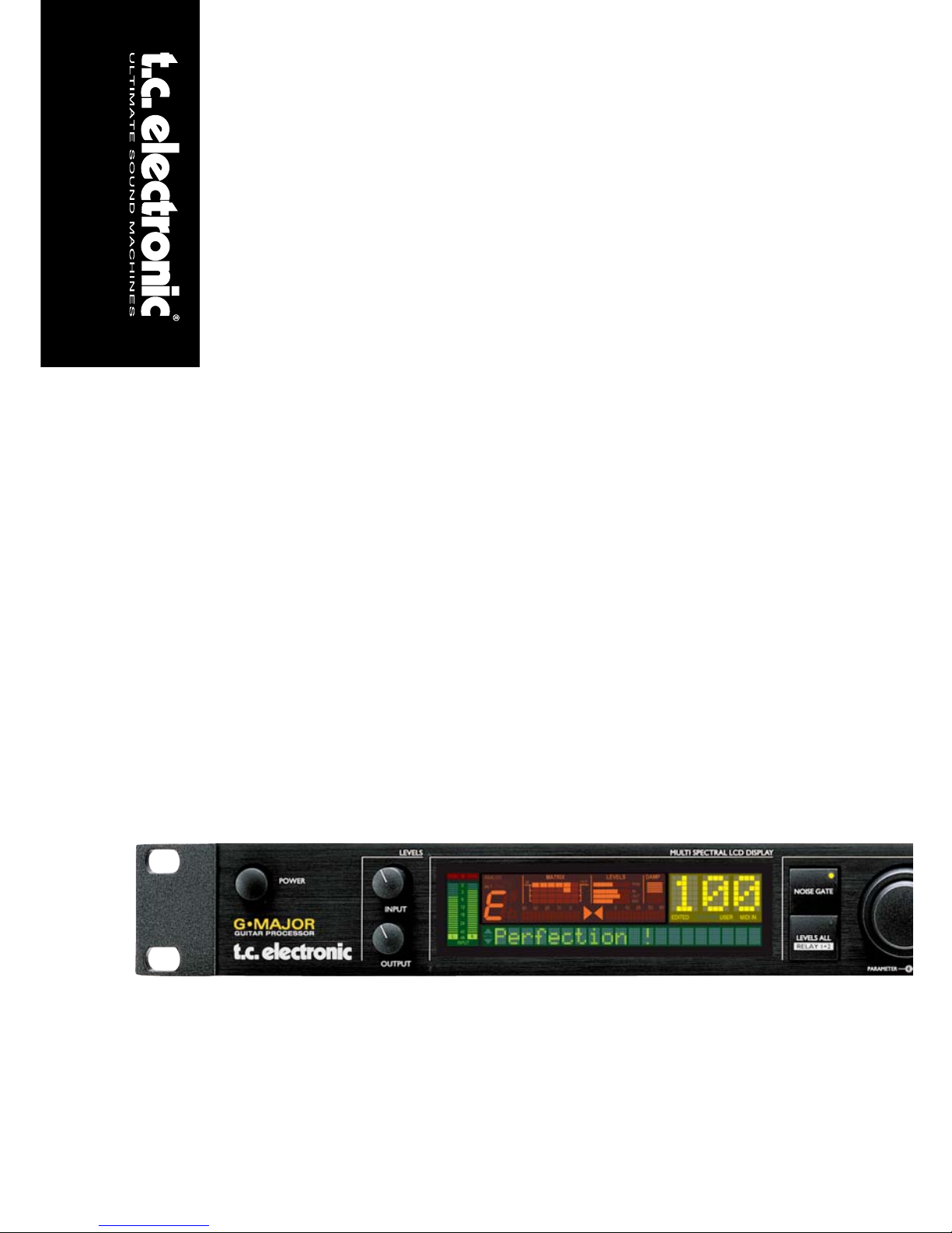
G•Major
GUITAR EFFECTS PROCESSOR
UUSSEERR’’SS MMAANNUUAALL
Downloaded from www.Manualslib.com manuals search engine

Downloaded from www.Manualslib.com manuals search engine
a
IMPORTANT SAFETY INSTRUCTIONS
1 Read these instructions.
2 Keep these instructions.
3 Heed all warnings.
4 Follow all instructions.
5 Do not use this apparatus near water.
6 Clean only with dry cloth.
7 Do not block any ventilation openings. Install
in accordance with the manufacturer's
instructions.
8 Do not install near any heat sources such
as radiators, heat registers, stoves, or other
apparatus (including amplifiers) that produce
heat.
9 Do not defeat the safety purpose of the
polarized or grounding-type plug. A
polarized plug has two blades with one
wider than the other. A grounding type plug
has two blades and a third grounding prong.
The wide blade or the third prong are provided
for your safety. If the provided plug does not fit
into your outlet, consult an electrician for
replacement of the obsolete outlet.
10 Protect the power cord from being walked
on or pinched particularly at plugs,
convenience receptacles, and the point
where they exit from the apparatus.
11 Only use attachments/accessories specified
by the manufacturer.
12 Unplug this apparatus during lightning storms
or when unused for long periods of time.
Use only with the cart, stand, tripod,
bracket, or table specified by the
manufacturer, or sold with the apparatus.
When a cart is used, use caution when
moving the cart/apparatus combination to
avoid injury from tip-over.
13 Refer all servicing to qualified service
personnel. Servicing is required when the
apparatus has been damaged in any way,
such as power-supply cord or plug is
damaged, liquid has been spilled or objects
have fallen into the apparatus, the
apparatus has been exposed to rain or
moisture, does not operate normally, or has
been dropped.
• This equipment should be installed near the
socket outlet and disconnection of the device
should be easily accessible.
• To completely disconnect from AC mains,
disconnect the power supply cord from the AC
receptable.
• The mains plug of the power supply shall
remain readily operable.
• Do not install in a confined space.
• Do not open the unit - risk of electric shock
inside.
Caution:
You are cautioned that any change or
modifications not expressly approved in this
manual could void your authority to operate this
equipment.
Service
• There are no user-serviceable parts inside.
• All service must be performed by qualified
personnel.
Warning!
• To reduce the risk of fire or electrical shock,
do not expose this equipment to dripping or
splashing and ensure that no objects filled
with liquids, such as vases, are placed on the
equipment.
• This apparatus must be earthed.
• Use a three wire grounding type line cord
like the one supplied with the product.
• Be advised that different operating voltages
require the use of different types of line
cord and attachment plugs.
• Check the voltage in your area and use the
correct type. See table below:
Voltage Line plug according to standard
110-125V UL817 and CSA C22.2 no 42.
220-230V CEE 7 page VII, SR section
107-2-D1/IEC 83 page C4.
240V BS 1363 of 1984.
Specification for 13A fused
plugs and switched and
unswitched socket outlets.
The lightning flash with an arrowhead
symbol within an equilateral triangle, is
intended to alert the user to the
presence of uninsulated "dangerous voltage" within the product's enclosure that may be of
sufficient magnitude to constitute a risk of
electric shock to persons.
The exclamation point within an
equilateral triangle is intended to alert
the user to the presence of important
operating and maintenance (servicing)
instructions in the literature accompanying the
product.
Downloaded from www.Manualslib.com manuals search engine

IMPORTANT SAFETY INSTRUCTIONS
Certificate Of Conformity
TC Electronic A/S, Sindalsvej 34, 8240
Risskov, Denmark, hereby declares on own
responsibility that following products:
G•Major - Guitar Effects Processor
- that is covered by this certificate and
marked with CE-label conforms with
following standards:
EN 60065 Safety requirements for mains
(IEC 60065) operated electronic and
related apparatus for household
and similar general use
EN 55103-1 Product family standard for
audio,video, audio-visual and
entertainment lighting control
apparatus for professional
use. Part 1: Emission.
EN 55103-2 Product family standard for
audio, video, audio-visual and
entertainment lighting control
apparatus for professional
use. Part 2: Immunity.
With reference to regulations in following
directives:
73/23/EEC, 89/336/EEC
Issued in Risskov, January 2001
Anders Fauerskov
Chief Executive Officer
b
EMC / EMI.
This equipment has been tested and found to
comply with the limits for a Class B Digital
device, pursuant to part 15 of the FCC rules.
These limits are designed to provide
reasonable protection against harmful
interference in residential installations. This
equipment generates, uses and can radiate
radio frequency energy and, if not installed and
used in accordance with the instructions, may
cause harmful interference to radio
communications. However, there is no
guarantee that interference will not occur in a
particular installation. If this equipment does
cause harmful interference to radio or television
reception, which can be determined by turning
the equipment off and on. The user is
encouraged to try to correct the interference by
one or more of the following measures:
• Reorient or relocate the receiving antenna.
• Increase the separation between the
equipment and receiver.
• Connect the equipment into an outlet on a
circuit different from that to which the
receiver is connected.
• Consult the dealer or an experienced
radio/TV technician for help.
For the customers in Canada:
This Class B digital apparatus complies with
Canadian ICES-003.
Cet appareil numérique de la classe B est
conforme à la norme NMB-003 du Canada.
Downloaded from www.Manualslib.com manuals search engine

3
TABLE OF CONTENTS
INTRODUCTION
Important Safety Instructions . . . . . .a-b
Table of Contents . . . . . . . . . . . . . . . .3
Introduction . . . . . . . . . . . . . . . . . . . . .5
Front Panel Overview . . . . . . . . . . . . .6
Rear Panel Overview . . . . . . . . . . . . .8
Signal Flow Diagram . . . . . . . . . . . . . .9
Basic Setups . . . . . . . . . . . . . . . . . . .10
OPERATION
The Display . . . . . . . . . . . . . . . . . . .12
Preset Handling
Recall . . . . . . . . . . . . . . . . . . . . . . . .13
Edit . . . . . . . . . . . . . . . . . . . . . . . . . .13
Store . . . . . . . . . . . . . . . . . . . . . . . . .13
Preset Backup Via MIDI . . . . . . . . . .14
Setting up
I/O Setup . . . . . . . . . . . . . . . . . . . . .14
Utility & MIDI . . . . . . . . . . . . . . . . . . .15
The Tuner . . . . . . . . . . . . . . . . . . . . .17
MIDI Mapping . . . . . . . . . . . . . . . . . .18
Levels All menu . . . . . . . . . . . . . . . .19
Channel Switching of
External Preamp with Relay 1+2 . . . .19
Kill Dry Function . . . . . . . . . . . . . . . .19
Routings . . . . . . . . . . . . . . . . . . . . . .21
Tap Tempo Menu . . . . . . . . . . . . . . .21
Controlling the G•Major
Introduction . . . . . . . . . . . . . . . . . . . .22
The Mod (modifier) Menu . . . . . . . . .22
Modifiers . . . . . . . . . . . . . . . . . . . . . .23
Assigning Modifiers . . . . . . . . . . . . . .24
How To....
Examples on various operations . . . .25
EFFECT BLOCKS
Introduction . . . . . . . . . . . . . . . . . . . .27
Effects Menu - Basic operation . . . . .27
Noise Gate . . . . . . . . . . . . . . . . . . . .27
EQ . . . . . . . . . . . . . . . . . . . . . . . . . .28
Compressor . . . . . . . . . . . . . . . . . . .29
Chorus . . . . . . . . . . . . . . . . . . . . . . .30
Flanger . . . . . . . . . . . . . . . . . . . . . . .32
Vibrato . . . . . . . . . . . . . . . . . . . . . . .33
Resonance Filter . . . . . . . . . . . . . . . .34
Phaser . . . . . . . . . . . . . . . . . . . . . . .35
Tremolo . . . . . . . . . . . . . . . . . . . . . .36
Panner . . . . . . . . . . . . . . . . . . . . . . .36
Delay . . . . . . . . . . . . . . . . . . . . . . . .38
Pitch Detune . . . . . . . . . . . . . . . . . . .39
Whammy . . . . . . . . . . . . . . . . . . . . .40
Pitch Shifter . . . . . . . . . . . . . . . . . . .41
Reverb . . . . . . . . . . . . . . . . . . . . . . .42
APPENDIX
MIDI Implementation . . . . . . . . . . . . .46
Technical Specifications . . . . . . . . . .47
Preset List . . . . . . . . . . . . . . . . . . . .48
Frequently Asked Questions . . . . . . .49
TC Electronic, Sindalsvej 34, DK-8240 Risskov – tcdk@tcelectronic.com Rev 7.1 – SW – V 1.26English Version
Prod. No: E60500902
Downloaded from www.Manualslib.com manuals search engine
INTRODUCTION
Congratulations on the purchase of your G•Major Effects processor.
If you have never used a multi-effects processor with your guitar rig, you might be wondering at this
point whether you have placed yourself in a position where you have days of work ahead of you,
until your G•Major behaves as you please and adds to your creativity. No need to panic!
With the presets already existing your basic needs are most likely covered and you will be set to go
within minutes.
But chances are that you probably will like to go beyond factory presets and find a more
personalized usage of the G•Major - and that won’t be a hassle either.
S
tomp Box Setup
If you are used to working with stomp boxes you might want to use the G•Major for a similar setup
and simply benefit from high quality of effects. With any MIDI pedal sending MIDI Control Change
values the G•Major can be setup and used just as a bunch of regular stomp boxes where you
simply turn effects on and off.
Preset Setup - for ultimate changes in sounds
Another approach would be creating unique presets for each sound accessible via a single press on
a MIDI foot-controller.
Or - you could combine the preset-approach with the on/off-stomp box setup mentioned above.
Channel Switching
Changing your sound from a crisp clean dry rhythm sound to an overdriven lead sound, will often
involve channel switching of your preamp or combo in addition to changing your effects preset. To
be able to switch amp-channels via MIDI the investment of a separate MIDI switching system is
often implied. Not with the G•Major. With the built in Relay Switching on the G•Major you are able to
switch between up to 4 channels on you Preamp/Combo.
Modifiers - Inst
ant parameter control
If utilizing the above still doesn’t give you the sought after flexibility you are looking for, instant
parameter control via the Modifier section of the G•Major is probably the answer. Many algorithm
parameters can be assigned to an external MIDI controller or Expression pedal. The possibilities
here are endless. With an Expression Pedal you can not only control any level of a specific effect,
you could also e.g. change the Panning Speed - or what about using the Expression pedal as a
customized Whammy pedal.
Downloaded from www.Manualslib.com manuals search engine
5
Quality
With the G•Major, TC Electronic introduces a Guitar Effects Processor in the “affordable” price
range. You should however not be deceived by the price as the G•Major delivers true top quality
processing with no unwanted coloring of your beloved guitar-tone. As one of the leading companies
in the business of signal processing the vast amount of knowledge and experience concentrated at
TC Electronic is all for your benefit. Though each product is unique it is worth noticing the success
and achievement gained on other products from TC Electronic. Prices won for astounding Reverb
quality, Compression techniques and numerous other classic TC effects such as Dynamic Delay
and Chorus guaranties also the quality of this product. Logical operation via the intuitive user
interface will let you setup a series of quality sounds accessible from any attached MIDI pedal in
just a few minutes.
The quality of the effects in the G•Major are guaranteed, but furthermore we are confident that once
you have spend a few hours twisting the few controls on the G•Major, assisted with this manual,
you will start to appreciate the numerous possibilities within the G•Major.
About this manual
The latest manual revision and translations can be downloaded via www.tcelectronic.com
If you have questions unanswered by this manual try looking at our TC Support Interactive site. This
site is also accessed via www.tcelectronic.com
INTRODUCTION
Downloaded from www.Manualslib.com manuals search engine
6
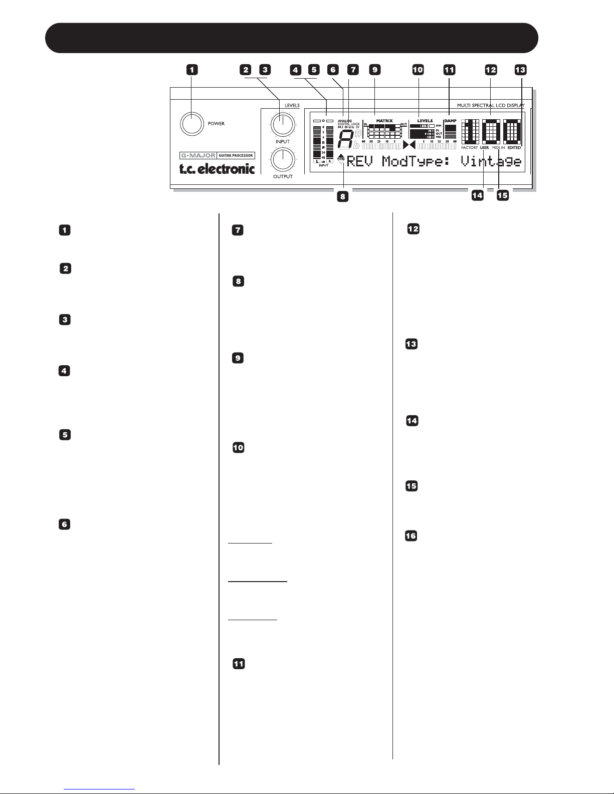
FRONT PANEL OVERVIEW
POWER KEY
On/Off switch for the unit.
INPUT LEVEL KNOB
Adjusts the Input level.
Range: 24dB
OUTPUT LEVEL KNOB
Adjusts the Output level.
Range: 24dB
INPUT METERS
Peak meter showing Input level.
The Meter range is: 0, -3, -6 ,
-12, -18, -24, -40dB.
INPUT OVERLOAD LEDS
The Overload LEDs indicates
one of two situations: The Input
level is too hot and therefore
overloading or there is an
internal DSP overflow.
INPUT TYPE -
ANALOG DIGITAL
Input selection is done in the I/O
section accessed by pressing
the I/O key.
Analog: Indicates analog Input
mode is selected.
Digital Lock: Indicates that
digital lock is achieved with a
device connected to the Digital
Input.
44.1/48kHz: Indicates whether
the achieved digital lock is at
44.1kHz or at 48kHz.
If a digital device is connected to
the digital Input on the G•Major
but no lock is achieved, the
Digital Lock indication will blink.
DI LED
Indicates that external digital
Clock Input is selected.
TUNER
The G•Major holds a Tuner. The
tuner is always active. When the
instrument is in tune the two
arrows will both be lit.
THE MATRIX
The G•Major holds 3 different
effect block routing options.
Serial, Semi Parallel and
Parallel. The matrix illustrates
the structure of the used routing.
LEVELS SECTION
These parameters refer only to
the block being edited.
PPM - Peak Program Meter:
Indicates the peak level of the
effect block currently being
edited.
IN Meter:
Indicates the block Effect Input
Level.
OUT Meter:
Indicates the Effect block Output
Level.
MIX Meter
Indicates the Effect Block
Mix level.
DAMP
If both the Noise Gate and the
Compressor is in use the DAMP
indicator will indicate the Noise
Gate attenuation when no Input
signal is present and the applied
compression where Input signal
is present.
PRESET NUMBER
When steady the currently
recalled preset number is
displayed. When
previewing presets the
number will blink until the
preset is recalled by
pressing the RECALL key.
EDITED
When this LED is lit the
currently recalled preset
has been edited but not
yet stored.
FACTORY/USER
Indicates whether you are
operating in the Factory or
in the User bank.
MIDI IN
Indicates incoming MIDI
information.
SELECT (Outer)
- ADJUST (Inner) wheels
The two wheels are used
to handle mix parameters
from each effect block.
Turn the outer SELECT
wheel to scroll between
mix parameters and use
the ADJUST wheel to set
value. After 2 seconds
untouched, the display
returns to its previous
state.
Downloaded from www.Manualslib.com manuals search engine
7
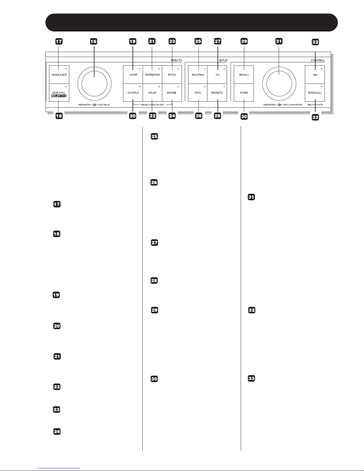
FRONT PANEL OVERVIEW
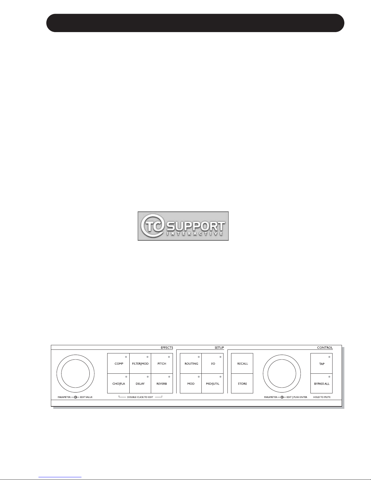
FRONT PANEL KEYS
GENERAL INFORMATION
A single click will activate/
deactivate the effect. Double
clicking on the key will enter
the Edit menu of the effect
algorithm.
Lit key LED indicates active
effect block.
NOISE GATE KEY
On/off key for the Noise Gate
block.
LEVELS ALL/ RELAY 1+2
Press to access global Level
parameters, Kill Dry function
and settings for the two Relay
switches that will allow you to
e.g. switch channels on you
combo/head or preamp.
COMP
On/Off key for the Compressor
block.
CHO/FLA
On/Off key for the Chorus/
Flanger block.
FILTER/MOD
On/Off key for the Filter and
Modulation block.
DELAY
On/Off key for the Delay block.
PITCH
On/Off for the Pitch block.
REVERB
On/Off key for the Reverb block.
ROUTING
Press to access the Routing
section. This is where you
select the routing of your effect
blocks.
MOD
Press to access the Modifier
section. This is where you
setup which parameters that
should be controlled externally,
e.g. via a connected
Expression Pedal.
I/O
The I/O menu is where you
control all Input and Output
related parameters.
MIDI/UTIL
Press to access all MIDI and
other general parameters.
RECALL
Press RECALL to initiate a
recall operation. Use the EDIT
wheel in the Control section
(inner wheel) to select preset.
Then press ENTER (EDIT
wheel) or RECALL to confirm
operation.
STORE
Press STORE once to initiate
a store operation. Select
location using the EDIT wheel
in the Control section (inner
wheel). Now press ENTER to
confirm operation.
The name of the preset can be
altered before pressing
ENTER for confirmation. To do
so use the PARAMETER
wheel in the Effects section to
select letter-space and the
VALUE wheel to select letter.
When the name is set press
ENTER twice to confirm entire
STORE operation.
PARAMETER WHEEL
(Outer)
EDIT WHEEL (Inner)
ENTER (Push for Enter
function)
These two wheels are used to
handle all setup and noneffects related parameters.
The PARAMETER wheel is
used to select parameters.
The EDIT wheel is used to
adjust values.
Push the EDIT wheel for Enter/
Confirm functions.
TAP
Tap to enter global tempo.
Effects related to tempo as
e.g. the Delay block can use
this tempo or a subdivision
thereof. The LED in the key
will blink according to the
current global tempo.
BYPASS ALL
Press to bypass all effects.
Press and hold for approx. 1
sec to mute Outputs for e.g.
silent tuning.
Downloaded from www.Manualslib.com manuals search engine
8
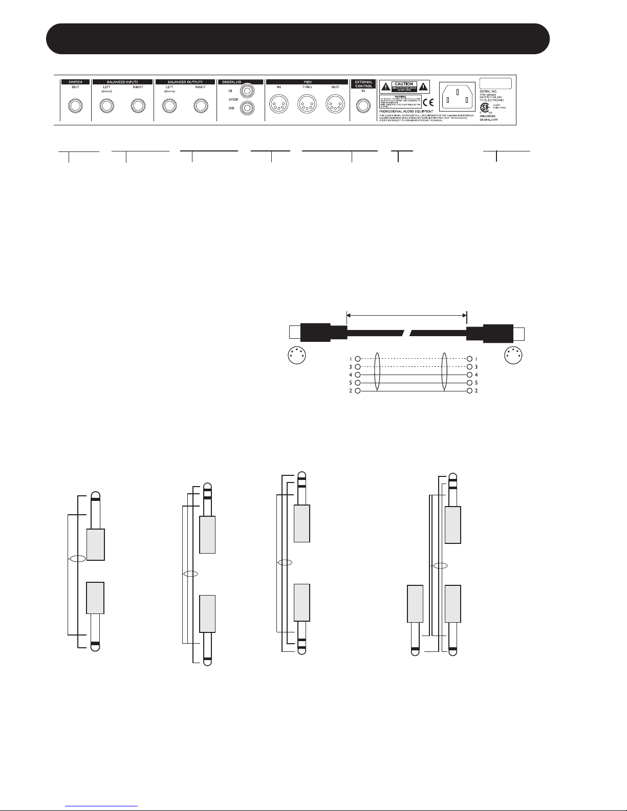
REAR PANEL
Balanced
Jack
Analog
Inputs
Balanced
Jack
Analog
Outputs
External
Control
MIDI
In, Out, Thru
Switch
Out
Relay
Jack
Digital
S/PDIF
Input/
Output
Power
Input
100 - 240V
Relay Jack Cable
- Y-Splitter Type
Jack Cable
Stereo to Mono
Jack Cable
Mono to Mono
TIP
RING
GND
GND
TIP
GND
TIP
MIDI Cable
DIN CONNECTOR
5POLE - MALE
45 degrees
DIN CONNECTOR
5POLE - MALE
45 degrees
max. 10m
SHIELDED CABLE (3 or 5 wires + screen)
Note!
The analog Input and Output connectors
on the G•Major are balanced 1/4” jacks.
Optimal connection to balanced equipment
is achieved using balanced cables.
However most guitar equipment is NOT
balanced and you will generally have no
problems using standard mono-to-mono
cables as illustrated below.
TIP
RING
GND
GND
TIP
GND
TIP
TIP
GND
TIP
RING
GND
GND
RING
TIP
Relay Jack Cable
- Stereo Jack Type
Downloaded from www.Manualslib.com manuals search engine
9
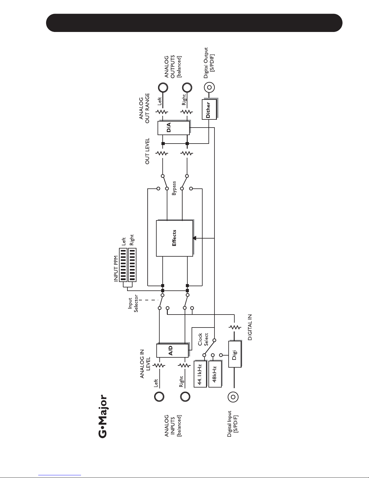
SIGNAL FLOW
Downloaded from www.Manualslib.com manuals search engine
10
BASIC SETUPS
Connecting and Setting up the G•Major
There are numerous ways of hooking up guitar rigs. On these pages we have listed some of the
most commonly used setups. We recommend using serial setups where the entire signal passes
through the G•Major. This will give you the maximum benefit from all effect algorithms. As stated
several times in this manual, you should NOT worry about coloring of your sound as TC Electronic
uses top quality converters that does NOT color your tone.
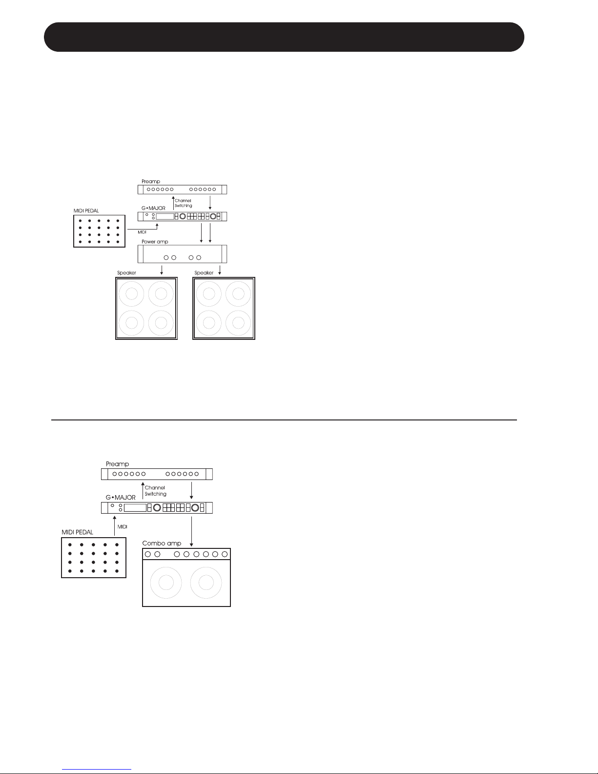
Serial Setup with Preamp and Power Amp
• Connect the Output of your preamp to
the Input of the G•Major.
• Connect the Output of the G•Major to
the Input of your power amp.
• To be able to switch preamp channels
with the G•Major connect the Relay
Jack connection on the G•Major to the
channel switching jacks on the preamp.
(This does not apply for MIDI preamps).
Serial Setup with Preamp and one or two
Combo Amps
• Connect the Output of your preamp to the
Input of the G•Major.
• Connect the Output of the G•Major to either
the Input or the Loop Return of the Combo or
Combos.
• To be able to switch preamp channels with
the G•Major, connect the Relay Jack
connection on the G•Major to the channel
switching jacks on the preamp. (this does not
apply for MIDI preamps).
Using the return on the Combo’s effect loop will
in most cases give you a setup similar to the
power-amp setup described above.
Using the regular Input on the Combo gives you
a “double-preamp” setup where you can use the
tone controls on the Combo to color your
sound. This introduces more noise than when
using the Effect Return connection, but has
become a popular setup with amplifiers like Vox
AC 30, Fender Bassman etc.
Downloaded from www.Manualslib.com manuals search engine
11
BASIC SETUPS
Connecting and Setting up the G•Major
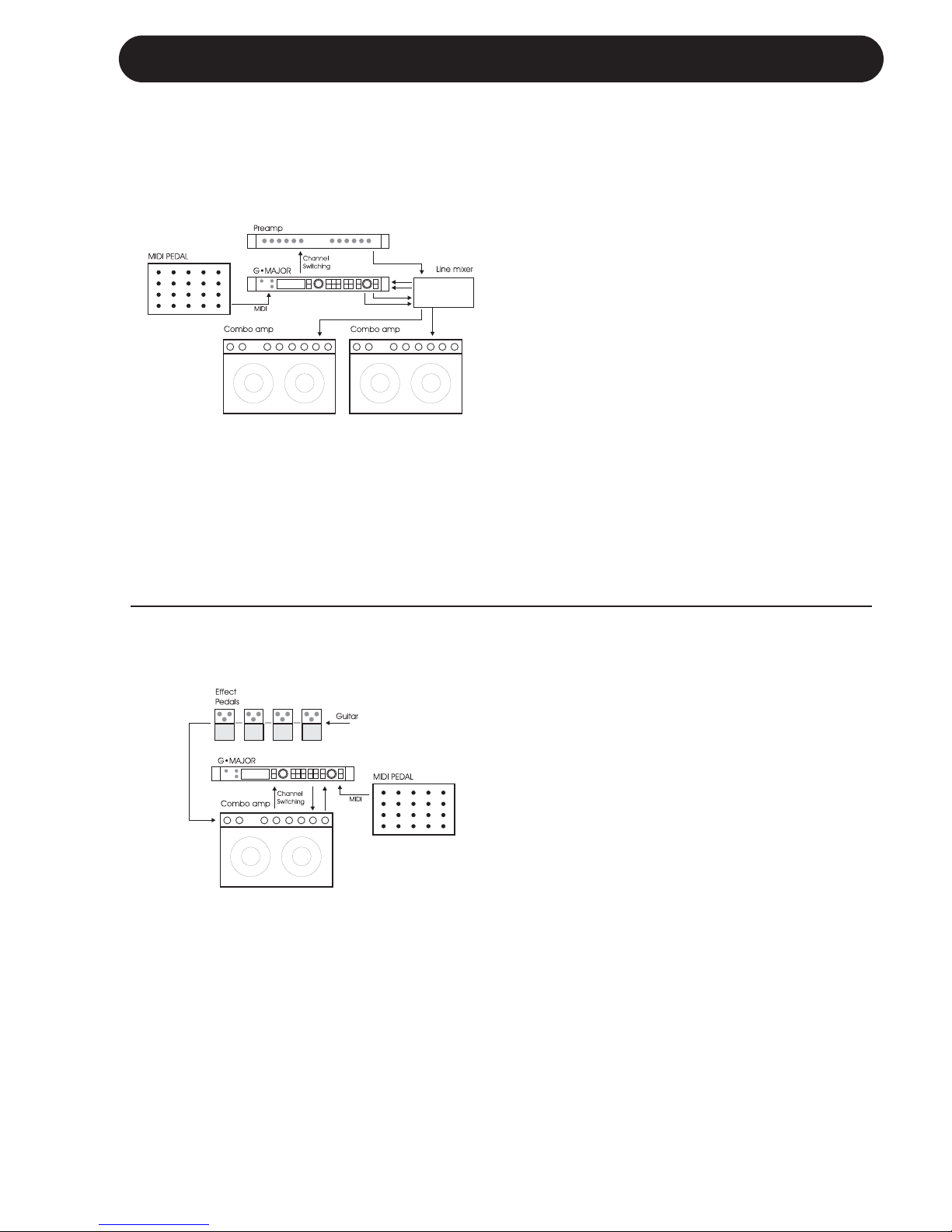
Parallel Setup using a Line Mixer
• Connect the Output of your preamp to the
Input of the Line Mixer.
• To be able to switch preamp channels with
the G•Major connect the Relay Jack
connection on the G•Major to the channel
switching jacks on the preamp.
(this does not apply for MIDI preamps).
• Connect the Line Mixer Loop Outputs to the
G•Major Inputs and the G•Major Outputs to
the Line Mixer Loop Inputs.
• Connect the Line Mixer main Outputs to
your amplification.
The Illustration shows Combos - these could
also be a power amp, and the Preamp could
easily be the Preamp-section of a Combo
amplifier.
Combined Setup with Regular Effect
Pedals, a G•Major and a MIDI pedal
• Connect the Combo’s Effect loop Out to the
G•Major Input.
• Connect the G•Major Output to the Effect
loop Input.
• Connect your guitar to your pedals and your
pedals to the Input of the Combo as usual.
• If you wish to switch presets on the G•Major
e.g. including Channel switching of the
Preamp/Combo you should also connect a
MIDI pedal to the G•Major and use the
Relay Switching function.
Downloaded from www.Manualslib.com manuals search engine
12
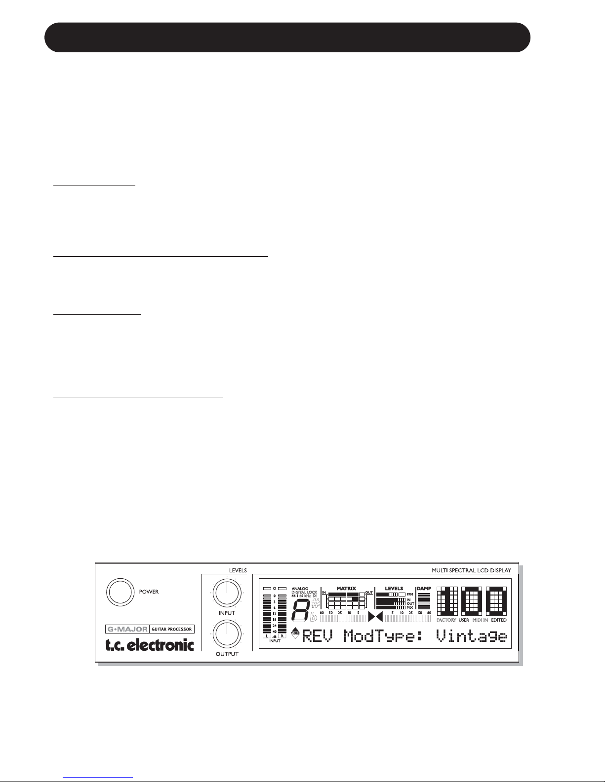
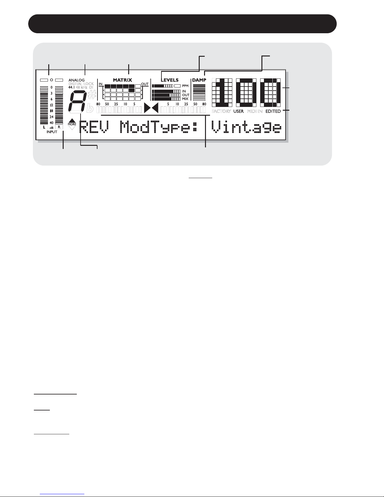
THE DISPLAY
Input Meter
Overload
LEDs
Input Type
Indicator
Matrix - indication of
currently used Routing
Block Levels In/Out and Mix
Damp
Compression/
Noise Gate
Preset
Number
Indicators of:
Received
MIDI
Factory/User
preset bank
Edit
indication
TunerDetected Input Pitch
Input Meters
Peak meter showing Input level.
The Meter range is: 0, -3, -6, -12, -18, -24, -40dB.
To set correct Input level:
Select the “loudest” sounds containing the most
dynamic content on the equipment you are
feeding the G•Major with, e.g. your preamp.
This will probably be a clean sound. Adjust the
Input level at the G•Major so the -3dB LED
flashes frequently and the -0dB LED flashes
only at absolutely highest levels.
Input Overload LEDs
The Overload LEDs indicates one of two
situations:
The Input level is too hot and therefore
overloading or there is an internal DSP
overflow. The Overload LED is lit when 1
sample is @ 0dBFS.
Reduce either the Output of the device feeding
the G•Major or Input gain on the G•Major using
the Input level knob.
Input Type and Clock
Input selection is done in the Utility section
accessed by pressing the I/O key.
Analog/Digit
al: Indicates selected Input mode.
Lock: Indicates that digital lock is achieved with
a device connected to the Digital Input.
44.1/48kHz:
Indicates the current Clock Rate.
DI LED: Indicates that external digital Clock
Input is selected.
If a digital device is connected to the digital
Input on the G•Major but no lock is achieved,
the Lock indication will blink. Check cables and
Clock Rate on the connected device and try
again.
Tuner
The G•Major holds a Tuner, which is always
active. The two arrows will both be lit when the
instrument is in tune.
If a TC Electronic G•Minor MIDI pedal (optional)
is used you can also have the Tuner displayed
in the Pedal.
The Matrix
The G•Major holds 3 different effect block
routing options.
This matrix indicates which of the three that is
used.
Levels Section
These parameters refer only to the block being
edited.
PPM - Peak Program Meter:
Indicates the level of the block currently being
edited.
IN Meter:
Indicates the present Input Level in the block
currently being edited.
OUT Meter:
Indicates the parameter position of the Output
Level in the block currently being edited.
Downloaded from www.Manualslib.com manuals search engine

13
THE DISPLAY PRESET HANDLING
MIX Meter:
Indicates the parameter position of the Mix level
in the block currently being edited.
DAMP
If both the Noise Gate and the Compressor is in
use the DAMP indicator will indicate the Noise
Gate attenuation when no Input signal is
present and the applied compression when
Input signal is present.
Preset Number
When steady the currently recalled preset
number is displayed. When previewing presets
the number will blink until the preset is recalled.
Previewing means scrolling through the presets
before actually recalling one of them.
Edited
When this LED is lit the currently recalled
preset has been edited but not yet stored.
Factory/User
Indicates whether you are operating in the
Factory or in the User bank.
Preset types
User presets - RAM
User presets that can be edited and stored in
any User location. You can store up to 100 user
presets in the User bank.
Factory presets - ROM
The G•Major holds 100 factory presets.
Factory presets that can be edited and stored
in any User location. You cannot store presets
into a factory location.
Recall
Recalling a preset means loading/activating
a preset.
• Press RECALL to enter the RECALL menu.
• Use the EDIT wheel to preview presets.
Blinking preset number indicates Preview
mode. Previewing means that you
are not actually changing/loading the preset
until ENTER is pushed.
• Press ENTER or RECALL to recall/activate
the preset. (ENTER is the center-dialer in the
Control section)
Press any other key at any time during
previewing to abort mission and return to the
currently recalled preset.
Previewing and Routings:
When previewing a preset with a
Routing that is different from the Routing
currently used the Routing/Matrix LEDs
will be blinking.
Edit
To edit preset parameters
• Double click on the Effect block key you
would like to edit.
• Select parameters using the PARAMETER
wheel and change values using the EDIT
wheel.
• See the following section for instructions on
how to store a preset.
Downloaded from www.Manualslib.com manuals search engine

14
Store
To store a preset with the same name:
• Press STORE.
If the preset you are about to store is a
Factory preset the G•Major suggests the first
available User location but you can select
any of the 100 locations using the EDIT
wheel. If the preset you are about to store is
a User preset, the G•Major suggests the
current location of the preset.
You can, however, store at any of the 100
User locations. Select location using the
EDIT wheel.
• Press ENTER twice to confirm store
operation.
To rename a preset while storing:
• Press STORE. If the preset you are about to
store is a Factory preset the G•Major
suggests the first available User location but
you can select any of the 100 locations using
the EDIT wheel. Press ENTER once.
• Select storing location using the CONTROL
EDIT wheel.
• To alter the preset name; use the
PARAMETER wheel to move cursor and the
EDIT wheel to select character.
• Press ENTER twice to store the preset with
the new name.
Presets Backup Via MIDI
The User bank can be dumped for backup via
MIDI to either a sequencer or another G•Major.
This is how to do it:
• Connect G•Major MIDI Out to MIDI In on
either another G•Major or sequencer.
• Enter the Utility menu by pressing the
MIDI/UTIL key and scroll to select “Bulk
Dump” using the CONTROL
PARAMETER wheel.
• If connected to another G•Major simply press
ENTER and the entire User bank will be
copied to the other G•Major.
• If connected to a sequencer let the
sequencer record in OMNI mode (all channels)
and press ENTER on the G•Major.
The G•Major is always ready to receive a
MIDI Bulk Dump.
Simply connect MIDI Out from the device you
are dumping from to MIDI In on the G•Major. If
you are dumping from a sequencer, simply play
the sequence holding the BULK information. If
dumping from a G•Major - see above!
I/O Setup
In the I/O menu you will find all I/O related
parameters such as Input/Output settings,
analog/digital, Status Bit and Dither. For any
successful operation of the G•Major these
parameters must be correctly set!
All parameters in the I/O menu are “”general”
parameters that are not stored with the presets.
Basic Operation
• Press I/O
• Select parameters using the PARAMETER
wheel in the Control Section.
• Change values using the EDIT wheel.
Input
Select between Analog and Digital.
Analog Input
When "Analog" is selected the G•Major
automatically defaults to the internal 44.1kHz
clock as Sample Rate.
Digital Input
When "Digital" is selected the G•Major attempts
to lock to the S/PDIF Input. During the lock-up
period the LOCK icon blinks indicating none or
unacceptable clock, and the Outputs are
muted.
When lock is achieved the LOCK icon turns
solid, and the Outputs are un-muted.
Clock
Analog Input
When Input source is analog the following
Sample Rates are available:
Internal 44.1kHz : The G•Major runs at
internal 44.1kHz.
Internal 48kHz : The G•Major runs at
internal 48kHz.
Digital : The G•Major locks to the
incoming Digital clock.
Digit
al Input
When Input Source is digital the following
Sample Rates are available:
Internal 44.1kHz : The G•Major runs at
internal 44.1kHz.
Internal 48kHz : The G•Major runs at
internal 48kHz.
Digital : The G•Major locks to the
incoming Digital clock.
PRESET HANDLING I/O SETUP
Downloaded from www.Manualslib.com manuals search engine
 Loading...