


D-Two
D•TWO
MULTITAP RHYTHM DELAY
UUSSEERR’’SS MMAANNUUAALL

IMPORTANT SAFETY INSTRUCTIONS
1 Read these instructions.
2 Keep these instructions.
3 Heed all warnings.
4 Follow all instructions.
5 Do not use this apparatus near water.
6 Clean only with dry cloth.
7 Do not block any ventilation openings.
Install in accordance with the
manufacturer's instructions.
8 Do not install near any heat sources such
as radiators, heat registers, stoves, or other
apparatus (including amplifiers) that
produce heat.
9 Do not defeat the safety purpose of the
polarized or grounding-type plug. A
polarized plug has two blades with one
wider than the other. A grounding type plug
has two blades and a third grounding
prong. The wide blade or the third prong
are provided for your safety. If the provided
plug does not fit into your outlet, consult an
electrician for replacement of the obsolete
outlet.
10 Protect the power cord from being walked
on or pinched particularly at plugs,
convenience receptacles, and the point
where they exit from the apparatus.
11 Only use attachments/accessories
specified by the manufacturer.
12 Unplug this apparatus during lightning
storms or when unused for long periods of
time.
13 Refer all servicing to qualified service
personnel. Servicing is required when the
apparatus has been damaged in any way,
such as power-supply cord or plug is
damaged, liquid has been spilled or objects
have fallen into the apparatus, the
apparatus has been exposed to rain or
moisture, does not operate normally, or has
been dropped.
• This equipment should be installed near the
socket outlet and disconnection of the
device should be easily accessible.
• Do not install in a confined space.
• Do not open the unit - risk of electric shock
inside.
Caution:
You are cautioned that any change or
modifications not expressly approved in this
manual could void your authority to operate this
equipment.
Service
• There are no user-serviceable parts inside.
• All service must be performed by qualified
personnel.
Warning!
• To reduce the risk of fire or electric shock,
do not expose this apparatus to rain or
moisture.
• This apparatus must be earthed.
• Use a three wire grounding type line cord
like the one supplied with the product.
• Be advised that different operating voltages
require the use of different types of line
cord and attachment plugs.
• Check the voltage in your area and use the
correct type. See table below:
Voltage Line plug according to standard
110-125V UL817 and CSA C22.2 no 42.
220-230V CEE 7 page VII, SR section
107-2-D1/IEC 83 page C4.
240V BS 1363 of 1984.
Specification for 13A fused
plugs and switched and
unswitched socket outlets.
The lightning flash with an arrowhead
symbol within an equilateral triangle, is
intended to alert the user to the
presence of uninsulated "dangerous voltage"
within the product's enclosure that may be of
sufficient magnitude to constitute a risk of
electric shock to persons.
The exclamation point within an
equilateral triangle is intended to alert
the user to the presence of important
operating and maintenance (servicing)
instructions in the literature accompanying the
product.
a

IMPORTANT SAFETY INSTRUCTIONS
Certificate Of Conformity
TC Electronic A/S, Sindalsvej 34, 8240
Risskov, Denmark, hereby declares on own
responsibility that following products:
D•TWO Multitap Rhythm Delay
- that is covered by this certificate and
marked with CE-label conforms with
following standards:
EN 60065 Safety requirements for mains
(IEC 60065) operated electronic and
related apparatus for household
and similar general use
EN 55103-1 Product family standard for
audio,video, audio-visual and
entertainment lighting control
apparatus for professional
use. Part 1: Emission.
EN 55103-2 Product family standard for
audio, video, audio-visual and
entertainment lighting control
apparatus for professional
use. Part 2: Immunity.
With reference to regulations in following
directives:
73/23/EEC, 89/336/EEC
Issued in Risskov, November 1999
Anders Fauerskov
Chief Executive Officer
EMC / EMI.
This equipment has been tested and found to
comply with the limits for a Class B Digital
device, pursuant to part 15 of the FCC rules.
These limits are designed to provide
reasonable protection against harmful
interference in residential installations. This
equipment generates, uses and can radiate
radio frequency energy and, if not installed and
used in accordance with the instructions, may
cause harmful interference to radio
communications. However, there is no
guarantee that interference will not occur in a
particular installation. If this equipment does
cause harmful interference to radio or television
reception, which can be determined by turning
the equipment off and on. The user is
encouraged to try to correct the interference by
one or more of the following measures:
• Reorient or relocate the receiving antenna.
• Increase the separation between the
equipment and receiver.
• Connect the equipment into an outlet on a
circuit different from that to which the
receiver is connected.
• Consult the dealer or an experienced
radio/TV technician for help.
For the customers in Canada:
This Class B digital apparatus complies with
Canadian ICES-003.
Cet appareil numérique de la classe B est
conforme à la norme NMB-003 du Canada.
b

3
TABLE OF CONTENTS
INTRODUCTION
Table of Contents . . . . . . . . . . . . . . . .3
Introduction . . . . . . . . . . . . . . . . . . . . .5
Front Panel . . . . . . . . . . . . . . . . . . . . .6
Rear Panel . . . . . . . . . . . . . . . . . . . . .8
Signal Flow Diagram . . . . . . . . . . . . . .9
Typical Setups . . . . . . . . . . . . . . . . .10
BASIC OPERATION
The D•TWO Display . . . . . . . . . . . . .11
Setup . . . . . . . . . . . . . . . . . . . . . . . .13
Recall . . . . . . . . . . . . . . . . . . . . . . . .15
Edit . . . . . . . . . . . . . . . . . . . . . . . . . .15
Store . . . . . . . . . . . . . . . . . . . . . . . . .15
ALGORITHMS
Delay Modes
Traditional Delay Mode . . . . . . . . . . .16
Straight Delay Mode . . . . . . . . . . . . .17
Rhythm Mode . . . . . . . . . . . . . . . . . .19
Rhythm Tap Edit . . . . . . . . . . . . . . . .20
PingPong . . . . . . . . . . . . . . . . . . . . .21
Dynamic . . . . . . . . . . . . . . . . . . . . . .22
Reverse . . . . . . . . . . . . . . . . . . . . . .22
Shortcuts . . . . . . . . . . . . . . . . . . . . .23
Additional Algorithms
Spatial . . . . . . . . . . . . . . . . . . . . . . .24
Filter . . . . . . . . . . . . . . . . . . . . . . . . .24
Chorus . . . . . . . . . . . . . . . . . . . . . . .24
APPENDIX
MIDI Implementation . . . . . . . . . . . . .26
MIDI Control Changes . . . . . . . . . . . .27
Technical Specifications . . . . . . . . . .28
Preset List . . . . . . . . . . . . . . . . . . . .29
TC Electronic, Sindalsvej 34, DK-8240 Risskov – tcdk@tcelectronic.com Rev 5.4 – SW – V 1.01English Version
Prod. No: E60500302

5
INTRODUCTION
Congratulations on the purchase of your new D•TWO Multi-tap Rhythm Delay.
The D•TWO Multi-tap Rhythm Delay is an easy to use, high quality digital Delay
unit. When it comes to Delay effects we are convinced that with this unit you are
well covered. This applies for live-sound production as well as in the studio. The
D•TWO covers not only all the traditional Delay functions, but also a few brand new
ones. With traditional Delay units it is generally only possible to control Feedback
and Level on a specified fixed Delay time. With the D•TWO you are now able to tap
actual rhythm patterns consisting of up to 10 taps directly into the unit.
Many will recognize the TC 2290 studio Delay unit as the Delay unit that introduced
the “Dynamic Delay” function. A function that allows the Delay Output level to be
actively altered by the dynamics of the Input level. A function that can be used to
leave the source material clear and undisturbed while played and delicately
accompanied by the Delay between phrases. Yes, this feature is also available in
the D•TWO.
We hope you will have as much pleasure using the D•TWO as we had making it.
For any questions left unanswered by this manual feel free to visit our online support
center; TC Support Interactive, which can be accessed via: www.tcelectronic.com
Latest manual revision can always be downloaded from www.tcelectronic.com
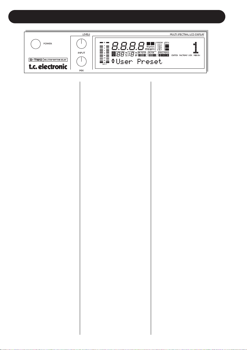
6
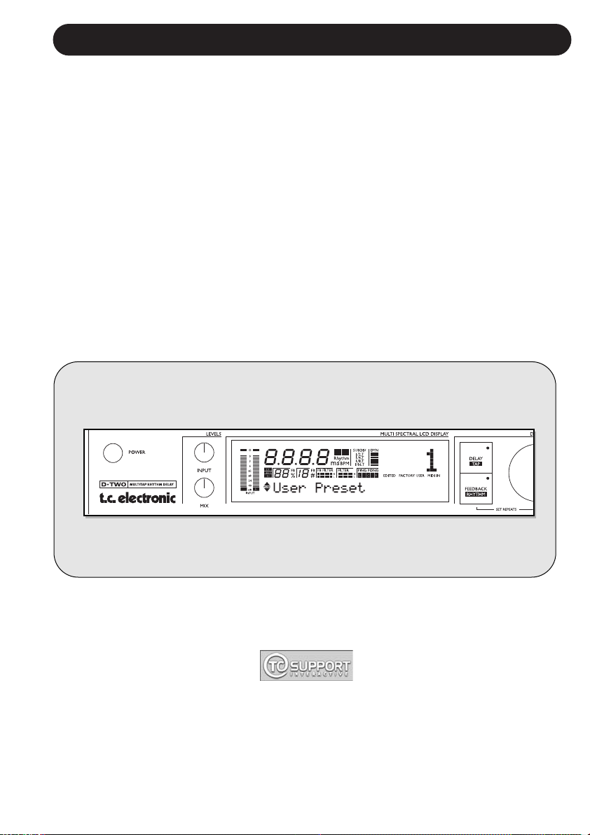
FRONT PANEL OVERVIEW
POWER button
Power on/off.
IN LEVEL knob
Adjusts the Input level.
At center position a relay will
switch the Input circuit
between consumer and pro
level. This will insure optimal
Input Gain range and superb
“signal to noise” ratio is
achieved.
MIX knob
Adjusts the global mix between
dry and wet signal. Fully
clockwise position is 100%
effect.
IN meters
The IN peak meter shows the
Input level of left and right
channels. The meter range is:
0, -3, -6 ,-12, -18, -24, -40dB.
OVERLOAD LEDS
The OVERLOAD LEDs
indicate one of two situations:
- The Input level is too hot
and therefore overloading.
- There is an internal DSP
overflow.
The OVERLOAD LED is lit
when 1 sample is @ 0dBFS.
DELAY TIME indicator
The DELAY TIME indicator can
display Delay time in either ms
(milliseconds) or BPM (Beats
Per Minute). This is selected in
the Setup menu. The ms or
the BPM icon next to the Delay
time will be lit accordingly.
The tempo is also indicated via
the blinking TEMPO/RHYTHM
indicator.
SUBDIVISION indicator
The selected subdivision
determines the recalculation of
the tapped tempo. Example:
At 120BPM you tap 1/4 notes.
The tapped time equals
500ms. If the Subdivision is
set to 1/8, the D•TWO now
recalculates the Delay time to
250ms.
DYNAMIC meter
Indicates the gain reduction on
the Delay Output when using
the Dynamic Delay algorithm.
EDITED icon
This icon will be lit as soon as
the current recalled preset has
been modified.
FACTORY/USER icon
Shows whether you are
operating in the Factory or the
User bank.
MIDI IN icon
Indicates the presence of
incoming MIDI information.
SAMPLE RATE indicator
The SAMPLE RATE indicator
shows the clock source and
the incoming master clock.
The “DI” icon will be blinking if
no clock or unacceptable clock
is found.
FEEDBACK %
The amount of level fed back
to the Delay line. Indicates the
Decay time of the Delay
repeats.
FEEDBACK #
The exact number of repeats.
FB FILTER LEDS
Indicates the Feedback High
and Low Cut filter setting.
FILTER LEDS
Indicates the overall High and
Low Cut filter setting.
PINGPONG LEDS
Indicates the panning currently
processed.
7
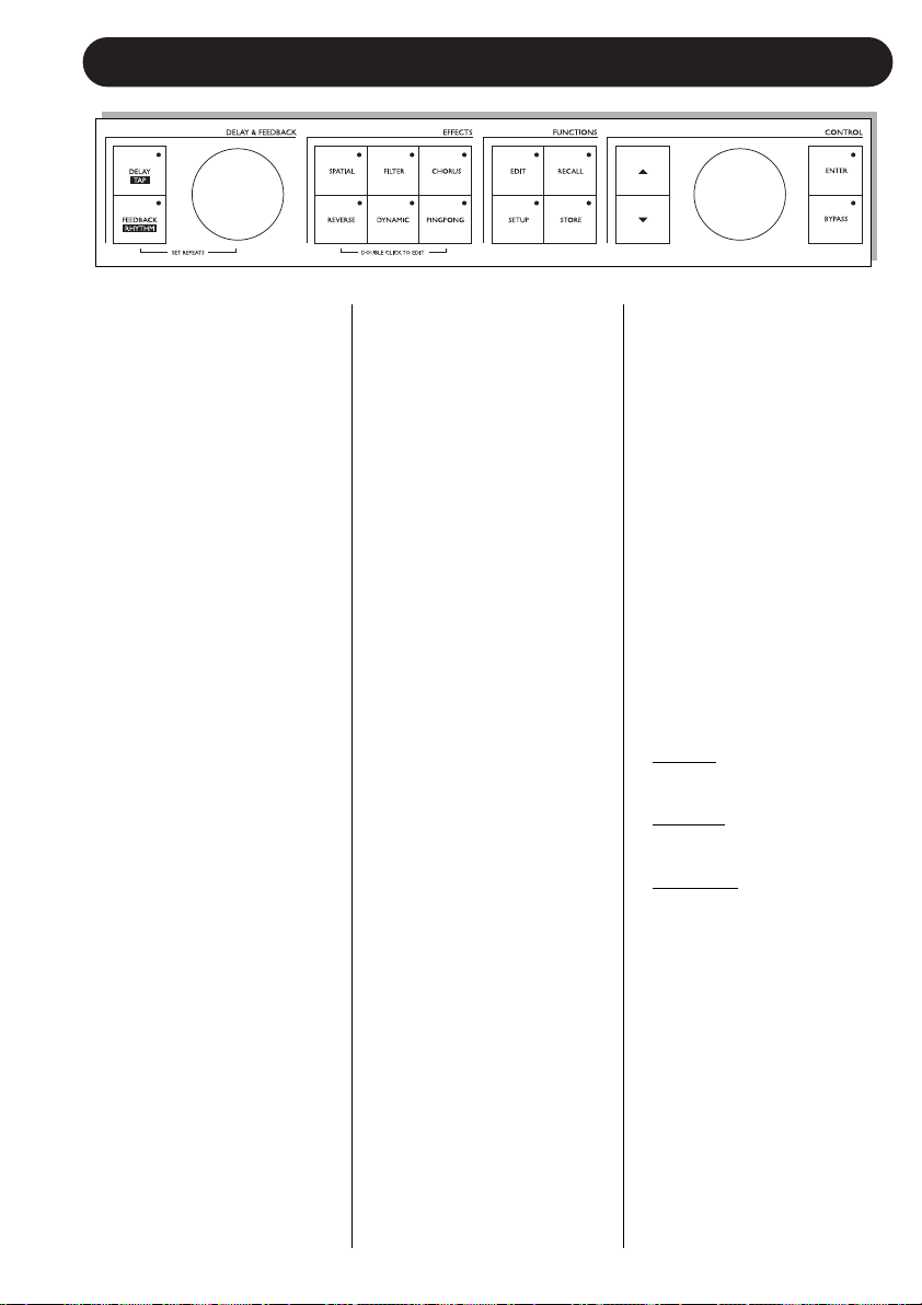
FRONT PANEL OVERVIEW
DELAY/TAP key
This key has two main
functions:
- When the DELAY key LED
is lit, the DELAY wheel can
be used to adjust the Delay
time.
- When the key is tapped the
D•TWO measures the time
between the last two taps
and the Delay time is
calculated according to the
selected subdivision.
FEEDBACK/RHYTHM key
This key has three main
functions:
- When the LED is lit the
DELAY wheel is changing
the Feedback level or %.
- When the key is pressed
and held, the DELAY wheel
changes the number of
repeats.
- Tap a rhythm pattern using
this key. A rhythm pattern
can consist of up to 10 taps.
DELAY & FEEDBACK wheel
Sets the Delay time or
Feedback depending on what
is selected.
SPATIAL key
Enables/disables the Spatial
function. Double click shortcuts
to the Spatial parameters.
Options are:
- Left channel offset
+/-200ms.
- Phase reverse any channel.
FILTER key
Enables/disables the Filter
functions. Double click
shortcuts to the High and Low
Cut filter parameters.
CHORUS key
Enables/disables the Chorus.
Double click shortcuts to the
Chorus parameters.
REVERSE key
Enables/disables the Reverse
Delay. Double click shortcuts
to the Reverse Delay
parameters.
DYNAMIC key
Enables/disables the Dynamic
Delay. Double click shortcuts
to the Dynamic Delay
parameters.
PING PONG key
Enables/disables the PingPong
functions. Double click
shortcuts to the PingPong
parameters.
EDIT key
Enters the general Edit list.
This is where all preset
processing parameters are
located. Use the ARROW keys
to select parameters.
RECALL key
Selects the Recall menu.
SETUP key
Enters the Setup menu.
This is where all I/O and
global parameters are located.
STORE key
Selects the Store menu.
Presets can be stored in the
User bank only. Location is
selected using the
CONTROL wheel. Operation is
confirmed using ENTER.
ARROW UP/DOWN keys
Are used to move the cursor
around in the display.
CONTROL wheel
Is used to change values.
ENTER key
Press to confirm operations.
BYPASS key
Bypasses the unit. There are
three different Bypass modes.
- 0% Mix:
Input signal is
passed directly to the
Output. -
FX Input: Input bypass
allowing the effects to ring
out.
- FX Output: Kills the effect
but keeps the direct signal
level.
The Bypass mode is selected
in the Setup menu.
8
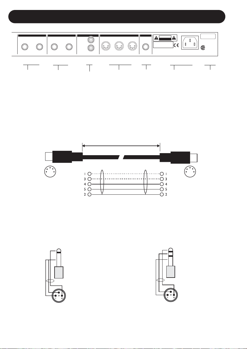
REAR PANEL
IN
UL6500
EN/IEC60065
PROFESSIONALAUDIO EQUIPMENT
THRU
INLEFT LEFTRIGHT RIGHT
OUT
MIDIBALANCED INPUTS BALANCED OUTPUTS DIGITALI/O PEDAL
DI
DO
S/PDIF
SERIAL NO.
TYPE:MAN001
TCELECTRONIC
MADEIN THAILAND
WARNING
TOREDUCE THE RISK OF FIRE OR ELECTRIC
SHOCKDO NOT EXPOSE THISEQUIPMENTTO
RAINOR MOISTURE
AVIS:
RISQUEDE CHOC ELECTRIQUE-NE PAS
OUVRIR.
100-240VAC
50-60Hz,15W
CAUTION
R
CUS
THISCLASS B DIGITAL DEVICE MEETS ALL REQUIREMENTS OFTHECANADIAN INTERFERENCE-
CAUSINGEQUIPMENT REGULATIONS AND COMPLIES WITH PART 15 OF THE FCC RULES.
OPERATIONSUBJECT TO CONDITIONS STATED IN THE MANUAL.
RISKOF ELECTRIC SHOCK
DONOT OPEN
Balanced
Jack
Analog
Inputs
Pedal
Input
MIDI
In/Out/Thru
Balanced
Jack
Analog
Outputs
Digital
S/PDIF
Input/
Output
Power
Input
100 - 240V
Serial
Number
Sleeve - Pin 1 (Ground)
Tip - Pin 2 (Hot)
Ring - Pin 3 (Cold)
Sleeve - Pin 1 (Ground)
Tip - Pin 2 (Hot)
Sleeve - Pin 3 (Cold)
Jack (unbalanced) - XLR
Jack (balanced) - XLR
TIP
RING
GND
TIP
GND
MIDI Cable
DIN CONNECTOR
5POLE - MALE
45 degrees
DIN CONNECTOR
5POLE - MALE
45 degrees
max. 10m
SHIELDED CABLE (3 or 5 wires + screen)
(Use Left Input
for Mono
connection)
 Loading...