


G•MAJOR 2
GUITAR EFFECTS PROCESSOR
User’s Manual
IMPORTANT SAFETY INSTRUCTIONS
The lightning flash with an arrowhead symbol within an equilateral triangle is intended to alert the user to the presence of uninsulated “dangerous voltage” within the product’s enclosure that may be of sufficient magnitude to constitute a risk of electric shock to persons.
The exclamation point within an equilateral triangle is intended to alert the user to the presence of important operating and maintenance (servicing) instructions in the literature accompanying the product.
1 Read these instructions.
2 Keep these instructions.
3 Heed all warnings.
4 Follow all instructions.
5 Do not use this apparatus near water.
6 Clean only with dry cloth.
7 Do not block any ventilation openings. Install in accordance with the manufacturer’s instructions.
8 Do not install near heat sources such as radiators, heat registers, stoves, or other apparatus (including amplifiers) that produce heat.
9 Do not defeat the safety purpose of the polarized or grounding-type plug. A polarized plug has two blades with one wider than the other. A grounding type plug has two blades and a third grounding prong. The wide blade or the third prong are provided for your safety. If the provided plug does not fit into your outlet, consult an electrician for replacement of the obsolete outlet.
10 Protect the power cord from being walked on or pinched particularly at plugs, convenience receptacles, and the point where they exit from the apparatus.
11 Only use attachments/accessories specified by the manufacturer.
12 Use only with the cart, stand, tripod, bracket, or table specified by the manufacturer, or sold with the apparatus. When a cart is used, use caution when moving the cart/apparatus combination to avoid
injury from tip-over.
13 Unplug this apparatus during lightning storms or when unused for long periods of time.
14 Refer all servicing to qualified service personnel. Servicing is required when the apparatus has been damaged in any way, such as power-supply cord or plug is damaged, liquid has been spilled or objects have fallen into the apparatus, the apparatus has been exposed to rain or moisture, does not operate normally, or has been dropped.
Warning!
• To reduce the risk of fire or electrical shock, do not expose this equipment to dripping or splashing and ensure that no objects filled with liquids, such as vases, are placed on the equipment.
• This apparatus must be earthed.
• Use a three wire grounding type line cord like the one supplied with the product.
• Be advised that different operating voltages require the use of different types of line cord and attachment plugs.
• Check the voltage in your area and use the correct type. See table below:
|
|
Voltage |
Line plug according to |
|
standard |
|
|
110 to 125V |
UL817 and CSA C22.2 no 42. |
220 to 230V |
CEE 7 page VII, SR section |
|
107-2-D1/IEC 83 page C4. |
|
|
240V |
BS 1363 of 1984. Specification |
|
for 13A fused plugs and |
|
switched and unswitched |
|
socket outlets. |
• This equipment should be installed near the socket outlet. Disconnection of the device should be easily possible at any time.
• To completely disconnect this apparatus from AC mains, disconnect the power supply cord from the AC receptacle.
• The mains plug of the power supply shall remain readily operable.
• Do not install in a confined space.
• Do not open the unit – risk of electric shock inside.
Caution:
You are cautioned that any change or modifications not expressly approved in this manual could void your authority to operate this equipment.
Service
• There are no user-serviceable parts inside.
• All service must be performed by qualified personnel.
ENGLISH
a

EMC & CERTIFICATE OF CONFORMITY
EMC/EMI
This equipment has been tested and found to comply with the limits for a Class B Digital device, pursuant to part 15 of the FCC rules.
These limits are designed to provide reasonable protection against harmful interference in residential installations. This equipment generates, uses and can radiate radio frequency energy and – if not installed and used in accordance with the instructions – may cause harmful interference to radio communications. However, there is no guarantee that interference will not occur in a particular installation. If this equipment does cause harmful interference to radio or television reception – which can be determined by turning the equipment off and on –, the user is encouraged to try correcting the interference by one or more of the following measures:
• Reorient or relocate the receiving antenna.
• Increase the separation between the equipment and the receiver.
• Connect the equipment to an outlet on a circuit different from the one to which the receiver is connected.
• Consult the dealer or an experienced radio/TV technician for help.
For the customers in Canada:
This Class B digital apparatus complies with Canadian ICES-003. Cet appareil numérique de la classe B est conforme à la norme NMB-
003 du Canada.
Certificate of Conformity
TC Electronic A/S, Sindalsvej 34, 8240 Risskov, Denmark, hereby declares on own responsibility that the following product:
G-Major 2 – Guitar Effects Processor
– that is covered by this certificate and marked with CE-label conforms with following standards:
EN 60065 Safety requirements for mains (IEC 60065) operated electronic and
related apparatus for household and similar general use
EN 55103-1 Product family standard for audio, video, audio-visual and entertainment lighting control apparatus for professional use. Part 1: Emission.
EN 55103-2 Product family standard for audio, video, audio-visual and entertainment lighting control apparatus for professional use. Part 2: Immunity.
With reference to regulations in following directives:
73/23/EEC, 89/336/EEC
Issued in Risskov, January 2009
Anders Fauerskov
Chief Executive Officer
b

TABLE OF CONTENTS
INTRODUCTION
Important Safety Instructions . . . . . . . .a-b
Table of Contents . . . . . . . . . . . . . . . . . .3
Introduction . . . . . . . . . . . . . . . . . . . . . . .4
Front Panel Overview . . . . . . . . . . . . . . .6
Rear Panel Overview . . . . . . . . . . . . . . .8
Signal Flow Diagram . . . . . . . . . . . . . . . .9
Basic Setups . . . . . . . . . . . . . . . . . . . . .10
OPERATION
The Display . . . . . . . . . . . . . . . . . . . . . .12
Recall . . . . . . . . . . . . . . . . . . . . . . . . . .13 Edit . . . . . . . . . . . . . . . . . . . . . . . . . . . .13 Store . . . . . . . . . . . . . . . . . . . . . . . . . . .13 Preset Backup via MIDI . . . . . . . . . . . .14
Global Menu . . . . . . . . . . . . . . . . . . . . .15
MIDI . . . . . . . . . . . . . . . . . . . . . . . . . . .18
MOD Menu . . . . . . . . . . . . . . . . . . . . . .19
External Control . . . . . . . . . . . . . . . . . .20 External Control Using Modifiers . . . . .20 The Tuner . . . . . . . . . . . . . . . . . . . . . . .22 Relays . . . . . . . . . . . . . . . . . . . . . . . . . .24 Routings . . . . . . . . . . . . . . . . . . . . . . . .26 Getting Started / “How to…” . . . . . . . . .27
EFFECT BLOCKS
Introduction . . . . . . . . . . . . . . . . . . . . . .29
Effects Menu – Basic operation . . . . . .29
Gate & EQ
Noise Gate . . . . . . . . . . . . . . . . . . . . . .30
EQ . . . . . . . . . . . . . . . . . . . . . . . . . . . . .30
Filter
WahWah . . . . . . . . . . . . . . . . . . . . . . . .31
TouchWah . . . . . . . . . . . . . . . . . . . . . . .31
Auto wah . . . . . . . . . . . . . . . . . . . . . . . .32
Resonance Filter . . . . . . . . . . . . . . . . . .32
Touch Resonance Filter . . . . . . . . . . . .33
Tremolo . . . . . . . . . . . . . . . . . . . . . . . . .33
Panner . . . . . . . . . . . . . . . . . . . . . . . . .34
Compressor
Compressor . . . . . . . . . . . . . . . . . . . . .35
Pitch
Detune . . . . . . . . . . . . . . . . . . . . . . . . .36
Whammy . . . . . . . . . . . . . . . . . . . . . . . .36
Octaver . . . . . . . . . . . . . . . . . . . . . . . . .37
Pitch Shifter . . . . . . . . . . . . . . . . . . . . . .38
Intelligent Pitch Shifter . . . . . . . . . . . . .39
Modulation
Classic Chorus . . . . . . . . . . . . . . . . . . .40
Advanced Chorus . . . . . . . . . . . . . . . . .40
Tri-Chorus Normal . . . . . . . . . . . . . . . . .41
Tri-Chorus Asymmetric . . . . . . . . . . . . .41
Classic Flanger . . . . . . . . . . . . . . . . . . .42
Advanced Flanger . . . . . . . . . . . . . . . . .43
Through Zero Flanger negative . . . . . .43 Through Zero Flanger positive . . . . . . .43 Vibrato . . . . . . . . . . . . . . . . . . . . . . . . . .44 Vintage Phaser . . . . . . . . . . . . . . . . . . .45 Smooth Phaser . . . . . . . . . . . . . . . . . . .45 Vintage Univibe . . . . . . . . . . . . . . . . . . .46 Modern Univibe . . . . . . . . . . . . . . . . . . .46
Delay
Ping pong . . . . . . . . . . . . . . . . . . . . . . .47
Dynamic . . . . . . . . . . . . . . . . . . . . . . . .48
Dual . . . . . . . . . . . . . . . . . . . . . . . . . . . .48
Reverse . . . . . . . . . . . . . . . . . . . . . . . . .48
Reverb
Spring . . . . . . . . . . . . . . . . . . . . . . . . . .49
Hall . . . . . . . . . . . . . . . . . . . . . . . . . . . .49
Room . . . . . . . . . . . . . . . . . . . . . . . . . .49
Plate . . . . . . . . . . . . . . . . . . . . . . . . . . .49
APPENDIX
MIDI Implementation . . . . . . . . . . . . . . .51
Technical Specifications . . . . . . . . . . . .52
Frequently Asked Questions . . . . . . . . .53
ENGLISH
|
|
|
TC Electronic, Sindalsvej 34, DK-8240 Risskov |
Multilingual Version |
Rev 1 – SW – V 1 |
|
Prod. No: E60511011 |
3 |

INTRODUCTION
Congratulations on the purchase of your G-Major 2 Effects Processor.
Maybe you have never used a multi-effects processor with your guitar rig before. In this case you might be wondering whether you now have days of work ahead of you until G-Major 2 finally behaves as expected and adds to your creativity. But there’s really no need to panic!
With the presets that come with G-Major 2, your basic needs are most likely covered, and you will be set to go within minutes.
But chances are that you’ll want to go beyond Factory presets and customize G-Major 2 to your needs – and that won’t be a hassle either.
“Stomp Box” Setup
If you are used to working with several serially connected pedal effects (“stomp boxes”), you might want to use G-Major 2 for a similar setup and enjoy its high quality effects. To do so, simply connect a MIDI pedal capable of sending MIDI Control Change messages to G-Major 2. Make some basic settings, and you can use this setup just like a bunch of regular stomp boxes where you simply turn effects on and off as required.
Preset Setup – for ultimate changes in sounds
Another approach would be to create unique presets for each sound, which you can then access by simply pressing a button on a MIDI foot-controller.
Or you could combine this preset approach with the on/off stomp box setup mentioned above. Channel Switching
Changing your sound from a crisp, dry rhythm sound to an overdriven lead sound will (in addition to changing your effects preset) often involve switching your preamp’s or combo’s channels. If you want to switch amp channels via MIDI, you will normally need to purchase a separate MIDI switching system. Not so with G-Major 2. With G-Major 2’s built-in Relay Switch, you can switch between up to four channels on your preamp/combo.
Modifiers – Instant Parameter Control
If the methods outlined above still don’t give you the flexibility you are looking for, instant parameter control via G-Major 2’s Modifier section is probably the answer. Many algorithm parameters can be assigned to external MIDI controllers or an expression pedal. The possibilities here are endless.
With an expression pedal, you cannot only control your effects’ level settings, you could also change e.g. the Panning Speed. Or how about using the expression pedal as a customized
Whammy pedal?
4

INTRODUCTION
G-Major vs. G-Major 2 – what’s the deal?
Well – why not make a great product even better? With an even easier to operate front panel and a bunch of new effects, it made good sense for TC to relaunch one of our most successful products as G-Major 2. Just check out these features:
•Univibe
•Tri-Chorus
•Through-Zero Flanger
•Retuned TC Electronic reverbs
•New filter/Wah block ported 1:1 from the G-System
•Reverse Delay
•Intelligent pitch shifting
•Modulated delays
•PC/Mac editor
•Relay switching
About this manual
You can always download the latest revision of this manual in several languages from our website www.tcelectronic.com.
If you need additional information and support, be sure to visit TC Support Interactive – this service can also be accessed via www.tcelectronic.com.
ENGLISH
5
FRONT PANEL OVERVIEW
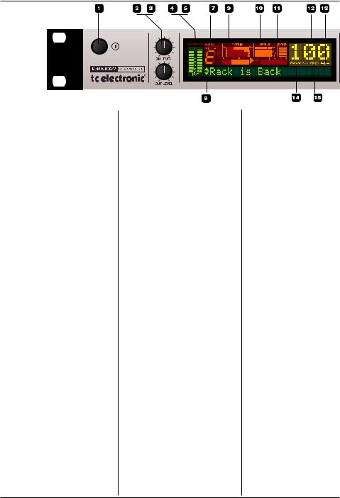
1 – POWER button
On/off switch for the unit.
2 – INPUT LEVEL knob
Adjusts the input level.
3 – OUTPUT LEVEL knob
Adjusts the output level.
4 – INPUT meters
Peak meter showing the input level. The meter range is: 0, -3, - 6 , -12, -18, -24, -40 dB.
5 – INPUT OVERLOAD LEDs
The OVERLOAD LEDs indicate one of two situations: Either the input level is too hot (and therefore overloading the input stage), or there is an internal DSP overflow. When these LEDs light up, reduce the input level slightly.
8 – TUNER
The tuner of G-Major 2 is always active. When the played note is in tune, both arrows will be lit.
9 – THE MATRIX
You can route G-Major 2’s effect blocks in four different ways: Serial, Seria l2, Semi Parallel and Parallel. The Matrix illustrates the structure of the currently used routing.
10 – LEVELS section
These Peak Program Meters
(PPM) indicate the in/out levels of the effect block you are currently editing, as well as the current mix level of the effect.
IN Meter:
Indicates the signal level at the effect block’s input.
OUT Meter:
Indicates the signal level at the effect block’s output.
MIX Meter
Indicates the mix setting of the effect block being edited.
11 – DAMP
When both the Noise Gate and the Compressor are in use, the DAMP indicator will indicate the Noise Gate attenuation when no input signal is present and the applied compression when an input signal is present.
12 – PRESET NUMBER
When the digits are lit steadily, they represent the currently recalled preset. When previewing/scrolling through presets, the digits will blink until you recall the preset by pressing the RECALL key.
13 – EDITED
When this LED is lit, the currently recalled preset has been edited but not yet stored.
14 – FACTORY/USER
Indicates whether you are operating in the Factory bank or in the User bank.
15 – MIDI IN
Indicates incoming MIDI information.
16 – MIX TOGGLE wheel
Turn this wheel to scroll through the mix values of the individual effects.
6
FRONT PANEL OVERVIEW
ENGLISH
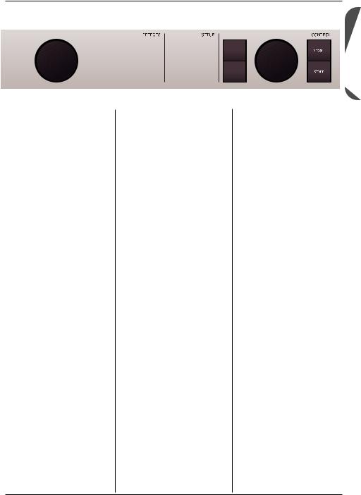
Effect Block Keys
– General information
Pressing an Effect Block key once will activate/deactivate the effect. By pressing a key twice in short succession
(“double-clicking”), you enter the Edit menu for the effect. When the LED of a key is lit, this particular effect block is active.
17 to 24 – EFFECT ON/OFF & ACCESS keys
On/off and access keys for the effect blocks. Press a key once to activate/deactivate an effect and double-click it to edit that effect’s parameters.
25 – GLOBAL key
Press to access global parameters and functions such as Kill-dry, Pedal Calibration,
Tuner Reference, FX Mute
Mode and more.
26 – MOD key
Press to access the Modifier section. This is where you set up external control of parameters.
27 – MIDI key
Press to access all MIDI parameters.
28 – BYPASS key
Press to bypass all effects. Press and hold for approximately one second to mute outputs, e.g. for silent tuning.
29/30 – UP/DOWN keys
Up/down keys for navigation in the display menus.
31 – ADJUST & ENTER
Wheel
Use this wheel to set the value of the currently selected parameter.
When pushed, the wheel acts as an “Enter” key.
32 – RECALL key
Press RECALL to initiate a preset recall operation. Turn the ADJUST wheel to select a preset. Then press the
ADJUST wheel (pressing the wheel acts as “Enter”) or press the RECALL key to confirm your selection.
33 – STORE key
Press the STORE key once to begin storing a preset.
First select a storage location using the ADJUST wheel.
Then press the ADJUST wheel twice to finish the storage procedure (pressing the wheel acts as “Enter”).
You can change the name of the preset before storing it. To do so, use the UP/DOWN key to select characters. Use the ADJUST wheel to select the character you want to change. When you have set the name, press the ADJUST wheel twice to finish the storage procedure.
7
REAR PANEL
|
|
|
|
|
|
|
|
|
|
|
|
|
|
|
|
|
|
|
|
|
|
|
|
|
|
|
|
|
|
|
|
|
|
|
|
|
|
|
|
|
|
|
|
|
|
|
|
|
|
|
|
|
|
|
|
|
|
|
|
|
|
|
|
|
|
|
|
|
|
|
|
|
|
|
|
|
|
|
|
|
|
|
|
|
|
|
|
|
|
|
|
|
|
|
|
|
|
|
|
|
|
|
|
|
|
|
|
|
|
|
|
|
|
|
|
|
|
|
|
|
|
|
|
|
|
|
|
|
|
|
|
|
|
|
|
|
|
|
|
|
|
|
|
|
|
|
|
|
|
|
|
|
|
|
|
|
|
|
|
|
|
|
|
|
|
|
|
|
|
|
|
|
|
|
|
|
|
|
|
|
|
|
|
|
|
|
|
|
|
|
|
|
|
|
|
|
|
|
|
|
|
|
|
|
|
|
|
|
|
|
|
|
|
|
|
|
|
|
|
|
|
|
|
|
|
|
|
|
|
|
|
|
|
|
|
|
|
|
|
|
|
|
|
|
|
|
|
|
|
|
|
|
|
|
|
|
|
|
|
|
|
|
|
|
|
|
|
|
|
|
|
|
|
|
|
|
|
|
|
|
|
|
|
|
|
|
|
|
|
|
|
|
|
|
|
|
|
|
|
|
|
|
|
||||||
Switch |
|
Balanced |
Balanced |
|
|
MIDI |
External |
|
Power |
|
||||||||||||||||||||
Out |
|
Jack |
Jack |
|
|
In, Out, Thru |
Control |
|
input |
|
||||||||||||||||||||
Relay |
|
Analog |
Analog |
|
|
|
|
|
|
|
|
|
|
|
100 to 240V |
|
||||||||||||||
Jack |
|
inputs |
outputs |
|
|
|
|
|
|
|
|
|
|
|
|
|
|
|
|
|
|
|||||||||
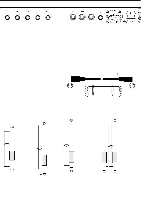
Balanced vs. regular Audio Cables
The analog input and output connectors on G-Major 2 are balanced ¼" jacks. To achieve the best possible connection to balanced equipment, use balanced cables. However, most guitar equipment is NOT balanced, and you will generally have no problems when using standard mono-to- mono cables as illustrated below.
MIDI Cable
DIN CONNECTOR |
|
|
|
|
DIN CONNECTOR |
|||
5POLE – MALE |
|
|
|
|
5POLE – MALE |
|||
45 degrees |
|
SHIELDED CABLE (3 or 5 wires + screen) 45 degrees |
||||||
|
|
|
|
|
|
|
|
|
|
|
|
|
max. 10m |
|
|
|
|
|
|
|
|
|
|
|
|
|
|
|
|
|
|
|
|
|
|
|
|
|
|
|
|
|
|
|
|
|
|
|
|
|
|
|
|
|
|
|
|
|
|
|
|
|
Jack Cable |
Jack Cable |
Relay Jack Cable |
Relay Jack Cable |
|||||||||||||||||||
Mono to Mono |
Stereo to Mono |
– Stereo Jack Type |
– Y-Splitter Type |
|||||||||||||||||||
|
|
|
|
|
|
|
|
|
|
TIP |
|
|
|
|
|
TIP |
|
|
|
|
|
TIP |
|
|
|
TIP |
|
|
|
|
|
|
|
|
|
|
|
RING |
|
|
|
|
|
RING |
|
|
|
|
|
|
|
|
|
|
RING |
|
|
|
|
|
GND |
|
|
|
|
|
GND |
|
|
|
|
GND |
|
|
|
|
|
|
GND |
|
|
|
|
|
|
|
|
|
|
|
|
|
|
|
|
|
|
|
|
|
|
|
|
|
|
|
|
|
|
|
|
|
|
|
|
|
|
|
|
|
|
|
|
|
|
|
|
|
|
|
|
|
|
|
|
|
|
|
|
|
|
|
|
|
|
|
|
|
|
|
|
|
|
|
|
|
|
|
|
|
|
|
|
|
|
|
|
|
|
|
|
|
|
|
|
|
|
|
|
|
|
|
|
GND |
|
GND |
|
|
TIP |
GND |
GND |
GND |
|
|
RING |
|||
|
TIP |
TIP |
TIP |
TIP |
8
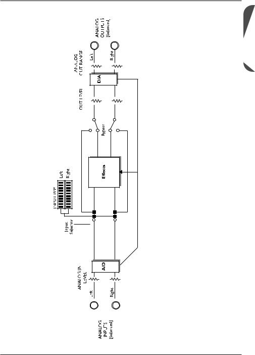
SIGNAL FLOW DIAGRAM
ENGLISH
9
BASIC SETUPS
Connecting and setting up G-Major 2
There are numerous ways of hooking up guitar rigs. On the following pages, we present some of the most commonly used setups. We recommend using serial setups, where the entire signal passes through G-Major 2. This will give you the maximum benefit from all effect algorithms.
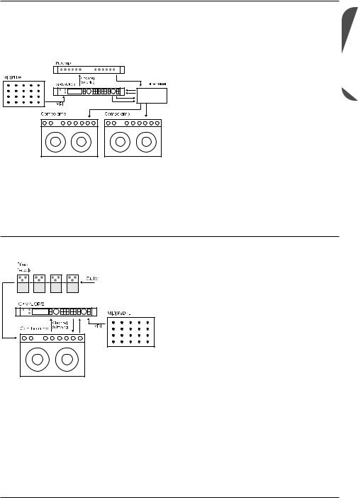
Serial setup with preamp and power amp
• Connect the output of your preamp to the input of G-Major 2.
• Connect the output of G-Major 2 to the input of your power amp.
• If you want to switch preamp channels with
G-Major 2, connect the SWITCH OUT jack on G-Major 2 to the channel switching jacks on your preamp. This is not required for MIDIcontrollable preamps.
Serial setup with a preamp and one or two combo amps
• Connect the output of your preamp to the input of G-Major 2.
• Connect the output of G-Major 2 to either the input or the Loop Return of the combo or combos.*
• If you want to switch preamp channels with
G-Major 2, connect the SWITCH OUT jack on
G-Major 2 to the channel switching jacks on your preamp. This is not required for MIDIcontrollable preamps.
* Using the return jack of the combo’s effect loop will in most cases give you a setup similar to the power-amp setup described above.
Using the regular input on the combo gives you a “double-preamp” setup, where you can use the tone controls on the combo to color your sound. This introduces more noise than when using the Loop Return connection, but has become a popular setup with amplifiers like Vox AC 30, Fender Bassman etc.
10
Connecting and setting up G-Major 2
BASIC SETUPS
Parallel setup using a line mixer
• Connect the output of your preamp to an input on the line mixer.
• If you want to switch preamp channels with
G-Major 2, connect the SWITCH OUT jack on G-Major 2 to the channel switching jacks on your preamp. This is not required for MIDI-controllable preamps.
• Connect the send jacks of your line mixer’s effect loop to the inputs of G-Major 2. Connect the outputs of G-Major 2 to the return jacks of your line mixer’s effect loop.
• Connect the line mixer’s main outputs to your amplification system.
This illustration shows combo amplifiers – but of course, you could also use a power amp here. Likewise, the preamp shown in the illustration could easily be the preamp section of a combo amplifier.
Combined setup with regular effect pedals, a G-Major 2 and a MIDI pedal
• Connect the send jack of the combo’s effect loop to the input of G-Major 2.
• Connect the output of G-Major 2 to the return jack of the combo’s effect loop.
• Connect your guitar to the input of your
(first) effect pedal. Connect the output of the
(last) effect pedal to the input of the combo as usual.
• If you wish to switch presets on G-Major 2
(which may include switching the channels of your preamp/combo), you should also connect a MIDI pedal to G-Major 2 and use the Relay Switching function.
ENGLISH
11

THE DISPLAY
Overload |
Matrix – indication of |
Block levels – |
Damp |
LEDs |
currently used Routing |
In/Out and Mix |
Compression/ |
|
|
|
Noise Gate |
|
|
|
Preset |
|
|
|
Number |
|
|
|
Indicators |
|
|
|
for: |
|
|
|
Received |
|
|
|
MIDI data |
|
|
|
Factory/User |
Input meter |
Detected input pitch |
Tuner |
preset bank |
Edited |
Input Meters |
The Matrix |
|
|
|
|
|
|
|
|
|
|
|
|||||||
These are peak meters showing the current |
G-Major 2 gives you four different options for |
||||||||||||||||||
input level. The meter range is: 0, -3, -6, -12, - |
routing its effect blocks: Serial, Serial 2, Semi |
||||||||||||||||||
18, -24, -40 dB. |
Parallel and Parallel. The Matrix indicates which |
||||||||||||||||||
|
of the three routings is currently being used. |
||||||||||||||||||
To set the correct input level: |
|
|
|
|
|
|
|
|
|
|
|
|
|
|
|
|
|
|
|
|
|
|
|
|
|
|
|
|
|
|
|
|
|
|
|
|
|
||
• Select the “loudest” sound – i.e., the sound |
|
|
|
|
|
|
|
|
|
|
|
|
|
|
|
|
|
|
|
|
|
|
|
|
|
|
|
|
|
|
|
|
|
|
|
|
|
||
containing the most dynamic content on the |
|
|
|
|
|
|
|
|
|
|
|
|
|
|
|
|
|
|
|
|
|
|
|
|
|
|
|
|
|
|
|
|
|
|
|
|
|
||
|
|
|
|
|
|
|
|
|
|
|
|
|
|
|
|
|
|
||
equipment you are feeding G-Major 2 with, |
Serial |
Serial 2 |
|||||||||||||||||
e.g. your preamp. This will probably be a |
|||||||||||||||||||
|
|
|
|
|
|
|
|
|
|
|
|
|
|
|
|
|
|
||
clean sound. |
|
|
|
|
|
|
|
|
|
|
|
|
|
|
|
|
|
|
|
• Adjust the input level on G-Major 2 so that |
|
|
|
|
|
|
|
|
|
|
|
|
|
|
|
|
|
|
|
|
|
|
|
|
|
|
|
|
|
|
|
|
|
|
|
|
|
||
|
|
|
|
|
|
|
|
|
|
|
|
|
|
|
|
|
|
||
the -3 dB LED flashes frequently and the -0 |
|
|
|
|
|
|
|
|
|
|
|
|
|
|
|
|
|
|
|
dB LED flashes only at the very highest |
|
|
|
|
|
|
|
|
|
|
|
|
|
|
|
|
|
|
|
|
|
|
|
|
|
|
|
|
|
|
|
|
|
|
|
|
|
||
levels. |
Semi Parallel |
Parallel |
|||||||||||||||||
Input Overload LEDs |
|
|
|
|
|
|
|
|
|
|
|
|
|
|
|
|
|
|
|
The OVERLOAD LEDs light up in two |
Levels Section – In/Out/Mix |
||||||||||||||||||
situations: |
|||||||||||||||||||
These readouts refer only to the block currently |
|||||||||||||||||||
Either the input level is too hot and therefore |
|||||||||||||||||||
being edited. |
|
|
|
|
|
|
|
|
|
|
|
||||||||
overloading the input stage, or there is an |
PPM – Peak Program Meter: |
||||||||||||||||||
internal DSP overflow. Reduce either the output |
|||||||||||||||||||
of the device feeding G-Major 2 or reduce the |
Indicates the level of the block currently being |
||||||||||||||||||
input gain on G-Major 2 using the IN LEVEL |
edited. |
|
|
|
|
|
|
|
|
|
|
|
|||||||
knob. |
In Meter: |
|
|
|
|
|
|
|
|
|
|
|
|||||||
The Tuner |
Indicates the signal level at the input of the |
||||||||||||||||||
G-Major 2 is equipped with a tuner, which is |
block currently being edited. |
||||||||||||||||||
always active. When both horizontal arrows are |
Out Meter: |
|
|
|
|
|
|
|
|
|
|
|
|||||||
lit, the played string is in tune. |
Indicates the signal level at the output of the |
||||||||||||||||||
|
block currently being edited. |
||||||||||||||||||
Mix Meter:
Indicates the level of the mixed signal (dry and edited signal) within the block currently being edited.
12

Damp
When both the Noise Gate and the Compressor are in use, the DAMP indicator will indicate the
Noise Gate attenuation while no input signal is present and the applied compression when an input signal is present.
Preset Number
When the digits are lit steadily, they represent the number of the currently recalled preset. When you scroll through G-Major 2’s presets
(called “previewing”) by using the ADJUST wheel, the digits will blink until you recall a preset by pressing the RECALL key.
Edited
When the “Edited” indicator is lit, the currently recalled preset has been edited, but not yet stored.
Factory/User
These indicators show whether you are operating in the Factory preset bank or in the
User preset bank.
Preset types
User presets (RAM)
User presets can be edited and stored in any of the 100 User locations.
Factory Presets (ROM)
G-Major 2 holds 100 Factory presets. Factory presets can be edited and stored in any User location. You cannot store presets to the
Factory preset bank, as it is “read only” memory.
Recalling presets
Recalling a preset means loading/activating a preset.
• Press the RECALL key to enter the RECALL menu.
• Use the ADJUST wheel to preview presets. A blinking preset number indicates that you have not actually recalled the preset yet.
• Press ENTER or RECALL to recall/activate the preset.
Press any other key at any time during previewing to “abort mission” and return to the currently recalled preset.
Previewing and routings:
When previewing a preset with a routing that is different from the routing currently used, the Routing/Matrix LEDs blink.
Editing presets
To edit preset parameters:
• Double-click the key of the effect block that you would like to edit.
• Select the parameter to edit using the arrow
UP/DOWN keys. Change parameter values using the ADJUST wheel.
• See the following section for instructions on how to store a preset.
Storing presets
Storing a preset without changing its name:
• Press the STORE key.
If the preset you are about to store is a
Factory preset, G-Major 2 will suggest the first available User preset location, but you can select any of the 100 User preset locations using the ADJUST wheel. If the preset you are about to store is a User preset, G-Major 2 suggests the current location of the preset. You can, however,
ENGLISH
13

PRESET HANDLING
store the preset at any of the 100 User locations. Select the location to store the preset to by using the ADJUST wheel.
• Press ENTER twice to confirm the storage operation.
Renaming a preset while storing:
• Press the STORE key.
If the preset you are about to store is a Factory preset, G-Major 2 will suggest the first available User preset location, but you can select any of the 100 User preset locations using the ADJUST wheel. Select the location to store the preset to and press ENTER once.
• To change the preset name:
Use the UP/DOWN keys to move the cursor in the display. Use the ADJUST wheel to select the character at the current cursor position.
• Once you have renamed the preset, press
ENTER twice to store the preset with the new name.
Backing up presets via MIDI
For backup purposes, the User bank can be dumped via MIDI to either a sequencer or to another G-Major 2. This is how to do it:
• Connect the MIDI OUT jack of your G-Major 2 to the MIDI IN jack of either another G-Major 2 or a sequencer (this may also be the MIDI interface of a digital audio workstation).
• Press the MIDI key and select the “Bulk
Dump” function using the UP/DOWN keys.
• When you have connected your G-Major 2 to another G-Major 2, simply press ENTER.
The entire User bank will be copied to the second G-Major 2.
• When you have connected your G-Major 2 to a sequencer, let the sequencer record in
OMNI mode (all channels) and press ENTER on G-Major 2.
G-Major 2 is always ready to receive a MIDI bulk dump.
Simply connect the MIDI OUT jack of the device you are dumping from to the MIDI IN jack of your G-Major 2. If you want to use a User bank that you have previously dumped to a sequencer as described above, simply play back the sequence containing the bulk dump. If dumping from another G-Major 2 – see above!
14

GLOBAL MENU
Introduction
In the Global menu you will find a lot of important parameters, such as Input Type,
Clock, Input/Output Range. These parameters must be set correctly to ensure you get the most out of G-Major 2!
All parameters in the I/O menu are “general” parameters that are not stored as part of G-Major 2 presets.
Basic operation
• Press the GLOBAL key.
• Select parameters using the UP/DOWN keys and change parameter values using the ADJUST wheel.
Kill Dry
Settings: On/Off
We always recommend using G-Major 2 in a serial or loop setup as this will allow you to benefit from all the unit’s effects and features.
If, however, you intend to use G-Major 2 in a parallel setup or in a parallel loop, its Kill Dry function will come in handy.
With Kill Dry activated, no direct signal is passed to the outputs of G-Major 2.
A few comments regarding the Kill Dry function and a parallel setup:
First of all:
• In such a setup, we recommend using the
Parallel routing.
• When the Kill Dry parameter is set to “On”, no clean signal is passed to the outputs, and the
“Mix” parameter changes to “Wet” in all algorithms.
You should also be aware that the way the signal is routed in a parallel loop is similar to the signal path within a mixer. The signal is split:
One part runs unprocessed to the output and never passes the actual effects processor. The other part of the signal is processed within G-Major 2 and summed with the unprocessed signal. Therefore, you will not get to enjoy the benefits from all effects when running a parallel setup. This goes especially for level-based effects such as Tremolo and Panner, but the Chorus/Flanger/ Phaser/Vibrato and Pitch blocks will be affected as well.
Pedal type
Defines up the pedal type used on the Ext. Control ¼" jack. Select between Momentary,
Alternating or Expression/Volume pedal types.
Momentary type pedals are similar to the hold pedals typically used with keyboards (where there is only a connection between tip and ground when the pedal is pressed). Alternating pedal types “stay connected” when pressed and must be pressed again to be deactivated. Use the default setting “Exp/Vol” when working with an Expression pedal.
Pedal Calibrate
To use an expression pedal for controlling
G-Major 2 parameters, G-Major 2 must be calibrated to that specific pedal. This is how you calibrate G-Major 2:
1. Connect your pedal and select the appropriate pedal type (see parameter Pedal
Type).
2. Select “Pedal Calibrate” and press ENTER.
3. Move the pedal to its maximum position (“toe down”) and press ENTER.
4. Move the pedal to its minimum position (“toe up”) and press ENTER.
Your pedal has been calibrated.
Depending on the pedal type you are using, you may be asked to repeat steps
 3 and 4.
ENGLISH
15

GLOBAL MENU
MOD Master
Settings: Preset / Mod
If you are not acquainted with Modifiers, you can read about them in the “Modifiers” section of this manual. In short: Parameter values can be controlled using an external controller, such as a MIDI expression pedal. If you have set up this external controller to control e.g. the Preset Out level, you must decide how you would like G-Major 2 to respond to the position of the expression pedal when you are recalling another preset. This is the purpose of the MOD Master parameter. Setting this option correctly depends very much on what parameter your
Modifier is controlling.
Preset
If MOD Master is set to “Preset”, G-Major will ignore the position of the connected external controller and load the Modifier value stored as part of the preset.
Mod
If MOD Master is set to “Mod”, G-Major will always check the position of the connected external controller when a preset change occurs. G-Major will then respond to this position and ignore the Modifier value for the relevant parameter.
Please note that when you are using the “Mod” option with an expression pedal that is controlling a level parameter, the parameter will jump to the value equivalent to the pedal position next time you move the pedal. This could result in considerable level jumps.
Tuner Ref.
Range: 420 to 460 Hz
Defines the master tune frequency of the builtin tuner. The standard setting is 440 Hz.
Tuner Mode |
|
The Tuner can operate with two different |
|
accuracies. |
|
Fine Tune |
|
Fine Tune provides maximum accuracy. Use |
|
this mode when fine-tuning your guitar. |
|
Coarse |
|
This is a slightly less accurate mode, allowing |
|
for fast results in a live situation. |
|
Tuner Range |
|
Defines the range of the Tuner. Select between |
|
“Guitar”, “Bass” and “7-string Guitar”. The |
|
accuracy of the Tuner depends on the Tuner |
|
Range. Therefore, it is important to set this |
|
parameter according to the instrument you wish |
|
to tune. |
|
Tap Master |
|
Preset: |
The tempo will be set to the value |
|
stored as part of each G-Major 2 |
|
preset. |
Tap: |
The tempo will follow the Global |
|
tapped tempo. |
Tap Unit |
|
This parameter determines whether the tapped |
|
tempo in the Tap Menu should be displayed in |
|
milliseconds (“ms”) or in beats per minute |
|
(“BPM”). |
|
FX Mute |
|
Settings: Hard/Soft |
|
This parameter determines how delay and reverb |
|
effects should be handled during preset changes. |
|
Hard: |
Effects are muted when a preset |
|
change occurs. |
Soft: |
Delays will “spill over”, and reverb |
|
parameters glide smoothly to the |
|
settings in the new preset. |
16
 Loading...