


NOVA System
User’s Manual

IMPORTANT SAFETY INSTRUCTIONS
|
The lightning flash with an arrowhead symbol within |
The exclamation point within an equilateral triangle is |
||||
|
an equilateral triangle is intended to alert the user to |
intended to alert the user to the presence of important |
||||
|
the presence of uninsulated “dangerous voltage” |
operating and maintenance (servicing) instructions in |
||||
|
within the product's enclosure that may be of sufficient |
the literature accompanying the product. |
||||
|
magnitude to constitute a risk of electric shock to persons. |
|
|
|
|
|
|
|
|
|
|
||
1 |
Read these instructions. |
Warning! |
|
|
||
2 |
Keep these instructions. |
• To reduce the risk of fire or electric shock, do not expose |
||||
3 |
Heed all warnings. |
|||||
this apparatus to rain or moisture and objects filled with |
||||||
4 |
Follow all instructions. |
|||||
liquids, such as vases, should not be placed on this |
||||||
5 |
Do not use this apparatus near water. |
|||||
apparatus. |
|
|
||||
6 |
Clean only with dry cloth. |
|
|
|||
• This apparatus must be earthed. |
||||||
7 |
Do not block any ventilation openings. Install in accordance |
|||||
• Use a three wire grounding type line cord like the one |
||||||
|
with the manufacturer's instructions. |
|||||
|
supplied with the product. |
|||||
8 |
Do not install near any heat sources such as radiators, heat |
|||||
• Be advised that different operating voltages require the use |
||||||
|
registers, stoves, or other apparatus (including amplifiers) |
|||||
|
of different types of line cord and attachment plugs. |
|||||
|
that produce heat. |
|||||
|
• Check the voltage in your area and use the correct type. |
|||||
9 |
Do not defeat the safety purpose of the polarized or |
|||||
See table below: |
|
|
||||
|
grounding-type plug. A polarized plug has two blades with |
|
|
|||
|
|
|
|
|
||
|
one wider than the other. A grounding type plug has two |
|
Voltage |
Line plug according to standard |
|
|
|
blades and a third grounding prong. The wide blade or the |
|
|
|
|
|
|
|
110-125V UL817 and CSA C22.2 no 42. |
|
|||
|
third prong are provided for your safety. If the provided plug |
|
|
|||
|
|
|
|
|
||
|
does not fit into your outlet, consult an electrician for |
|
220-230V CEE 7 page VII, SR section |
|
||
|
replacement of the obsolete outlet. |
|
|
107-2-D1/IEC 83 page C4. |
|
|
10 |
Protect the power cord from being walked on or pinched |
|
240V |
BS 1363 of 1984. |
|
|
|
particularly at plugs, convenience receptacles, and the point |
|
|
Specification for 13A fused |
|
|
|
where they exit from the apparatus. |
|
|
plugs and switched and |
|
|
11 |
Only use attachments/accessories specified by the |
|
|
unswitched socket outlets. |
|
|
|
manufacturer. |
• This equipment should be installed near the socket |
||||
12 |
Use only with the cart, stand, tripod, bracket, or |
|||||
outlet and disconnection of the device should be easily |
||||||
|
table specified by the manufacturer, or sold with the |
|||||
|
accessible. |
|
|
|||
|
apparatus. When a cart is used, use caution when |
|
|
|||
|
• To completely disconnect from AC mains, disconnect the |
|||||
|
moving the cart/apparatus combination to avoid |
|||||
|
power supply cord from the AC receptacle. |
|||||
|
injury from tip-over. |
|||||
|
• The mains plug of the power supply shall remain readily |
|||||
13 |
Unplug this apparatus during lightning storms or when |
|||||
operable. |
|
|
||||
|
unused for long periods of time. |
|
|
|||
|
• Do not install in a confined space. |
|||||
14 |
Refer all servicing to qualified service personnel. Servicing |
|||||
• Do not open the unit – risk of electric shock inside. |
||||||
|
is required when the apparatus has been damaged in any |
|||||
|
|
|
|
|
||
|
way, such as power-supply cord or plug is damaged, liquid |
Caution: |
|
|
||
|
has been spilled or objects have fallen into the apparatus, |
|
|
|
|
|
the apparatus has been exposed to rain or moisture, does |
You are cautioned that any change or modifications not |
|
expressly approved in this manual could void your authority to |
||
not operate normally, or has been dropped. |
||
operate this equipment. |
||
|
Service
• There are no user-serviceable parts inside.
• All service must be performed by qualified personnel.
a

EMC / EMI & CERTIFICATE OF CONFORMITY
EMC/EMI
This equipment has been tested and found to comply with the limits for a Class B Digital device, pursuant to part 15 of the FCC rules.
These limits are designed to provide reasonable protection against harmful interference in residential installations. This equipment generates, uses and can radiate radio frequency energy and, if not installed and used in accordance with the instructions, may cause harmful interference to radio communications. However, there is no guarantee that interference will not occur in a particular installation. If this equipment does cause harmful interference to radio or television reception, which can be determined by turning the equipment off and on. The user is encouraged to try to correct the interference by one or more of the following measures:
•Reorient or relocate the receiving antenna.
•Increase the separation between the equipment and receiver.
•Connect the equipment into an outlet on a circuit different from that to which the receiver is connected.
•Consult the dealer or an experienced radio/TV technician for help.
For Customers in Canada:
This Class B digital apparatus complies with Canadian ICES-003.
Cet appareil numérique de la classe B est conforme à la norme NMB-003 du Canada.
Certificate of Conformity
TC Electronic A/S, Sindalsvej 34, 8240 Risskov, Denmark, hereby declares on own responsibility that the following product:
NOVA System
- Effects Processor for electric guitars
that is covered by this certificate and marked with CE-label conforms with following standards:
EN 60065 Safety requirements for mains (IEC 60065) operated electronic and
related apparatus for household and similar general use
EN 55103-1 Product family standard for audio,video, audio-visual and entertainment lighting control apparatus for professional use. Part 1: Emission.
EN 55103-2 Product family standard for audio, video, audio-visual and entertainment lighting control apparatus for professional use. Part 2: Immunity.
With reference to regulations in following directives:
73/23/EEC, 89/336/EEC
Issued in Risskov, January 2008
Mads Peter Lübeck
Chief Executive Officer
b
|
|
TABLE OF CONTENTS |
|||
|
|
|
|
|
|
INTRODUCTION |
|
EQ and Noise Gate |
|
|
|
Safety Instructions . . . . . . . . . . . . . . . . . . . . . |
.a |
EQ . . . . . . . . . . . . . |
. . . . . . . . . . . . . . . . . . . |
.29 |
|
EMC/EMI & Certificate of Conformity . . . . . . . |
.b |
Noise Gate . . . . . . . . |
. . . . . . . . . . . . . . . . . . . |
29 |
|
Table of contents . . . . . . . . . . . . . . . . . . . . . . |
.3 |
Modulation - Mod |
|
|
|
Introduction . . . . . . . . . . . . . . . . . . . . . . . . . . . |
.5 |
|
|
||
OPERATION |
|
Phaser . . . . . . . . . . . |
. . . . . . . . . . . . . . . . . . . |
31 |
|
|
Tremolo . . . . . . . . . . . |
. . . . . . . . . . . . . . . . . . . |
32 |
||
NOVA System – Front panel . . . . . . . . . . . . . |
.6 |
Panner . . . . . . . . . . . |
. . . . . . . . . . . . . . . . . . . |
33 |
|
Operation . . . . . . . . . . . . . . . . . . . . . . . . . . . . |
.7 |
Chorus . . . . . . . . . . . |
. . . . . . . . . . . . . . . . . . . |
34 |
|
NOVA System – Rear panel . . . . . . . . . . . . . . |
.9 |
Flanger . . . . . . . . . . . |
. . . . . . . . . . . . . . . . . . . |
35 |
|
|
|
Vibrato . . . . . . . . . . . |
. . . . . . . . . . . . . . . . . . . |
36 |
|
SETUPS |
|
Modulation - Pitch |
|
|
|
|
|
|
|
||
Basic Setup . . . . . . . . . . . . . . . . . . . . . . . . . . |
10 |
Detune |
|
37 |
|
NOVA System in a an effects loop . . . . . . . . . |
11 |
. . . . . . . . . . . . . . . . . . . |
|||
|
|
Whammy . . . . . . . . . |
. . . . . . . . . . . . . . . . . . . |
37 |
|
MENUS |
|
Octaver . . . . . . . . . . . |
. . . . . . . . . . . . . . . . . . . |
38 |
|
Routing |
12 |
Pitch Shifter . . . . . . . |
. . . . . . . . . . . . . . . . . . . |
39 |
|
Intelligent Pitch Shifter . . . . . . . . . . . . . . . . . . |
40 |
||||
Levels . . . . . . . . . . . . . . . . . . . . . . . . . . . . . . . |
14 |
|
|
|
|
Boost Function . . . . . . . . . . . . . . . . . . . . . . . . |
15 |
Delay Types |
|
|
|
Pedals . . . . . . . . . . . . . . . . . . . . . . . . . . . . . . . |
16 |
Common Delay Parameters |
41 |
||
Utility |
18 |
||||
Clean |
|
42 |
|||
The Tuner |
20 |
. . . . . . . . . . . . . . . . . . . |
|||
Analog |
|
42 |
|||
MIDI |
21 |
. . . . . . . . . . . . . . . . . . . |
|||
Tape |
|
42 |
|||
Recall . . . . . . . . . . . . . . . . . . . . . . . . . . . . . . . |
24 |
. . . . . . . . . . . . . . . . . . . |
|||
Edit |
24 |
. . . . . . . . . .Dynamic |
. . . . . . . . . . . . . . . . . . . |
42 |
|
PingPong |
|
42 |
|||
Store . . . . . . . . . . . . . . . . . . . . . . . . . . . . . . . . |
25 |
. . . . . . . . . . . . . . . . . . . |
|||
Delete |
25 |
. . . . . . . . . . . . .Dual |
. . . . . . . . . . . . . . . . . . . |
43 |
|
Spillover |
|
43 |
|||
|
|
. . . . . . . . . . . . . . . . . . . |
|||
EFFECTS |
|
Reverb Types |
|
|
|
|
|
|
|
||
Drive |
|
Common Reverb Parameters |
44 |
||
Overdrive |
26 |
||||
Spring |
|
44 |
|||
Distortion |
26 |
. . . . . . . . . . . . . . . . . . . |
|||
Hall |
|
44 |
|||
|
|
. . . . . . . . . . . . . . . . . . . |
|||
Compression |
|
Room . . . . . . . . . . . . |
. . . . . . . . . . . . . . . . . . . |
44 |
|
27 |
Plate . . . . . . . . . . . . . |
. . . . . . . . . . . . . . . . . . . |
44 |
||
Sustaining . . . . . . . . . . . . . . . . . . . . . . . . . . . . |
|
|
|
||
Percussive . . . . . . . . . . . . . . . . . . . . . . . . . . . |
28 |
APPENDIX |
|
|
|
Advanced . . . . . . . . . . . . . . . . . . . . . . . . . . . . |
28 |
|
|
||
|
|
Technical Specifications . . . . . . . . . . . . . . . . . |
46 |
||
|
|
|
|
||
TC Electronic, Sindalsvej 34, DK-8240 Risskov – info@tcelectronic.com |
English Version |
Manual revision 1.2 – SW – V 1.10 |
3 |
||
|
|
|
Prod. No: E60508712 |
||
|
|
|
|
||
INTRODUCTION
NOVA System - All-in-One Extravaganza
The Audible Choice
NOVA System is the complete, floor-based effects solution for the dedicated guitar player who knows quality when he sees it. Its unique inclusion of an all-analog distortion/overdrive section under preset and expression control makes it the perfect choice whether you want to trim down your rack setup, step up from your pedal patchwork or simply just want the ultimate combination of operational simplicity and audio superiority.
Add to this an array of effects taken straight from the king of floor-based processors; G-System and you have top-notch compression, EQ, noise gate, modulation, pitch, delay and reverb right at your feet. All you need is a guitar and an amp and you’re good to go – first class.
Genuine, Analog Drive Circuit
What makes NOVA System so remarkably different is the NDT™ - NOVA Drive Technology - a unique, new drive and distortion circuit that gets you the best of both worlds: World-class analog distortion and overdrive with digital control. This is the real deal – no modeling. While the NDT™ is 100% analog and physically separated from the digital effects, its control potmeters are digital. This way you can tweak, store and recall as many drive settings as you want - you can even hook up an expression pedal and control the amount of distortion in real-time. Its wide gain range covers your every need from light breakup to heavy distortion.
Top-notch Effects |
Features |
||
Equipped with TC branded quality effects from delays |
• All-analog overdrive and distortion under preset and |
||
and reverbs to compressor, EQ and modulation, NOVA |
|||
expression control. |
|||
System is the obvious all-in-one solution for any guitarist |
|||
• 6 effect blocks taken straight from G-System: |
|||
who wants setup simplicity without sacrificing tonal |
|||
- |
Compression |
||
fidelity. All neatly programmable and storable in 60 user |
|||
- |
EQ + Noise Gate |
||
presets. Its 30 factory presets give you a demonstration |
|||
- |
Modulation |
||
of just what this unit provides; great sound quality and an |
|||
- |
Pitch |
||
immense versatility of effects combinations – all |
|||
- |
Delay |
||
designed to get you started right out of the box. |
|||
- |
Reverb |
||
|
• 30 factory and 60 user presets |
||
• Two footswitch layouts: preset and pedal
• Hi-Z and balanced input + balanced stereo outputs
• Optional G-Switch for added control
The current manual revision number is found at the bottom of page 3. Latest manual revision can always be downloaded via www.tcelectronic.com.
To seek additional information and support please visit TC Support interactive that also can be accessed via www.tcelectronic.com
5

OVERVIEW
6
OPERATION
1 - Effects edit / Select buttons
Press once to enter edit mode for the current effect. Press again to toggle between the different effect types. Press and hold to exit the effects edit mode without saving.
2 - Variations
For each selected effect type, 4 instant variations can be stored. When creating new presets this function makes is very easy to combine your favorite reverbs with your favorite compression settings etc.
Example:
- Press COMP edit to enter the compression block. - Edit the compression settings using encoders A-D.
- Now press and hold VARIATION key #1 to save this compression setting as one of your favorites. Note that the preset is not stored at this point, you have simply set up a favorite compression setting.
- Recall a different preset using the preset keys where you would like to apply this compression.
- Press COMP followed by VARIATION key #1.
- Your favorite compression setting #1 is now recalled into the current preset.
The VARIATION key LEDs:
When a VARIATION key LED is lit you have previously stored a variation with that key.
To delete a variation:
Press and hold “FACTORY DEFAULT” while pressing one of the VARIATION keys 1-4. This will delete the variation stored with that key.
3 - Factory Default
TC Electronic has predefined factory default settings for each algorithm. Press FACTORY DEFAULT to recall the default settings for the currently selected algorithm.
Example:
Assume that you have a very nice preset with a nice
combination of compression, EQ, mod and maybe delay settings. However, you feel that you have edited the reverb parameters to a point where you find yourself a bit lost. - What would TC Electronic suggest?
-We assume that you are in reverb edit, thus the REVERB EDIT LED is lit.
-Press FACTORY DEFAULT.
Note that there is a factory default setting for each effect sub-type.
4 - Edit A to D
EDIT encoders A to D is used to adjust parameters.
5 - Tuner Indications
In Tuner mode this section of the display indicates whether the input note is above or below correct pitch.
6 - Store
Storing a preset can be done in two ways. We call them “Quick store” and “Normal store”. “Quick store” is typically used when you have made changes to a preset and want to store the preset with the same name at the same location. “Normal store” is used if you want to change preset location and maybe the name as well.
Quick store - press and hold STORE for 2 seconds. The preset is now stored at the current location.
If you are trying to store a factory preset using “Quick store”, you will automatically be directed to “Normal store” mode.
Normal Store - press STORE once:
Now the following controls are available: - Encoder A selects preset location
- Encoder B selects preset name characters
7

OPERATION
- Encoder C changes characters
- Encoder D selects recall, delete or store mode When selections are made press STORE to confirm.
7 - Levels
Output levels can be set for each preset. All other parameters in the levels menu are “global” parameters and do not change with presets.
All preset parameters are marked with a “P” in the 

 right side of the display.
8 - MENU button |
|
Press to enter the following menus: |
|
- |
Routing |
- |
Pedal |
- |
Modifiers |
- |
MIDI |
- |
Utility |
The menus are described in later chapters of this manual.
9 - Effect status LEDs
The LEDs indicate which effect is selected in each block.
10 - MOD
On/off switch for the modulation block.
Secondary function:
Press and hold to increase preset bank.
11 - DELAY
On/off switch for the Delay block.
12 - BOOST
On/off switch for the Boost function. different boost levels can be set for individual presets from 0 to 10 dB.
13 - TAP (Tempo) & Hold for TUNING
This switch has two functions.
Tap Tempo:
By tapping the switch you enter the global tempo for NOVA System. This tempo can be used for delay and modulation effects.
Tuning:
Press and hold to enter Tuner mode. Per default the outputs are muted when in Tuner mode, but via the Tuner menu chose between setting the “Tuner Out” to mute or on. The Tuner parameters are automatically accessible when Tuner mode is accessed.
14 - PITCH
On/off switch for the Pitch block.
Secondary function:
Press and hold to decrease preset.
15 - REVERB or PRESET 1
In Pedal mode this switch acts as an on/off switch for the Reverb.
In Preset mode you may press this switch to recall preset #1 in the current bank.
16 - COMP or PRESET 2
In Pedal mode this switch acts as an on/off switch for the Compressor.
In Preset mode you may press this switch to recall preset #2 in the current bank.
17 - DRIVE or PRESET 3
In Pedal mode this switch act as an on/off switch for the Drive section. In Preset mode you may press this switch to recall preset #3 in the current bank.
8
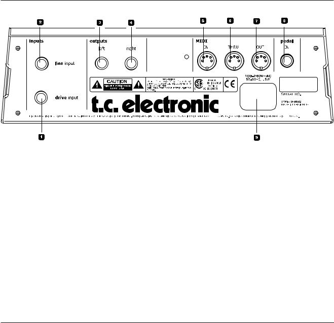
REAR PANEL VIEW
1 - Drive Input
Input for guitar. Use this input to utilize the programmable analog drive section of NOVA System.
Connection type: 1/4” jack.
2 - Line Input
In case you want to use the NOVA System in an effects loop of an amp, the “Effects Loop Send” should be connected to the NOVA System Line In. Then the NOVA System pre-amp section is bypassed and you use the preamp section of your amp for drive.
3/4 - Balanced Outputs
Balanced outputs on 1/4” TRS jack. Use the left output if you do not play in stereo and connect to a single amp.
5 / 6 / 7 - MIDI In / Thru / Out
Standard MIDI interface.
8 - Pedal In
Several types of external pedals can be connected and used to control parameters.
-Connect a G-Switch for preset change and thereby utilize all 8 switches on NOVA System as effects bypass switches.
-Connect an expression control e.g. volume. For perfect response when using an expression
pedal, the pedal must be calibrated. This is done via the pedal menu.
-Via the pedal menu you can set up which parameter the expression pedal should control.
9 - Power In
The switchmode power-supply accepts from 100 to 240 VAC.
9
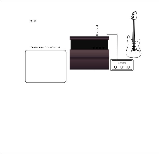
TYPICAL SETUPS
Basic setup
This is a typical basic setup combining NOVA System with one combo amp (or two for stereo) running a clean channel. All effects and overdrive/distortion are generated by NOVA System. A G-Switch (optional) is connected and the NOVA System is then automatically in stomp mode. Presets are then recalled using the G- Switch.
Connections
• Connect your guitar to the NOVA System’s Drive input
• Connect Left output to a guitar amp running a clean channel
• Connect the right output to a second guitar amp for stereo (optional)
• Connect G-Switch (optional) to the pedal input pedal input
Basic settings
• Set input sensitivity via the Levels menu
With a G-Switch connected:
• Activate/deactivate effect blocks pressing the effects switches
• Change presets using G-Switch
With no G-Switch connected:
• Select the Footswitch parameter in the Utility menu and select Pedal (stomp) or Preset mode
• Select preset - if in preset mode
• Activate/deactivate effect blocks pressing the effects switches
10
TYPICAL SETUPS
NOVA System in an effects loop
In this setup we use the preamp section of your combo amp to generate the drive. We use the Line input on the NOVA System and thereby bypass the NOVA Systems drive section. An expression pedal is connected to pedal in for real-time control of e.g. volume.
Connections
• Connect guitar to the input of the combo amp.
• Connect the effects loop “send” of the amp to NOVA Systems Line input.
• Connect left output to the effects loop return (=power amp in) of your amp. For a stereo setup connect the NOVA System right output to the effects loop return (power amp in) of the other amp.
• Connect an expression pedal to the NOVA System Pedal in.
Basic settings
• Set input sensitivity via the Levels menu according to the highest pedal level
• Select the Footswitch parameter in the Utility menu and select Pedal (stomp) or Preset mode
• Select preset (if in preset mode)
• Activate/deactivate effect blocks pressing the effects switches.
• Calibrate the expression pedal via the pedals menu
• Assign parameters to the expression pedal via the Pedal menu
11
MENU - ROUTING
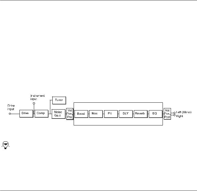
Routing
NOVA System has three ways of routing the chain of effects: Serial, Semi Parallel and Parallel.
Basics
• Press MENU
• Select Routing using encoder D
• Press MENU to confirm
• Set values using encoders A, B and C
• Change pages using encoder D
• Confirm by pressing MENU
• Exit by pressing MENU again
Serial
The Serial routing connects all effect blocks “in a straight line”. This means that each effect block affects the following effect(s).
If a delay with a long delay time is used in combination with a reverb, you may find the added reverb on the delay 


 repeats disturbing. In that case, use either the Semi Parallel or Parallel routing.
12
MENU - ROUTING
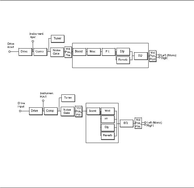
Semi Parallel
The Semi Parallel routing connects most effect blocks serially, but the reverb and delay blocks are now connected in parallel. Consequently, the delay and reverb effects do not affect each other. This means that no reverb is added to the delay repeats.
Parallel
In the Parallel routing, the same signal is fed to the input of the modulation, delay and reverb sections, and therefore these effects will not affect each other.
13
MENU - LEVELS
Levels menu
Basics
• Press LEVELS to access
• Set values using encoders A, B and C
• Change pages using encoder D
Where nothing else is stated the range of the level parameters is -100 dB to 0 dB.
Volume
Range: -100 dB to 0 dB
Level control that can be positioned either pre or post effects processing. The position of the volume control is set by the Position parameter (see also routing schematic).
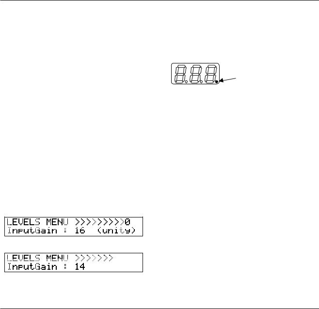
Input Gain
Range: 0 dB to 24 dB
Guitars have different output levels. So has pedals you may have placed before the NOVA System. This is how you set the correct gain.
•Switch on any pedal in your signal chain that is placed prior to NOVA System and may boost the signal
•Strum your guitar as hard as you do when you play
•Adjust the line gain until the “0” appears:
•Then back off a few dB:
•The correct gain is now set and you have unity gain through NOVA System.
Clipping indication
If you change the input gain considerably, e.g. by switching to a different guitar or changing levels on a pedal placed before the NOVA System, the input of the NOVA System may be clipping. This is indicated by the small dot in the far rightmost side of the numeric display:
Left Output & Right Output
Range: -100 dB to 0 dB
Individual level control for left and right outputs. These levels can be set per preset.
Input
Range: Drive or Line
Selects the input. Select “Drive” if you have connected your guitar to the Drive input and want to utilize the NOVA Systems Drive effect block.
Select “Line” if you have connected your guitar to the Line input. (see also routing schematic).
Volume Position
The Volume parameter is typically controlled by an expression pedal. If you connect an expression pedal to the pedal input the pedal will control this parameter per default.
The Volume Position parameter defines where the volume is controlled. The options are:
Pre: The volume is controlled right after the Drive section and before the effects. This allows for effects such as Delay and Reverb to “hang”, even if you lower the level using an expression pedal.
Post: The volume is controlled after the effects. This means that the volume of the entire signal, including effects, is controlled.
14
 Loading...