

Page 1

SERVICE
MANUAL
McDonald's IntelliGap Grills
C832/C834/C835/C836/C838/C842/C844/C845
072768-S 4/19/11 (Original Publication)
(Updated 1/25/16)
Page 2

Page 3

Table of Contents
Section 1: Introduction 1...............................................
Safety 2.............................................................
Installation Instructions 4...............................................
Environmental Notices 5...............................................
Model C832 Specifications 6...........................................
Model C834 Specifications 7...........................................
Model C835 Specifications 8...........................................
Model C836 Specifications 9...........................................
Model C838 Specifications 10...........................................
Model C842 Specifications 11...........................................
Model C844 Specifications 12...........................................
Model C845 Specifications 13...........................................
Patty Placement Guides 14.............................................
Section 2: Controls and Systems 17......................................
Control Keys 18........................................................
Control Overview 21....................................................
Control Operation 22...................................................
LonWorks® Gateway 47................................................
Software Loading Procedures 50.........................................
Electrical Power Distribution 52..........................................
Amp Draw 53..........................................................
Pneumatic System 59..................................................
Model C835 & C845 Gas Connections 60.................................
Model C835 & C845 Heating System Operation - Domestic 63...............
Model C845 Heating System Operation - Pimple Pilot 64....................
Model C835 & C845 Ignition Detection Control - Domestic 65................
High Voltage Gas System - IDC Overview 66..............................
C832/C834/C835 (Two Platen Models) Exhaust Hoods 71..................
C842/C844/C845 (Three Platen Models) Exhaust Hoods 72.................
Table of Contents McDonald's Intelligap Grills
Page 4

Table of Contents - Page 2
Section 3: Troubleshooting 73...........................................
General Troubleshooting Guide 74.......................................
Error Messages 81.....................................................
Motor/Platen Troubleshooting 82.........................................
“Probe Open” Troubleshooting Chart 91..................................
“Probe Fail“ Troubleshooting Chart 92....................................
“Clam Still Latched” Troubleshooting Chart 93.............................
“Clam Did Not Latch” Troubleshooting Chart 94............................
Meat Quality Troubleshooting 95.........................................
Section 4: Parts 97......................................................
Warranty Explanation 98................................................
C832 Exploded View 100................................................
C834 Exploded View 102................................................
C835 Exploded View 104................................................
C836 Exploded View 106................................................
C838 Exploded View 108................................................
C842 Exploded View 110................................................
C844 Exploded View 112................................................
C845 Exploded View 114................................................
Control A.-Box - X72514-12 (C832 - 60 Hz) 116.............................
Control A.-Box - X72514-40 (C832 - 50 Hz) 118.............................
Control A.-Box - X73133-12 (C835 - 60 Hz) 120.............................
Control A.-Box - X73133-40 (C835 - 50 Hz) 122.............................
Control A.-Box - X83099-27 (C836 & C838) 124............................
Control A.-LON - X83096-26 (C836 & C838, SN M5057035 & Prior) 125.......
Control A.-Lower - X72707-23 (60 Hz) -75 (50 Hz) (C842/C844) 126..........
McDonald's Intelligap Grills Table of Contents
Page 5

Table of Contents - Page 3
Control A.-Lower - X73383-23 (60 Hz) -75 (50 Hz) (C845) 127................
Control A.-Upper - X72827-12 (C842 - 60 Hz) 128...........................
Control A.-Upper - X72889-40 (C842/C844 - 50 Hz) 129.....................
Control A.-Upper - X73384-12 (C845 - 60 Hz) 130...........................
Control A.-Upper - X73696-40 (C845 - 50 Hz) 132...........................
Control A.- Switch - X79377-SER / X79377-INT (C832/C834/C835) 134........
Control A.-Switch - X83527-INT (C836 & C838) 135.........................
Control A.-Switch - X72433 / X72433-INT (C842/C844) 136..................
Control A.- Switch - X73393 (C845) 137....................................
Transformer A. - X73649 (60 Hz) -26 (50 Hz) (C845) 138....................
Platen A.-Ser - X73333-23 (60 Hz) -75 (50 Hz) (C832/C834/C835/C836/C838) . . .
139
Platen A.-Serv - X73182-23 / -21 (C842/C844/C845 ) 141....................
Platen A.-2450W 230V Serv - X73183-75 (C842/C844/C845) 143.............
Platen A.-Serv WA - X73598-23 / -21 (C842) 145...........................
Platen A.-Serv WA - X73599-75 (C842) 147................................
Springs (C832/C834/C835/C836/C838) 149................................
Springs (C842/C844/C845) 150...........................................
Motor A.-Mount - X73115 (C832/C834/C835/C836/C838) 151................
Motor A.-Mount - X72403 (C842/C844/C845) 152...........................
Manifold Assembly - 073129 (C832/C834/C835) 153........................
Manifold Assembly - 083762 (C836 & C838) 154............................
Manifold Assembly - 072695 (C842/C844/C845) 155........................
Manifold Assembly - X79373-02 (C835) 156................................
Manifold Assembly - X78891-40 (C835 High Voltage) 157....................
Manifold Assembly - X73109-02 (C845) 158................................
Manifold Assembly - X73695-03 (C845 High Voltage) 159....................
Table of Contents McDonald's Intelligap Grills
Page 6

Table of Contents - Page 4
Compressor A.-Air - X73128-12 (60 Hz) -27 (50 Hz) (C832) 160..............
Compressor A.-Air - X73288-27 (C834) 161................................
Compressor A.-Air - X73143- (C835) 162..................................
Compressor A.-Air - X83304-34 (C836 & C838) 163.........................
Compressor A.-Air - X72724-12 (60 Hz) -27 (50 Hz) (C842/C844) 164.........
Compressor A.-Air - X73108-12 (60 Hz) -27 (50 Hz) (C845) 165..............
Accessories (C832/C834/C835/C836/C838) 166............................
Accessories (C842/C844/C845) 167.......................................
Parts List 168...........................................................
Wiring Diagrams 200....................................................
CAUTION: Information in this manual is intended to be used by Taylor Authorized
Service Technicians only.
Note: Only instructions originating from the factory or its authorized translation
representative(s) are considered to be the original set of instructions.
Note: Continuing research results in steady improvements; therefore, information
in this manual is subject to change without notice.
E 2011 Carrier Commercial Refrigeration, Inc. (Original Publication)
(Updated January, 2016)
072768-S
Any unauthorized reproduction, disclosure, or distribution of copies by any person of any portion of this
work may be a violation of Copyright Law of the United States of America and other countries, could result
in the awarding of Statutory Damages of up to $250,000 (17 USC 504) for infringement, and may result
in further civil and criminal penalties.
All rights reserved.
Taylor Company
a division of Carrier Commercial Refrigeration, Inc.
750 N. Blackhawk Blvd.
Rockton, IL 61072
McDonald's Intelligap Grills Table of Contents
Page 7

Section 1: Introduction
S Safety
S Installation Instructions
S Specifications
S Environmental Notices
S Patty Placement Guides
McDonald's Intelligap Grills
1
Introduction
Page 8
Safety
We, at Taylor Company, are deeply committed to
manufacturing safe operating and serviceable
equipment. The many built-in safety features that
are part of all Taylor equipment are aimed at
protecting operators and trained service technicians
alike.
This manual is intended exclusively for
Taylor Company authorized service personnel.
DO NOT operate the grill before reading
the Operator's Manual. Failure to follow this
instruction may result in equipment damage, poor
grill performance, health hazards, or personal injury.
In all areas of the world, equipment should
be installed in accordance with existing local codes.
Please contact your local authorities if you have any
questions.
Care should be taken to ensure that all basic safety
practices are followed during the installation and
servicing activities related to the installation and
service of Taylor equipment.
S Only authorized Taylor service personnel
should perform installation and repairs on
the equipment.
S Authorized service personnel should consult
OSHA Standard 29CFRI910.147 or the
applicable code of the local area for the
industry standards on lockout/tagout
procedures before beginning any installation
or repairs.
S Authorized service personnel must ensure
that the proper PPE (Personal Protective
Equipment) is available and worn when
required during installation and service.
S Authorized service personnel must remove
all metal jewelry, rings, and watches before
working on electrical equipment.
Take precautions to protect eyes, lungs, and
all parts of the body from potential harm when using
any chemical cleaner. Failure to follow this
instruction may result in a chemical burn. Please
refer to the product MSDS for additional safety
information.
Use extreme caution when installing,
servicing, operating, and cleaning the grill.
S AVOID CONTACT with hot grill surfaces or
hot grease.
S DO NOT prepare or remove product without
proper equipment.
S DO NOT allow untrained personnel to
operate the grill.
S Use extreme caution when cleaning the grill.
Failure to follow these instructions could result in
severe burns from high temperatures.
This equipment must be properly
grounded!
Do not operate this unit unless it is properly
grounded and all service panels and access doors
are restrained with screws. Failure to do so can
result in severe personal injury from electrical shock!
S DO NOT operate the grill with larger fuses
than specified on the data label.
S DO NOT attempt any repairs unless the
power supply to the grill has been
disconnected.
Failure to follow these instructions may result in
severe personal injury from electrical shock.
Introduction
2
McDonald's Intelligap Grills
Page 9

This unit has many sharp edges that can
cause severe injuries.
This unit must NOT be installed in an area
where a water jet or hose can be used.
NEVER use a water jet or hose to rinse or clean the
unit.
Failure to follow these instructions may result in
electrocution, burns from hot steam, or liquid
collecting inside the grill and destroying electrical
components.
This grill must be placed on a level surface.
Failure to comply may result in personal injury or
equipment damage.
S DO NOT store flammable vapors, liquids, or
combustible material in the vicinity of the
grill.
S Appropriate grill clearance must be
maintained.
Failure to comply could result in a fire hazard.
NOISE LEVEL: Airborne noise emission does not
exceed 70 dB(A) when measured at a distance of
1.0 meter from the surface of the machine and at a
height of 1.6 meters from the floor.
McDonald's Intelligap Grills
3
Introduction
Page 10
Installation Instructions
The following are general installation instructions.
For complete installation details, please see the
checkout card.
Site Preparation
Review the area where the unit is to be installed
before uncrating the unit. Make sure all possible
hazards to the user and the equipment have been
addressed.
For Indoor Use Only: This unit is designed to
operate indoors, under normal ambient
temperatures of 70° 75°F (21° 24°C). The unit
has successfully performed in high ambient
temperatures of 104°(40°C) at reduced capacities.
This unit must be installed on a level surface
to avoid the hazard of tipping. Extreme care should
be taken in moving this equipment for any reason.
Two or more people are required to safely move this
unit. Failure to comply may result in personal injury
or equipment damage.
When uncrating the unit, inspect the unit for
damage. Report any damage to your Taylor
Distributor.
This piece of equipment is made in the USA and has
USA sizes of hardware. All metric conversions are
approximate and vary in size.
Electrical Connections
Three dedicated electrical connections are required
for the models C832, C834, C842, and C844 (two 3
phase and one interlock/control single phase). Two
dedicated electrical connections are required for the
models C835, C836, C838, and C845 (one 3 phase
and one interlock/control single phase). Check the
data plate on the grill for voltage, cycle, phase and
electrical specifications. The power connections are
located behind the access line cover on the rear of
the control box under the front staging side of the
grill.
In the United States, this equipment is intended to
be installed in accordance with the National
Electrical Code (NEC), ANSI/NFPA 70-1987. The
purpose of the NEC code is the practical
safeguarding of persons and property from hazards
arising from the use of electricity. This code contains
provisions considered necessary for safety.
Compliance therewith and proper maintenance will
result in an installation essentially free from hazard!
In all other areas of the world, equipment should be
installed in accordance with the existing local codes.
Please contact your local authorities.
The proper wire size and fused circuit should be
selected according to grill data label information.
Incoming power must be connected to the terminals
with black characters on a white background.
This equipment must be properly
grounded!
Do not operate this unit unless it is properly
grounded and all service panels and access doors
are restrained with screws. Failure to do so can
result in severe personal injury from electrical shock!
Introduction
This equipment is provided with a grounding lug
that is to be properly attached to the rear of the frame
by the authorized installer. The installation location is
marked by the equipotential bonding symbol (5021 of
IEC 60417-1) on the removable panel and the frame.
4
McDonald's Intelligap Grills
Page 11
Ventilation and Clearance
Appliances that are permanently connected
to fixed wiring and for which leakage currents may
exceed 10 mA, particularly when disconnected, not
used for long periods, or during initial installation,
shall have protective devices such as a GFI, to
protect against the leakage of current, installed by
the authorized personnel to the local codes.
Stationary appliances which are not
equipped with a power cord and a plug or another
device to disconnect the appliance from the power
source must have an allpole disconnecting device
with a contact gap of at least 3 mm installed in the
external installation.
Supply cords used with this unit shall be
oilresistant, sheathed flexible cable, not lighter than
ordinary polychloroprene or other equivalent
synthetic elastomersheathed cord (Code
designation 60245 IEC 57). They must be installed
with the proper cord anchorage to relieve conductors
from strain, including twisting, at the terminals and
protect the insulation of the conductors from
abrasion.
To ensure proper operation of this appliance, it must
be installed away from all combustible products.
Failure to allow proper clearance and airflow
may cause poor performance, damage to the
machine, or unsafe operating conditions.
After set up, DO NOT store anything on top
of this appliance. Failure to follow this instruction
may result in a fire.
DO NOT store flammable vaporous, liquids,
or combustible material in the vicinity of the grill.
This includes, but is not limited to walls, floors,
partitions, furniture, curtains, and decorations.
Grease Disposal Container
In order to comply with NSF Standard 4
requirements, an appropriate grease disposal
container must be provided. This container is
supplied by the KES, not the Taylor Company.
The main power supply(s) to the grill must
be disconnected prior to performing any repairs.
Failure to follow this instruction may result in
personal injury or death from electrical shock or
hazardous moving parts, as well as poor
performance or damage to the equipment.
Note: Grills require electrical power for operation. In
the event of a power outage, place the unit in the
OFF position.
DO NOT install the grill in an area where a
water jet could be used to clean or rinse the grill.
Failure to follow this instruction may result in serious
electrical shock.
Environmental Notices
______________________________
If the crossed-out wheeled bin symbol is
affixed to this product, it signifies that this product is
compliant with the EU Directive for Waste Electric/
Electronic Goods (WEEE) as well as other similar
legislation in effect after August 13, 2005. Therefore,
it must be collected separately after its use is
completed and cannot be disposed of as unsorted
municipal waste.
The user is responsible for returning the product to
the appropriate collection facility, as specified by
your local codes.
For additional information regarding applicable local
laws, please contact the municipal facility and/or
local distributor.
McDonald's Intelligap Grills
5
Introduction
Page 12
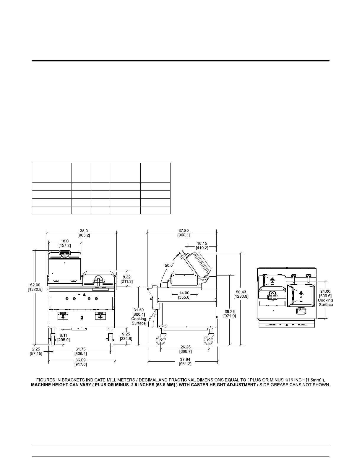
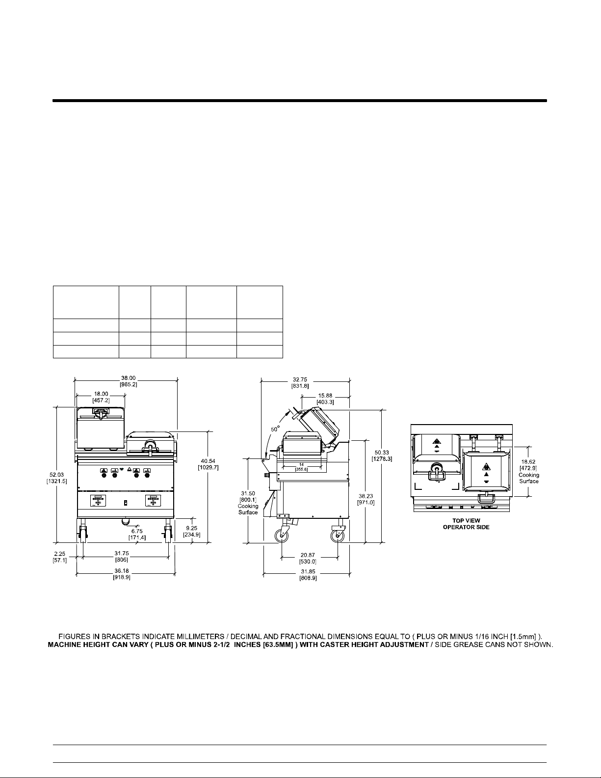
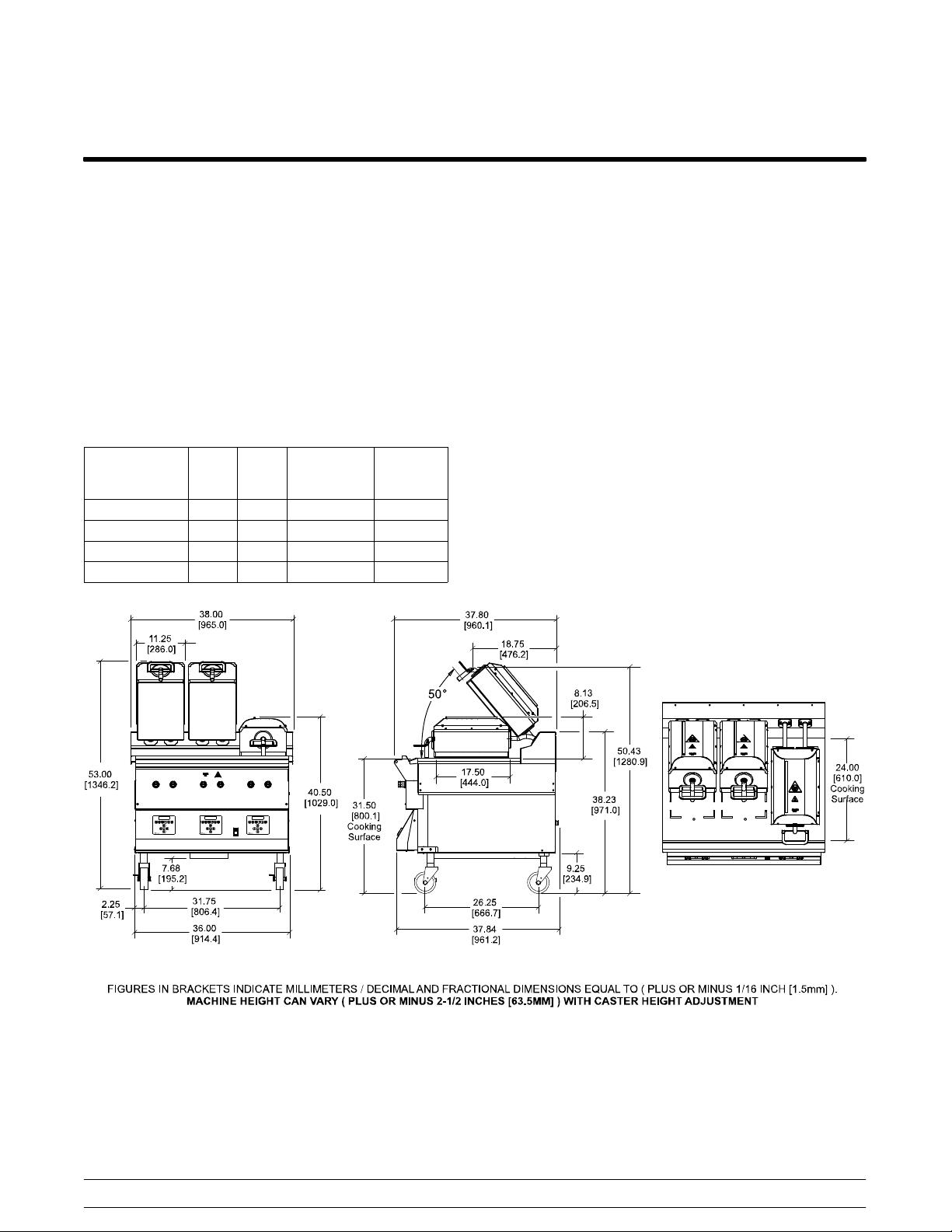
Model C832 Specifications
See the data label for exact specifications.
Electrical
Standard is 208/60/3 phase.
Three dedicated electrical connections are required;
two, three phase and one interlock/control single
phase. See electrical chart for proper electrical
requirements. Manufactured to be permanently
connected. Consult your KES or local Taylor
distributor for cord and receptacle specifications as
local codes allow.
Electrical Total
Amp
208/60/3 56 20 120/60/1 7A
240/60/3 48 20 120/60/1 7A
480/60/3 24 20 120/60/1 7A
400/50/3n~ 29 20 230/50/1 4A
TotalKWInterlock/
Control
Voltage
Interlock
Fuse Size
Dimensions
Width: 38” (965 mm)
Depth: 37-7/8” (962 mm)
Height : 49-1/2 to 54-1/2” (1257 to 1384 mm)
Cooking Surface Height: 29 to 34” (737 to 864 mm)
Floor Clearance: 3-3/4 to 8-3/4” (96 to 223 mm)
(Casters may be adjusted.)
Approximate Weight
Net: 880 lbs. (399.2 kgs.)
Crated: 924 lbs. (419.1 kgs.)
Volume
54 cu. ft. (1.51 cu. m.)
150520
Introduction
Figure 1
6
McDonald's Intelligap Grills
Page 13
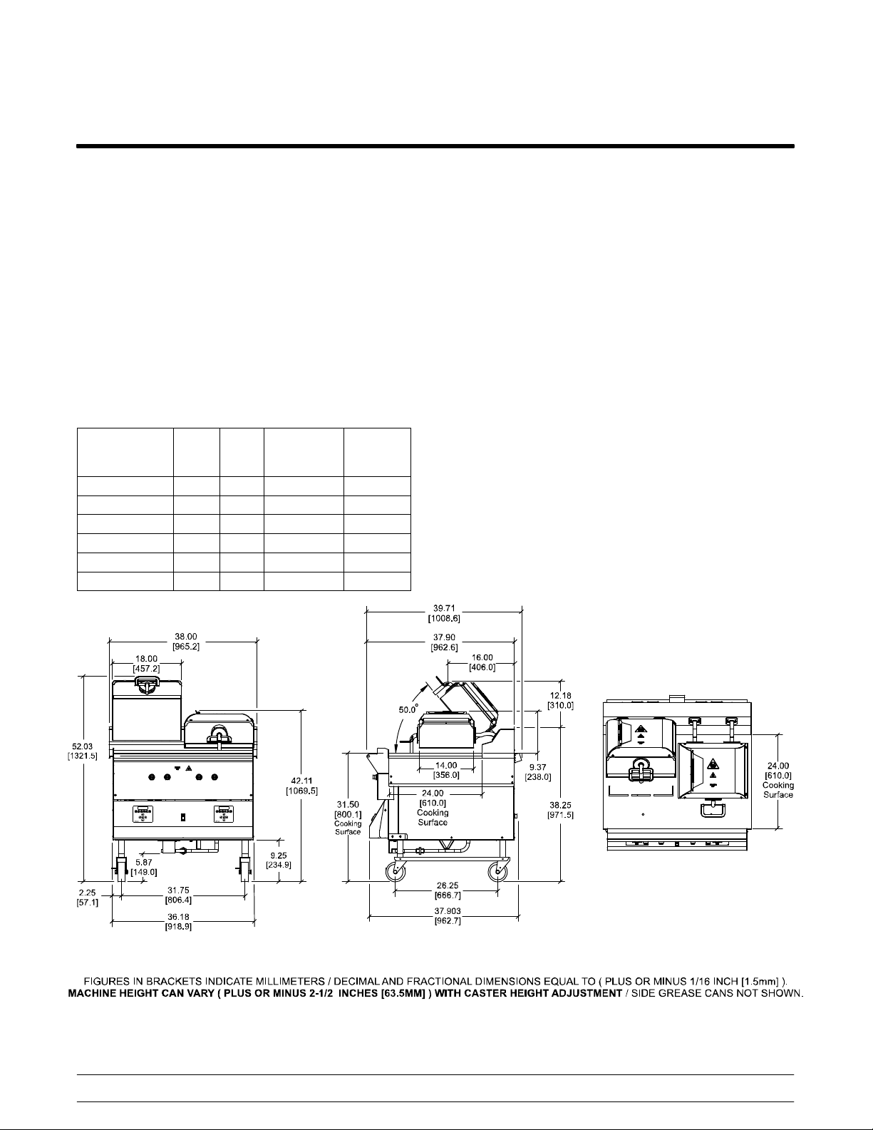
Model C834 Specifications
See the data label for exact specifications.
Electrical
Standard is 400/50/3 phase.
Three dedicated electrical connections are required;
two, three phase and one interlock/control single
phase. See electrical chart for proper electrical
requirements. Manufactured to be permanently
connected. Consult your KES or local Taylor
distributor for cord and receptacle specifications as
local codes allow.
Electrical Total
Amp
208/60/3 56 20 120/60/1 7A
220/380/60/3 31 20 230/60/1 4A
400/50/3n~4w 29 20 230/50/1 4A
TotalKWInterlock/
Control
Voltage
Interlock
Fuse
Size
Dimensions
Width: 38” (965 mm)
Depth: 32-3/4” (832 mm)
Height : 49-9/16 to 54-9/16” (1258 to 1385 mm)
Cooking Surface Height: 29 to 34” (737 to 864 mm)
Floor Clearance: 4-1/4 to 9-1/4” (108 to 235 mm)
Approximate Weight
Net: 758 lbs. (343.8 kgs.)
Crated: 872 lbs. (395.5 kgs.)
Volume
53.7 cu. ft. (1.52 cu. m.)
McDonald's Intelligap Grills
Figure 2
7
150520
Introduction
Page 14
Model C835 Specifications
See the data label for exact specifications.
Electrical
Standard is 208/60/3 phase.
Two dedicated electrical connections are required;
one, three phase and one interlock/control single
phase. See the electrical chart for the proper
electrical requirements. Manufactured to be
permanently connected. Consult your KES or local
Taylor distributor for cord and receptacle
specifications as local codes allow.
Electrical Total
Amp
208/60/3 30 8.4 120/60/1 7A
240/60/3 24 8.4 120/60/1 7A
200/50/60/3 27 8.4 100/60/1 4A
220/380/60/3 14 8.4 220/60/1 4A
220/50/60/3 30 9.0 120/60/1 7A
400/50/3n~ 4w 14 8.4 220/50/1 4A
TotalKWInterlock/
Control
Voltage
Interlock
Fuse
Size
Gas
Two ceramic infrared burners: 30,000 BTUH each.
Manifold pressure: 3.5” w.c. natural, 10.5” w.c.
propane.
Dimensions
Width: 38” (965 mm)
Depth: 39-3/4” (1010 mm)
Height : 49-9/16 to 54-9/16” (1258 to 1385 mm)
Cooking Surface Height: 29 to 34” (737 to 864 mm)
Floor Clearance: 3-3/8 to 8-3/8” (86 to 213 mm)
(Casters may be adjusted.)
Approximate Weight
Net: 861 lbs. (390.5 kgs.)
Crated: 970 lbs. (440.0 kgs.)
Volume
53.7 cu. ft. (1.52 cu. m.)
150520
Introduction
Figure 3
8
McDonald's Intelligap Grills
Page 15
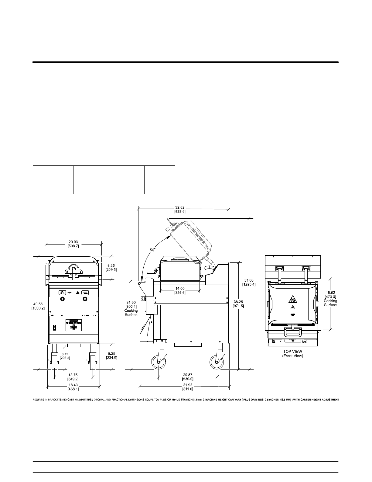
Model C836 Specifications
See the data label for exact specifications.
Electrical
Two dedicated electrical connections are required.
See the electrical chart for the proper electrical
requirements. Manufactured to be permanently
connected. Consult your KES or local Taylor
distributor for cord and receptacle specifications as
local codes allow.
Electrical Total
Amp
400/50/3n~ 16 8.8 230/50/1 4A
TotalKWInterlock/
Control
Voltage
Interlock
Fuse Size
Dimensions
Width: 20” (508 mm)
Depth: 32-5/8” (829 mm)
Height : 48-1/2” to 53-1/2” (1232 to 1359 mm)
Cooking Surface Height: 29 to 34” (737 to 864 mm)
Floor Clearance: 5-5/8 to 10-5/8” (143 to 270 mm)
(Casters may be adjusted.)
Approximate Weight
Net: 386 lbs. (173.7 kgs.)
Crated: 466 lbs. (209.7 kgs.)
Volume
33.1 cu. ft. (0.9 cu. m.)
McDonald's Intelligap Grills
Figure 4
9
150520
Introduction
Page 16
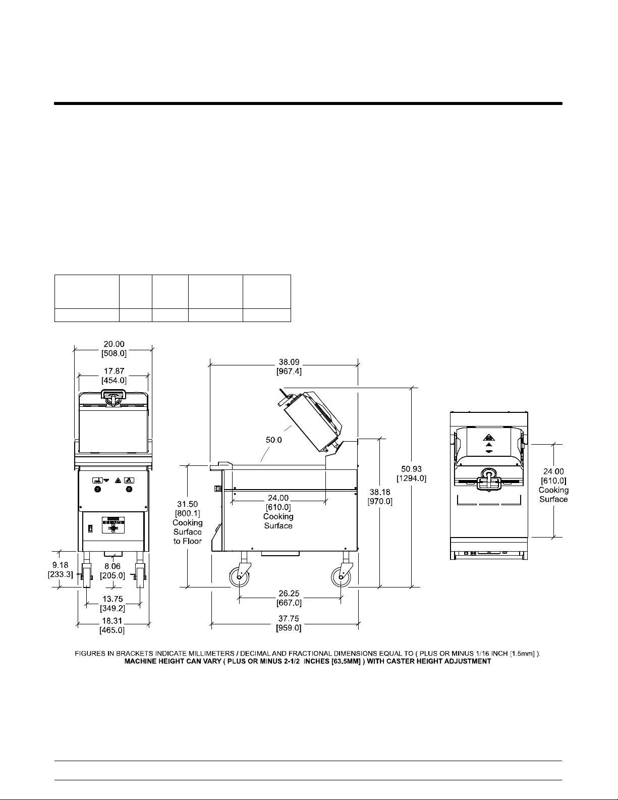
Model C838 Specifications
See the data label for exact specifications.
Electrical
Two dedicated electrical connections are required.
See the electrical chart for the proper electrical
requirements. Manufactured to be permanently
connected. Consult your KES or local Taylor
distributor for cord and receptacle specifications as
local codes allow.
Electrical Total
Amp
400/50/3n~ 18 9.3 230/50/1 4A
TotalKWInterlock/
Control
Voltage
Interlock
Fuse
Size
Dimensions
Width: 20” (508 mm)
Depth: 38” (965 mm)
Height : 48-1/2” to 53-1/2” (1232 to 1359 mm)
Cooking Surface Height: 29 to 34” (737 to 864 mm)
Floor Clearance: 5-5/8 to 10-5/8” (143 to 270 mm)
(Casters may be adjusted.)
Approximate Weight
Net: 487 lbs. (219.2 kgs.)
Crated: 567 lbs. (255.2 kgs.)
Volume
33.1 cu. ft. (0.9 cu. m.)
150520
Introduction
Figure 5
10
McDonald's Intelligap Grills
Page 17
Model C842 Specifications
See the data label for exact specifications.
Electrical
Standard is 208/60/3 phase.
Three dedicated electrical connections are required;
two, three phase and one interlock/control single
phase. See electrical chart for proper electrical
requirements. Manufactured to be permanently
connected. Consult your KES or local Taylor
distributor for cord and receptacle specifications as
local codes allow.
Electrical Total
Amp
208/60/3 69 25 120/60/1 10A
220/50/60/3 66 25 220/50/60/1 10A
220/380/60/3 38 25 220/60/1 10A
400/50/3n~4w 32 22 230/50/1 10A
TotalKWInterlock/
Control
Voltage
Interlock
Fuse
Size
Dimensions
Depth: 38” (965 mm)
Width: 37-7/8” (962 mm)
Height : 50-1/2 to 55-1/2” (1283 to 1410 mm)
Cooking Surface Height: 29 to 34” (737 to 864 mm)
Floor Clearance: 5-3/16 to 10-3/16”
(132 to 259 mm) (Casters may be adjusted.)
Approximate Weight
Net: 940 lbs. (426.4 kgs.)
Crated: 990 lbs. (449.1 kgs.)
Volume
54 cu. ft. (1.51 cu. m.)
McDonald's Intelligap Grills
Figure 6
11
150520
Introduction
Page 18
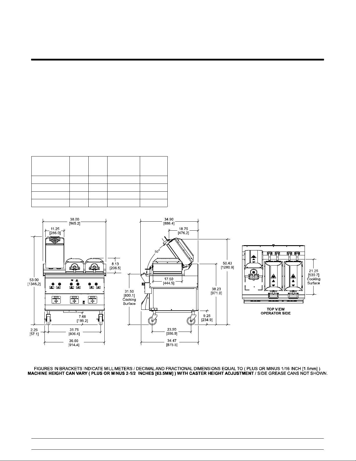
Model C844 Specifications
See the data label for exact specifications.
Electrical
Three dedicated electrical connections are required;
two, three phase and one interlock/control single
phase. See electrical chart for proper electrical
requirements. Manufactured to be permanently
connected. Consult your KES or local Taylor
distributor for cord and receptacle specifications as
local codes allow.
Electrical Total
Amp
208/60/3 63 22.5 120/60/1 7A
220/380/60/3 38 24.9 220/60/1 4A
400/50/3n~ 32 22.0 230/50/1 4A
220/50/60/3 64 24.2 220/50/60/1 7A
TotalKWInterlock/
Control
Voltage
Interlock
Fuse
Size
Dimensions
Width: 38” (965 mm)
Depth: 34-15/16” (887 mm)
Height : 50-1/2 to 55-1/2” (1283 to 1410 mm)
Cooking Surface Height: 29 to 34” (737 to 864 mm)
Floor Clearance: 5-3/16 to 10-3/16”
(132 to 259 mm) (Casters may be adjusted.)
Approximate Weight
Net: 870 lbs. (394.6 kgs.)
Crated: 945 lbs. (428.6 kgs.)
Volume
53.7 cu. ft. (1.52 cu. m.)
150520
Introduction
Figure 7
12
McDonald's Intelligap Grills
Page 19
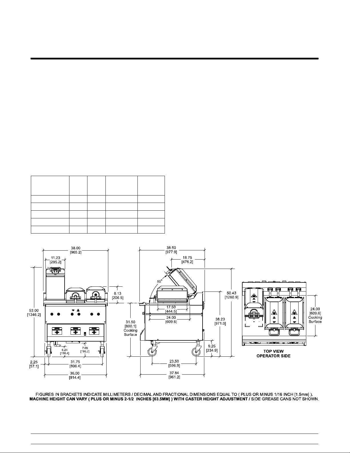
Model C845 Specifications
See the data label for exact specifications.
Electrical
Standard is 208/60/3 phase.
Two dedicated electrical connections are required;
one, three phase and one interlock/control single
phase. See the electrical chart for the proper
electrical requirements. Manufactured to be
permanently connected. Consult your KES or local
Taylor distributor for cord and receptacle
specifications as local codes allow.
Electrical Total
Amp
208/60/3 22 7.8 120/60/1 10A
200/50/60/3 23 7.8 100/50/60/1 10A
220/380/60/3 12 7.8 230/60/1 10A
220/50/60/3 20 7.8 220/60/1 10A
400/50/3n~4w 11 7.8 230/50/1 10A
TotalKWInterlock/
Control
Voltage
Interlock
Fuse
Size
Gas
Three ceramic infrared burners: 25,000 BTUH each.
Manifold pressure: 3.5” w.c. natural, 10.5” w.c.
propane.
Dimensions
Width: 38” (965 mm)
Depth: 38-1/2” (978 mm)
Height : 50-1/2 to 55-1/2” (1283 to 1410 mm)
Cooking Surface Height: 29 to 34” (737 to 864 mm)
Floor Clearance: 3-3/4 to 8-3/4”
(96 to 223 mm) (Casters may be adjusted.)
Approximate Weight
Net: 923 lbs. (418.7 kgs.)
Crated: 1032 lbs. (468.1 kgs.)
Volume
52.6 cu. ft. (1.49 cu. m.)
McDonald's Intelligap Grills
Figure 8
13
150520
Introduction
Page 20

Patty Placement Guides
Placement procedures of meat products must be
followed on the clamshell grill. Meat must be placed
on the lower grill plate two patties at a time, front to
back and right to left. When the cook cycle is
complete, the upper platen will raise.
Note: It is very important that all patties be
removed from the lower grill plate in the same
sequence that they were placed before cooking.
Patties must be removed immediately after the
upper platen has been raised to the OPEN position
and after the meat has been seasoned.
The sandblasted outlines on the lower cook surface
show where product should be placed.
The following charts are to be used as patty
placement guides:
Introduction
14
McDonald's Intelligap Grills
Page 21
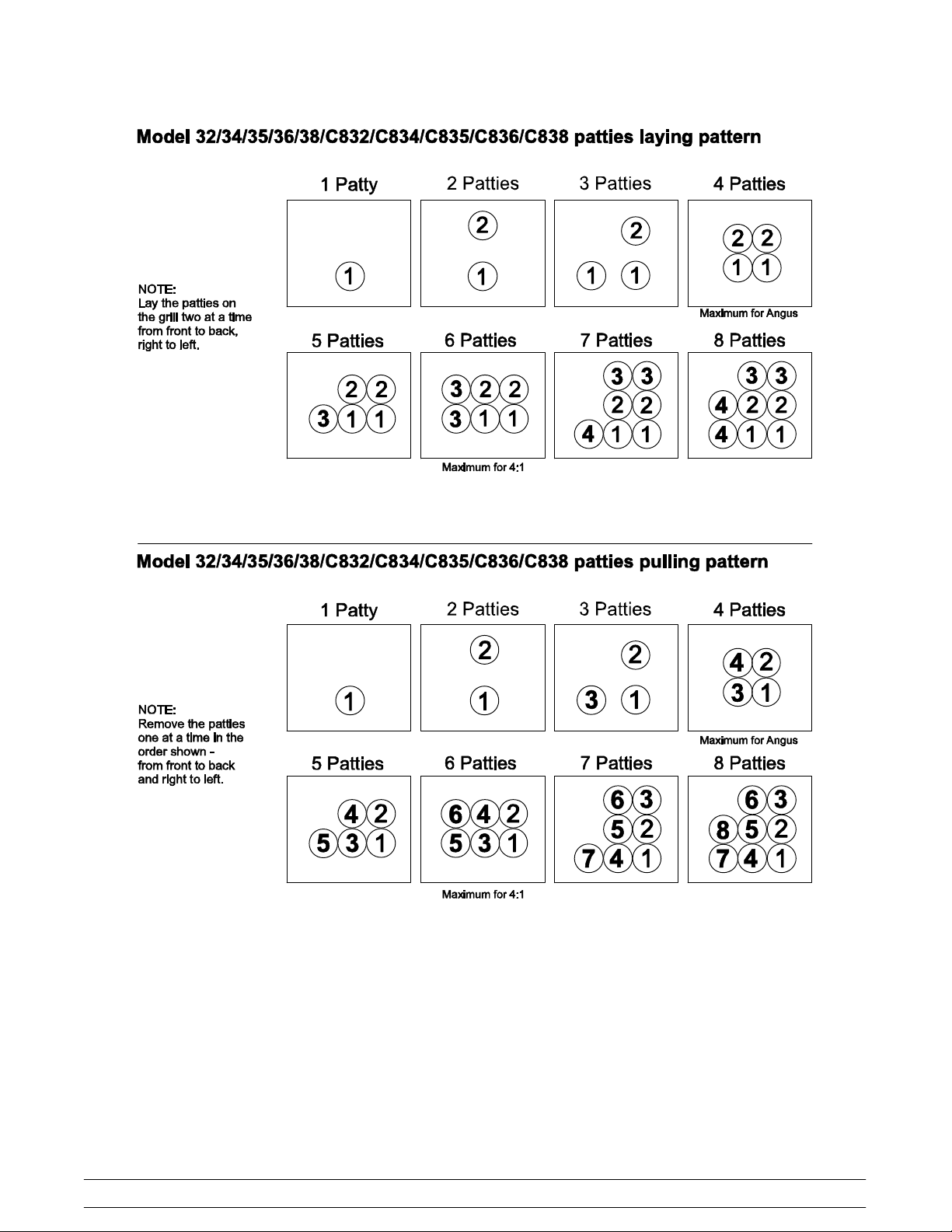
Figure 9
Patty placement procedures for International Markets may differ. Follow the recommendations of your local
McDonald's authorities.
150210
McDonald's Intelligap Grills
15
Introduction
Page 22
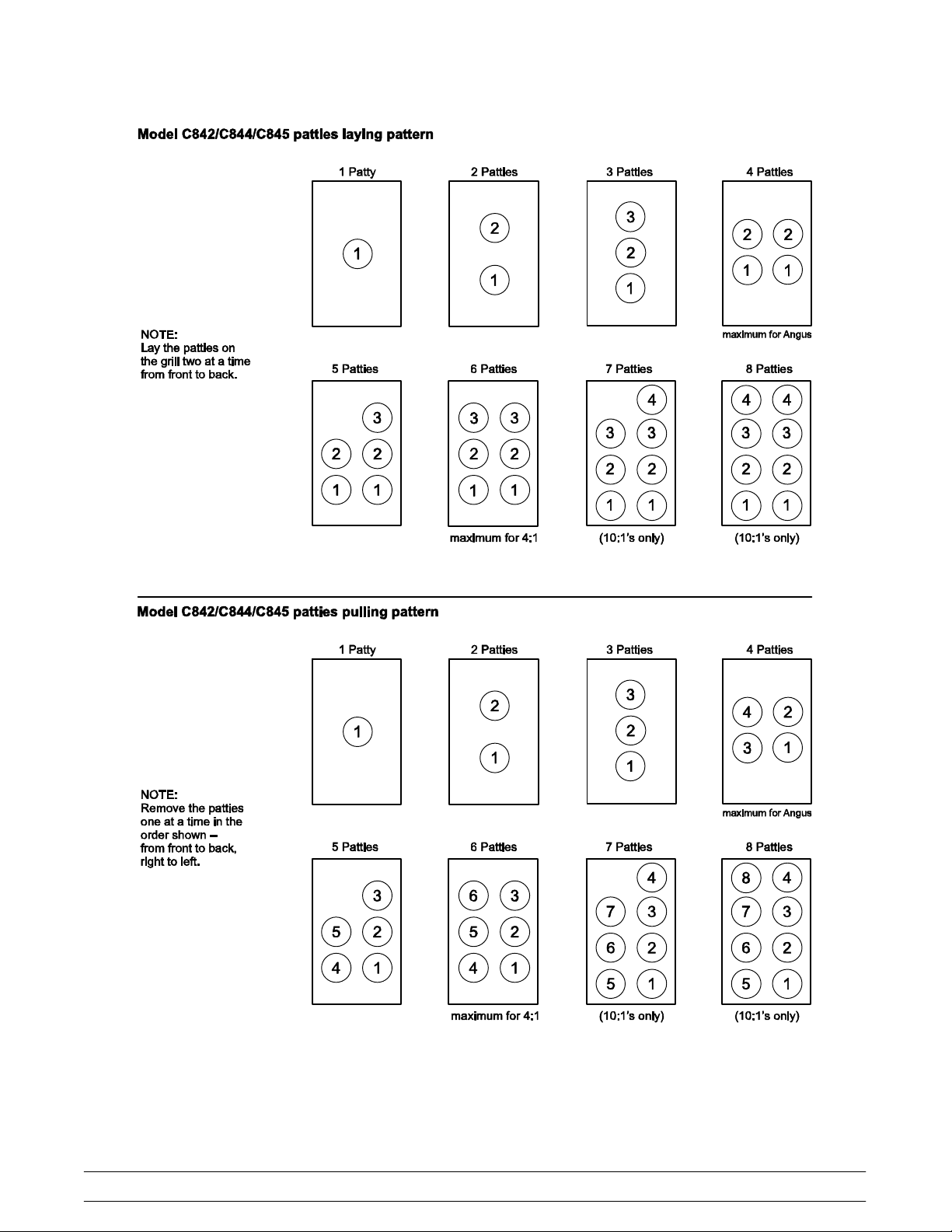
Figure 10
Patty placement procedures for International Markets may differ. Follow the recommendations of your local
McDonald's authorities.
Introduction
16
McDonald's Intelligap Grills
Page 23

Section 2: Controls and Systems
S Control Keys
S Control Overview
S Control Operation
S LonWorks® Gateway
S Software Loading Procedures
S Electrical Power Distribution
S Amp Draw
S Pneumatic System
S Model C835 & C845 Gas Connections
McDonald's Intelligap Grills
S Model C835 & C845 Heating System Operation
S Model C835 & C845 Ignition Detection Control
S High Voltage Gas System - IDC Overview
S Exhaust Hoods
17
Controls and Systems
Page 24
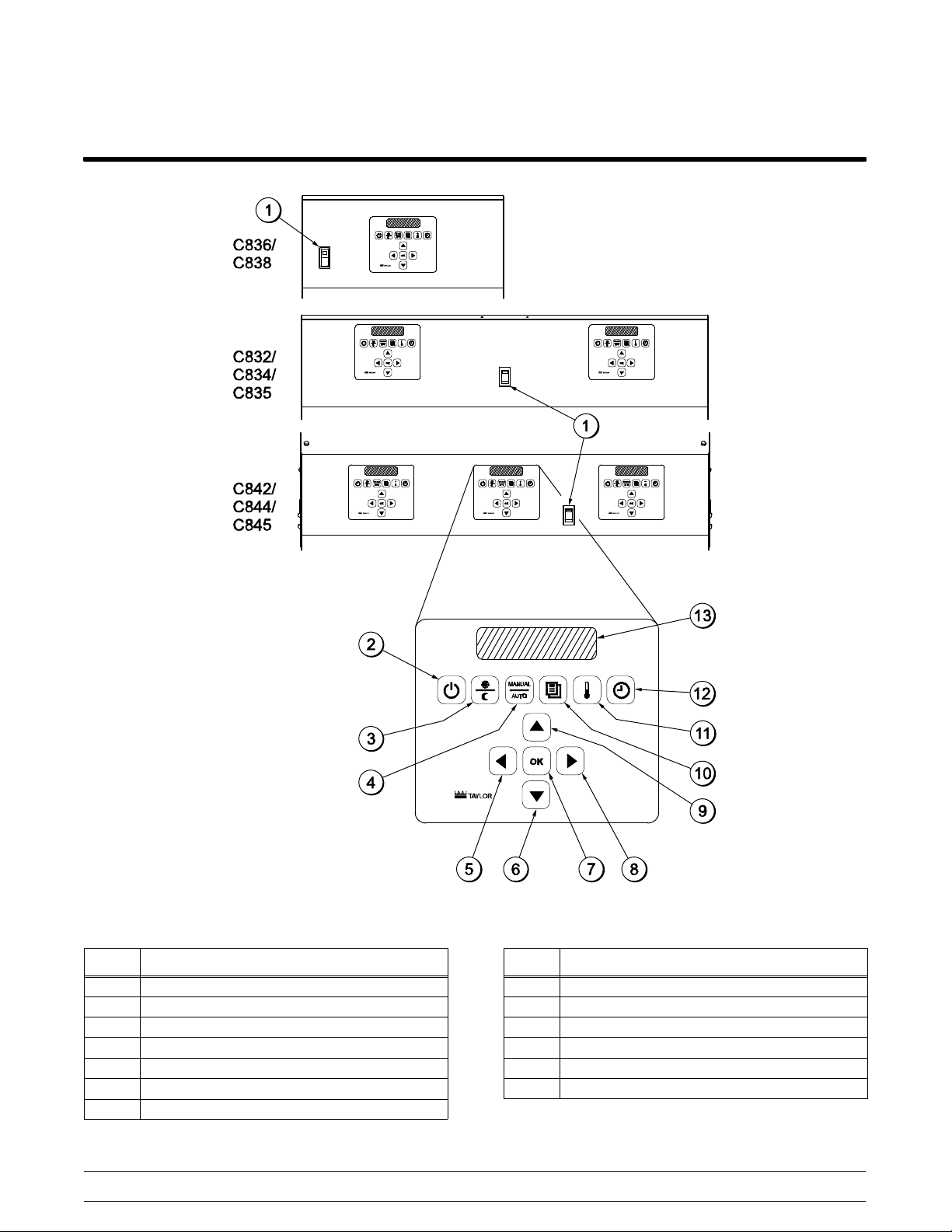
Control Keys
ITEM DESCRIPTION
1 FAN INTERLOCK SWITCH
2 ON/OFF KEY
3 AM/PM KEY
4 MANUAL/AUTO KEY
5 LEFT ARROW KEY
6 DOWN ARROW KEY
7 OK KEY
140922
Controls and Systems
Figure 11
18
ITEM DESCRIPTION
8 RIGHT ARROW KEY
9 UP ARROW KEY
10 PROGRAM KEY
11 TEMPERATURE KEY
12 COOK TIME KEY
13 LIQUID CRYSTAL DISPLAY
McDonald's Intelligap Grills
Page 25
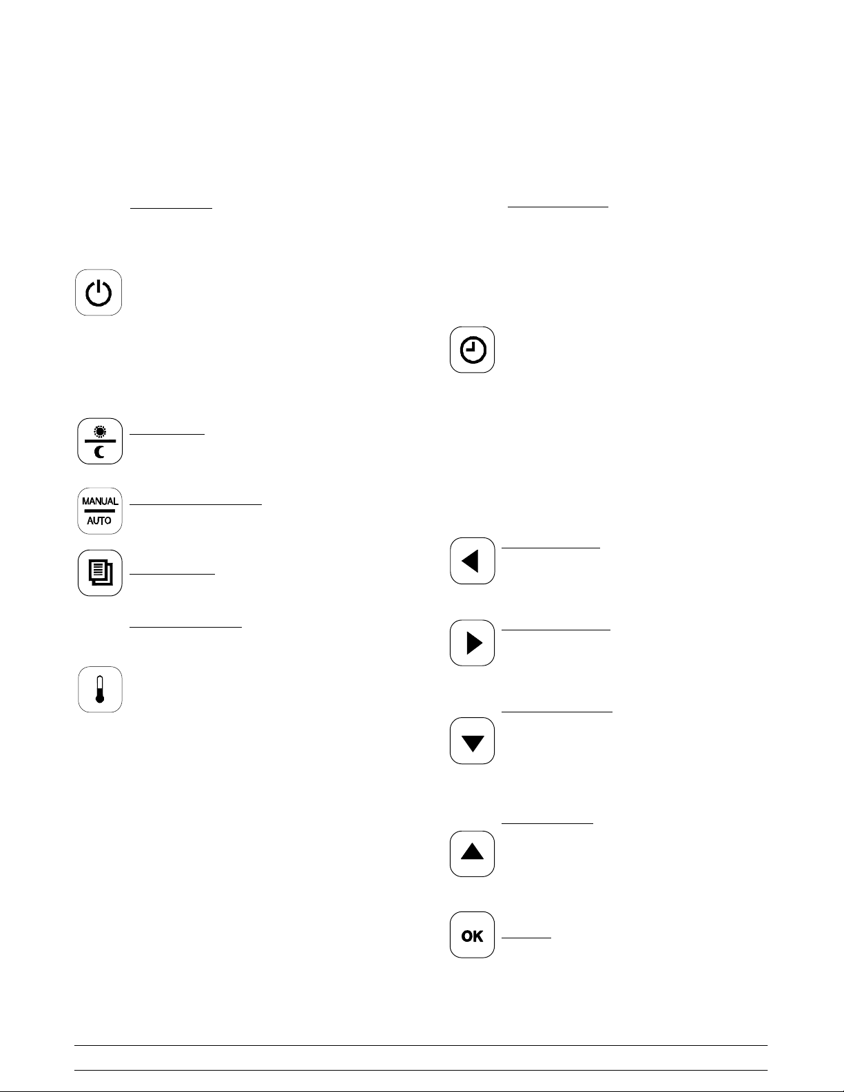
Key Functions
To better communicate in the International arena, the words on many of our operator keys have been replaced by
symbols to indicate their functions. The following keys are used on units built after 2011.
ON/OFF Key
Primary Function: Turns controller on
and off to start a preheating mode and to
auto-gap the platen. It requires a 3-second
continuous press to activate, preventing
unintended operation.
Secondary Function 1: Creates blank
spaces and removes un-used letters in the
“ADD MENU” programming process.
Secondary Function 2: In Programming
mode, moves cursor to next numerical
digit (hundreds, tens, ones).
AM/PM Key
Toggles back and forth between the AM
and PM menu item lists.
MANUAL/AUTO Key
Toggles back and forth between the
Manual and Auto modes.
Program Key
Enters and exits Programming mode.
Cook Time Key (Inactive in Auto mode)
Primary Function: Used in Programming
mode to change “Remove Time” of a
specific menu item.
Secondary Function 1: Press and hold 5
seconds to directly enter Programming
“COOK TIME” in Service Menu.
Advantages:
1. Minimizes key strokes.
2. Speeds up cook time adjustment.
Secondary Function 2: Press and hold 5
seconds when in “ADD ITEM” program.
Scroll to “REMOVE IN” screen. Resets the
“ADD ITEM” Programming back to factory
defaults.
Advantage:
1. Allows correction of programming
errors.
Left Arrow Key
Used in Programming mode to scroll
through menu items. (Inactive in Auto
mode)
Temperature Key
Primary Function: Displays the
temperature of each zone.
Secondary Function: Press and hold for
5 seconds to enter Programming mode
“CALIBRATION” screen in Service Menu.
Advantages:
1. Minimizes key strokes.
2. Speeds up “CAL” process.
Right Arrow Key
Used in Programming mode to scroll
through menu items. (Inactive in Auto
mode)
Down Arrow Key
Used in Programming mode to decrease a
numerical value and to scroll through the
letters of the alphabet and numbers when
entering a new menu item or modifying an
old one. (Inactive in Auto mode)
Up Arrow Key
Used in Programming mode to increase a
numerical value and to scroll through the
letters of the alphabet and numbers when
entering a new menu item or modifying an
old one. (Inactive in Auto mode)
OK Key
Accepts the information entered.
McDonald's Intelligap Grills
19
140922
Controls and Systems
Page 26
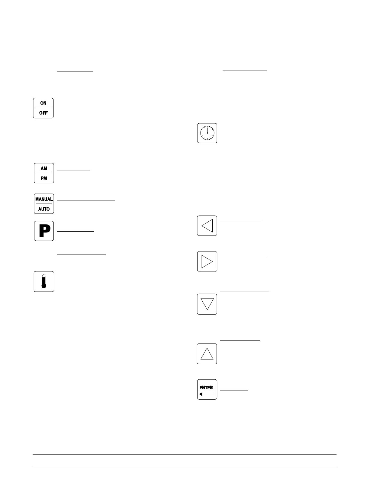
The following keys were used on units built before 2011.
ON/OFF Key
Primary Function: Turns controller on
and off to start a preheating mode and to
auto-gap the platen. It requires a 3-second
continuous press to activate, preventing
unintended operation.
Secondary Function 1: Creates blank
spaces and removes un-used letters in the
“ADD MENU” programming process.
Secondary Function 2: In Programming
mode, moves cursor to next numerical
digit (hundreds, tens, ones).
AM/PM Key
Toggles back and forth between the AM
and PM menu item lists.
MANUAL/AUTO Key
Toggles back and forth between the
Manual and Auto modes.
Program Key
Enters and exits Programming mode.
Cook Time Key (Inactive in Auto mode)
Primary Function: Used in Programming
mode to change “Remove Time” of a
specific menu item.
Secondary Function 1: Press and hold 5
seconds to directly enter Programming
“COOK TIME” in Service Menu.
Advantages:
1. Minimizes key strokes.
2. Speeds up cook time adjustment.
Secondary Function 2: Press and hold 5
seconds when in “ADD ITEM” program.
Scroll to “REMOVE IN” screen. Resets the
“ADD ITEM” Programming back to factory
defaults.
Advantage:
1. Allows correction of programming
errors.
Left Arrow Key
Used in Programming mode to scroll
through menu items. (Inactive in Auto
mode)
Temperature Key
Primary Function: Displays the
temperature of each zone.
Secondary Function: Press and hold for
5 seconds to enter Programming mode
“CALIBRATION” screen in Service Menu.
Advantages:
1. Minimizes key strokes.
2. Speeds up “CAL” process.
Right Arrow Key
Used in Programming mode to scroll
through menu items. (Inactive in Auto
mode)
Down Arrow Key
Used in Programming mode to decrease a
numerical value and to scroll through the
letters of the alphabet and numbers when
entering a new menu item or modifying an
old one. (Inactive in Auto mode)
Up Arrow Key
Used in Programming mode to increase a
numerical value and to scroll through the
letters of the alphabet and numbers when
entering a new menu item or modifying an
old one. (Inactive in Auto mode)
Enter Key
Accepts the information entered.
140922
Controls and Systems
20
McDonald's Intelligap Grills
Page 27
Control Overview
McDonald's Intelligap Grills
Figure 12
21
Controls and Systems
Page 28
Control Operation
To Cook in the Flat Grill Mode
Step 1
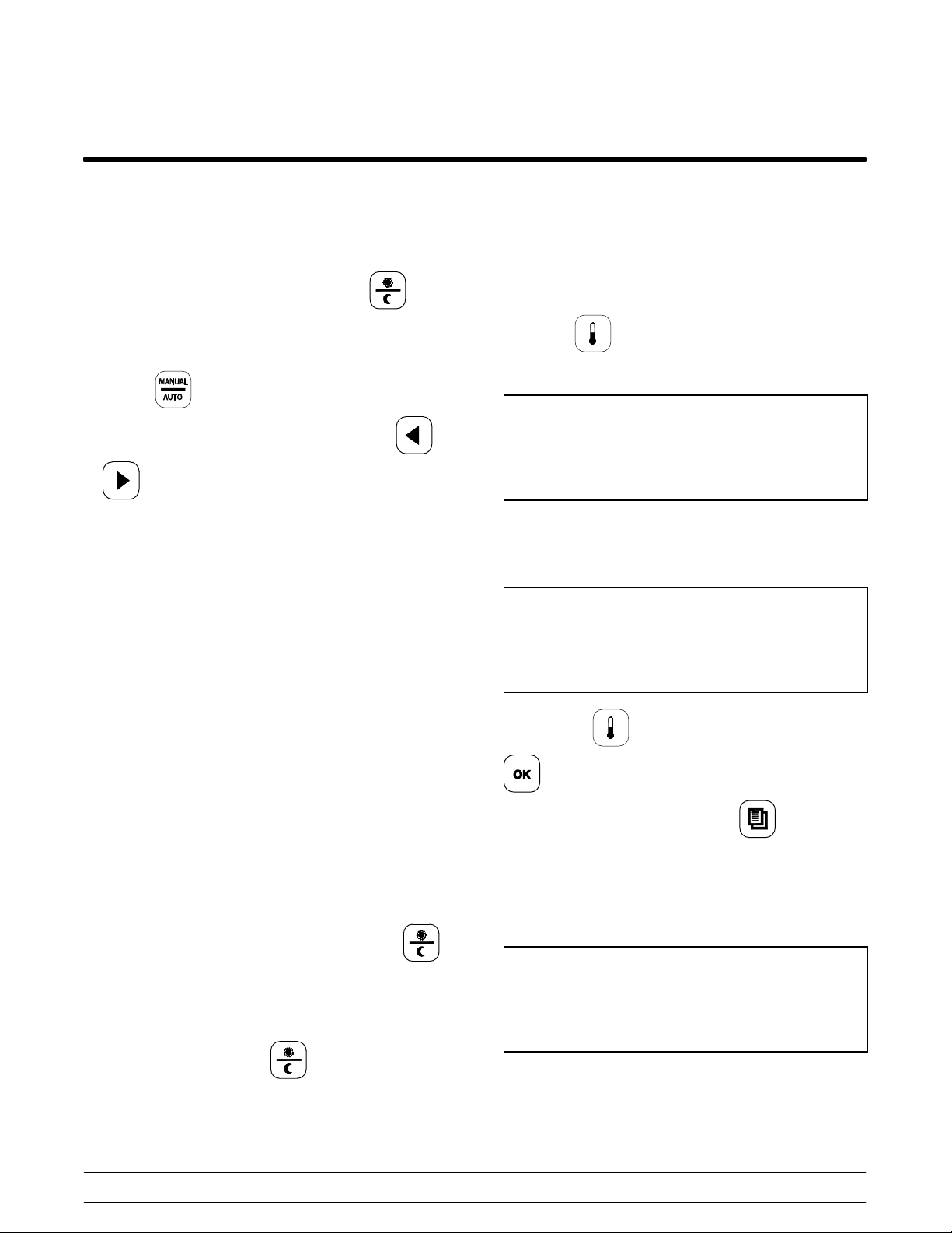
To select a flat grill menu item, press the key
and select “AM” or “PM”.
Step 2
Press the key for the MANUAL Mode. Scroll
to the desired flat menu item by pressing the
or keys. The display may show “TOO COOL”
or “TOO HOT”, until the grill reaches the set
temperatures.
Step 3
After placing product in the prescribed method,
press the STANDBY button to start the cook cycle.
Step 4
Perform the functions that appear on the display
(i.e., sear, turn). Pressing the RAISE button will
cancel the cook cycle.
To Display the Current Temperatures
Note: The actual temperatures may be displayed at
any time, including during a Cook cycle.
Step 1
Press the key. A series of screens will display.
The first screen will display as follows.
Top Bck (AM/PM) Top Frt
Back Cntr Frt
Step 2
The next display will show the actual temperatures.
See the following example.
426 Now/Deg F 425
348 350 349
Step 5
When the cook cycle is complete, the display will
flash the message “REMOVE” and an audible alert
will sound. Remove the product per the prescribed
method.
To Transition From Breakfast to Lunch
Step 1
If the grill is in the AM AUTO Mode, press the
key to select PM.
Step 2
If the grill is set to a certain breakfast item in the
MANUAL Mode, press the key to select PM.
The display may show “TOO COOL” or “TOO HOT”,
until the grill reaches the set temperatures.
Note: If the key is pressed once and the
key is pressed five times, the temperatures
will remain on the screen until the key is
pressed again.
Step 3
The next display will show the set point
temperatures. See the following example.
425 Set/Deg F 425
350 350 350
Step 4
The display will then return to the selected menu
item.
Controls and Systems
22
McDonald's Intelligap Grills
Page 29
Auto Leveling
Step 1
Make sure the grill surfaces are clean and the
release sheets are installed.
Step 2
Allow the grill to reach operating temperature
(minimum of 45 minutes).
Control Menu Access
The Control Menu gives access to all Menu items,
System Set Up items, Software Versions, and
Service Menu items.
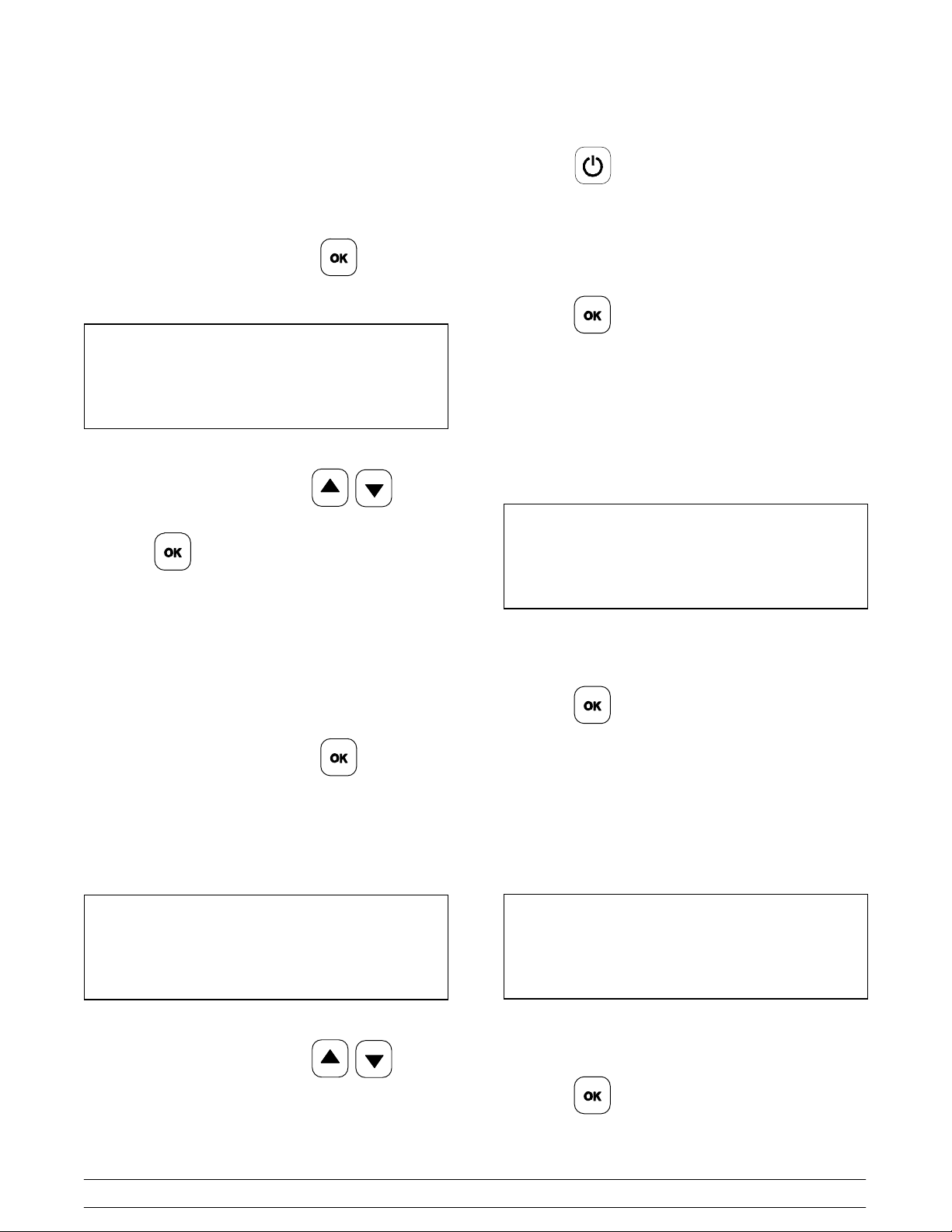
Step 1
Step 3
While the grill is in the MANUAL or AUTO Mode,
press the key twice. The following screen will
be displayed.
PRESS ENTER FOR
AUTO LEVELING
Step 4
Press the key. The following screen appears.
CLOSE GRILL CLAM FOR
AUTO LEVELING
Step 5
Press the STANDBY button. The following screen
appears.
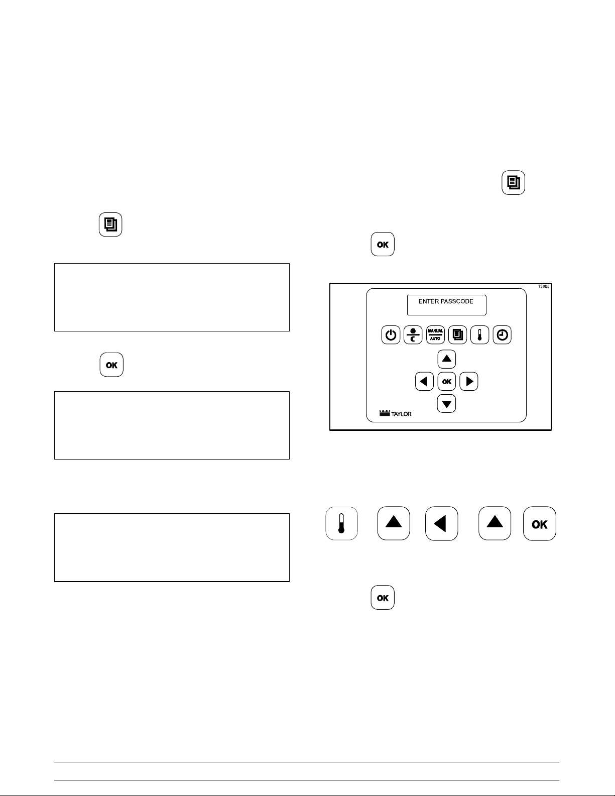
To access the Control Menu, press the key
once to display “PROGRAMMING.”
Step 2
Press the key to display the passcode entry
screen.
Figure 13
Step 3
Enter the Service passcode by pressing the keys in
this order:
PLEASE WAIT FOR
AUTO LEVELING
Step 6
The platen will raise after it has auto-leveled.
McDonald's Intelligap Grills
Step 4
Press the key.
23
Controls and Systems
Page 30
Menu Items
Step 2
After the Service passcode has been entered,
changes to the Menu Items can be made.
IMPORTANT: Changing Numerical Digits in
Menu Items
When making changes to numerical digits, pressing
the keys will increase or decrease digits
in single increments. To change the digits in
increments of 10's and 100's, adjust the first digit
using the keys and then press the
key to move the cursor to the next digit.
Repeat this sequence for each digit until the correct
setting is displayed.
IMPORTANT: Exiting Programming Mode
After making and saving a menu item programming
selection, pressing the OK key exits the
programming mode immediately. If the OK key is not
pressed, the display automatically times-out after
3-5 seconds and exits the programming mode.
To change the setting, press the key
until the desired AM or PM selection is displayed.
Press the key to save the selection.
Remove In
The REMOVE IN feature is used to set an alarm to
activate when the product should be removed from
the grill.
Step 1
After selecting the item, press the key until the
screen displays “REMOVE IN __”.
10:1 - CLAM
REMOVE IN: 044
AM-N PM-Y
This feature is used to select the time of day the
product will be cooked, either in the AM, PM, or
both.
Step 1
After selecting the item, press the key. The
screen will display the item and “AM Y/N PM Y/N.”
10:1 - CLAM
AM N PM Y
Step 2
To change the setting, press the keys
to display the correct setting for the first numerical
digit.
Step 3
Press the key to move the cursor to the next
numerical digit.
Step 4
Repeat this sequence for each numerical digit until
the correct setting is displayed.
Press the key to save the selection.
1141015
Controls and Systems
24
McDonald's Intelligap Grills
Page 31
Remove Alarm
Step 3
This feature is used to determine if the alarm will be
cancelled automatically or manually.
Step 1
After selecting the item, press the key until the
screen displays “REMOVE ALARM”.
10:1 - CLAM
REMOVE ALARM: AUTO
Step 2
To change the setting, press the keys
until the desired setting is displayed.
Press the key to save the changes.
Press the key to move the cursor to the next
numerical digit.
Step 4
Repeat this sequence for each numerical digit until
the correct setting is displayed.
Press the key to save the selection.
Step 5
The Stage 1 Time screen will display. Stage 1 Time
is the amount of time the product will cook during
the first stage of a multi-stage product. (Note: Stage
1 timers are only used for multi-stage product.)
10:1 - CLAM
STAGE 1 TIME: .010
Remove Gap
The REMOVE GAP feature is the finished gap
height of the selected product.
Step 1
After selecting the item, press the key until the
screen displays “REMOVE GAP”.
Gap is measured in 1,000th of an inch. In the
example below, the REMOVE GAP setting is 0.265
inch.
10:1 - CLAM
REMOVE GAP: 265
Step 2
To change the setting, press the keys
to display the correct setting for the first numerical
digit.
Step 6
Repeat Steps 2 - 4 to adjust the time.
Press the key to save the selection.
Step 7
The Stage 1 Gap screen will display. Stage 1 Gap is
the size of the gap that the product will cook during
the first stage of a multi-stage product. (Note: Stage
1 gap is only used for multi-stage product.)
10:1 - CLAM
STAGE 1 GAP: 215
Step 8
Repeat Steps 2 - 4 to adjust the gap.
Press the key to save the selection.
McDonald's Intelligap Grills
25
141020
Controls and Systems
Page 32

Must Remove In
Prep Alarm
This feature activates an alarm to remind the cook to
remove the product from the grill.
Step 1
After selecting the item, press the
key until the
screen displays “MUST REMOVE IN.”
10:1 - CLAM
MUST REMOVE IN: 00
Step 2
To adjust the setting, repeat Steps 2 - 4 from the
Remove Gap section on page 25.
(Note: Factory default is zero.)
Prep Bread In
If enabled, this feature activates an alarm at a set
time before the REMOVE IN time to remind the cook
to toast the buns.
Step 1
After selecting the item, press the key until the
screen displays “PREP BREAD IN.”
If the PREP BREAD IN feature is programmed, this
feature is used to select either MANUAL or AUTO.
Step 1
After selecting the item, press the key until the
screen displays “PREP ALARM.”
10:1 - CLAM
PREP ALARM: AUTO
Step 2
To change the setting, press the keys
until the desired setting is displayed.
Press the key to save the changes.
Top Temp/Bottom Temp
This feature is used to adjust the temperature of the
upper platen and lower grill plate.
Step 1
After selecting the item, press the key until the
screen displays “TOP TEMP”.
10:1 - CLAM
PREP BREAD IN: 000
Step 2
To adjust the setting, repeat Steps 2 - 4 from the
Remove Gap section on page 25.
(Note: Factory default is zero.)
141020
Controls and Systems
10:1 - CLAM
TOP TEMP: 425F
Step 2
To adjust the setting, repeat Steps 2 - 4 from the
Remove Gap section on page 25.
26
McDonald's Intelligap Grills
Page 33

Step 3
The screen will display “BOTTOM TEMP ___”.
10:1 - CLAM
BOTTOM TEMP: 375F
Step 4
To adjust the setting, repeat Steps 2 - 4 from the
Remove Gap section on page 25.
Auto Gap
IMPORTANT! These settings should not be
changed unless authorized by a Taylor Service
Representative. This change should only be
performed to adjust deformed product. Before
attempting to change the product thickness settings,
cook the deformed product in the MANUAL mode.
Step 1
Press the key until the screen displays “AUTO
GAP”. The screen will show two sets of numbers.
The first set of numbers is the minimum gap of the
item. The second set of numbers is the maximum
gap of the item.
10:1 - CLAM
AUTO GAP: 230 TO 330
Auto Selection
This feature is used to determine if the cooking
functions of a product will be automatically selected
or not.
Step 1
After selecting the item, press the key until the
screen displays “AUTO SELECTION”.
Example of a screen:
10:1 - CLAM
AUTO SELECTION: YES
Step 2
Step 2
To adjust the setting for the 1st set of numbers,
repeat Steps 2 - 4 from the Remove Gap section on
page 25.
After the OK key was pressed, the cursor moved to
the 2nd set of numbers. Adjust the second set of
numbers and press the OK key.
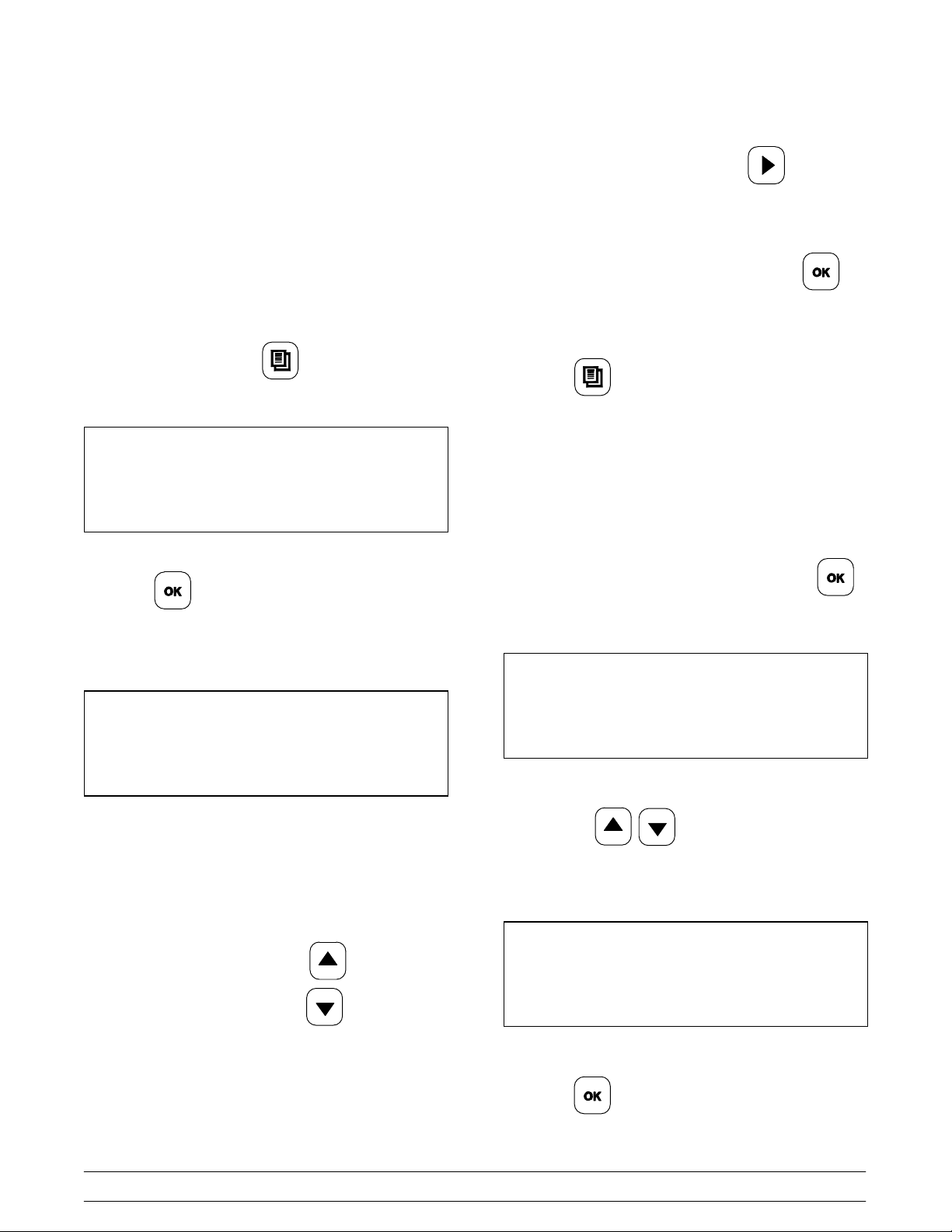
Programming Optional Menu Items
This feature is used to add optional menu items.
Step 1
Access the Control Menu by entering the Service
Menu passcode, per instructions on page 23.
Step 2
Press the key until the screen displays
“MENU ITEMS”.
Step 3
Press the key to scroll to “ADD ITEM”.
To change the selection, press the keys
until the desired selection (YES or NO) is displayed.
Press the key to save the changes.
McDonald's Intelligap Grills
27
ADD ITEM
141020
Controls and Systems
Page 34

Step 4
FLAT SELECTION:
Press the key. The following screen will
display.
M M M M M M M M M M M M
ENTER ITEM NAME
Step 5
Use the keys to change the first default
character into the first desired character.
Step 6
Move cursor to next digit by using the key.
Step 7
Continue entering the appropriate characters until
the complete item name has been entered.
Step 8
If FLAT” was selected, after the key is
pressed, the screen will display “FUNCTIONS: 0”.
The new flat item can have a maximum of three
functions: Turn, Sear, and Turn/Sear.
In the following example, FUNCTION 1: TURN will
be used.
a. Use the key to scroll to the appropriate
number of functions. Press the key. The
screen will display “FUNC1: TURN.”
b. Use the key to scroll to the desired
function. Press the key to accept the
selection.
c. Press the key. The screen will display,
“AM __ PM __”. Use the keys to
scroll to the appropriate selection.
d. Press the key. The screen will display
“TURN IN”. Scroll to the appropriate selection
Press the key until the remaining default
characters are removed. Press the key.
Note: If an error was made while programming the
Optional Menu Item, remove the menu item by
following the “Removing Optional Menu Items”
instructions on page 30.
Step 9
The screen will display, “TYPE: CLAM”.
Press the keys to select “CLAM” or
“FLAT.” Press the key.
141015
Controls and Systems
and press the key.
e. The screen will display TURN ALARM: AUTO”.
Scroll to appropriate selection and press the
key.
f. The screen will display “REMOVE IN”. Scroll to
appropriate selection and press the key.
g. The screen will display “REMOVE ALARM”.
Scroll to the desired selection and press the
key.
h. The screen will display “MUST REMOVE IN.”
Scroll to the desired selection and press the
key.
28
McDonald's Intelligap Grills
Page 35

i. The screen will display “PREP BREAD IN: 000”.
Scroll to the desired selection and press the
e. The screen will display “REMOVE GAP: 000”. If
the new item is a multi-gap product, use the
key.
j. The screen will display “PREP ALARM: AUTO”.
Scroll to the desired selection and press the
key.
k. The screen will display “TOP TEMP OFF.”
Pressing the key will set the TOP TEMP at
150F. To adjust that setting, repeat Steps 2 - 4
from the Remove Gap section on page 25.
l. The screen will display “BOTTOM TEMP OFF.”
Pressing the key will set the TOP TEMP at
150F. To adjust that setting, repeat Steps 2 - 4
from the Remove Gap section on page 25.
For items with multiple functions, repeat these
steps until all the functions have been entered.
CLAM SELECTION:
keys to enter the product gap
specification. Press the key.
f. The screen will display “STAGE1 TIME: 000.”
Scroll to the appropriate time and press the
key.
g. The screen will display, “STAGE1 GAP: 000.”
Scroll to the appropriate gap setting and press
the key.
h. The screen will display “MUST REMOVE IN”.
Scroll to the appropriate selection and press the
key.
i. The screen will display “PREP BREAD IN”. Scroll
to the appropriate selection and press the
key.
If “CLAM” was selected, after the is pressed,
the screen will display “GAP STAGES: 0.”
a. If the new item is a multi-gap product, use the
key to change the gap stage to “1” and
press the key.
b. The screen will display “AM __ PM __”. Use the
keys to select the appropriate option
and press the key.
c. The screen will display “REMOVE IN 000.” Scroll
to the appropriate time and press the key.
d. The screen will display “REMOVE ALARM:
AUTO.” Scroll to appropriate selection and press
j. The screen will display “PREP ALARM: AUTO”.
Scroll to the appropriate selection and press the
key.
k. The screen will display “TOP TEMP OFF.”
Pressing the key will set the TOP TEMP at
150F. To adjust the setting, repeat Steps 2 - 4
from the Remove Gap section on page 25.
l. The screen will then display “BOTTOM TEMP
OFF.” Pressing the key will set the TOP
TEMP at 150F. To adjust the setting, repeat
Steps 2 - 4 from the Remove Gap section on
page 25.
For items with multiple functions, repeat these
steps until all the functions have been entered.
m. The screen will display “AUTO SELECTION:
NO”. Scroll to the appropriate selection and press
the key.
McDonald's Intelligap Grills
29
the key.
141015
Controls and Systems
Page 36

n. The AUTO GAP screen will display. This screen
shows two sets of numbers. The first set of
numbers is the minimum gap and second set of
numbers is the maximum gap of the item.
10:1 - CLAM
AUTO GAP: 230 TO 330
o. Adjust the setting of the 1st set of numbers by
performing Steps 2 - 4 from the Remove Gap
section on page 25. After pressing the OK key,
the cursor moves to the 2nd set of numbers.
Repeat the procedure to adjust the 2nd setting.
p. The screen will display “AM __ PM __”. Use the
Factory Default Settings Reset
Procedures
Perform the following steps to reset the control to
the factory default settings. This feature is available
on software version 2.78 and higher.
Note: Resetting to defaults will default the control to
the 3 platen electric configuration. To reset to a
different configuration (example: 2 platen control),
the setting must be changed in System Set Up.
Step 1
Place the power switch in the ON position and wait
for the control to display “OFF.”
keys to scroll to the appropriate
selection and press the key.
Removing Optional Menu Items
Core menu items cannot be removed. However,
menu items programmed using the “ADD ITEM”
menu option can be removed .
Step 1
Press the key for “MENU ITEMS”.
Step 2
Use the keys to scroll to menu item to
be removed.
Step 3
Press the key until “REMOVE IN” displays.
Step 4
Press and hold the key for 5 seconds, until the
menu item is removed.
Step 2
Press the key once. Then press the following
keys in succession: .
The following screen will display.
PRESS ENTER FOR
MENU ITEMS
Step 3
Press and hold the key for 5 seconds until the
following screen displays.
RESET CORE MENU?
NO
130731
Controls and Systems
30
McDonald's Intelligap Grills
Page 37

Step 4
Step 8
Press and hold the key once.
RESET CORE MENU?
YES
Step 5
Press and hold the key once.
RETAIN COOK TIMES?
YES
Step 6
Press and hold the key once.
Press and hold the key until the following
screen displays.
RESET SYSTEM SETUP?
NO
Step 9
Press the key once.
RESET SYSTEM SETUP?
YES
Step 10
Press the key once and then press the
key repeatedly until the following screen displays.
RETAIN COOK TIMES?
NO
Step 7
Press the key once and then press the
key repeatedly until the following screen displays.
PRESS ENTER FOR
SYSTEM SETUP
PRESS ENTER FOR
PROGRAMMING EXIT
Step 11
Press the key once.
OFF
McDonald's Intelligap Grills
31
Controls and Systems
Page 38

Default Menu Settings
STRIP BACON - CLAM
The following settings are pre-set from the Taylor
Company.
10:1 - CLAM
AM-N PM-Y
REMOVE IN: 44 SECS
REMOVE ALARM : AUTO
REMOVE GAP : 265
STAGE 1 TIME : 010 SECS
STAGE 1 GAP : 215
MUST REMOVE IN
PREP BREAD IN
PREP ALARM
TOP TEMP : 425°F (218°C)
BOTTOM TEMP : 375°F (191°C)
AUTO SELECTION : YES
AUTO GAP : 230 330
4:1 - CLAM
AM-N PM-Y
REMOVE IN : 124 SECS
REMOVE ALARM : AUTO
REMOVE GAP : 425
STAGE 1 TIME : 000
STAGE 1 GAP : 000
MUST REMOVE IN
PREP BREAD IN
PREP ALARM
TOP TEMP : 425°F (218°C)
BOTTOM TEMP : 375°F (191°C)
AUTO SELECTION : YES
AUTO GAP : 400 530
PREMIUM BURGER - CLAM
AM-N PM-Y
REMOVE IN : 225 SECS
REMOVE ALARM : AUTO
REMOVE GAP : 625
MUST REMOVE IN
PREP BREAD IN
PREP ALARM
TOP TEMP : 425°F (218°C)
BOTTOM TEMP : 375°F (191°C)
AUTO SELECTION : NO
AM-Y PM-Y
REMOVE IN: 023 SECS
REMOVE ALARM : AUTO
REMOVE GAP : 089
MUST REMOVE IN
TOP TEMP : 425°F (218°C)
BOTTOM TEMP : 350°F (176°C)
AUTO SELECTION : YES
AUTO GAP : 040 200
MCRIB - CLAM
AM-N PM-Y
REMOVE IN: 165 SECS
REMOVE ALARM : AUTO
REMOVE GAP : 530
MUST REMOVE IN
PREP BREAD IN
PREP ALARM
TOP TEMP : 425°F (218°C)
BOTTOM TEMP : 350°F (176°C)
AUTO SELECTION : N0
GRILL CHICKEN-FLAT
AM-N PM-Y
TURN IN : 195 (225 USA, ONLY)
TURN ALARM : MANUAL
REMOVE IN : 410 (475 USA, ONLY)
REMOVE ALARM : AUTO
TOP TEMP : 425°F (218°C)
BOTTOM TEMP : 350°F (176°C)
CHICKEN F BRD - FLAT
AM-N PM-Y
REMOVE IN : 100 SECS
REMOVE ALARM : AUTO
TOP TEMP : 425°F (218°C)
BOTTOM TEMP : 350°F (176°C)
141015
Controls and Systems
32
McDonald's Intelligap Grills
Page 39

10:1 - FLAT
AM-N PM-N
SEAR IN : 020 SECS
SEAR ALARM : MANUAL
TURN IN : 075 SECS
TURN ALARM : AUTO
REMOVE IN : 125 SECS
REMOVE ALARM : AUTO
TOP TEMP : OFF
BOTTOM TEMP : 340°F (171°C)
Note: This item is not activated by Taylor, but is
available for store use.
4:1 - FLAT
AM-N PM-N
SEAR IN : 020 SECS
SEAR ALARM : MANUAL
TURN IN : 150 SECS
TURN ALARM : AUTO
REMOVE IN : 270 SECS
REMOVE ALARM : AUTO
TOP TEMP : OFF
BOTTOM TEMP : 365°F (185°C)
Note: This item is not activated by Taylor, but is
available for store use.
MCRIB - FLAT
AM-N PM-N
TURN IN : 270 SECS
TURN ALARM : AUTO
REMOVE IN : 390 SECS
REMOVE ALARM : AUTO
TOP TEMP : OFF
BOTTOM TEMP : 365°F (185°C)
Note: This item is not activated by Taylor, but is
available for store use.
STEAK - CLAM
AM-Y PM-N
REMOVE IN: 104 SECS
REMOVE ALARM : AUTO
REMOVE GAP : 415
TOP TEMP : 425°F (218°C)
BOTTOM TEMP : 350°F (176°C)
AUTO SELECTION : NO
FOLDED EGGS - FLAT
AM-Y PM-N
REMOVE IN : 035 SECS
REMOVE ALARM : AUTO
TOP TEMP : OFF
BOTTOM TEMP : 265°F (129°C)
ROUND EGGS - FLAT
AM-Y PM-N
REMOVE IN : 150 SECS
REMOVE ALARM : AUTO
TOP TEMP : OFF
BOTTOM TEMP : 265°F (129°C)
SAUSAGE - FLAT FROZEN
AM-N PM-N
TURN / SEAR IN : 150
TURN / SEAR ALARM : MANUAL
REMOVE IN : 270
REMOVE ALARM : AUTO
TOP TEMP : OFF
BOTTOM TEMP : 365°F (185°C)
Note: This item is not activated by Taylor, but is
available for store use.
SAUSAGE - CLAM FROZEN
AM-Y PM-N
REMOVE IN: 094 SECS
REMOVE ALARM : AUTO
REMOVE GAP : 350
MUST REMOVE IN
TOP TEMP : 425°F (218°C)
BOTTOM TEMP : 375°F (191°C)
AUTO SELECTION : YES
AUTO GAP : 275 480
McDonald's Intelligap Grills
HOT CAKES - FLAT
AM-N PM-N
TURN IN : 090
TURN ALARM : AUTO
REMOVE IN : 140
REMOVE ALARM : AUTO
TOP TEMP : OFF
BOTTOM TEMP : 365°F (185°C)
Note: This item is not activated by Taylor, but is
available for store use.
33
Controls and Systems
140922
Page 40

System Set Up Items
Probe Calibration
Thermocouple probes are located from front to rear
on the lower grill plates and upper platens. The
measurements should be taken from front to back
and left to right on all model grills.
Figure 14 below identifies the probe locations for the
Model C832 grill.
Model C832
Figure 16 below identifies the probe locations for the
Model C835 grill.
Model C835
Figure 14
Figure 15 below identifies the probe locations for the
Model C834 grill.
Model C834
Figure 16
Figure 17 below identifies the probe locations for the
Model C836 grill.
C836
Figure 15
140429
Controls and Systems
34
Figure 17
McDonald's Intelligap Grills
Page 41

Figure18 below identifies the probe locations for the
Model C838 grill.
Figure 20 below identifies the probe locations for the
Model C844 grill.
C838
Figure 18
Figure 19 below identifies the probe locations for the
Model C842 grill.
Model C844
Figure 20
Model C842
Figure 19
Figure 21 below identifies the probe locations for the
Model C845 grill.
Model C845
Figure 21
McDonald's Intelligap Grills
35
150211
Controls and Systems
Page 42
The set point for the grill is 425°F (218°C) for the
upper platens and 375°F (191°C) for the lower cook
surface. The grill will begin the daily auto-leveling
procedures once the grill is at 400°F (204°C) for the
upper platens and 325°F (163°C) for the lower cook
surface.
The dots on the lower cook surface indicate where
the thermocouples are located.
Step 1
Once you have entered the Service Passcode
(see page 23), press the key until the screen
displays “SYSTEM SETUP.”
PRESS ENTER FOR
SYSTEM SETUP
Step 5
To calibrate the next zone, use the key to
move to the next zone.
Step 6
Once the calibration is complete, press the
key to save all changes.
Step 7
Press the key to return to the AM/PM AUTO
Mode, or allow it to time-out after 3-5 seconds.
Display Temperature in °F/°C
Step 2
Press the key to accept the selection.
Upon entering SYSTEM SET UP, the following
screen will display.
PROBE CALIBRATION
TOP BACK +00 424
Step 3
Place a pyrometer surface probe in the center of the
selected heat zone.
Step 4
If the displayed temperature on the controller is
more than 5°F/3°C different from the pyrometer
surface probe display, press the key to
Step 1
From the SYSTEM SET UP menu, press the
key until the temperature display screen appears.
TEMPERATURE DISPLAY
FAHRENHEIT
Step 2
Pressing the keys will alter the display
message between F and C to display the
temperature in degrees Fahrenheit or Celsius.
TEMPERATURE DISPLAY
CELSIUS
increase the temperature or the key to
decrease the temperature to match the displayed
temperatures.
Note: The set of numbers that follow the zone
name represent the previous calibration adjustment.
Controls and Systems
Step 3
Press the key to save the changes.
36
McDonald's Intelligap Grills
Page 43

Auto Close
Note: The auto close feature may be disabled.
Step 1
From the SYSTEM SET UP menu, press the
key until the screen displays “AUTO CLOSE”.
AUTO CLOSE
YES
Step 2
Use the keys to scroll to the appropriate
selection. Press the key to save the selection.
Speaker Volume
Step 1
Too Cool Delay
When the temperature of a heating zone drops 39_F
(22_C) below the setpoint, a timer will start. If the
timer expires before the temperature rises above
this level, a “TOO COOL” error message will be
displayed and cooking will be prohibited. The timer
will be reset when the temperature rises above the
39_F (22_C) below the setpoint. If the timer has
been initiated by a previous cook cycle and the
temperature is still 39_F (22_C) below the setpoint,
another cook cycle of the same menu item may be
started as long as the timer has not expired. Once
the cooking cycle for any product is initiated, the grill
will go through the cycle until the end.
Step 1
From the SYSTEM SET UP menu, press the
key until the display shows “TOO COOL DELAY”.
TOO COOL DELAY
XXX
From the SYSTEM SET UP menu, press the
key until the screen displays “SPEAKER VOLUME” .
SPEAKER VOLUME
09
Step 2
To increase the speaker volume, press . To
decrease the speaker volume, press .
SPEAKER VOLUME
10
Step 3
Press the key to save the changes.
Step 2
To change the Too Cool Delay time, press the
keys to obtain the desired number.
Step 3
Press the key to confirm the selection.
McDonald's Intelligap Grills
37
Controls and Systems
Page 44

Auto Prod Melt Time
This feature allows a one second delay before the
platen is completely lowered into the cooking
position. This feature is used to melt any ice crystals
or deformity in the product.
Date
Step 1
From the SYSTEM SET UP menu, press the
key until the screen displays “DATE”.
Note: Do not adjust the Auto Prod Melt Time.
Step 1
From the SYSTEM SET UP menu, press the
key until the screen displays “AUTO PROD MELT
TIME”.
AUTO PROD MELT TIME
1.0
Gateway Enabled
DATE
MON 09/25/14
Step 2
Use the key to place the cursor under the digit
to be changed (i.e., weekday, month, day, year).
Step 3
Use the keys to change the digit. Scroll
to the next digit to be adjusted and repeat these
steps, until the desired date has been entered.
Step 4
Press the key to accept the selection.
Time
Step 1
From the SYSTEM SET UP menu, press the
key to scroll to “GATEWAY ENABLED Y or N” (YES
or NO).
GATEWAY ENABLED
NO
See “Enabling Gateway” on page 48 for additional
information.
Controls and Systems
Step 1
From the SYSTEM SET UP menu, press the
key until the screen displays “TIME”.
TIME
5:00 PM
Step 2
To make an adjustment to the time, press the
key to scroll to the digit to be changed (i.e., hour,
minute, and either AM or PM).
38
McDonald's Intelligap Grills
Page 45

Step 3
Standby Alert
Press the keys to increase or decrease
the digit. Scroll to the next digit to be adjusted and
repeat these steps, until the desired time has been
entered.
Step 4
Press the key to accept the selection.
Auto Idle
Step 1
From the SYSTEM SET UP menu, press the
key until the screen displays “AUTO IDLE”.
Step 1
From the SYSTEM SET UP menu, press the
key until the screen displays “STANDBY ALERT”.
STANDBY ALERT
NO
Step 2
Use the keys to scroll to either “YES” or
“NO”.
Step 3
Press the key to accept the selection.
24 Hour Store
AUTO IDLE
TOP TEMP: 425F
Step 2
Press the keys to increase or decrease
the digit. Scroll to the next digit to be adjusted and
repeat these steps, until the desired time has been
entered. Press the key. Repeat these steps
for the bottom temperature.
AUTO IDLE
BOTTOM TEMP: 375F
Step 1
From the SYSTEM SET UP menu, press the
key until the screen displays “24 HOUR STORE”.
24 HOUR STORE
NO
Step 2
To select “YES”, press the key and press the
key. The following screen will display:
AUTO LEVEL AT
4:00 AM
McDonald's Intelligap Grills
39
Controls and Systems
Page 46

Step 3
Platen Leveling Temperature
To make an adjustment to the time, use the
keys to scroll to the digit to be changed (i.e.,
hour, minute, and AM/PM).
Step 4
Press the keys to increase or decrease
the digit. Scroll to the next digit to be adjusted and
repeat these steps until the desired time has been
entered.
Step 5
Press the key to accept the selection(s).
Grill Type
Step 1
From the SYSTEM SET UP menu, press the
key until the display shows “GRILL TYPE”.
Note: It is not recommended that the Platen
Leveling Temperatures be changed. However, if
an adjustment is necessary, follow the
instructions below.
Step 1
From the SYSTEM SET UP menu, press the
key until the display shows “PLATEN LEVELING”.
PLATEN LEVELING
TOP TEMP: 400F
Step 2
To change the platen temperature, press the
key to place the cursor under the appropriate digit.
Step 3
Press the keys to increase or decrease
the digit. Scroll to the next digit to be adjusted.
Repeat, until the desired temperature has been
entered.
GRILL TYPE
ELECTRIC 3 PLATEN
Step 2
Use the key to scroll to select the correct type
of grill.
Step 3
Press the key to accept the selection.
Step 4
Press the key to accept the selection. Scroll to
the next platen.
PLATEN LEVELING
BOTTOM TEMP: 325
Step 5
To adjust the bottom platen temperature, repeat
Steps 2 - 4.
Controls and Systems
40
McDonald's Intelligap Grills
Page 47

Gap Calibration
Step 7
Step 1
From the SYSTEM SET UP menu, press the
key until the screen displays “GAP CALIBRATION.”
(Note: The factory default setting is .015 for all three
motors.)
GAP CALIBRATION
+.000 +.000 +.000
Step 2
Using the 10:1 gapping rod, check the four corners
of the platen.
Step 3
Use the keys to adjust the gaps. If the
gaps are too low, use the key to raise the
platen. If the gaps are too high, use the key to
lower the platen.
Note: Gap changes will not be recognized until the
Auto-Level Sequence has been completed.
Press the key twice and then press the
key to Auto-Level the platen. (See Auto Leveling on
page 23.)
IMPORTANT! Always Auto-Level the platen
when changing the gaps. If the platen is not
re-leveled, the offsets will show the changes, but the
motors will still have the previous settings.
Step 8
Place the platen into STANDBY and check the gaps.
Repeat these steps, if needed.
Auto Threshold
Auto Threshold is the minimum gap setting that the
platen will recognize a product. Anything below
0.020 will not be recognized.
IMPORTANT! DO NOT adjust the Auto Threshold
gap setting.
Step 1
From the SYSTEM SET UP menu, press the
key until the screen displays “AUTO THRESHOLD”.
Step 4
Pay close attention to the display. The motors are in
sequence as follows: RIGHT - FRONT - LEFT.
Press the keys to move to the other
motors.
Step 5
After changing the gap settings, press the key
once and then press the key.
Step 6
Press the RAISE button to raise the platen.
AUTO THRESHOLD
0.020
Step 2
Press the key to return to the AM/PM Mode.
Step 3
Press the key to exit the programming mode,
or wait for the display to time out after 3-5 seconds.
McDonald's Intelligap Grills
41
Controls and Systems
Page 48
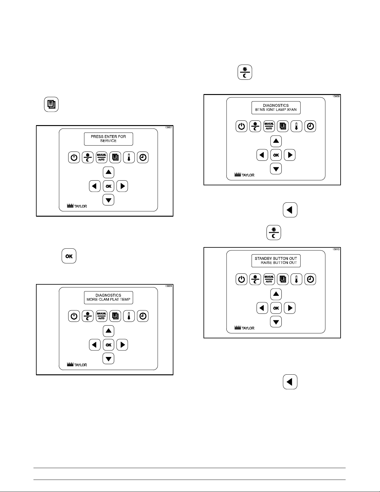
Service Diagnostics
Step 1
After the Service passcode has been entered, press
the key until the screen displays ”SERVICE”.
Figure 22
Step 2
MORE
Pressing the key will display the following
screen.
Figure 24
To exit this screen, press the key.
“BTNS” - Pressing the key will display:
Press the key to accept the selection. To
select the desired item, press the key below it.
Figure 23
Figure 25
Press the Standby/Raise buttons to verify the
operations of the buttons.
To exit this screen, press the key.
Controls and Systems
42
McDonald's Intelligap Grills
Page 49

“IGNT” - Pressing the key will display:
“XFAN” - Pressing the key will display the
following.
Figure 28
Figure 26
Note: This item only applies to gas grills. It is used
to verify that the grill is getting ignition.
To exit this screen, press the key.
“LAMP” - Pressing the key will display:
This item is used to adjust the exhaust fan speed.
To exit this screen, press the key.
CLAM
Pressing the key will display:
Figure 29
Figure 27
To exit this screen, press the key.
McDonald's Intelligap Grills
Press the key to raise the platen. Press the
key to lower the platen. This item is used to
verify that the latch switch is operational.
To exit this screen, press the key.
43
Controls and Systems
Page 50

PLAT
Pressing the key will display:
If all three motors are working correctly and have
auto-leveled, the screen will display “NOW >
LEVEL.”
Figure 32
Figure 30
“LEVL” - The LEVL key is used to level the platen.
The platen must be latched from the “CLAM” screen.
After the platen is latched, press the key to go
to the “LEVL” screen. Pressing the LEVL key will
prompt the platen motors to level. The screen will
display, “NOW > BUSY.”
Figure 31
If a motor does not operate correctly, the screen will
display “NOW > LOST.”
Figure 33
To exit this screen, press the key.
“HOME” - Pressing the key will bring the
platen to the HOME position. The screen will
display, “NOW > HOME.”
Controls and Systems
44
McDonald's Intelligap Grills
Page 51

Figure 34
To exit this screen, press the key.
“MORE” - Pressing the key displays:
“STOP” - Pressing the key will manually stop
the signal to the platen motors. To exit this screen,
press the key.
TEMP
Pressing the key will display:
Figure 36
Figure 35
Selecting “MANU” allows the technician to move the
upper platen (3 motors) to a specific gap. This can
be used to determine if the motors are moving
accurately from one position to the next by
measuring the gap at the first position and then at
the second position.
Selecting “AUTO” can be used to measure the
thickness of a standard disk. The control displays
the product which falls within that measurement and
also the data captured for each motor. This can be
used to identify a motor which is not performing to
specification.
To exit this screen, press the key.
“TOP” - Pressing the key under “TOP” will
display the “TOP TEMPS.”
Figure 37
Pressing the key below each zone will activate or
de-activate each heater. (Note: Temperatures
cannot be calibrated from this menu.)
IMPORTANT: Remember to shut the heater off.
To exit this screen, press the key.
McDonald's Intelligap Grills
45
Controls and Systems
Page 52

“BOT” - Pressing the key under “BOT” will
display the following screen.
Figure 38
Pressing the key below each zone will activate or
de-activate each heater. (Note: Temperatures
cannot be calibrated from this menu.)
“AUX” - Pressing the key under “AUX” will
display the following screen.
Figure 39
IMPORTANT: Remember to shut the heater off.
To exit this screen, press the key.
“AUX” has been added for future features of the grill.
To exit this screen, press the key.
Controls and Systems
46
McDonald's Intelligap Grills
Page 53

LonWorks® Gateway
LONWorks® Gateway is a “Smart Equipment”
networking solution for McDonald's, utilizing existing
power lines to transmit data instead of Ethernet
cabling. The LONWorks® Gateway will collect data
from the equipment and send information to a
computer in the back room. Users will be able to
monitor all “Smart Equipment” from a centralized
console. “Smart Enabled“ units will have the ability
to change programming/set up in the equipment.
Currently, the device is not activated or being used.
McDonald's Intelligap Grills
Figure 40
47
The gateway is installed in our equipment near the
power entry point. A separate 40VA transformer and
a Corcom filter provide the power to the LON®
Gateway, using 2-1/4” spade terminals. This option
is for future use to activate the gateway, and is not
being used at this time.
LED Lights:
PKD (Packet Detect) - Light flashes when receiving
messages.
SVC (Service) - Steady flashing means unit is
deactivated.
Controls and Systems
Page 54

Enabling LonWorks® Gateway
Step 9
IMPORTANT! The Gateway must be enabled on
all three control panels. Repeat the following
steps for each control panel.
Step 1
While in the AM/PM Mode, access the Control Menu
by pressing the key to display
“PROGRAMMING.”
Step 2
Press the key to display the passcode entry
screen.
Step 3
Enter the Control Menu passcode by pressing the
keys in this order:
Press the key to exit the programming mode.
Step 10
Repeat Steps 1 - 9 to enable the Gateway on the
second and third control panels.
Step 11
Shut off the grill for 30 seconds before attempting to
send a service pin.
Sending Service Pin From Menu
Step 1
While in the AM/PM Mode, access the Control Menu
by pressing the key to display
“PROGRAMMING.”
Step 2
Press the key to display the passcode entry
screen. (Note: No passcode is required. Proceed to
the next step.)
Step 3
Step 4
Press the key repeatedly until “SYSTEM SET
UP” displays.
Step 5
Press the key to scroll to “GATEWAY
ENABLED Y or N” (YES or NO).
Step 6
Press the key to change to “Y” (YES).
Step 7
Press the key.
Step 8
Press the key.
Press key until the SOFTWARE VERSION is
displayed.
Step 4
Press the key until the GATEWAY VERSION
number appears.
Note: If question marks appear instead of the
Gateway version number, wait a few seconds. If the
version number does not appear, shut the machine
off. After approximately 30 seconds, restart the
machine and repeat Steps 1 - 4.
Step 5
Press the key to send the service pin.
Step 6
Press the key.
Step 7
Press the key to exit the programming mode.
140922
Controls and Systems
48
McDonald's Intelligap Grills
Page 55

Sending Service Pin From LonWorks®
Gateway
USE CAUTION when accessing the
LonWorks® Gateway. HIGH VOLTAGE FUSES
ARE EXPOSED. Failure to follow this instruction
may result in severe personal injury from electrical
shock.
The Service Pin can also be sent from the
LonWorks® Gateway by pressing the service pin
button. (See Figure 40 on page 47.)
“Wink” Network Commissioning Tool
A network commissioning process tool called the
“wink” function can be initiated over the existing user
interface to identify a piece of equipment. When the
“wink” command is received through the network for
the grill, an alarm will sound at maximum volume for
two seconds.
McDonald's Intelligap Grills
49
121219
Controls and Systems
Page 56

Software Loading Procedures
IMPORTANT: After loading new software, the
gap, volume, and temperature settings will be at
the default factory settings.
Step 1
Record the present settings for system setup
and key menu items.
a. Turn the Fan Interlock Switch to the ON position.
b. While “OFF” is displayed, press the key
and enter the Service Menu passcode.
c. Press the key until “SYSTEM SETUP” is
displayed.
d. Press the key. The display will read
“PROBE CALIBRATION/TOP BACK.”
e. Record the offset.
h. Repeat until all offsets are recorded and then
press the key.
i. Press the key until the screen displays
“GAP CALIBRATION.”
j. Document the settings for the right side.
k. Press the key to go to the front and left
sides. Document all settings.
Step 2
Download the new software.
a. Place the Fan Interlock Switch in the OFF
position.
b. Remove the screw on the right and left edge of
the lower front panel to allow the panel to swing
down.
c. Loosen one screw on the back of the control to
allow the access door to swing open.
f. Press the key to display “PROBE
CALIBRATION/TOP FRONT.”
g. Record the offsets.
d. Insert the program module into the receptacle
located under the door. (See Figure 41.)
e. Swing the lower front panel up to view the
display.
140922
Controls and Systems
Figure 41
50
McDonald's Intelligap Grills
Page 57

f. Turn the Fan Interlock Switch to the “ON”
position.
l. When the software download is complete, “OFF”
will be displayed.
g. While “OFF” is displayed, press the key
and enter the Service Menu passcode.
h. Press the key until “SOFTWARE
VERSIONS” is displayed.
i. Press the key until the display flashes
“Software Versions on PGM Module Chip X”.
j. Press the key to start the download.
k. If the key was pressed while the display
flashed “Software Versions on PGM Module Chip
1”, the display will show a count-up sequence.
If the key was pressed while the display
flashed “Software Versions on PGM Module Chip
2”, the display will go blank for one or two
minutes while the software is loaded. The other
displays will remain on. DO NOT TURN THE
INTERLOCK SWITCH OFF.
m. Turn the Fan Interlock Switch to the “OFF”
position.
n. Remove the program module and secure the
access door on the control.
o. Swing the lower front panel up and secure it.
Step 3
Re-program the control, using the previously
recorded settings.
a. After entering the gap settings, make sure to
save and auto-level the platens.
b. Verify the temperature and gap settings.
Step 4
Program the correct date and time.
McDonald's Intelligap Grills
51
140922
Controls and Systems
Page 58

Electrical Power Distribution
The left high voltage powers the left upper platen,
the left lower plate, and the middle front and center
zones of the lower plate.
The right high voltage powers the right upper platen,
the right lower plate, the middle upper platen, and
the middle rear zone of the lower plate.
Controls and Systems
Figure 42
52
McDonald's Intelligap Grills
Page 59

Amp Draw
C832 Domestic Grill
The following table indicates the typical amp draw for the Model C832 (208/60/3):
C832 Grill Cord 1 Cord 2
Left Side of Grill L1L2 L2L3 L1L3 L1L2 L2L3 L1L3
Lower Front Plate
Lower Middle Plate
Lower Rear Plate
Top Back Platen
Top Front Platen
Totals
Right Side of Grill L1L2 L2L3 L1L3 L1L2 L2L3 L1L3
Lower Front Plate
11.06
11.06
11.06
4.97 4.97
4.97
11.06
Lower Middle Plate
Lower Rear Plate
Top Back Platen
4.97 4.97
Top Front Platen
Totals
Combined Totals 27.8 27.8 27.8 27.8 27.8 27.8
C832/C834 International Grill
The following table indicates the typical amp draw for the Model C832/C834 (230400/50/3):
C832/C834 Grill Cord 1 Cord 2
Left Side of Grill L1N L2N L3N L1N L2N L3N
Lower Front Plate
Lower Middle Plate
Lower Rear Plate
Top Back Platen
Top Front Platen
Totals
Right Side of Grill L1N L2N L3N L1N L2N L3N
10.0
10.0
10.0
4.49 4.49
4.49
11.0
6
11.06
4.97
Lower Front Plate
Lower Middle Plate
Lower Rear Plate
Top Back Platen
Top Front Platen
Totals
Combined Totals 20.0 14.5 9.0 9.0 14.5 20.0
McDonald's Intelligap Grills
53
10.0
10.0
10.0
4.49 4.49
4.49
Controls and Systems
Page 60

C835 Domestic Grill
The following table indicates the typical amp draw for the Model C835 (208/60/3):
Note: It is not possible to connect the heaters as a balanced 3phase load on this model. For simplification, the
heater loads are calculated using the highest load from one phase for ALL phases.
C835 Grill Cord 1 Cord 2
Left Side of Grill L1L2 L2L3 L1L3 L1L2 L2L3 L1L3
Lower Front Plate
5.29
Lower Middle Plate
Lower Rear Plate
Top Back Platen
Top Front Platen
Totals
Right Side of Grill L1L2 L2L3 L1L3 L1L2 L2L3 L1L3
Lower Front Plate
4.97 4.97
4.97
5.29
Lower Middle Plate
Lower Rear Plate
Top Back Platen
Top Front Platen
Totals
Combined Totals 13.9 13.9 13.9 13.9 13.9 13.9
4.97 4.97
4.97
C835 International Grill
The following table indicates the typical amp draw for the Model C835 (230400/50/3):
Note: It is not possible to connect the heaters as a balanced 3phase load on this model. For simplification, the
heater loads are calculated using the highest load from one phase for ALL phases.
C835 Grill Cord 1 Cord 2
Left Side of Grill L1N L2N L3N L1N L2N L3N
Lower Front Plate
Lower Middle Plate
Lower Rear Plate
Top Back Platen
Top Front Platen
Totals
Right Side of Grill L1N L2N L3N L1N L2N L3N
Lower Front Plate
Lower Middle Plate
Lower Rear Plate
Top Back Platen
Top Front Platen
Totals
Combined Totals 9.8 14.0 13.8
Controls and Systems
4.99
4.78
8.99
4.99
54
4.78
8.99
McDonald's Intelligap Grills
Page 61

C842 Domestic Grill
The following table indicates the typical amp draw for the Model C842 (208/60/3):
C842 Grill Cord 1 Cord 2
Left Side of Grill L1L2 L2L3 L1L3 L1L2 L2L3 L1L3
Lower Front Plate
Lower Middle Plate
Lower Rear Plate
Top Back Platen
Top Front Platen
Totals
Middle of Grill L1L2 L2L3 L1L3 L1L2 L2L3 L1L3
Lower Front Plate
Lower Middle Plate
9.13
6.25
6.25
9.13
9.13
Lower Rear Plate
Top Back Platen
Top Front Platen
Totals
Right Side of Grill L1L2 L2L3 L1L3 L1L2 L2L3 L1L3
Lower Front Plate
Lower Middle Plate
Lower Rear Plate
Top Back Platen
Top Front Platen
Totals
Combined Totals 37.5 31.6 31.6 31.6 37.5 37.5
9.13
9.13
9.13
6.25
6.25
9.13
9.13
9.13
6.25
6.25
McDonald's Intelligap Grills
55
Controls and Systems
Page 62

C842/844 International Grill
The following table indicates the typical amp draw for the Model C842/844 (230400/50/3):
C842/844 Grill Cord 1 Cord 2
Left Side of Grill L1N L2N L3N L1N L2N L3N
Lower Front Plate
Lower Middle Plate
Lower Rear Plate
Top Back Platen
Top Front Platen
Totals
Middle of Grill L1N L2N L3N L1N L2N L3N
Lower Front Plate
Lower Middle Plate
Lower Rear Plate
Top Back Platen
Top Front Platen
Totals
Right Side of Grill L1N L2N L3N L1N L2N L3N
Lower Front Plate
Lower Middle Plate
Lower Rear Plate
Top Back Platen
Top Front Platen
Totals
Combined Totals 17.8 14.2 14.2 14.2 17.8 17.8
7.1
7.1
7.1
5.33
5.33
7.1
7.1
7.1
5.33
5.33
7.1
7.1
7.1
5.33
5.33
Controls and Systems
56
McDonald's Intelligap Grills
Page 63

C845 Domestic Grill
The following table indicates the typical amp draw for the Model C845 (208/60/3):
C845 Grill Cord 1 Cord 2
Left Side of Grill L1L2 L2L3 L1L3 L1L2 L2L3 L1L3
Lower Front Plate
Lower Middle Plate
Lower Rear Plate
Top Back Platen
Top Front Platen
Totals
Middle of Grill L1L2 L2L3 L1L3 L1L2 L2L3 L1L3
Lower Front Plate
Lower Middle Plate
Lower Rear Plate
Top Back Platen
Top Front Platen
Totals
Right Side of Grill L1L2 L2L3 L1L3 L1L2 L2L3 L1L3
Lower Front Plate
Lower Middle Plate
Lower Rear Plate
Top Back Platen
Top Front Platen
Totals
Combined Totals 21.6 21.6 21.6
6.25
6.25
6.25
6.25
6.25
6.25
McDonald's Intelligap Grills
57
Controls and Systems
Page 64

C845 International Grill
The following table indicates the typical amp draw for the Model C845 (230400/50/3):
C845 Grill Cord 1 Cord 2
Left Side of Grill L1N L2N L3N L1L2 L2L3 L1L3
Lower Front Plate
Lower Middle Plate
Lower Rear Plate
Top Back Platen
Top Front Platen
Totals
Middle of Grill L1L2 L2L3 L1L3 L1L2 L2L3 L1L3
Lower Front Plate
Lower Middle Plate
Lower Rear Plate
Top Back Platen
Top Front Platen
Totals
Right Side of Grill L1L2 L2L3 L1L3 L1L2 L2L3 L1L3
Lower Front Plate
Lower Middle Plate
Lower Rear Plate
Top Back Platen
Top Front Platen
Totals
Combined Totals 11.3 11.3 11.3
5.65
5.65
5.65
5.65
5.65
5.65
Controls and Systems
58
McDonald's Intelligap Grills
Page 65
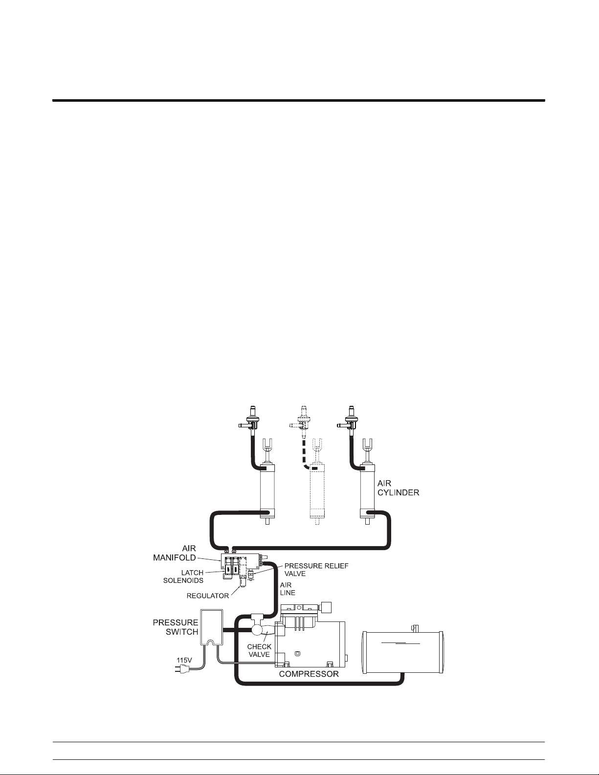
Pneumatic System
Compressor and Accumulator
The compressor pumps air into the accumulator,
building the pressure in the accumulator to 60 psi
(414 kPa).
Check Valve
The check valve is a “one‐way” valve which allows
the compressor to start under a no load condition.
When the compressor stops operating, the check
valve also allows pressure to exhaust between the
compressor and the valve itself.
Pressure Switch
When air pressure has left the accumulator, the
pressure switch recognizes this and activates the
compressor again. Generally, the platen can be
raised 4-5 times between compressor cycles.
The pressure switch for the three platen grills closes
at 67 psi (462 kPa) and opens at 47 psi (324 kPa).
The pressure switch for the two platen grills closes
at 60 psi (414 kPa) and opens at 35 psi (241 kPa).
Relief Valve
The relief valve ensures that accumulator pressure
does not exceed 70 lbs (483 kPa).
Regulator
Regulates the pressure necessary to hold the upper
platen in the closed position at 35 psi (241 kPa).
Latch Solenoid
When activated, the latch solenoid opens the flow of
air pressure which holds the air cylinder plunger in
the raised position. This plunger keeps the upper
platen in its closed position during the cook time.
Air Cylinder
When cook times elapse, the air cylinder dampens
the opening of the upper platen.
McDonald's Intelligap Grills
Figure 43
59
150402
Controls and Systems
Page 66

Model C835 & C845 Gas Connections
To ensure proper operation, the Model C835 and
C845 gas grills require a minimum pipe size of 1
inch (25 mm). For propane gas, the next lower size
can be used. If in doubt, contact the local gas
company.
The grill must be connected to the existing gas
supply lines with the hose assembly included in the
accessory package.
All gas line connections and plumbing
must be inspected for leaks by using an electric
leak detector or a soap solution.
Gas Regulator Inspection
Step 1
Disconnect all power to the grill. Failure
to follow this instruction may result in electrical
shock.
Step 2
Step 9
After all heat zones are turned on, verify the gas
regulator settings:
Domestic:
Regulator Setting Tolerance
Natural Gas ‐ 3.5” w.c. 3.2 - 3.8
Propane Gas ‐ 10.5” w.c. 9.5 - 11.5
Note: Domestic gas regulators must NOT be
adjusted. If the pressure adjustment deviates from
the tolerance range, the valve must be replaced.
International:
See Figure 44 on page 61.
IMPORTANT: Regulators should be inspected
separately.
Step 10
Remove all power, turn off the gas supply, and
re‐install the MPT plug, using an approved sealant.
Turn off all gas supply. Failure to comply
can result in a fire hazard.
Step 3
Remove the MPT plug from the gas manifold.
Step 4
Install a barbed fitting.
Step 5
Connect a water column pressure gauge to the gas
manifold.
Step 6
Connect the power and gas supply.
Step 7
Turn on the grill.
Step 8
Turn on each heating zone, one at a time.
Orifice Size
C835 Domestic:
Natural Gas 34
Propane Gas 52
C845 Domestic:
Natural Gas 40
Propane Gas 53
C835 & C845 International:
See Figure 44 on page 61.
Controls and Systems
60
McDonald's Intelligap Grills
Page 67

Approved Gases for Europe - Model C835
Single Categories Double Categories
Gas Category:
Reference Gas:
AT‐Austria
Supply Pressure 20 mbar 50 mbar 20/50 mbar
Orifice Size 2.8 mm 2.0 mm 2.8/2.0 mm
Orifice PN 76554‐280 76554‐200 76554‐***
Burner Pressure 7.0 mbar 8.0 mbar 7.0/8.0
BE‐Belgium,
FR‐France
Supply Pressure
Orifice Size
Orifice PN
Burner Pressure
DE‐Germany
Supply Pressure 20/25 mbar 50 mbar (20/25)/50
Orifice Size 2.8 mm 2.0 mm (2.8
Orifice PN 76554‐280 76554‐200 76554‐***
Burner Pressure 7.0/10.0
See Note:**
Supply Pressure 20 mbar
Orifice Size 2.8 mm
Orifice PN 76554‐280
Burner Pressure 7.0 mbar
I
2E
G20 G20 G20, G25 G25 G30, G31 G31 G20, G30,
I
2H
I
mbar
2ELL
I
2L
I
3B/P
8.0 mbar (7.0/10) /
I
3P
II
2E3B/PII2ELL3B/PII2H3B/P
G31
G20, G25,
G30, G31
mbar
mm)/2.0
mm
8.0 mbar
G20, G30,
G31,
mbar
II
2L3P
G25, G31
LU‐Luxembourg
Supply Pressure 20 mbar 50 mbar 20/50
Orifice Size 2.8 mm 2.0 mm 2.8/2.0 mm
Orifice PN 76554‐280 76554‐200 76554‐***
Burner Pressure 7.0 mbar 8.0 mbar 7.0/8.0
NL‐Netherlands
Supply Pressure 25 mbar 30/50 mbar 25/(30/50)
Orifice Size 2.8 mm 1.7 mm 2.8/1.7 mm
Orifice PN 76554‐280 76554‐170 76554‐***
Burner Pressure 10.0 mbar 19.8 mbar 10.0/19.8
mbar
mbar
mbar
mbar
Figure 44
* These gas categories appear on the official Gastec Certificate E7305, August 28, 2009
** DK-Denmark, ES-Spain, F1-Finland, GB-Great Britain, GR-Greece, IE-Ireland, IT-Italy, NO-Norway,
PT-Portugal, SE-Sweden, CH-Switzerland
*** The last 3 digits of the Taylor part number correspond to the supply pressure/orifice part number shown in the
single gas category.
120807
McDonald's Intelligap Grills
61
Controls and Systems
Page 68

Approved Gases for Europe - Model C845
Single Categories Double Categories
Gas Category:
Reference Gas:
AT-Austria
Supply Pressure 20 mbar 50 mbar 20/50 mbar
Orifice Size 2.5 mm 1.7 mm 2.5/1.7 mm
Orifice PN 76554-40 76554-51 76554-***
Burner Pressure 7.0 mbar 8.0 mbar 7.0/8.0
BE-Belgium,
FR-France
Supply Pressure
Orifice Size
Orifice PN
Burner Pressure
DE-Germany
Supply Pressure 20/25 mbar 50 mbar (20/25)/50
Orifice Size 2.5 mm 1.7 mm 2.5/1.7 mm
Orifice PN 76554-40 76554-51 76554-***
Burner Pressure 7.0/10.0
See Note:**
Supply Pressure 20 mbar
Orifice Size 2.5 mm
Orifice PN 76554-40
Burner Pressure 7.0 mbar
I
2E
G20 G20 G20, G25 G25 G30, G31 G31 G20, G30,
I
2H
I
mbar
2ELL
I
2L
I
3B/P
8.0 mbar (7.0/10) /
I
3P
II
2E3B/PII2ELL3B/PII2H3B/P
G31
G20, G25,
G30, G31
mbar
8.0 mbar
G20, G30,
G31,
mbar
II
2L3P
G25, G31
LU-Luxembourg
Supply Pressure 20 mbar 50 mbar 20/50
Orifice Size 2.5 mm 1.7 mm 2.5/1.7 mm
Orifice PN 76554-40 76554-51 76554-***
Burner Pressure 7.0 mbar 8.0 mbar 7.0/8.0
NL-Netherlands
Supply Pressure 25 mbar 30/50 mbar 25/(30/50)
Orifice Size 2.5 mm 1.7 mm 2.5/1.7 mm
Orifice PN 76554-40 76554-51 76554-***
Burner Pressure 10.0 mbar 11.0 mbar 10.0/11.0
mbar
mbar
mbar
mbar
Figure 45
* These gas categories appear on the official Gastec Certificate TBD (To Be Determined)
** DK-Denmark, ES-Spain, F1-Finland, GB-Great Britain, GR-Greece, IE-Ireland, IT-Italy, NO-Norway,
PT-Portugal, SE-Sweden, CH-Switzerland
*** The last 3 digits of the Taylor part number correspond to the supply pressure/orifice part number shown in the
single gas category.
120807
Controls and Systems
62
McDonald's Intelligap Grills
Page 69

Model C835 & C845 Heating System Operation - Domestic
Air Section
The fan operates.
Static pressure builds up and engages the static
pressure switch.
Air is distributed to the venturi tube.
The amount of air supplied to the burner is
controlled by the air adjustment rod.
Gas Section
Gas from the supply is regulated through the gas
regulator.
Gas is distributed through the gas solenoids.
Upon ignition, the solenoids remain open and gas is
supplied to the orifice on the burner venturi.
Burner Section
Air and gas is mixed in the burner venturi.
This mixture is forced through openings in the
burner and is ignited.
Combustion gases are released through the flue at
the rear of the grill.
McDonald's Intelligap Grills
Figure 46
63
120828
Controls and Systems
Page 70

Model C845 Heating System Operation - Pimple Pilot
Starting with serial number M2125255, the Model
C845 is built with the pimple pilot electrode.
Pimple Pilot Electrode
The pimple pilot is a style of electrode that
implements a gas line. The electrode ground rod is
replaced by a ground tube. The tube serves two
purposes. It operates as a ground for the spark and
it directs a small amount of raw gas (not mixed with
air) to the spark gap to create a pilot flame. A bridge
has been added to ensure the spark gap remains
fixed over time.
Air Section
The fan operates. Static pressure builds up and
engages the static pressure switch. Air is distributed
to the venturi tube. The amount of air supplied to the
burner is controlled by the air adjustment rod.
Gas Section
The pimple pilot gas line is connected to the grill's
gas supply after the gas valves and before the
blower. A 90 degree integral orifice regulates the
gas to the pimple pilot.
Gas from the supply is regulated through the gas
regulator. Gas is distributed through the gas
solenoids to the burner and the gas pilot electrode.
Upon ignition, the solenoids remain open and gas is
supplied to the orifice on the burner venturi and
pimple pilot.
Burner Section
Air and gas is mixed in the burner venturi. This
mixture is forced through openings in the burner and
is ignited. Combustion gases are released through
the flue at the rear of the grill.
The pimple pilot system also includes a new lower
burner. The burner iincludes a formed-in grounding
screen. The incorporated screen increases the
sensitivity to the flame sense signal.
130605
Controls and Systems
Figure 47
64
McDonald's Intelligap Grills
Page 71

Model C835 & C845 Ignition Detection Control - Domestic
The gas grills contain an Ignition Detection
Control (IDC) which is responsible for generating a
high voltage spark. The IDC Board has three
functions:
S Opens the gas solenoid
S Creates a spark
S Provides a lockout safety feature
Lockout
If the flame is not detected, the ignition probe will not
receive flame sense current and the gas solenoid
will close. The unit will lock out and “Blower Failure”
will be displayed.
McDonald's Intelligap Grills
Figure 48
65
130619
Controls and Systems
Page 72

High Voltage Gas System - IDC Overview
Ignition Detection Control
(International)
The International grill models contain an Ignition
Detection Control (IDC) which is responsible for the
ignition and monitoring of the gas burner system.
The Fenwal IDC operates with a single trial ignition
sequence. The IDC board has four functions.
S Turning blower on/off
S Opens gas solenoid
S Creates a spark
S Provides lockout safety features
System Overview
Call for Heat
When a call for heat is received from the Motor
Control Board 24 Volts are sent to TH/W. The IDC
will then check for normally open contacts at the
pressure switch. The blower is then turned on and
the control checks the pressure switch to ensure it is
closed, and the prepurge of the burner begins. Next
the gas solenoids are energized and the IDC starts
its single trial ignition.
Ignition (Single Ignition)
When flame is detected during the ignition the IDC
stops sending voltage to the electrode. The blower
and gas solenoid remain energized. The IDC
monitors the 24 MCB input, pressure switch position
(Closed) and the presence of flame in the burner
(Flame Sense). When the call for heat is satisfied
(TH/W will receive a low signal from MCB) the gas
solenoid closes, the IDC monitors the loss of flame
sense and the blower is deenergized.
IDC Fault Codes
The Fenwal IDC is equipped with system fault
detection. The fault modes are then expressed
through the IDC’s LED. The following section will
cover the failures and their correlating LED
sequences. The LED will flash on for a ¼ of a
second and off for a ¼ of a second. The pause
between fault codes is 3 seconds.
Internal Control Failure (LED stays on)
This occurs when the IDC has an internal
component failure. The fault can be reset by cycling
the power of the grill. If the IDC continues to display
the fault after cycling the power the IDC will have to
be replaced.
Air Flow Fault (LED Flashes 1 time)
1. During the ignition sequence the IDC monitors
the blower air flow by monitoring the of the
pressure switch (pressure switch must be in
closed position). If the grill is calling for heat
and the pressure switch is closed for 30
seconds without the blower being energized,
the IDC will go into an air flow fault. The control
will remain in this lockout and the blower will be
off.
2. If the pressure switch stays open for 30
seconds after the blower is energized a fault
will be displayed. The blower will remain on
waiting for the pressure switch to close. When
pressure builds and close the switch, the IDC
will begin its normal ignition trial. If pressure
from the blower does not build the IDC will
remain in this fault mode.
3. If the pressure switch opens during a heat cycle
the gas valve will be deenergized and the
blower will remain on. If the pressure switch
does not close with 30 seconds a fault will be
displayed.
130612
Controls and Systems
66
McDonald's Intelligap Grills
Page 73

Flame Fault (LED flashes 2 times)
Flame Failure Reignition
If the gas solenoid fails to close completely and the
burner stays lit, the flame sense circuit will detect it
and energize the blower. The blower will remain on
until the gas valve closes and the flame sense is
lost.
Ignition Lockout (LED flashes 3 times)
This section will cover the Failure to Ignite,
Reignition and Lockout Reset.
This IDC has a single trial ignition. If the burner fails
to light or the flame sense is not detected during
ignition, the control will lockout. When the control
goes into this lockout the gas solenoid and blower
will be turned off.
If the burner is lit and it goes out (Flame Sense is
lost) the control will try to reignite within 0.8
seconds. If the burner fails to ignite the IDC will go
into Ignition Lockout. If the burner does light during
the reignition sequence, the control will operate as
normal.
Lockout Reset
When the IDC goes into lockout it must be manually
reset. This is accomplished by removing the 24 Volt
input from 24VAC(R) for 5 seconds.
McDonald's Intelligap Grills
67
Controls and Systems
Page 74

Fenwal IDC Pin Configuration
Pin Description
24VAC/R 24 VAC supply to processor (MCB Output)
TH/W Thermostat input (MCB Output)
PSW Pressure Switch Input
GND System Ground
V1 Gas Valve Power (Output) to Relay
V2 Valve ground
Pin Description
L1 120/240 VAC Input (Hot)
IND/V1 Inducer Blower (Output)
NC Alarm (Normally closed contacts)
S1 Remote Flame Sensor
FC+, FC Flame current test pins
Controls and Systems
Figure 49
68
McDonald's Intelligap Grills
Page 75

Circuit Overview
1. When a MCB calls for heat the MCB sends a
24 volt signal to TH/W. This initiates the ignition
sequence.
2. The IDC then checks the position of the
pressure switch. At this stage of the sequence
the pressure switch should be open.
3. Once the open position of the pressure switch
is verified the IDC sends 220VAC to the blower
motor.
a. The first is a volt signal is send from the 12
IDC Output (On MCB) to contact 12 on
relay. When the relay closes the 12 volt
signal comes out of contact 8 and it sent to
J4 Pin 10.
1. The feedback to the J4 Pin 10
connection tells the board that the
system is in working order. If this
signal does not return to the Pin 10
connection the MCB will assume there
is a failure in the system, and cut
power to the IDC resulting in a
BLOWER failure.
b. The second function of the relay is to
connect L1 to the gas solenoid.
4. Once the blower is energized the IDC
rechecks the pressure switch to ensure it is in
the closed position.
5. The high voltage signal is now sent to the
electrode for ignition
6. Next V1 output is sent to the gas system’s
relay. When the coil of the relay is energized
two sets of contacts are closed. The relay has
two functions in this system.
7. Once the burner lights, the IDC removes the
voltage to the electrode and monitors the 24
MCB input, pressure switch position (Closed)
and the presence of flame in the burner (Flame
Sense).
8. When the call for heat is satisfied the MCB will
cut power to TH/W.
9. The IDC will recognize the heat cycle is over
and deenergizes the gas system relay. The
IDC monitors the loss of the flame sense
signal. When the signal is lost (Flame has gone
out) the IDC deenergizes the blower motor.
McDonald's Intelligap Grills
69
Controls and Systems
Page 76

Flame Sense Current Test (high voltage international models only)
Flame Sense is the current that passes through the
flame from the electrode to ground. The flames
coming off of the burner complete the circuit from
electrode to ground. If the circuit is not completed
the IDC assumes there is no flame. The minimum
flame sense current needed is .7μA. The following
step will cover the test procedure.
Figure 50
1. To measure the flame sense current connect a
multimeter (with Micro Amp capability) to the
FC+ (Positive meter probe) and FC (Negative
meter probe).
2. The burner must be lit to measure current. This
is accomplished by manually turning the burner
on from the service menu.
Note: The polarity of the meter probes matters in
this test. If the probes are reversed the current
reading will be incorrect.
Controls and Systems
70
McDonald's Intelligap Grills
Page 77

C832/C834/C835 (Two Platen Models) Exhaust Hoods
McDonald's Intelligap Grills
Figure 51
71
Controls and Systems
Page 78

C842/C844/C845 (Three Platen Models) Exhaust Hoods
Controls and Systems
Figure 52
72
McDonald's Intelligap Grills
Page 79

Section 3: Troubleshooting
S General Troubleshooting
S Error Messages
S Troubleshooting Charts
S Motor/Platen Troubleshooting
S Meat Quality Troubleshooting
McDonald's Intelligap Grills
73
Troubleshooting
Page 80
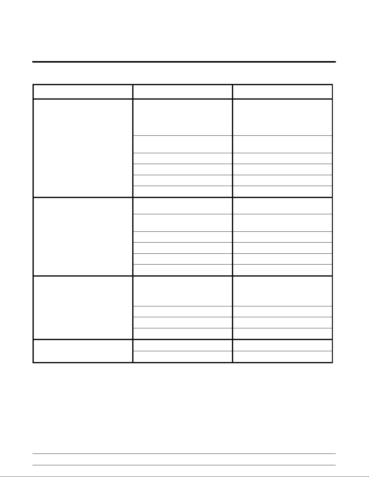
General Troubleshooting Guide
All Models
PROBLEM PROBABLE CAUSE REMEDY
One side of the clamshell grill will
not heat. The control displays the
message, “UPPER HEATER
FAILURE” or “LOWER HEATER
FAILURE”.
One side of the clamshell grill will
not heat.
One power connection is not
connected.
The restaurant circuit breaker has
tripped.
The contactor is faulty. Replace the contactor.
The heater is faulty. Replace the heater.
The high limit switch is faulty. Replace the high limit switch.
The solid state relay is faulty. Replace the solid state relay.
Check the power connection.
Reset the restaurant circuit
breaker.
Check the power connection.
Reset the restaurant circuit
breaker.
One heat zone will not heat. Heater is not turning on or is
heating too slowly. The power cord
may have come loose or partially
unplugged at wall receptacle.
The interface board is faulty. Replace the interface board.
The solid state relay is faulty. Replace the solid state relay.
The control harness is faulty. Replace the control harness.
One of the heat zones is
overheating. (The display reads
“TOO HOT”.)
160125
Troubleshooting
The interface board is faulty. Replace the interface board.
The solid state relay is faulty. Replace the solid state relay.
74
Check the plug receptacle and
re-seat the connection.
McDonald's Intelligap Grills
Page 81

All Models (Cont'd.)
PROBLEM PROBABLE CAUSE REMEDY
The display reads “TOO COOL”
(Zone ID) and will not allow a cook
cycle to start.
This error message displays when
a zone drops 39 degrees below set
point.
The exhaust hood and grill will not
turn on when fan interlock switch is
placed in the ON position.
The exhaust hood alone does not
turn on when the fan interlock
switch is in the ON position.
Loose frozen product (e.g., onions,
shrimp) is being piled on top of the
thermocouples. This can drop the
plate temperature around the
thermocouple, causing a fault.
Frozen whole muscle product
(chicken breast) may cause this
fault if too many are placed on the
grill or directly over the
thermocouples.
The restaurant circuit breaker has
been tripped.
The fan disconnect switch on the
roof is in the OFF position.
The fan interlock cord is not
connected properly.
The fan interlock switch is faulty. Replace the fan interlock switch.
The fan interlock switch is faulty. Replace the fan interlock switch.
Inspect operation and inform the
operator to spread the product to a
uniform thickness. Avoid laying
product directly over the center of
the cook zone (where the
thermocouples are positioned).
Inspect operation and inform the
operator to reduce the number of
products being laid. Show the
operator how to properly place
product, avoiding placement of
product directly over the
thermocouples.
Reset the circuit breaker.
Place the switch in the ON
position.
Reconnect the cord.
The grill alone will not turn on
when the fan interlock switch is in
the ON position.
The upper platen will not stay in
the COOK or STANDBY position.
Loose or broken wires. Locate, repair or replace wires.
The fuse in the control box is
faulty.
The fan interlock switch is faulty. Replace the switch.
The ansul reset tripped. Press the ansul reset button.
The processor control is faulty. Replace the processor control.
The control harness is faulty. Replace the control harness.
Temperature is insufficient to
satisfy the indicator LED's.
The interface board is faulty. Replace the interface board.
The latch switch is faulty. Replace the latch switch.
The latch solenoid is faulty. Replace the latch solenoid.
The pneumatic system is faulty. Find the leak and repair.
Replace the fuse.
Wait until the indicator LED's turn
green.
McDonald's Intelligap Grills
75
160122
Troubleshooting
Page 82

All Models (Cont'd.)
PROBLEM PROBABLE CAUSE REMEDY
The upper platen will not stay in
the COOK position, but will stay in
the STANDBY mode.
The upper platen will not stay in
the STANDBY mode, but will stay
in the COOK position.
The upper platen opens too
rapidly.
The display reads “UPPER
PLATEN STUCK”.
The display reads “PROBE
OPEN”.
The product is under‐cooked or
over-cooked.
The processor control is not set
properly.
Faulty wire connections. Repair wire connections.
Incorrect use of the STANDBY
button.
The orifice/check valve is incorrect
or missing.
The arm bearings are dirty. Replace the bearings.
The air cylinder is faulty. Replace the air cylinder.
Plugged air lines to cylinders. Replace the air lines.
The thermocouple or the motor
control board is faulty.
The release material sheet is worn. Replace the release material
The upper platen or lower grill
surface is not clean and/or has
carbon build‐up.
Check the time setting on the
processor control.
Press the STANDBY button within
five seconds of lowering the platen
into the COOK position.
Replace the check valve.
Replace the thermocouple or the
motor control board.
sheet.
Closing procedures must be
followed to properly clean the
upper platen and the lower grill
surface, and to remove carbon
build‐up.
Incorrect cooking time. Reset the processor control for the
Incorrect temperature. Adjust the processor control to the
The preset gap height is incorrect. Regap the grill.
The heating zone is not heating. Repair/replace the heater.
The product is not cooking evenly. The upper platen or lower grill
surface is not clean and/or has
carbon build‐up.
Release material sheet is worn. Replace release material sheet.
Air pressure is not high enough. Adjust air pressure to 30 psi.
The platen is not level. Relevel the platen.
The preset gap height is incorrect. Regap the grill.
correct time (check the Operations
and Training Manual).
proper setting.
Closing procedures must be
followed to properly clean the
upper platen and the lower grill
surface, and to remove carbon
build‐up.
Troubleshooting
76
McDonald's Intelligap Grills
Page 83
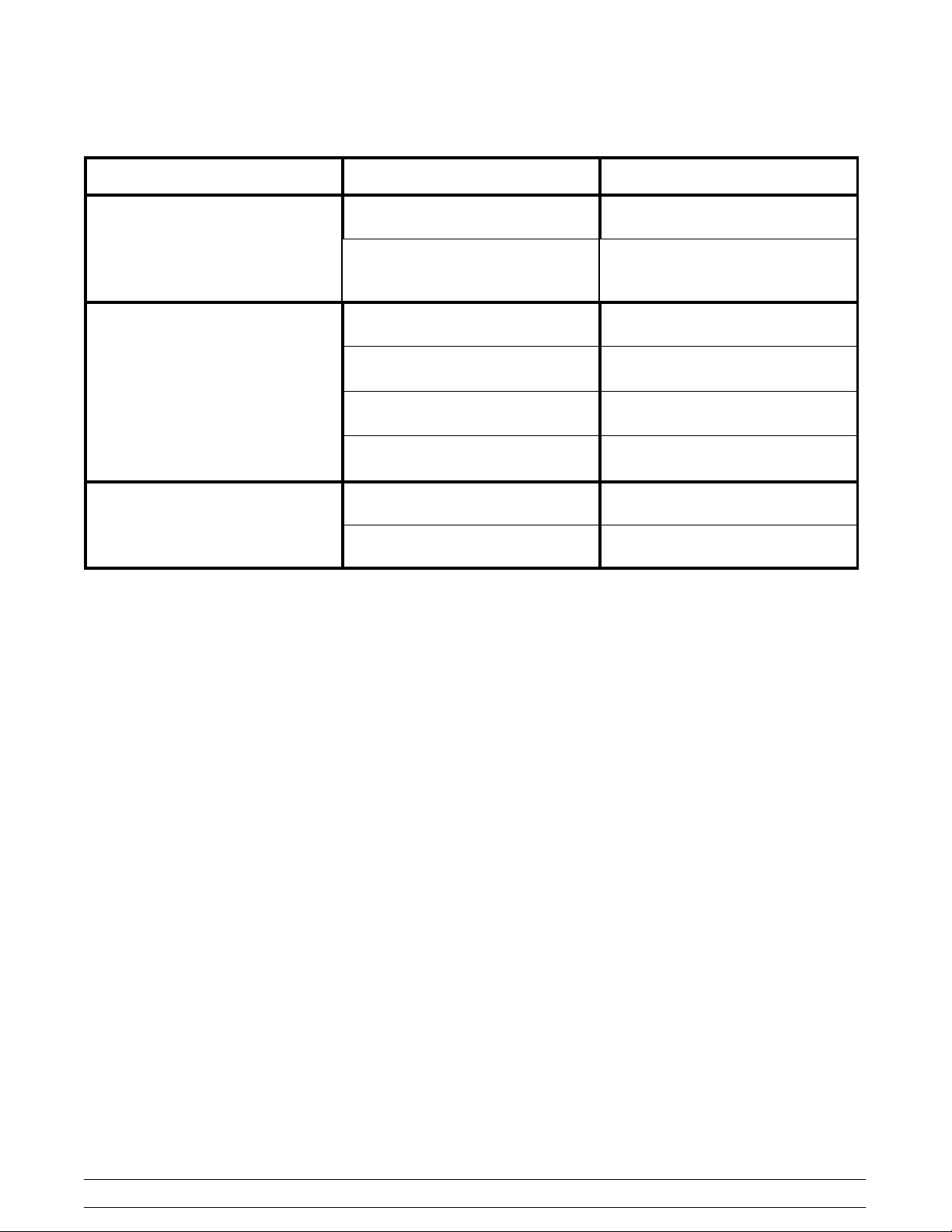
All Models (Cont'd.)
PROBLEM PROBABLE CAUSE REMEDY
The product is not recognized. The grill is not set in the Auto
Product Recognition mode.
The product is out of specification
(examples: freezer burned,
warped, too thick, or too thin).
The platen will not auto-level. Defective motors and cables. Check/replace the motors and
Defective motor interface board. Check/replace motor interface
Loose harness connections. Check/repair/replace harness
Defective main display controller. Check/replace main display
The automatic air drain will not
close.
Faulty solenoid. Repair/replace the solenoid.
Loose or broken wire. Locate and repair or replace the
Correct the product menu settings.
Use good product that is within
specification.
cables.
board.
connections.
controller.
wire.
McDonald's Intelligap Grills
77
Troubleshooting
Page 84

Model C835 and C845 Gas Zones Only
PROBLEM PROBABLE CAUSE REMEDY
The heater is not heating or is
heating too slowly. The display
reads “CALL FOR SERVICE - NO
HEAT IN ZONE XX.” (Zone ID)
This error message displays when
there is a call for heat but no
temperature rise in 4 minutes.
The display reads “BLOWER
FAILURE”.
The burner will not light. The
display reads “IGNITION
FAILURE”.
Upper Platen: The power cord is
loose or partially unplugged at the
wall receptacle.
Lower plate: The combustion ratio
of the burner is out of adjustment.
The blower is faulty. Replace the blower.
The IDC or the relay is faulty. Replace the IDC or the relay.
The pressure switch is faulty. Replace the switch.
The quick disconnect gas hose is
not fully engaged.
The manual shutoff valve is in the
OFF position.
The gas regulator is adjusted
incorrectly.
Air is in the gas hose. Wait 5 minutes before relighting.
The air adjustment is incorrect. Adjust the air flow.
The processor control is faulty. Replace the control.
Check the plug receptacle and
reset the connection.
Measure the CO/CO2 with the
combustion meter and adjust per
combustion meter instructions.
Re‐engage the quick disconnect.
Turn it to the ON position.
Correct the gas pressure.
The burner lights but will not
remain lit.
The Ignition Detection Control
(IDC) is faulty.
The pressure switch is faulty. Replace the pressure switch.
The flue restrictors are open too
wide.
The gas solenoid is faulty. Replace the solenoid.
The electrode is faulty. Replace the electrode.
The interface board is faulty. Replace the interface board.
The electrode is faulty. Replace the electrode. Clean and
The gas/air ratio is incorrect. Readjust the air shutter.
Improper ground. Check ground connections.
The IDC is faulty. Replace the IDC.
The flue restrictors are open too
wide.
L1 and Neutral are reversed on the
control power.
The pressure switch is faulty. Replace the pressure switch.
Replace the control.
The flue restrictors should be open
only 1/2” ‐ 3/4” (13 ‐ 19 mm).
adjust.
The flue restrictors should be open
only 1/2” ‐ 3/4” (13 ‐ 19 mm).
Reverse the L1 and Neutral.
160121
Troubleshooting
78
McDonald's Intelligap Grills
Page 85

Model C835 and C845 Gas Zones Only (Cont'd.)
PROBLEM PROBABLE CAUSE REMEDY
The burner lights but the zone is
cool or overheats.
Intermediate “IGNITION
TERMINATED” error message
displays.
This error message displays when
the J4 Pin 10 on the motor control
board doesn't receive 12VDC
within 10 seconds of the start of a
heat cycle.
The grill is out of calibration. Calibrate the grill.
The processor control is faulty. Replace the control.
The thermocouple or the
thermocouple interface board is
faulty.
Loose/dirty connections throughout
the gas system.
Broken hi-limit wire, due to
movement. There might be a short
that is only present when the
platen is moving up or down.
Replace the thermocouple or the
thermocouple interface board.
Clean all wire terminals in the gas
system with contact cleaner.
(Service bulletin S2691.) Inspect
all wire terminals and perform tug
test to make ensure proper
connections. If terminals are loose,
tighten the terminals with pliers or
replace them. The main areas to
focus on are the IDC header and
the gas valve terminal block
located on the back left frame post.
Using a meter, check for continuity
through the hi-limit wire from the
IDC to the gas valve terminal
block. Perform this test while the
platen is stationary in the up/down
position. Also test while manually
moving the platen up/down.
Replace any broken or shorted
wires. Inspect the hi-limit wire
routing to make sure it is not tied to
the wires from the high voltage or
thermocouple wires coming from
the upper platen.
McDonald's Intelligap Grills
79
160122
Troubleshooting
Page 86

Model C835 and C845 Gas Zones Only (Cont'd.)
PROBLEM PROBABLE CAUSE REMEDY
Intermediate “IGNITION
TERMINATED” error message
displays.
This error message displays when
the J4 Pin 10 on the motor control
board doesn't receive 12VDC
within 50 seconds of the start of a
heat cycle.
Loose/dirty connections throughout
the gas system.
Wires broken due to movement.
There might be a short that is only
present when the platen is moving
up or down.
Low gas pressure to unit. Measure the output gas pressure
The combustion ratio is incorrect. Measure the CO/CO2 with the
Clean all wire terminals in the gas
system with contact cleaner.
(Service bulletin S2691.) Inspect
all wire terminals and perform tug
test to make ensure proper
connections. If terminals are loose,
tighten the terminals with pliers or
replace them. The main areas to
focus on are the IDC header and
the gas valve terminal block
located on the back left frame post.
Using a meter, check for continuity
through all the wires in the gas
system. Inspect all wire routing to
ensure it is not tied to the wires
from the upper platen.
from each gas valve. The site's
gas pressure will have to be
adjusted. This is the responsibility
of the site.
combustion meter and adjust per
combustion meter instructions.
Electrode grounding. Check continuity of the ground
wire. If there's no continuity,
replace the wire.
160122
Troubleshooting
80
McDonald's Intelligap Grills
Page 87

Error Messages
Probe Location Abbreviations
TB: Top Back Upper Platen
TF: Top Front Upper Platen
BB: Bottom Back Lower Cook Surface
BC: Bottom Center Lower Cook Surface
BF: Bottom Front Lower Cook Surface
The I/O Board is not responding
This message is displayed if communication to the
main interface board is not being made.
Probe Open
This message is displayed when the temperature
probe for the zone(s) shown on line 2 of the
message indicates a temperature greater than
624°F (329°C).
Probe Fail
This message is displayed when the temperature
probe for the zone(s) shown on line 2 of the
message indicates that the temperature has not
raised by 5°F in 4 minutes while the heater for that
zone is on.
Clam Did Not Latch
Too Cool Temperature
This message is displayed when the temperature of
a cook zone drops 39°F (22°C) below set
temperature.
Too Hot Temperature
This message is displayed when the temperature of
a cook zone raises 79°F (44°C) above set
temperature.
Ignition Failure
This message only applies to gas grills. This
message is displayed when a successful ignition is
not detected after first turning on the bottom back
heater. The error occurs after 15 seconds for a
single gas ignition type and 50 seconds for a multi
gas ignition type.
Blower Failure
This message only applies to gas grills. This
message is displayed when blower operation is not
detected for 10 seconds within 15 seconds of first
turning on the bottom back heater.
This message is displayed if the platen does not
latch within 6 seconds of the latch solenoid first
being energized or any time after 9 seconds of the
latch solenoid being energized.
Clam Still Latched
This message is displayed if the platen does not
open within 4 seconds of deenergizing the latch
solenoid.
Platen Not Level
This message is displayed when a motor has not
detected one of the the hall signals or is not seeing
the phase input.
McDonald's Intelligap Grills
Upper Platen Failure
This message is displayed when a motor failure
occurred while attempting the function shown on line
2 of the message. If line 2 is blank, the control was
not able to associate the failure with a platen
function. This message will alternate with a message
that shows the motor identification and the specific
motor failure.
Hall Stall
This message is displayed when no motor
movement is detected for 1 second while attempting
to move the motor when a stall is not expected
81
Troubleshooting
120418
Page 88

Motor/Platen Troubleshooting
IMPORTANT! The following visual observations do
not necessarily mean a motor has failed:
S Oil residue on the motor housing or oil spots
are visible on the insulation.
S The motor is making a chattering noise.
S The front motor appears slower when
autoleveling. Swap the front motor with
either the left or right rear motors.
Reference Service Bulletin 0182SG.
All troubleshooting procedures should be followed to
determine if a motor has failed before replacing the
motor.
Note: When completing the Return Material Tag
(RMT) for a failed motor, indicate the platen position
(left, center, right), motor location (left, right, front),
and the type of failure (mechanical or electrical).
Test 1: Visual Inspection
IMPORTANT! Before performing this inspection,
verify that the interlock switch is OFF. Remove the
platen cover and perform a visual inspection. Check
for:
S Grease shields binding.
S Carbon buildup around the grease shields.
S Wire harnesses showing damage or binding.
S Lift cables are kinked, broken or not in the
pulley groove.
Test 2: Pulley Oscillation
Perform this test only if display reads “Please
Wait for Auto Leveling”.
IMPORTANT! Verify that the power is ON.
Autolevel the platen. Observe the pulleys and
cables once the platen has lowered to the cook
surface.
If the pulleys do not oscillate and the cables remain
slack, set meter to DC Voltage and check pins 4, 5,
and 6 on each motor plug to ground. If all readings
fluctuate continuously, replace the motor.
Note: Readings on good motors will stabilize
(example: 4.9, 0, 4.9).
If the platen does not lower, proceed to test 3.
120418
Troubleshooting
82
McDonald's Intelligap Grills
Page 89

Test 3: Motor Hall Harness Ground Check
IMPORTANT! Verify that the interlock switch is ON and the 12 pin harness is plugged in.
Step 1
On the motor hall harness (12 pin) check pin 12 (red) for 12 VDC to ground.
Step 2
On the motor hall harness (12 pin) check pin 12 (red) for 12 VDC to pin 11 (black).
Step 3
On the motor hall harness (12 pin) check pin 11 (black) for 0 VDC to ground. If the reading is not 0 VDC, check
all earth to ground connections.
McDonald's Intelligap Grills
83
Troubleshooting
Page 90

Test 4: Motor Turning
IMPORTANT! Verify that the interlock switch is ON,
but the display mode is OFF. With the motors
plugged into the interface board, using an 8” (200
mm) crescent wrench, slowly turn each motor to the
left and right.
CAUTION: Once the motor shaft stop pin hits the
motor bracket do not attempt to turn motor.
Figure 53
Before replacing the motor, complete all remaining
troubleshooting procedures to determine the cause
of the short.
Step 2
Measure the phase windings resistance on pins 7 to
8, 7 to 9, and 8 to 9 of the motor plug. All readings
should be approximately the same (example: 4.2,
4.2, 4.2). If all of the readings are not similar, the
motor has failed and needs to be replaced. Note:
Readings will vary depending on ambient
temperature.
If the motors do not turn, unplug the motors from the
board and perform the same test.
IMPORTANT! Verify that the interlock switch is
OFF.
S If the motors turn when they are unplugged,
there is an electrical issue.
S If the motors do not turn when they are
unplugged, there is a mechanical issue and
the motor needs to be replaced.
Test 5: Identifying a Failed Motor
IMPORTANT! This test requires a meter with a 9
VDC battery. Repeat these steps for all 3 motor
plugs.
IMPORTANT! Verify that the interlock switch is
OFF. Unplug the motor from the interface board and
perform the following tests.
Step 1
Check all pins on the motor plug to ground. All
readings should be OL. If the reading is not OL, the
motor has shorted and will need be replaced.
Step 3
Measure resistance with the positive (red) lead on
pin 1 to pins 4, 5, and 6 of the motor plug. All
readings should be approximately the same. If all of
the readings are not similar, the motor has failed and
needs to be replaced.
Step 4
Measure resistance with the positive (red) lead on
pin 2 to pins 4, 5, and 6 of the motor plug. All
readings should be approximately the same. If all of
the readings are not similar, the motor has failed and
needs to be replaced.
Troubleshooting
84
McDonald's Intelligap Grills
Page 91

Step 5
Measure the capacitance between pins 1 and 2 of
the motor plug. All readings should be 300 nF
+/10%. If the readings are not in the range, the
motor has failed and needs to be replaced.
Note: Meter must be set to nanofarad for this test.
Test 6: Interface Board Continuity
With all five plugs disconnected from the interface board, check for continuity between the pins as shown in the
following diagrams. If any of these tests fail, replace the interface board.
Note: Newer versions of the interface board have a female interface for the Motor Supply. Although testing is the
same, the numerical order of the pins will be flipped as indicated on the board itself.
1. Positive Power Supply Continuity Test
McDonald's Intelligap Grills
85
Troubleshooting
Page 92

2. Negative Power Supply Test
3. Ground Power Supply Test
Troubleshooting
86
McDonald's Intelligap Grills
Page 93

4. Hall Sensor Test Motor #1
5. Hall Sensor Test Motor #2
McDonald's Intelligap Grills
87
Troubleshooting
Page 94

6. Hall Sensor Test Motor #3
7. Phase Test Motor #1
Troubleshooting
88
McDonald's Intelligap Grills
Page 95

8. Phase Test Motor #2
9. Phase Test Motor #3
McDonald's Intelligap Grills
89
Troubleshooting
Page 96

Test 7: Harness Check
Figure 54
Note: This test requires the harness
troubleshooting kit listed below.
Troubleshooting Kit - X73242
X73242SER CABLE A.SERVICE KIT
073472 HARNESS A.MOTOR *C842*
073473 HARNESS A.PCB *C842*
078020 CONNECTORMATE LOCK9 CIRPI
072969 TOOLEXTRACTIONPIN AMP*C842
073186 HARNESSSERVICE *C842*
073896 HARNESSADAPTER *C842*
Step 1
Disconnect the 12 pin harness from the motor
control board and interface board. Connect the
corresponding 12 pin test harness. Autolevel the
platen.
S If the platen successfully autolevels with the
test harnesses connected, reconnect the
original 12pin harness and autolevel again.
S If the second autolevel is successful, there
was a connection issue that has been
resolved by reconnecting the cable.
S If the second autolevel is not successful,
the 12pin cable needs to be replaced.
Step 2
Disconnect the 9 pin harness from the motor control
board and interface board. Connect the
corresponding 9 pin test harness. Autolevel the
platen.
S If the platen successfully autolevels with the
test harnesses connected, reconnect the
original 9pin harness and autolevel again.
S If the second autolevel is successful, there
was a connection issue that has been
resolved by reconnecting the cable.
S If the second autolevel is not successful,
the 9pin cable needs to be replaced.
Step 3
If the platen does not successfully autolevel with
the test harnesses connected, the motor control
board needs to be replaced.
Note: If the grill has passed all of the previous tests
and is still not operating properly, contact the Taylor
Service Department.
Troubleshooting
90
McDonald's Intelligap Grills
Page 97

“Probe Open” Troubleshooting Chart
McDonald's Intelligap Grills
91
130925
Troubleshooting
Page 98

“Probe Fail“ Troubleshooting Chart
130925
Troubleshooting
92
McDonald's Intelligap Grills
Page 99

“Clam Still Latched” Troubleshooting Chart
McDonald's Intelligap Grills
93
130925
Troubleshooting
Page 100

“Clam Did Not Latch” Troubleshooting Chart
130925
Troubleshooting
94
McDonald's Intelligap Grills
 Loading...