

Page 1
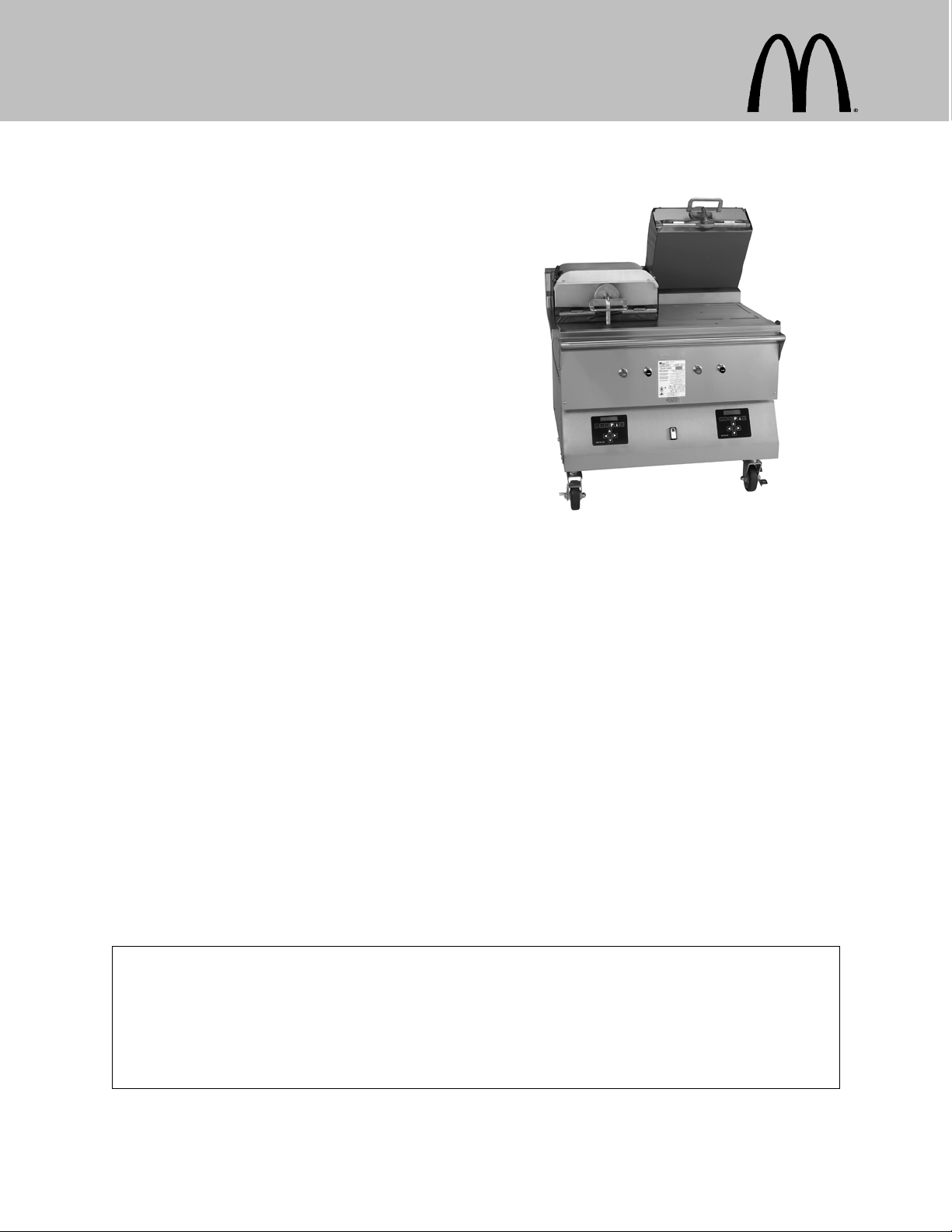
Clamshell Grill
Models C832 & C834
Place this chapter in the Grill section
of the Equipment Manual.
Manufactured exclusively for
McDonald's® by
Taylor Company
750 N. Blackhawk Blvd.
Rockton, IL 61072
McDonald's Hotline:
(877-435-7623)
service@taylor-company.com
Table of Contents
Introduction Page 1.....................................................
Safety Page 1..........................................................
Parts Identification/Function Page 4.......................................
Important to the Operator Page 15.........................................
Equipment Set Up Procedures Page 17.....................................
Menu Screens Page 21...................................................
Daily Cleaning Procedures Page 28........................................
Troubleshooting Guide Page 45............................................
Limited Warranty on Equipment Page 48....................................
Limited Warranty on Parts Page 50.........................................
Ordering/Service Information Page 53......................................
Non-Scheduled Maintenance Page 54......................................
System Set-up Page 54...................................................
Menu Items Page 59.....................................................
Auto Leveling Page 67....................................................
Warranty
Warranty information is contained in this Equipment Manual. Refer to the warranty information listed in the Limited
Warranty on Equipment and Limited Warranty on Parts sections and to the warranty classifications listed in the Parts
Identification/Function section when service is performed on your machine.
It is recommended that the operator take the necessary time to carefully read through the complete warranty information.
Thoroughly understand your warranty protection before you begin operation.
For any questions pertaining to the Taylor Warranty, please contact Taylor Company, Rockton, Illinois 61072.
This manual is for the exclusive use of licensees and employees of McDonald's Corporation.
E2010 McDonald's Corporation
All Rights Reserved
January, 2010 (Original Publication)
(Updated May, 2016)
EM SD11
The United States of America
Printed in
Page 2
INTRODUCTION
The Models C832 and C834 have two
independent upper platens. These grills
provide automatic leveling of the platens.
The grills are capable of cooking a variety of
products and feature two cooking options,
AUTO and MANUAL.
AUTO Option: The grills automatically detect
the product placed on the grill plate (menu
items that are cooked using the upper platen,
only) and set the appropriate cooking
parameters.
MANUAL Option: After the operator selects
the desired product to be cooked, the grills
automatically set the appropriate cooking
parameters.
These grills provide all the features of a flat
grill, as well as the advantages of two-sided
cooking.
All repairs must be performed by an
authorized Taylor service agent. The main
power supplies to the grill must be
disconnected prior to performing any repairs.
These grills are designed for indoor use
only.
Note: Only instructions originating from the
factory or its authorized translation
representative(s) are considered to be the
original set of instructions.
This appliance is to be used only by
trained personnel. It is not intended for use by
children or people with reduced physical,
sensory, or mental capabilities, or lack of
experience and knowledge, unless given
supervision or instruction concerning the use
of the appliance by a person responsible for
their safety. Children should be supervised to
ensure that they do not play with the
appliance.
DO NOT install the unit in an area
where a water jet could be used. DO NOT use
a water jet to clean or rinse the grill. Failure to
follow this instruction may result in serious
electrical shock. In addition, water may collect
inside the grill and destroy electrical
components and cause injury from hot steam.
DO NOT operate the grill unless it is
properly grounded. Failure to comply may
result in equipment damage or personal injury.
This unit is provided with an equipotential
grounding lug that is to be properly attached to
the rear of the frame by the authorized
installer. The installation location is marked by
the equipotential bonding symbol (5021 of IEC
604171) on both the removable panel and the
equipment's frame.
SAFETY
Always follow these safety precautions when
operating the grill:
DO NOT operate the grill without
reading this operator's manual. Failure to
comply may result in equipment damage or
personal injury. This manual should be kept in
a safe place for future reference.
S DO NOT operate the unit unless it is
properly grounded.
S DO NOT operate the unit with larger
fuses than specified on the data label.
S All repairs must be performed by an
authorized Taylor service technician.
S The main power supplies to the
machine must be disconnected prior to
performing any repairs.
S For Cord Connected Units: Only Taylor
authorized service technicians or
licensed electricians may install a plug
or replacement cord on these units.
130826
1
Page 3
S Stationary appliances which are not
equipped with a power cord and a plug
or other device to disconnect the
appliance from the power source must
have an all-pole disconnecting device
with a contact gap of at least 3 mm
installed in the external installation.
S Appliances that are permanently
connected to fixed wiring and for which
leakage currents may exceed 10 mA,
particularly when disconnected or not
used for long periods, or during initial
installation, shall have protective
devices such as a GFI, to protect
against the leakage of current, installed
by the authorized personnel to the
local codes.
S Supply cords used with this unit shall
be oilresistant, sheathed flexible cable
not lighter than ordinary
polychloroprene or other equivalent
synthetic elastomersheathed cord
(Code designation 60245 IEC 57)
installed with the proper cord
anchorage to relieve conductors from
strain, including twisting, at the
terminals and protect the insulation of
the conductors from abrasion.
If the supply cord is damaged, it must
be replaced by an authorized Taylor
service technician in order to avoid a
hazard.
Failure to follow these instructions may result
in personal injury, equipment damage, or poor
grill performance.
WARNING: Improper installation, adjust
ment, alteration, service or maintenance
can cause property damage, injury or
death. Read the installation, operating
and maintenance instructions thoroughly
before installing or servicing this equip
ment.
S This appliance must be isolated from
all combustible construction and
materials including, but not limited to;
walls, partitions, furniture, floors,
curtains, paper, boxes, and
decorations. Failure to comply may
result in fire and cause destruction and
severe injury.
FOR YOUR SAFETY
Do not store or use gasoline or other
flammable vapors or liquids in the vicinity
of this or any other appliance.
S DO NOT obstruct the ventilation
openings at the rear of this appliance.
S DO NOT obstruct the flow of air in and
around the grill.
S DO NOT operate the grill unless all
service panels and access doors are
attached with screws. Failure to comply
may result in personal injury from gas
or electrical components.
USE EXTREME CAUTION while
setting up, operating, and cleaning the grill.
Avoid coming in contact with the hot grill
surfaces or with the hot grease. Failure to
comply will result in burn injuries.
2
130826
Page 4

S The grill must be placed on a level
surface.
S To ensure thorough cleaning, the grill
must be pulled away from the wall.
When returning the grill to its original
position, use extreme caution to
smoothly and slowly roll the grill
backward into place.
Failure to follow these instructions may cause
the grill to tip and can result in severe
equipment damage or personal injury.
NOISE LEVEL: Airborne noise emission does
not exceed 70 dB(A) when measured at a
distance of 1.0 meter from the surface of the
machine and at a height of 1.6 meters from
the floor.
These instructions are valid only if the country
code symbol appears on the appliance. If the
symbol does not appear on the appliance,
refer to the technical instructions which give
the necessary instructions for adapting the
appliance to the utilization conditions of that
country.
NOTICE all warning labels that have
been attached to the grill to further point out
safety precautions to the operator.
HAZARD COMMUNICATION STANDARD
(HCS) - The procedure(s) in this manual
include the use of chemical products.
These chemical products will be
highlighted with bold faced letters followed
by the abbreviation (HCS) in the text
portion of the procedure. See the Hazard
Communication Standard (HCS) manual for
the appropriate Material Safety Data
Sheet(s) (MSDS).
This piece of equipment is made in America
and has American sizes on hardware. All
metric conversions are approximate and vary
in size.
If the crossed out wheeled bin symbol
is affixed to this product, it signifies that this
product is compliant with the EU Directive as
well as other similar legislation in effect after
August 13, 2005. Therefore, it must be
collected separately after its use is completed,
and cannot be disposed as unsorted municipal
waste.
The user is responsible for returning the
product to the appropriate collection facility, as
specified by your local code.
For additional information regarding applicable
local laws, please contact the municipal facility
and/or local distributor.
3
Page 5
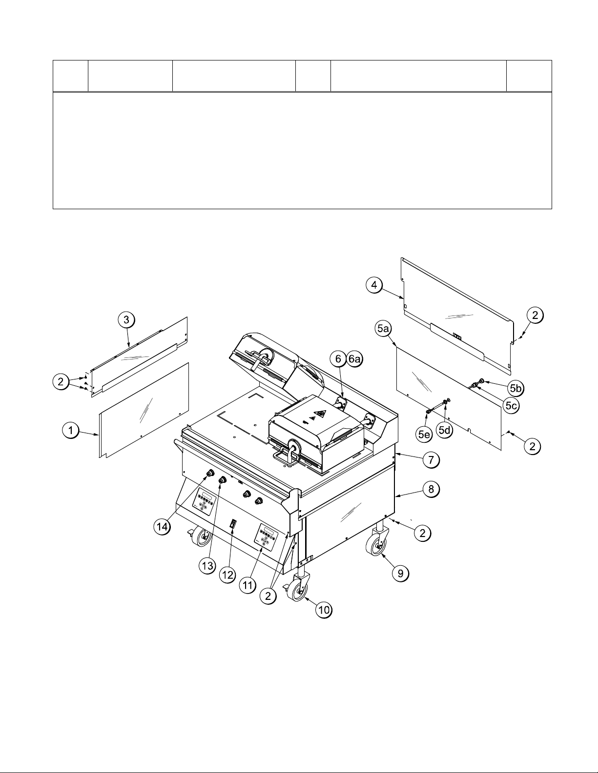
PARTS IDENTIFICATION/FUNCTION
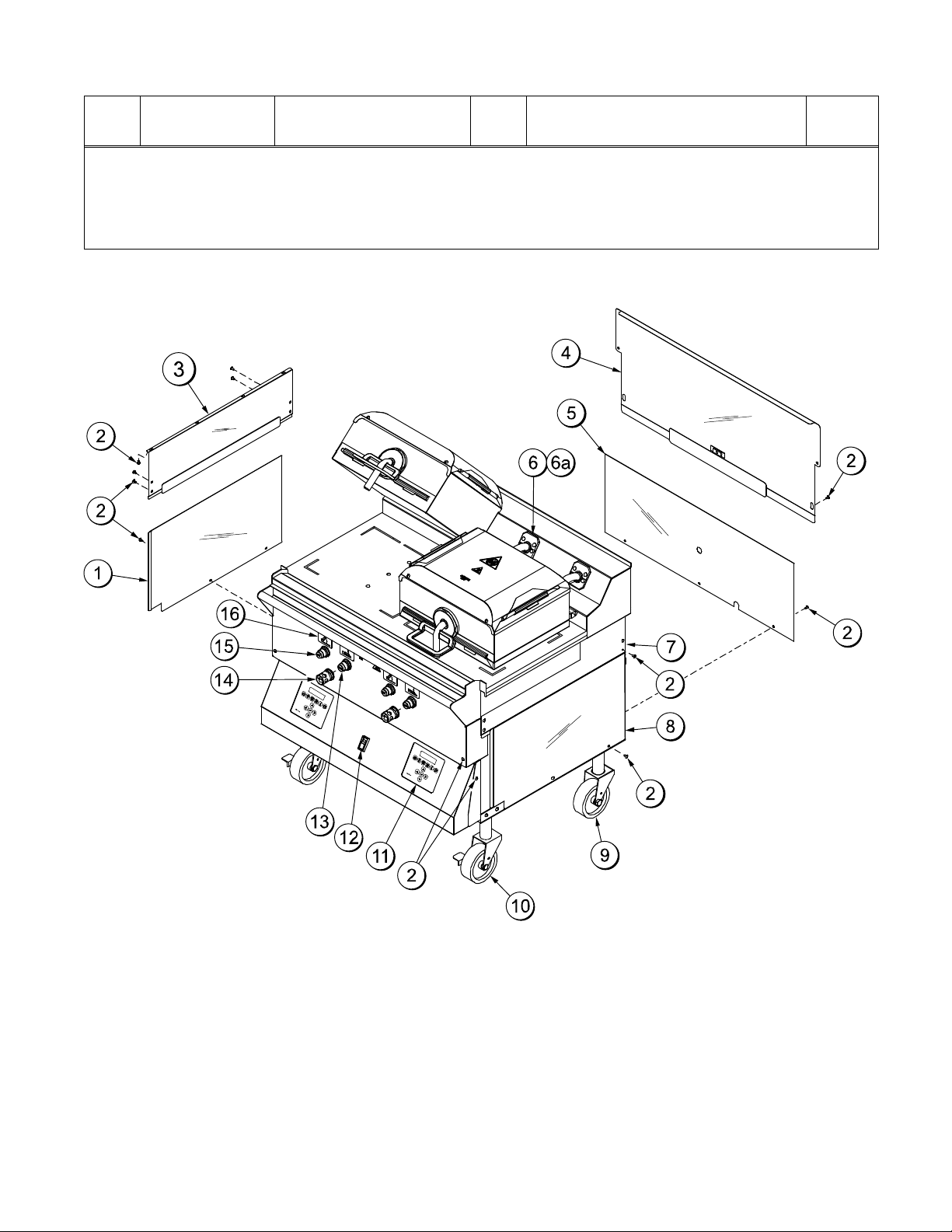
C832 Exploded View (See Figure 1.)
ITEM
PART NO. DESCRIPTION QTY. FUNCTION WARR.
CLASS
1 072967 Panel-Side Left 1 Provides access to internal com
ponents for service and cleaning.
2 024298 Screw-10-32 X 3/8 23 Secures the panel to the frame. 000
3 X72962 Panel A.Side Left
(Upper)
4 X72951 Panel A.Back Service
(Upper)
5 X72958-SER
(Includes
Panel A.Back Panel
(Lower)
5a-5e)
1 Provides access to internal com
ponents for service and cleaning.
1 Provides access to internal com
ponents for service and cleaning.
1 Provides access to internal com
ponents for service and cleaning.
Has a two speed fan connector
built into the panel.
5a 072959 Panel-Back Two Speed
Fan
1 Provides access to internal com
ponents. Has a two speed fan
connector built into the panel.
5b 053889 Cap-Protective Plastic
7/8 THD
1 Protects the plug on the end of
the back panel harness.
5c X74158 Harness A.-Back Pnl 1 Connects to the internal harness
in the grill for the 2 speed fan.
5d 078327 Nut-Locking Conduit
1/2”
1 Secures the back panel harness
connector to the panel.
5e 044823 Connector-Mate Lock 1 Connects the back panel harness
to the internal wire harness.
6 X78330SER Kit A.Grease Shield 2 Prevents grease migration. 103
6a 078329 Fastener-Snap 16 Fastens grease shields to rear
shroud of grill.
7 X72965 Panel A.Side Right
(Upper)
8 072968 PanelSide Right
(Lower)
1 Provides access to internal com
ponents for service and cleaning.
1 Provides access to internal com
ponents for service and cleaning.
9 078377 Caster5” 75/8 Stem 2 Allows grill mobility. 103
10 073240 CasterGrill 5” Swivel
2 Prevents grill movement. 103
w/Lock
11 X72491SER ControlDisplay 2 Controls all functions of the grill. 103
12 076989WP SwitchRockerDPST
10A (Fan Interlock)
1 Activates power to the grill and the
exhaust fans.
103
103
103
103
103
000
103
000
103
000
103
103
103
4
100804
Page 6
C832 Exploded View
ITEM
PART NO. DESCRIPTION QTY. FUNCTION WARR.
13 076012 ButtonOperatorBlack
(Standby)
14 076011 ButtonOperatorRed
(Raise)
2 Activates the cook cycle, keeps
the upper platen in the closed po
sition, and displays the message
“STANDBY” on the control. When
pressed twice within five seconds,
the upper platen will automatically
lower into the Standby position.
2 Cancels the Standby mode, raises
the upper platen, and deactivates
the Cook cycle.
CLASS
000
000
Figure 1
5
101018
Page 7
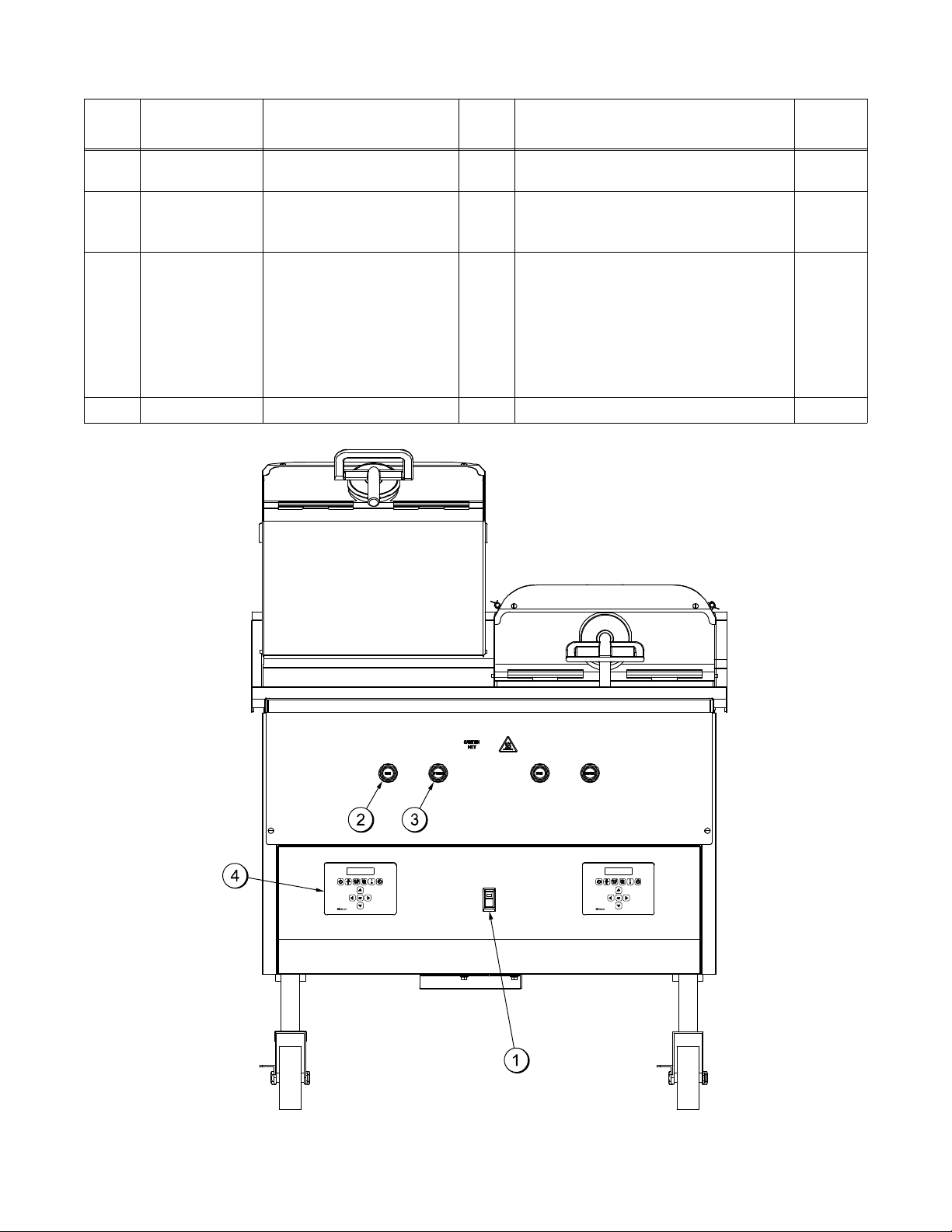
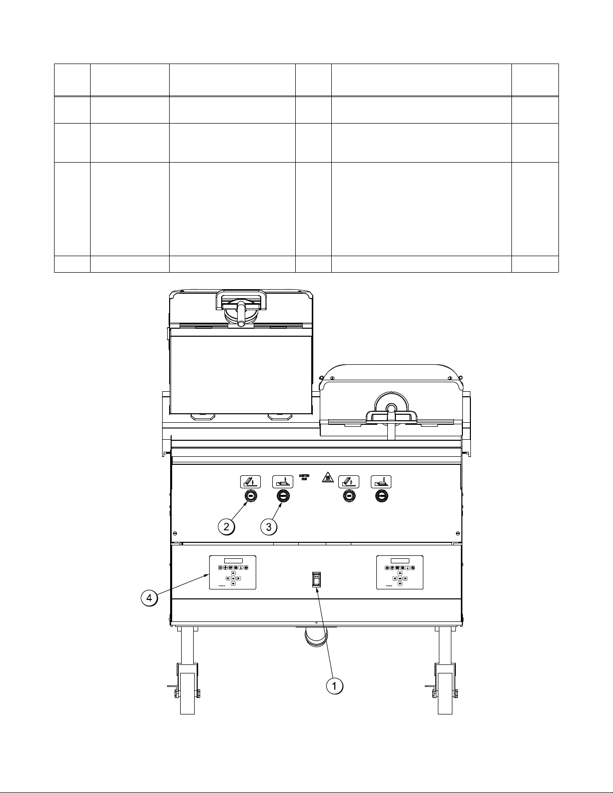
C832 Front View
ITEM
1 076989-WP Switch-Rocker-DPST
2 076011 Button-Operator-Red
PART NO. DESCRIPTION QTY. FUNCTION WARR.
1 Activates power to the grill and the
10A (Fan Interlock)
exhaust fans.
2 Cancels the Standby mode, raises
(Raise)
the upper platen, and deactivates
the Cook cycle.
3 076012 Button-Operator-Black
(Standby)
2 Activates the cook cycle, keeps
the upper platen in the closed
position, and displays the
message “STANDBY” on the
control. When pressed twice
within five seconds, the upper
platen will automatically lower into
the Standby position.
4 X72491-SER Control-Display 2 Controls all functions of the grill. 103
CLASS
103
000
000
Figure 2
6
101018
Page 8
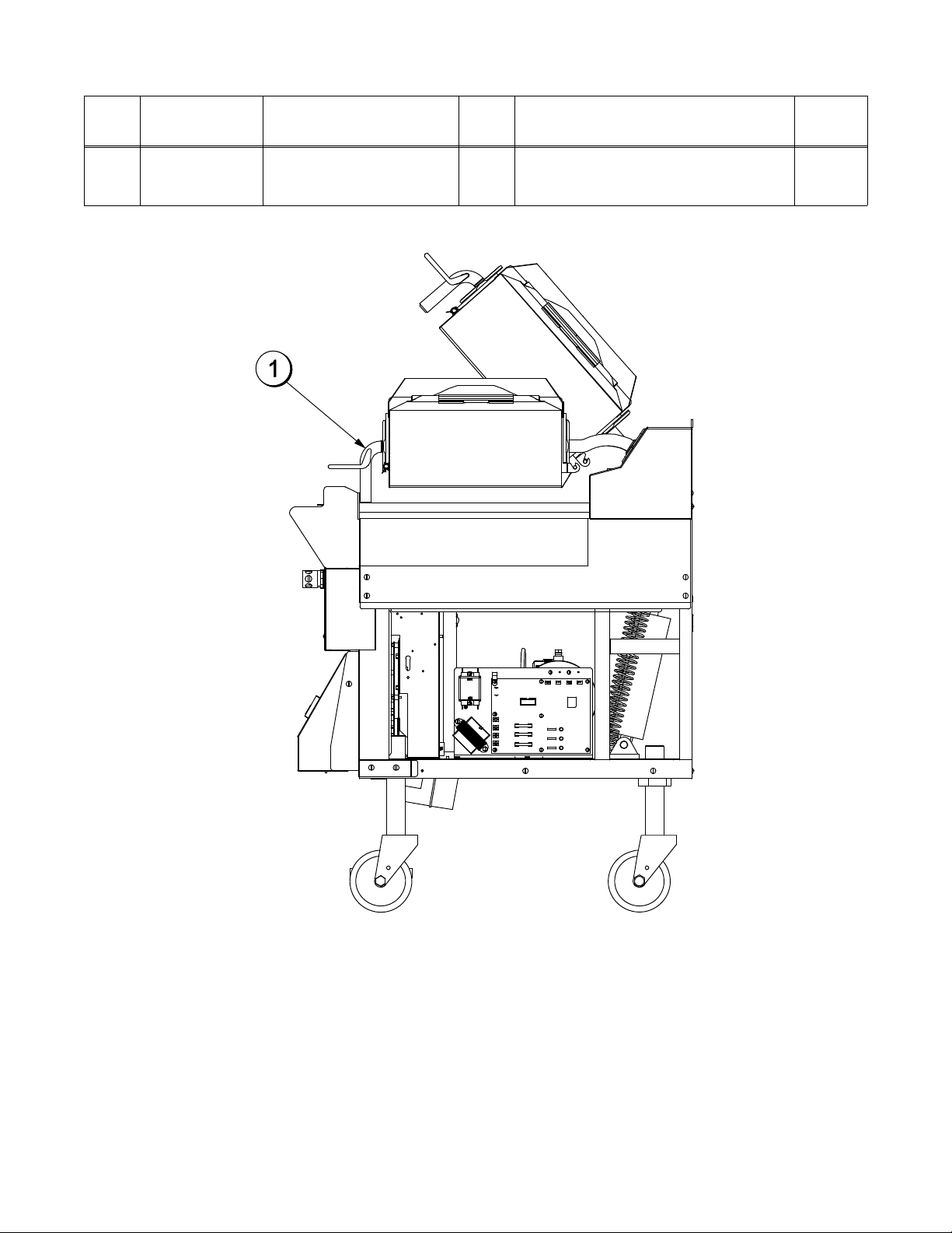
C832 Right Side View
ITEM
PART NO. DESCRIPTION QTY. FUNCTION WARR.
1 072472 Handle-Platen 2 The handle sits solidly on the
lower cook surface when the
platen is lowered.
CLASS
103
Figure 3
7
Page 9
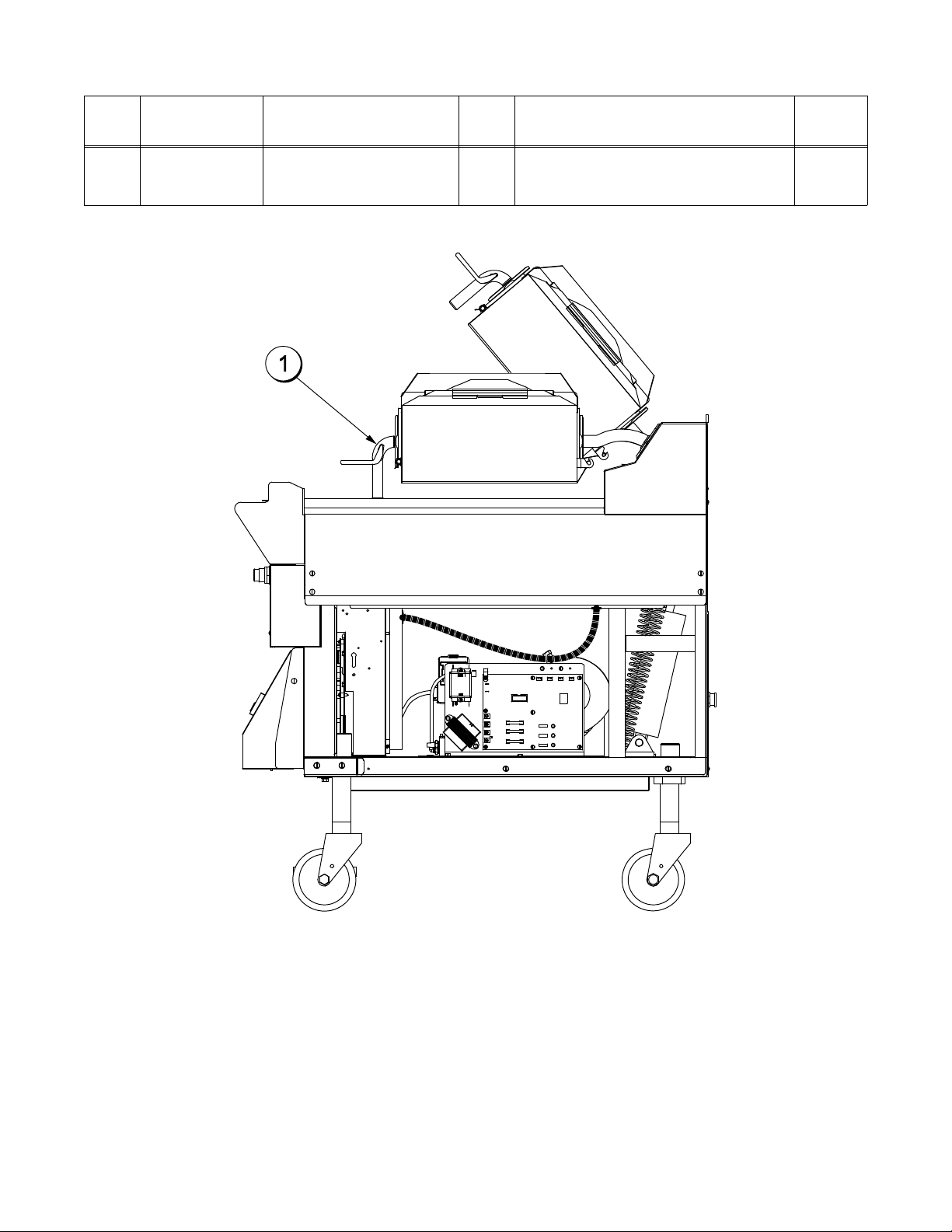
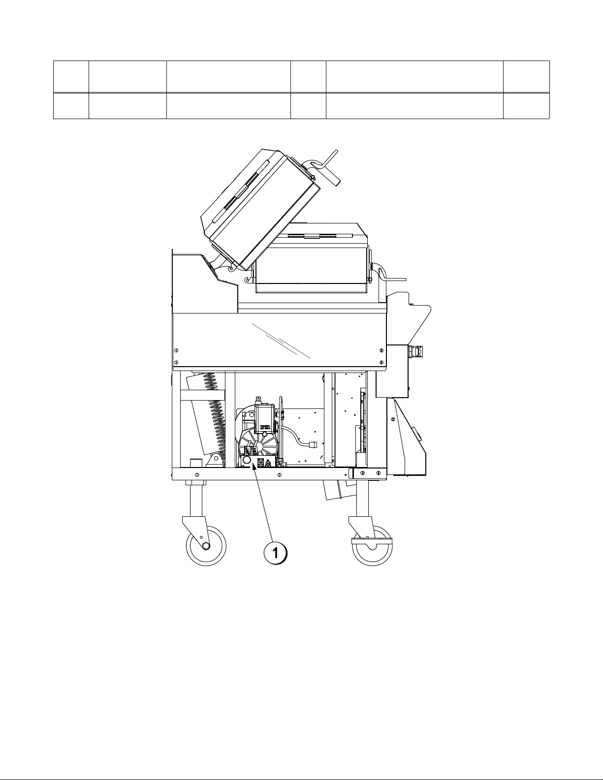
C832 Left Side View
ITEM
PART NO. DESCRIPTION QTY. FUNCTION WARR.
1 073129 Manifold A. 1 Regulates air pressure for platen
operation.
CLASS
103
Figure 4
8
Page 10

C834 Exploded View (See Figure 5.)
ITEM
PART NO. DESCRIPTION QTY. FUNCTION WARR.
CLASS
1 074110 Panel-Side Left
(Lower)
1 Provides access to internal com
ponents for service and cleaning.
2 024298 Screw-10-32 X 3/8 23 Secures the panel to the frame. 000
3 X74126 Panel A.Side Left
(Upper)
4 X72951 Panel A.Back Service
(Upper)
5 072959 Panel-Back Two Speed
Fan
1 Provides access to internal com
ponents for service and cleaning.
1 Provides access to internal com
ponents for service and cleaning.
1 Provides access to internal com
ponents. Has a two speed fan
connector built into the panel.
6 X78330SER Kit A.Grease Shield 2 Prevents grease migration. 103
6a 078329 Fastener-Snap 16 Fastens grease shields to rear
shroud of grill.
7 X74127 Panel A.Side Right
(Upper)
8 074111 PanelSide Right
(Lower)
1 Provides access to internal com
ponents for service and cleaning.
1 Provides access to internal com
ponents for service and cleaning.
9 078377 Caster5” 75/8 Stem 2 Allows grill mobility. 103
10 073240 Caster5” 75/8 Stem
2 Prevents grill movement. 103
Locking
11 X72491SER ControlDisplay 2 Controls all functions of the grill. 103
12 076989WP SwitchRockerDPST
10A (Fan Interlock)
13 076012 ButtonOperatorBlack
(Standby)
1 Activates power to the grill and the
exhaust fans.
2 Activates the cook cycle, keeps
the upper platen in the closed po
sition, and displays the message
“STANDBY” on the control. When
pressed twice within five seconds,
the upper platen will automatically
lower into the Standby position.
14 075288 GuardLens 2 Prevents accidental activation of
the Standby Button.
103
103
103
103
000
103
103
103
000
103
9
100804
Page 11
C834 Exploded View
ITEM
PART NO. DESCRIPTION QTY. FUNCTION WARR.
15 076011 ButtonOperatorRed
(Raise)
16 075699SYM LabelControl Panel
International Symbols
2 Cancels the Standby mode, raises
the upper platen, and deactivates
the Cook cycle.
1
Visually describes the grill platen
Set
functions for standard operation.
CLASS
000
000
Figure 5
10
101018
Page 12
C834 Front View
ITEM
1 076989-WP Switch-Rocker-DPST
2 076011 Button-Operator-Red
PART NO. DESCRIPTION QTY. FUNCTION WARR.
1 Activates power to the grill and the
10A (Fan Interlock)
exhaust fans.
2 Cancels the Standby mode, raises
(Raise)
the upper platen, and deactivates
the Cook cycle.
3 076012 Button-Operator-Black
(Standby)
2 Activates the cook cycle, keeps
the upper platen in the closed
position, and displays the
message “STANDBY” on the
control. When pressed twice
within five seconds, the upper
platen will automatically lower into
the Standby position.
4 X72491-SER Control-Display 2 Controls all functions of the grill. 103
CLASS
103
000
000
Figure 6
11
101018
Page 13
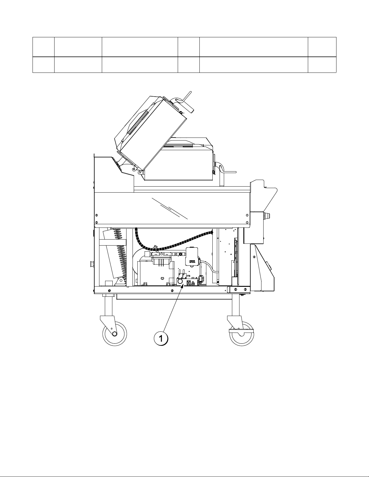
C834 Right Side View
ITEM
PART NO. DESCRIPTION QTY. FUNCTION WARR.
1 072472 Handle-Platen 2 The handle sits solidly on the
lower cook surface when the
platen is lowered.
CLASS
103
Figure 7
12
Page 14
C834 Left Side View
ITEM
PART NO. DESCRIPTION QTY. FUNCTION WARR.
1 073129 Manifold A. 1 Regulates air pressure for platen
operation.
CLASS
103
Figure 8
13
Page 15
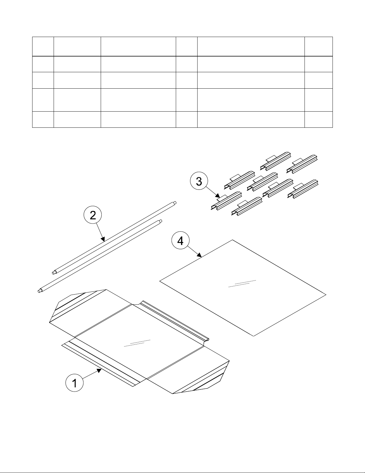
Accessories
ITEM
1 073317 Sheet-Release
PART NO. DESCRIPTION QTY. FUNCTION WARR.
1 Non-stick barrier used to protect
(Box of 6)
the upper platen.
2 076155 Rod-Release Material 2 Slides through the loop in the
release material sheet.
3 072673 Clip-Release Material
w/Tab
8 Secures the non-hemmed end of
the release sheet to the release
material bar.
*4 081432 Sheet-Lower Release
(Box of 12)
1 Non-stick barrier used to protect
the lower cook surface.
*For grill markets using lower release sheet, only.
CLASS
000
103
000
000
Figure 9
14
121102
Page 16

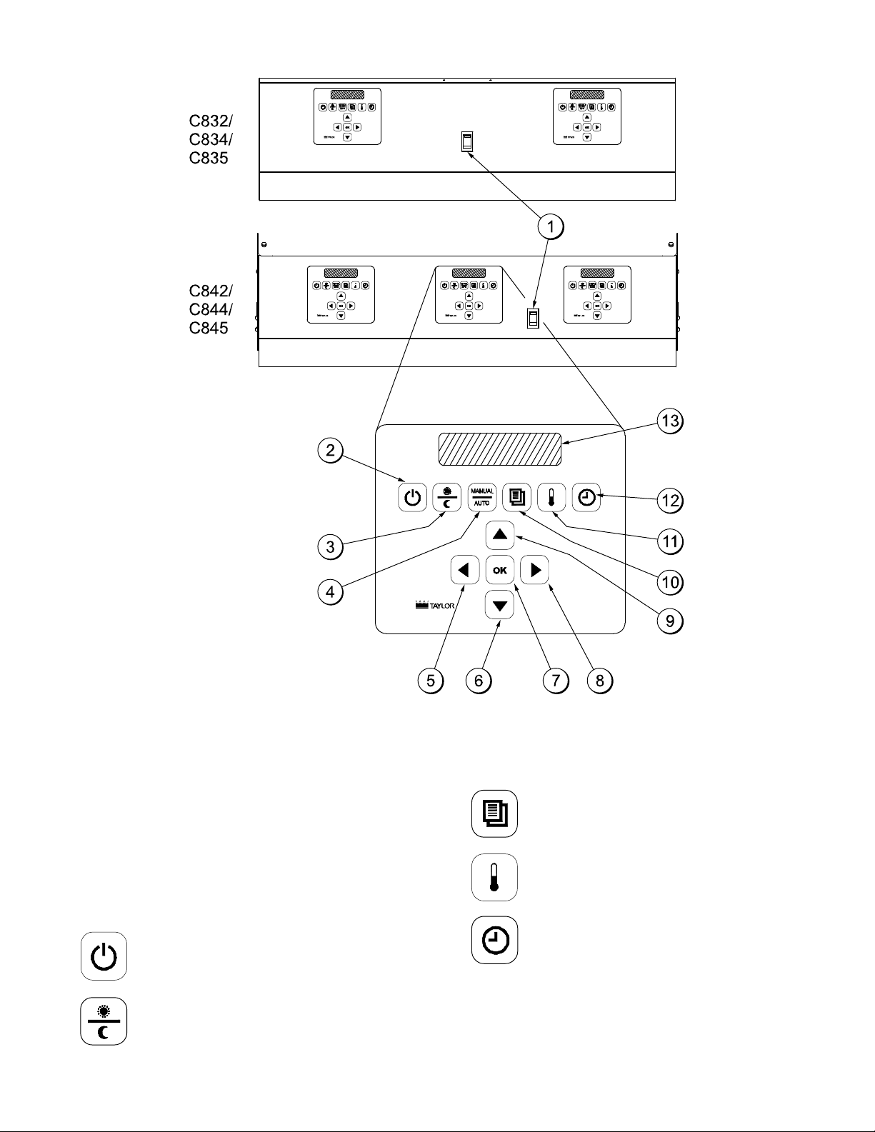
IMPORTANT TO THE OPERATOR
Important to the Operator Exploded View (See Figure 10.)
ITEM DESCRIPTION FUNCTION
1 Fan Interlock Switch This switch activates power to the grill and the exhaust fans.
2 ON/OFF Key This key is used to turn the controller on and off to start a
preheating mode and to auto-gap the platen. The key must be
pressed and held for three seconds to activate, in order to
prevent unintended operation.
3 AM/PM Key This key is used to toggle back and forth between the AM and PM
menu item lists.
4 MANUAL/AUTO Key This key is used to toggle back and forth between the Manual
and Auto modes.
5 Left Arrow Key This key is used to scroll through menu items when cooking in the
Manual mode. (Inactive in the Auto mode.)
6 Down Arrow Key While in the Menu mode, this key is used to decrease a numerical
value and to scroll through the characters when entering a new
menu item or modifying an old one. (Inactive in the Auto mode.)
7 OK Key This key is used to accept the information entered.
8 Right Arrow Key This key is used to scroll through menu items when cooking in the
Manual mode. (Inactive in the Auto mode.)
9 Up Arrow Key While in the Menu mode, this key is used to increase a numerical
value and to scroll through the characters when entering a new
menu item or modifying an old one. (Inactive in the Auto mode.)
10 Program Key This key is used to enter and exit the Programming mode.
11 Temperature Key When pressed and held for 3 seconds, this key will access the
Probe Calibration screen.
12 Cook Time Key This key is used to change the remove time of a specific menu
item. To change a specific cook time, the item must be selected in
the Manual mode. (Note: Press and hold the Cook Time key for
three seconds to activate.)
13 Liquid Crystal Display This screen displays menu options and information.
15
101018
Page 17
Important to the Operator
Symbol Definitions
To better communicate in the International
arena, the words on many of our operator
keys have been replaced by symbols to
indicate their functions. Your Taylor equipment
is designed with these International symbols.
The following chart identifies the symbol
definitions.
= ON/OFF
= AM/PM
Figure 10
= PROGRAM
= TEMPERATURE
= TIME
101018
16
Page 18
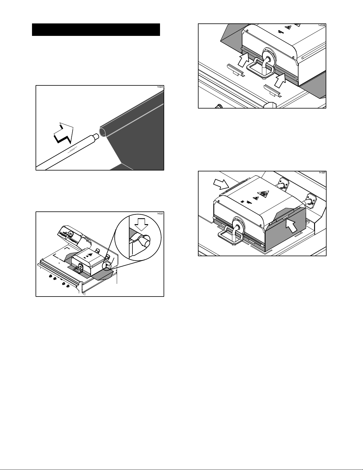
EQUIPMENT SET-UP PROCEDURES
Installing Upper Platen Release Sheets
1. Slide the release material retention bar
through the loop in the release sheet.
(See Figure 11.)
Figure 11
2. Engage the material retention bar into the
hooks provided on the platen.
(See Figure 12.)
Figure 13
4. Carefully wrap the release sheet side
flaps over the cover rails and secure the
sheet with locking clips. (See Figure 14.)
Figure 12
3. Center the release sheet on the bar. Pull
it tightly over the release material bar
located in the front of the platen. Secure
the sheet with two locking clips.
(See Figure 13.)
Figure 14
IMPORTANT! Do not crease the release
sheet. This will greatly reduce the life
of the sheet.
5. Make sure the release sheets are tight
across the upper platen surface.
6. Repeat these steps for the other upper
platen.
17
Page 19
Installing Lower Release Sheets
(Grills Using Lower Release Sheets)
Note: The following steps pertain to grill
markets using lower release sheets, only. If
lower release sheets are not used, proceed to
“Start-Up of the Grill” on page 20.
WARNING! Upper release sheets
cannot be used on the lower grill surface. Poor
quality and potential food safety issues will
occur.
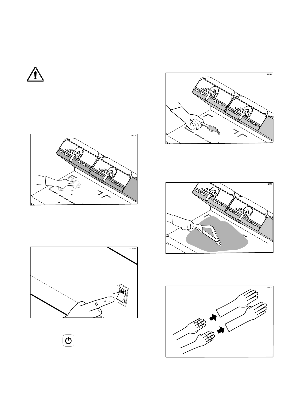
1. Clean the grill with a sanitizer-soaked grill
cloth to remove any debris on the grill.
(See Figure 15.)
4. The screen will then display, “CLEAN
GRILL SURFACES,” followed by “CLOSE
PLATEN FOR AUTO LEVELING.”
5. Using a sundae spoon, distribute two level
spoonfuls of soy adhesion flakes over a
warm 3 ft. (1 m.) grill surface, allowing the
flakes to melt. (See Figure 17.)
Figure 17
6. Using a clean squeegee, spread the
flakes on the cooking zone.
(See Figure 18.)
Figure 15
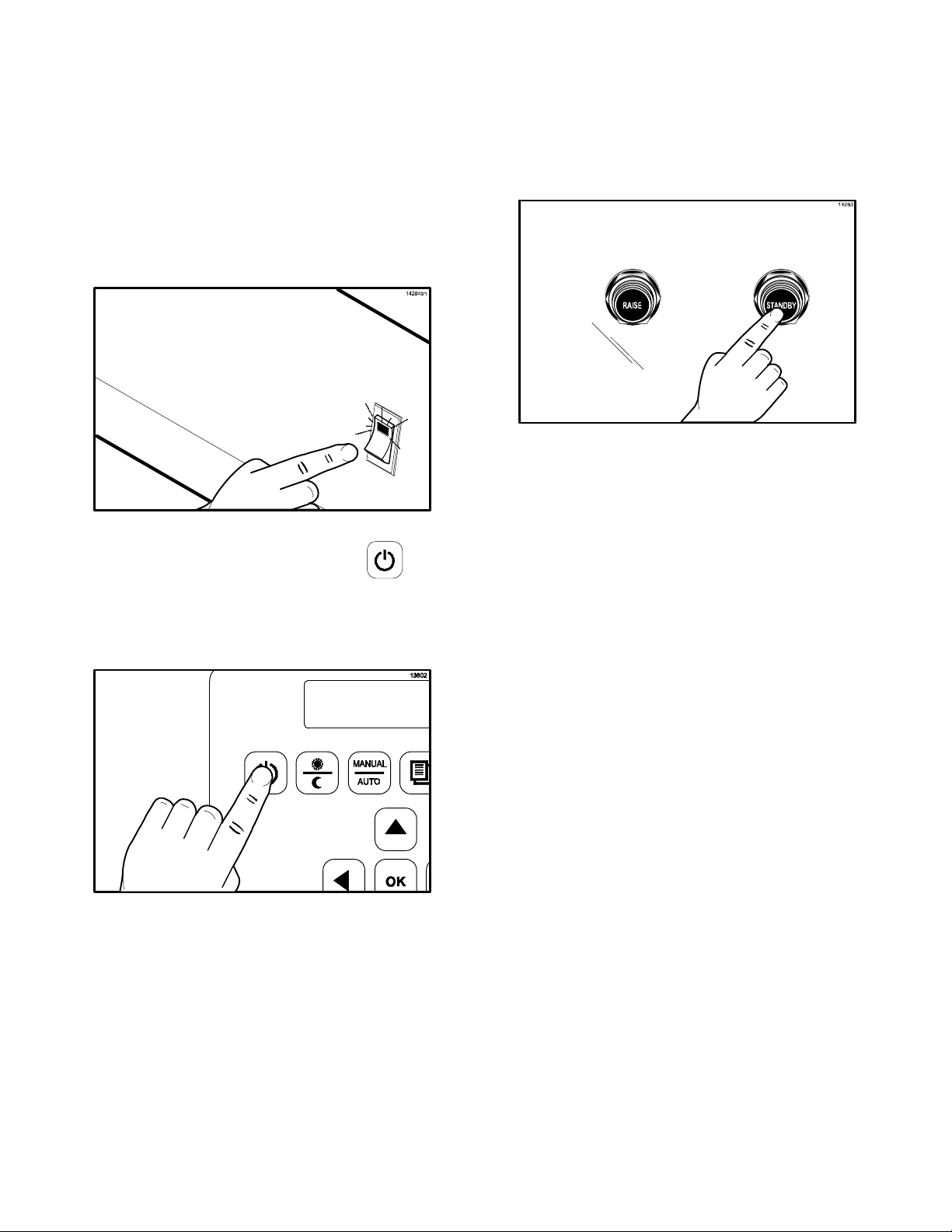
2. Place the fan interlock switch in the ON
position. The controller will display the
message “OFF”. (See Figure 16.)
Figure 16
3. Press the key for 3 - 5 seconds. “AM
TOO COOL” and “AM FOLDED EGGS CLAM” will be displayed on the control
screen.
Figure 18
7. Put on heat-resistant gloves.
(See Figure 19.)
Figure 19
18
121102
Page 20
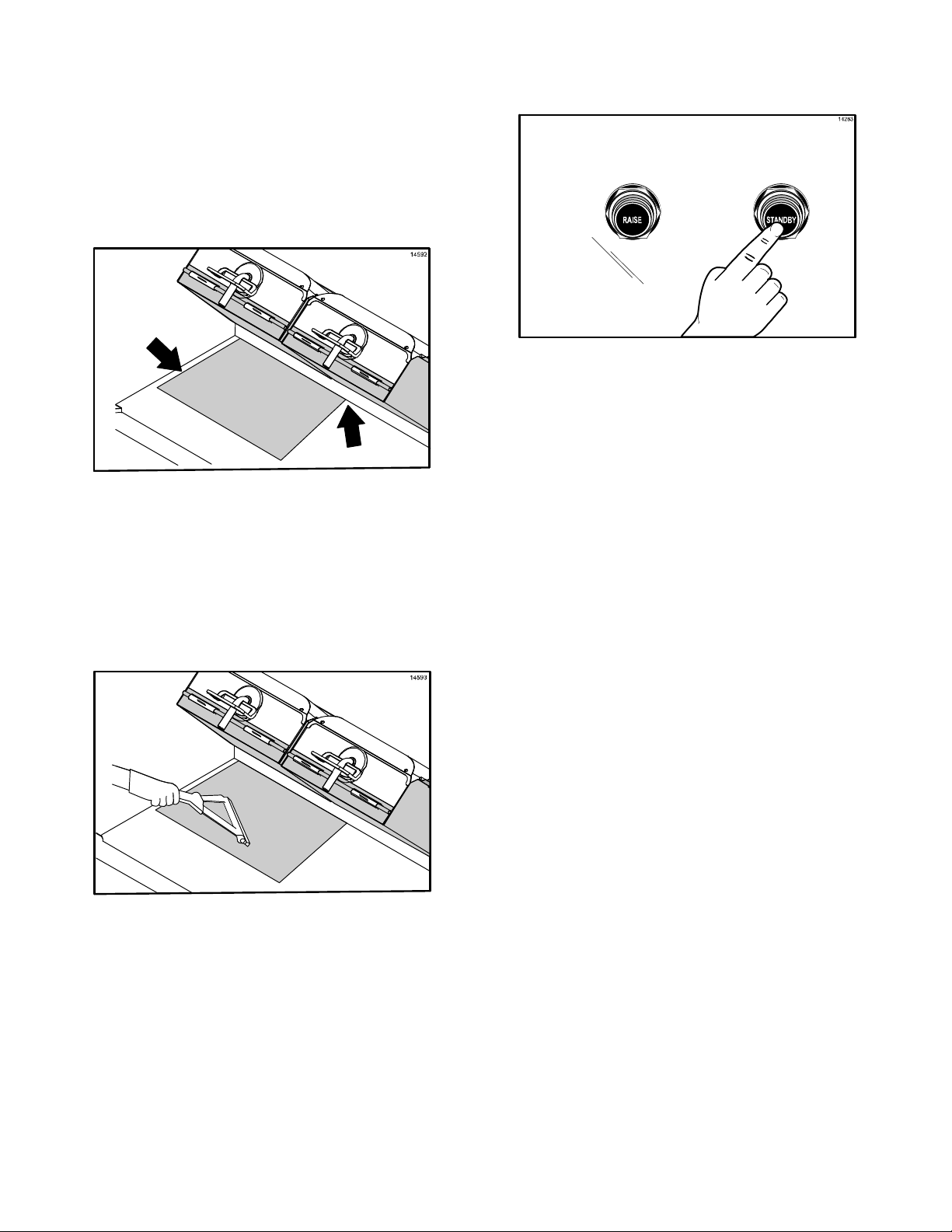
8. With the longest side of the lower release
sheet facing the back of the grill, hold the
release sheet about one inch from the
end of each side. Align the back edge of
the release sheet with the back splash
and the side edge of the grill.
(See Figure 20.)
11. Press the Standby button to close the
platen. (See Figure 22.)
Figure 22
12. After the platen has closed, the grill will
start heating up to the proper
temperature. The control will display the
following message until the grill has
reached the proper temperature, ”TOO
COOL FOR AUTO LEVELING”.
Figure 20
9. Using the grill squeegee, gently squeegee
out air bubbles, making sure not to crease
or fold the release sheet. (See Figure 21.)
Figure 21
13. When the grill has reached the proper
temperature, the screen will display,
“PLEASE WAIT FOR AUTO LEVELING”.
14. When the Auto Leveling is complete, the
upper platen will raise. The screen will
display the product that had been
selected.
The release sheet must be changed when:
S Product sticks to the release sheet.
S Carbon builds up, causing problems in
taste or appearance.
S There is a tear in the release sheet in
the cooking area.
S The release material substance is worn
from the release sheet.
Note: Reverse the cooking side of the release
sheets on a daily basis.
10. Repeat the last 2 steps for the other
half of the grill surface. The release
sheets will overlap about 1” (25 mm) in
the middle.
Note: When properly applied, the release
sheet will lay flat, with only a few small air
bubbles.
Care of Release Sheets
S DO NOT fold or crease.
S DO NOT touch with any sharp object or
abrasive.
S DO NOT hose with hot water or soak in
water.
S DO NOT place under other objects.
121101
19
Page 21
Start-Up of the Grill
IMPORTANT: The lower grill plate and the
upper platen MUST BE CLEAN before starting
these procedures.
Note: Grills that use lower release sheets
require start up of grill before installation of
lower release sheets. (See page 18.)
1. Place the fan interlock switch in the ON
position. The controller will display the
message “OFF”. (See Figure 23.)
Figure 23
2. Heat up the grill by pressing the key
for 3 - 5 seconds. “AM TOO COOL” and
“AM FOLDED EGGS - CLAM” will be
displayed on the control screen.
(See Figure 24.)
3. The control will first display, “CLEAN
GRILL SURFACES” and then display,
“CLOSE PLATEN FOR AUTO
LEVELING.”
4. Press the Standby button to close the
platen. (See Figure 25.)
Figure 25
5. After the platen has closed, the grill will
start heating up to the proper
temperature. The control will display the
following message until the grill has
reached the proper temperature, ”TOO
COOL FOR AUTO LEVELING”.
6. When the grill has reached the proper
temperature, the screen will display,
“PLEASE WAIT FOR AUTO LEVELING”.
7. When the Auto Leveling is complete, the
upper platen will raise. The screen will
display the product that had been
selected.
Figure 24
20
Page 22

MENU SCREENS
Manager Menu - Passcode Access
Limited access to menu screens is available
through the Operator Menu or the Manager
Menu. In order to enter the Operator Menu or
the Manager Menu, individual passcodes must
be entered.
Operator Menu - Passcode Access
The Operator Menu gives limited MENU and
SYSTEM SETUP access. Access to this menu
is intended for day to day operations
(whomever is responsible for Beef Integrity).
To enter the Operator Menu, press the
key to display “PROGRAMMING.” Press the
key to display the passcode entry
screen. Enter the Operator Menu passcode by
pressing the keys in this order:
The Manager Menu gives access to all MENU
items and limited SYSTEM SETUP access. To
access the Manager Menu, press the
key to display “PROGRAMMING.” Press the
key to display the passcode entry
screen. Enter the Manager Menu passcode by
pressing the keys in this order:
All MENU items will be visible, including “ADD
ITEM”. All parameters are available for each
menu item.
S REMOVE IN GAP
S STAGE 1 TIME
All menu items will be visible, except “ADD
ITEM”. The following parameters are available
for each menu item:
S AM/PM
S REMOVE IN
S REMOVE ALARM
S MUST REMOVE IN
S PREP BREAD IN
S PREP ALARM
The following SYSTEM SETUP parameters
will be available:
S PROBE CALIBRATION
S TEMPERATURE DISPLAY
S AUTO CLOSE
S SPEAKER VOLUME
S STATE 1 GAP
S TOP TEMPERATURE
S BOTTOM TEMPERATURE
S AUTO SELECTION
S AUTO GAP
The following SYSTEM SETUP parameters
will be available, in addition to those available
in the Operator Menu.
S AUTO PROD MELT TIME
S GATEWAY ENABLE
S DATE
S TIME
S 24 HOUR STORE
S AUTO IDLE TOP TEMP
S AUTO IDLE BOTTOM TEMP
S TOO COOL DELAY
S STANDBY ALERT
140908
21
Page 23

Product Selection
The
key allows the operator to cook in
either the AUTO mode or in the MANUAL
mode.
AUTO Mode
In the AUTO mode, the grill automatically
detects the product that is placed on the lower
grill plate and sets the appropriate cooking
parameters. The AUTO option is only
available for clam items.
Note: In “MENU ITEMS”, the AUTO
SELECTION parameter must be set to
“YES”.
MANUAL Mode
In the MANUAL mode, the operator selects
the desired product to be cooked.
To select a product using the MANUAL item
option, perform the following steps.
Patty Placement
Placement procedures of meat products must
be followed on the grill. Meat must be placed
on the lower grill plate, two patties at a time,
from front to back, per the patty placement
guide on page 23. When the cook cycle is
complete, the upper platen will raise.
The patties must be removed immediately
after the upper platen has been raised to the
OPEN position and the meat has been
seasoned. Remove the patties, one at a time,
from front to back and right to left, per the
patty placement guide on page 23.
The maximum amount of meat patties to be
cooked on each side of the grill is as follows.
S 8 regular (10:1) patties
S 6 quarter pound (4:1) patties
S 4 Angus patties
S 8 sausage patties
S 6 circular bacon
The following chart is to be used as the patty
placement guide.
1. Press the
key. “AM” will be
displayed on the control screen. If “PM” is
desired, press the
key one more
time.
2. Use the
or keys to scroll
through the various product menu
selections. Continue this process until the
desired product is displayed. The product
that is displayed will be selected.
22
Page 24

Models C832 & C834
IntelliGapt Grill
10:1, 4:1, Sausage, Circular Bacon, and
Patty Placement Guide
Figure 26
Note: Patty placement procedures for International Markets may differ. Follow the recommendations
of your local McDonald's authorities.
23
121221
Page 25

Standby Procedures
Whenever the grill is idle and product is not
being cooked, the upper platen must be
placed in the STANDBY position.
1. To place the upper platen in the
STANDBY position, press the STANDBY
button twice from the open position.
(See Figure 27.)
Cleaning After Each Run of Product
(Grills Using Lower Release Sheets)
Note: This manual contains separate
procedures for grills that use lower release
sheets and for grills that do not use lower
release sheets. Use the appropriate
procedures for your grill.
If your grill does not
use lower release
sheets, go to page 25.
1. Squeegee the lower release sheet from
front to back. (See Figure 29.)
Figure 27
2. To raise the upper platen to the OPEN
position to resume cooking, press the
RAISE button. (See Figure 28.)
Figure 28
Note: If the grill remains idle for 5 continuous
minutes without being placed in STANDBY, a
tone will sound and the display will flash “PUT
GRILL IN STANDBY”.
Figure 29
2. Squeegee the upper release sheet from
top to bottom. (See Figure 30.)
Figure 30
CAUTION: NEVER USE FORCE TO
RAISE THE UPPER PLATEN. DAMAGE TO
COMPONENTS WILL RESULT. USE ONLY
THE RAISE BUTTON TO OPEN THE UPPER
PLATEN!
3. Push the residue into the grease trough.
Note: Do not use excessive pressure when
wiping the release sheet with the squeegee.
Using excessive pressure can scratch or tear
the release sheet.
121101
24
Page 26

4. Carefully squeegee the air bubbles from
center to side, making sure the release
sheet does not become folded or creased.
5. Wipe the squeegee with a sanitizersoaked grill cloth.
6. Wipe the top platens and grill surface 4
times an hour with a sanitizer-soaked grill
cloth.
7. As needed during operation, use a
sanitizer-soaked grill cloth to clean the
back splash plate and the bullnose areas.
CAUTION: THE UPPER PLATENS
AND LOWER COOK SURFACE ARE HOT!
TO PREVENT BURN INJURIES, USE
EXTREME CAUTION WHEN WIPING THE
RELEASE MATERIAL SHEETS.
Cleaning After Each Run of Product
(Grills Not
Using Lower Release Sheets)
Note: This manual contains separate
procedures for grills that use lower release
sheets and for grills that do not use lower
release sheets. Use the appropriate
procedures for your grill.
2. Use the wiper squeegee to clean the
release sheet on the upper platen. Use a
diagonal motion to clean the sheet. Hold
the handle at a slight upward angle, with
the wiper end facing downward.
(See Figure 32.)
Figure 32
Note: Do not use excessive pressure when
wiping the release sheet with the squeegee.
Using excessive pressure can scratch or tear
the release sheet.
3. Using the wiper squeegee, push the
grease at the rear of the lower grill plate
into the grease can. Do not use the grill
scraper for this step. (See Figure 33.)
If your grill uses lower release sheets, go to
page 24.
1. Using the grill scraper, scrape the grease
on the lower grill plate from front to back.
Do not scrape across the rear of the
lower grill plate with the grill scraper.
(See Figure 31.)
Figure 31
Figure 33
4. Use the grill cloth to clean the back splash
plate and the bullnose areas, as needed
during operation.
Note: To increase the life of the release
sheet, wipe it with a damp, folded grill cloth a
minimum of four times every hour.
CAUTION: THE UPPER PLATEN
SURFACE IS VERY HOT! TO PREVENT
BURN INJURIES, USE EXTREME CAUTION
WHEN WIPING THE RELEASE MATERIAL
SHEET.
25
121102
Page 27

To Cook in the Flat Grill Mode
1. To select a flat grill menu item, press the
To Transition From Breakfast to Lunch
1. If the grill is in the AM AUTO Mode, press
the
key to select PM.
key.
2. Press the
key for the Manual Mode.
The display may show “TOO COOL” or
“TOO HOT”, until the grill reaches the set
temperatures.
3. Use the
or keys to scroll to the
flat grill menu item.
4. After placing product in the prescribed
method, press the STANDBY button to
start the cook cycle. (See Figure 34.)
2. If the grill is set to a certain breakfast item
in the Manual Mode, press the
key
to select PM.
3. The display may show “TOO COOL” or
“TOO HOT”, until the grill reaches the set
temperatures.
To Display the Current Temperatures
Note: The actual temperatures may be
displayed at any time, including during a cook
cycle.
1. Press the
key. A series of screens
will display. The first screen will display as
follows.
Top Bck (AM/PM) Top Frt
Figure 34
5. Perform the functions that appear on the
display (i.e., sear, turn). Pressing the
RAISE button will cancel the cook cycle.
6. When the cook cycle is complete, the
display will flash the message “REMOVE”
and an audible alert will sound. Remove
the product per the prescribed method.
Back Cntr Frt
2. The next display will show the actual
temperatures, per the following example.
426 Now/Deg F 425
348 350 349
Note: Pressing the key once and the
key five times will keep the temperatures
on the screen until the
key is pressed.
26
Page 28

3. The next display will show the set point
temperatures, per the following example.
425 Set/Deg F 425
350 350 350
4. The display will then return to the selected
menu item.
To Change Product Cook Times
Probe Calibration
For grill markets that use lower release
material sheets, probe calibration is performed
with the release sheets installed. For grill
markets that do not use lower release material
sheets, probe calibration is performed without
the lower release sheets installed.
Thermocouple probes are located from front to
rear on the lower grill plates and upper
platens. Measurements should be taken from
front to back and left to right on all model grills.
See Figures 35 and 36 below, which identify
the probe locations.
Model C832
1. Press the
key to put the grill into the
Manual Mode.
2. Scroll to the menu item that requires a
change to the cook time by pressing the
or keys.
3. Press and hold the
key for 3-5
seconds.
4. Use the
and the
key to increase the time
key to decrease the time.
Each press of the key changes the time
by one second.
Figure 35
Model C834
5. Press the
key to save the changes.
To Change a Menu Item
See “Product Selection” on page 22.
Figure 36
160505
27
Page 29

1. Press the key to put the grill into the
Manual Mode.
2. Press and hold the
key for three
seconds.
3. Place a pyrometer surface probe on the
selected heat zone as shown in
Figures 35 and 36.
4. If the displayed temperature on the
controller is more than 5°F/3°C different
from the pyrometer surface probe display:
Press the
temperature or press the
key to increase the
key to
decrease the temperature to match the
displayed temperatures.
Note: The set of numbers that follow the
zone name represent the previous
calibration adjustment.
DAILY CLEANING PROCEDURES
Grills Using Lower Release Sheets
Note: This manual contains separate
procedures for grills that use lower release
sheets and for grills that do not use lower
release sheets. Use the appropriate
procedures for your grill.
If your grill does not
use lower release
sheets, go to page 36.
S CAUTION: Never use cold water or
ice to cool the upper platen or the
lower grill plate.
S Never use grill screens on the upper
platen or the lower grill plate.
S Never allow the grill scraper or
abrasive cleaning materials to come
in contact with the release sheet.
1. Raise the upper platen to the OPEN
position by pressing the red RAISE key.
(See Figure 37.)
5. To calibrate the next zone, use the
key to move to the next zone.
6. Once calibration is complete, press the
key to save all changes.
Figure 37
CAUTION: NEVER USE FORCE TO
RAISE THE UPPER PLATEN. DAMAGE TO
COMPONENTS MAY RESULT. USE ONLY
THE RAISE KEY TO OPEN THE UPPER
PLATEN!
28
121102
Page 30

2. Press the key until the message
“CLEANING” is displayed
3. Press the
key.
When the cook surfaces reach the proper
temperature for cleaning, an alarm will
sound and the message “READY TO
CLEAN” will be displayed.
4. Press the key to cancel the alarm.
SHEETS ARE VERY HOT. TO PREVENT
BURN INJURIES, USE EXTREME CARE.
8. Wipe the exposed surface of the upper
and lower release sheets with a clean,
sanitizer-soaked grill cloth.
(See Figure 40.)
5. Press the
key again and the
message “OFF” will display.
6. Put on heat-resistant gloves.
(See Figure 38.)
Figure 38
7. Remove, empty, and reinstall the grease
pans. (See Figure 39.)
Figure 40
9. Open one packet of McD Hi-Temp Grill
Cleaner (HTGC). Empty the contents into
a clean entrée base or stainless steel
pan. (See Figure 41.)
Figure 41
10. Dip a clean, sanitizer-soaked grill cloth
into the grill cleaner. Do not saturate the
cloth. (See Figure 42.)
Figure 39
CAUTION: THE UPPER PLATENS,
LOWER COOK SURFACE AND RELEASE
Figure 42
121102
29
Page 31

11. Use the grill cloth dampened with grill
cleaner to clean the exposed surfaces of
the upper and lower release sheets.
(See Figure 43.)
Figure 43
12. Remove the release sheet locking clips,
the bars, and the upper and lower release
sheets. Wash and rinse the clips and bars
in the 3-compartment sink. If necessary,
soak them in a hot solution of SolidSense
APSC to remove carbon accumulation.
(See Figure 44.)
14. Dip the Kay Grill Cleaning Pad Holder into
the grill cleaner. (See Figure 45.)
Figure 45
IMPORTANT: DO NOT scrub while applying
the grill cleaner in the following steps:
15. Spread a light coating of the grill cleaner
over the entire lower grill surface, using
front to back strokes. Allow the product to
remain on the grill while spreading across
all surfaces. (See Figure 46.)
Figure 44
13. Place all release sheets flat on the
release sheet storage tray. DO NOT fold,
crease, or place them on sharp objects.
DO NOT clean them in the 3-compartment
sink.
Figure 46
Note: Allowing the grill cleaner to sit on
the grill surfaces will require less effort
and time to scrub heavy soil buildup and
achieve a clean grill.
121102
30
Page 32

16. Apply McD Hi-Temp Grill Cleaner
(HTGC) to the front side of the platens,
starting from the right platen to the left
platen. (See Figure 47.)
Figure 47
17. Apply the grill cleaner to the platen
surfaces, starting from the right platen to
the left platen. (See Figure 48.)
19. Apply the grill cleaner to the outer edges
of the right and left platens.
(See Figure 50.)
Figure 50
20. Press the black STANDBY button to lower
the right platen.
Figure 48
18. Apply the grill cleaner to the back side of
the platens, from the right platen to the
left platen. (See Figure 49.)
Figure 49
21. Apply grill cleaner to the inner edges of
the right and left platens. (See Figure 51.)
Figure 51
22. Press the red RAISE button to raise the
right platen.
31
Page 33

23. Using the Kay Grill Cleaning Pad Holder,
scrub the front side of the platens from
the right platen to the left platen. (See
Figure 52.)
26. Scrub the outer edges of the right and left
platens. (See Figure 55.)
Figure 55
Figure 52
Note: Scrub all areas containing visible
soil accumulation until the soil liquefies.
24. Scrub the platen surfaces, starting from
the right platen to the left platen.
(See Figure 53.)
Figure 53
25. Scrub the back side of the platens from
the right platen to the left platen.
(See Figure 54.)
27. Press the black STANDBY button to lower
the right platen.
28. Scrub the inner edges of the right and left
platens. (See Figure 56.)
Figure 56
29. Press the red RAISE button to raise the
right platen.
Figure 54
32
Page 34

30. Rinse all areas of the platen surfaces with
a clean, sanitizer-soaked grill cloth,
starting from the right platen to the left
platen. Lower and raise the platens as
needed to gain access to the sides of the
platens. (See Figure 57.)
Figure 57
31. Rinse the lower grill surface with a clean,
sanitizer-soaked grill cloth.
(See Figure 58.)
32. Clean the surrounding areas such as the
hood, bull nose, and back splash, with a
clean, sanitizer-soaked grill cloth.
(See Figure 59.)
Figure 59
Note: The rear of the upper platen, as
well as the tubular arm, can easily be
wiped from the front of the unit. If cleaning
is performed on a daily basis, there
should be no carbon build-up.
33. One at a time, place the upper and lower
release sheets on the lower grill surface.
Wipe both sides of each release sheet
with a clean, sanitizer-soaked grill cloth.
(See Figure 60.)
Figure 58
Figure 60
121102
33
Page 35

34. Re-install the upper release sheets.
Secure the sheets with the locking clips
and bars. (See Figure 61.)
Figure 61
Note: Reverse the cooking side of the
release sheets on a daily basis (example:
black side on odd days; grey or brown
side on even days).
35. Wipe the lower grill surface with a clean,
sanitizer-soaked grill cloth. Repeat until
surface is clean. (See Figure 62.)
37. Wash and rinse the grease pans in the
3-compartment sink.
38. Re-install the grease pans.
(See Figure 64.)
Figure 64
39. Press the key for 3 - 5 seconds. “AM
TOO COOL” and “AM FOLDED EGGS CLAM” will be displayed on the control
screen.
Figure 62
36. Remove and empty the grease pans.
(See Figure 63.)
40. The screen will then display, “CLEAN
GRILL SURFACES,” followed by “CLOSE
PLATEN FOR AUTO LEVELING.”
41. Using a sundae spoon, distribute two level
spoonfuls of soy adhesion flakes over a
warm 3 ft. (1 m.) lower grill surface,
allowing the flakes to melt.
(See Figure 65.)
Figure 63
Figure 65
130117
34
Page 36

42. Using a clean squeegee, spread the
flakes on the cooking zone.
(See Figure 66.)
44. Gently squeegee the air bubbles and
wrinkles out of each release sheet. Do not
crease or fold the release sheets.
(See Figure 68.)
Figure 68
Figure 66
43. With the longest side of the lower release
sheet facing the back of the grill, hold the
release sheet about one inch from the
end of each side. Align the back edge of
the release sheet with the back splash
and the side edge of the grill.
(See Figure 67.)
Figure 67
Note: Reverse the cooking side of the
release sheets on a daily basis (example:
black side on odd days; grey or brown
side on even days).
45. Repeat the last 2 steps for the other
half of the grill surface. The release
sheets will overlap about 1” (25 mm) in
the middle.
46. Leave the upper platens in the OPEN
position overnight.
47. Place the fan interlock switch in the OFF
position. (See Figure 69.)
Figure 69
48. After the grill cleaning pad has cooled,
remove it from the pad holder. Wash and
rinse it thoroughly at the 3-compartment
sink. Turn the grill pad over and re-install
it on the holder.
49. Wash, rinse, and sanitize all utensils and
tools used to clean the grill at the
3-compartment sink.
35
121102
Page 37

Cleaning Procedure - 24 Hour Stores Only
(Grills Using Lower Release Sheets)
DAILY CLEANING PROCEDURES
1. Clean the grill using the Daily Cleaning
Procedures on pages 28 - 35,
steps 1 - 45.
2. After the grill pad has cooled, remove,
wash, and rinse it thoroughly at the
3-compartment sink. Turn the grill pad
over and re-install on the grill pad holder.
3. Wash, rinse, and sanitize all utensils and
tools used to clean the grill at the
3-compartment sink.
4. Place the fan interlock switch in the OFF
position. Wait 10 seconds and then place
the switch back in the ON position. The
display will read “OFF”.
5. Press the Standby button to close the
platen.
6. After the platen has closed, the control will
display “GRILL TOO COOL FOR AUTO
LEVELING” until the grill reaches the
proper temperature. When the proper
temperature is reached, the platen will
self-level and open when completed. The
grill will be in the AM Manual mode.
Grills Not Using Lower Release Sheets
IMPORTANT: This manual contains separate
procedures for grills that use lower release
sheets and for grills that do not use lower
release sheets. Use the procedures
appropriate for your grill.
If your grill uses lower release sheets, go to
page 28.
S CAUTION: Never use cold water or
ice to cool the upper platen or the
lower grill plate.
S Never use grill screens on the upper
platen or the lower grill plate.
S Never allow the grill scraper or
abrasive cleaning materials to come
in contact with the release sheet.
1. Raise the upper platen to the OPEN
position by pressing the red RAISE key.
(See Figure 70.)
7. The grill is now ready to use.
Figure 70
CAUTION: NEVER USE FORCE TO
RAISE THE UPPER PLATEN. DAMAGE TO
COMPONENTS MAY RESULT. USE ONLY
THE RAISE KEY TO OPEN THE UPPER
PLATEN!
36
101018
Page 38

2. Press the key until the message
“CLEANING” is displayed
7. Wipe the exposed surface of the release
sheets with a clean, sanitizer-soaked grill
cloth. (See Figure 72.)
3. Press the
key.
When the cook surfaces reach the proper
temperature for cleaning, an alarm will
sound and the message “READY TO
CLEAN” will be displayed.
4. Press the
5. Press the
key to cancel the alarm.
key again and the
message “OFF” will display.
6. Put on heat-resistant gloves.
(See Figure 71.)
Figure 72
8. Remove the release sheet locking clips,
the bars, and the upper and lower release
sheets. Wash and rinse the clips and bars
in the 3-compartment sink. If necessary,
soak them in a hot solution of SolidSense
APSC to remove carbon accumulation.
(See Figure 73.)
Figure 71
CAUTION: THE UPPER PLATEN
SURFACE AND RELEASE SHEETS ARE
VERY HOT. TO PREVENT BURN INJURIES,
USE EXTREME CARE.
Figure 73
37
Page 39

9. Set the release sheets aside on a clean,
flat surface until further cleaning is
performed. Do not fold, crease, or place
them on sharp objects. (See Figure 74.)
12. Remove, empty, and reinstall the grease
pans. (See Figure 77.)
Figure 77
Figure 74
10. Scrape the lower grill surface with the grill
scraper, in a front to back direction.
(See Figure 75.)
Figure 75
11. Use the grill squeegee to push residual
grease into the grease pans.
(See Figure 76.)
13. Open one packet of McD Hi-Temp Grill
Cleaner (HTGC). Empty the contents into
an entrée base or stainless steel pan.
(See Figure 78.)
Figure 78
14. Dip the Kay Grill Cleaning Pad Holder into
the grill cleaner. (See Figure 79.)
Figure 76
Figure 79
IMPORTANT: DO NOT scrub while applying
the grill cleaner in the following steps:
38
Page 40

15. Apply McD Hi-Temp Grill Cleaner
(HTGC) to the front side of the platens,
starting from the right platen to the left
platen. (See Figure 80.)
Figure 80
17. Apply the grill cleaner to the back side of
the platens, from the right platen to the
left platen. (See Figure 82.)
Figure 82
18. Apply the grill cleaner to the outer edges
of the right and left platens.
(See Figure 83.)
DO NOT USE METAL SCRAPERS,
ABRASIVE PADS, SCREENS OR WIRE
BRUSHES ON THE UPPER PLATENS.
DAMAGE TO COMPONENTS MAY RESULT.
16. Apply the grill cleaner to the platen
surfaces, starting from the right platen to
the left platen. (See Figure 81.)
Figure 83
19. Press the black STANDBY button to lower
the right platen.
20. Apply grill cleaner to the inner edges of
the right and left platens. (See Figure 84.)
Figure 81
Figure 84
39
Page 41

21. Press the red RAISE button to raise the
right platen.
22. Using the Kay Grill Cleaning Pad Holder,
scrub the front side of the platens from
the right platen to the left platen.
(See Figure 85.)
Figure 85
23. Scrub the platen surfaces, starting from
the right platen to the left platen.
(See Figure 86.)
25. Scrub the outer edges of the right and left
platens. (See Figure 88.)
Figure 88
26. Press the black STANDBY button to lower
the right platen.
27. Scrub the inner edges of the right and left
platens. (See Figure 89.)
Figure 86
24. Scrub the back side of the platens from
the right platen to the left platen.
(See Figure 87.)
Figure 87
Figure 89
28. Press the red RAISE button to raise the
right platen.
29. Rinse the front, side, and back of the
platen surfaces with a clean,
sanitizer-soaked grill cloth, starting from
the right to the left platen.
(See Figure 90.)
Figure 90
40
Page 42

30. Press the black STANDBY button to lower
the right platen.
31. Rinse the inner edges of both platens with
a clean, sanitizer-soaked grill cloth.
(See Figure 91.)
Figure 91
32. Press the red RAISE button to raise the
platen.
33. Wipe the back of the upper grill platen
with a clean, sanitizer-soaked grill cloth.
(See Figure 92.)
35. Spread a light coating of the grill cleaner
over the entire lower grill surface, using
front to back strokes. Do not scrub while
applying product. (See Figure 94.)
Figure 94
36. Use the cleaning pad holder to lightly
scrub the lower grill surfaces until all soil
has been liquified by the grill cleaner. For
stubborn soils, apply additional grill
cleaner and lightly scrub. (See Figure 95.)
Figure 92
34. Pour the remaining McD Hi-Temp Grill
Cleaner (HTGC) onto the lower grill
surface. (See Figure 93.)
Figure 93
Figure 95
Note: The rear of the upper platen, as
well as the tubular arm, can easily be
wiped from the front of the unit. If cleaning
is performed on a daily basis, there
should be no carbon build-up.
41
Page 43

37. Pour a small amount of lukewarm water
on a clean, sanitizer-soaked grill cloth
while holding it over the bottom grill
surface. Wipe the lower grill surface until
all residue is removed. (See Figure 96.)
40. Re-install the release sheets. Secure the
sheets with the locking clips and bars.
(See Figure 99.)
Figure 99
Figure 96
38. Place the upper platen release sheets flat
on the lower grill surface. Gently clean
both sides of the sheets with the Kay Grill
Cleaning Pad Holder. (See Figure 97.)
Figure 97
39. Rinse both sides of the release sheets
with a clean, sanitizer-soaked grill cloth.
(See Figure 98.)
Note: Reverse the cooking side of the
release sheets on a daily basis (example:
black side on odd days; grey or brown
side on even days).
41. Wipe the lower grill surface with a clean,
sanitizer-soaked grill cloth. Repeat until
no visible soil remains. (See Figure 100.)
Figure 100
42. Remove and empty the grease pans.
(See Figure 101.)
Figure 98
Figure 101
42
Page 44

43. Wash and rinse the grease pans in the
3-compartment sink.
44. Re-install the grease pans.
(See Figure 102.)
Cleaning Procedure - 24 Hour Stores Only
(Grills Not
Using Lower Release Sheets)
1. Clean the grill using the Daily Cleaning
Procedures on pages 28 - 43,
steps 1 - 46.
2. After the grill pad has cooled, remove,
wash, and rinse it thoroughly at the
3-compartment sink. Turn the grill pad
over and re-install on the grill pad holder.
Figure 102
45. Wipe the remaining grill surfaces with a
clean sanitizer-soaked grill cloth.
46. Apply a light coat of fryer cooking oil to
the entire lower grill surface.
47. Leave the upper platens in the OPEN
position overnight.
48. Place the fan interlock switch in the OFF
position. (See Figure 103.)
Figure 103
49. After the grill pad has cooled, remove,
wash, and rinse it thoroughly at the
3-compartment sink. Turn the grill pad
over and re-install on the grill pad holder.
50. Wash, rinse, and sanitize all utensils and
tools used to clean the grill at the
3-compartment sink.
3. Wash, rinse, and sanitize all utensils and
tools used to clean the grill at the
3-compartment sink.
4. Place the fan interlock switch in the OFF
position. Wait 10 seconds and then place
the switch back in the ON position. The
display will read “OFF”.
5. Re-install the release sheets. Secure the
sheets with the locking clips and bars.
(See Figure 104.)
Figure 104
43
101018
Page 45

Note: Reverse the cooking side of the
release sheets on a daily basis (example:
black side on odd days; grey or brown
side on even days).
6. Press the
key for 3 - 5 seconds. “AM
TOO COOL” and “AM FOLDED EGGS FLAT” will be displayed on the control
screen.
8. Press the Standby button to close the
platen.
9. After the platen has closed, the control will
display “GRILL TOO COOL FOR AUTO
LEVELING” until the grill reaches the
proper temperature. When the proper
temperature is reached, the platen will
self-level and open when completed. The
grill will be in the AM Manual mode.
7. The screen will then display, “CLEAN
GRILL SURFACES,” followed by “CLOSE
PLATEN FOR AUTO LEVELING.”
10. The grill is now ready to use.
44
101018
Page 46

TROUBLESHOOTING GUIDE
WARNING: Inspection, testing, and
repair of electrical equipment should be
performed only by qualified service
personnel.
The grill should be disconnected
from all electricity when servicing, except
when electrical tests are required.
PROBLEM
One side of the grill will not
heat. (The control might display
PROBABLE CAUSE REMEDY
One power connection is not
connected.
the message “UPPER HEATER
FAILURE” or “LOWER
HEATER FAILURE”.)
The restaurant circuit breaker
has tripped.
The contactor is faulty. Call a service technician.
DANGER: Use extreme care during
electrical circuit tests. Live circuitry may
be exposed.
The grill must be pulled away from the
wall for thorough cleaning. When returning the
grill to its original position, use extreme
caution to smoothly and slowly roll the grill
backward into place. Failure to do so may
cause the grill to tip, and will cause severe
equipment damage or personal injury.
Check the power connection.
Reset the restaurant circuit
breaker.
The heater is faulty. Call a service technician.
The high limit switch is faulty. Call a service technician.
The solid state relay is faulty. Call a service technician.
One heat zone will not heat. The interface board is faulty. Call a service technician.
The solid state relay is faulty. Call a service technician.
The control harness is faulty. Call a service technician.
One of the heat zones is
The interface board is faulty. Call a service technician.
overheating. (The display reads
“TOO HOT”.)
The exhaust hood and grill will
not turn on when fan interlock
The solid state relay is faulty. Call a service technician.
The restaurant circuit breaker
has been tripped.
Reset the restaurant circuit
breaker.
switch is placed in the ON
position.
The fan interlock cord is not
Reconnect the cord.
connected properly.
The fan disconnect switch on
the roof is in the OFF position.
The fan interlock switch is
Place the switch in the ON
position.
Call a service technician.
faulty.
45
Page 47

PROBLEM PROBABLE CAUSE REMEDY
The exhaust hood alone does
not turn on when the fan
interlock switch is in the ON
position.
The grill alone will not turn on
when the fan interlock switch is
in the ON position.
The upper platen will not stay in
the COOK or STANDBY
position.
The fan interlock switch is
Call a service technician.
faulty.
Loose or broken wires. Call a service technician.
The ansul reset tripped. Press the ansul reset button.
The fan interlock switch is
Call a service technician.
faulty.
The fuse in the control box is
Call a service technician.
faulty.
The processor control is faulty. Call a service technician.
The control harness is faulty. Call a service technician.
The interface board is faulty. Call a service technician.
The latch switch is faulty. Call a service technician.
The latch solenoid is faulty. Call a service technician.
The upper platen will not stay in
the COOK position, but will stay
in the STANDBY mode.
The upper platen will not stay in
the STANDBY mode, but will
stay in the COOK position.
The upper platen opens too
rapidly.
The pneumatic system is faulty. Call a service technician.
The processor control is not set
Call a service technician.
properly.
Incorrect use of the STANDBY
button.
Press the STANDBY button
within five seconds of lowering
the platen into the COOK
position.
Faulty wire connections. Call a service technician.
The orifice/check valve is
Call a service technician.
incorrect or missing.
46
Page 48

PROBLEM PROBABLE CAUSE REMEDY
The product is under-cooked or
over-cooked.
The product is not cooking
evenly.
The release sheet is worn. Replace the release sheet.
Incorrect cooking time. Reset the processor control for
the correct time.
Incorrect temperature. Adjust the processor control to
the proper setting.
The upper platen or lower grill
surface is not clean and/or has
carbon build-up.
Daily cleaning procedures must
be followed to properly clean
the upper platen and the lower
grill surface and to remove
carbon build-up.
The preset gap height is
Call a service technician.
incorrect.
The heating zone is not
Call a service technician.
heating.
The upper platen or lower grill
surface is not clean and/or has
carbon build-up.
Daily cleaning procedures must
be followed to properly clean
the upper platen and the lower
grill surface and to remove
carbon build-up.
The release sheet is worn. Replace release sheet.
The platen is not level. Re-level the platen.
Air pressure is not high enough. Call a service technician.
The preset gap height is
Call a service technician.
incorrect.
The product is not recognized. The grill is not set in the Auto
Product Recognition mode.
Check the product for correct
settings.
The platen will not auto-level. Defective motors and cables. Call a service technician.
Defective motor interface
Call a service technician.
board.
Loose harness connections. Call a service technician.
Defective main display
Call a service technician.
controller.
The display reads “PROBE
OPEN”.
The thermocouple or the
thermocouple interface board is
Call a service technician.
faulty.
The display reads “UPPER
The arm bearings are dirty. Call a service technician.
PLATEN STUCK”.
The air cylinder is faulty. Call a service technician.
The automatic air drain will not
close.
Plugged air lines to cylinders. Call a service technician.
The solenoid is faulty. Call a service technician.
A wire is loose or broken. Call a service technician.
47
Page 49

LIMITED WARRANTY ON EQUIPMENT
TAYLOR COMPANY LIMITED WARRANTY ON INTELLIGAP GRILLS FOR MCDONALD’S
Taylor Company, a division of Carrier Commercial Refrigeration, Inc. (“Taylor”) is pleased to provide this
limited warranty on new Taylorbranded IntelliGap grill equipment available from Taylor (the “Product”)
to the original McDonald’s purchaser only.
LIMITED WARRANTY
Taylor warrants the Product against failure due to defect in materials or workmanship under normal use
and service as follows. All warranty periods begin on the date of original Product installation. If a part fails
due to defect during the applicable warranty period, Taylor, through an authorized Taylor distributor or
service agency, will provide a new or re-manufactured part, at Taylor’s option, to replace the failed
defective part at no charge for the part.
Product
Part Limited Warranty Period
Taylor IntelliGap Grills Parts not excluded below Two (2) years
In addition, during the two (2) year period commencing on the date of original installation of the Product,
Taylor will also provide, through an authorized Taylor distributor or service agency, all service needed to
replace the failed defective part at no charge for the service. This nocharge service shall not be available
for service performed by authorized McDonald’s service technicians. Local sales and use taxes may still
apply and will be charged accordingly.
Except as otherwise stated herein, these are Taylor’s exclusive obligations under this limited warranty for
a Product failure. This limited warranty is subject to all provisions, conditions, limitations and exclusions
listed below and on the reverse (if any) of this document.
LIMITED WARRANTY CONDITIONS
1. If the date of original installation of the Product cannot be verified, then the limited warranty period
begins ninety (90) days from the date of Product manufacture (as indicated by the Product serial
number). Proof of purchase may be required at time of service.
2. This limited warranty is valid only if the Product is installed and all required service work on the
Product is performed by an authorized Taylor distributor or service agency, and only if genuine,
new Taylor parts are used.
3. Installation, use, care, and maintenance must be normal and in accordance with all instructions
contained in the Equipment Manual.
4. Defective parts must be returned to the authorized Taylor distributor or service agency for credit.
LIMITED WARRANTY EXCEPTIONS
This limited warranty does not
cover:
1. Except as otherwise specifically set forth in this limited warranty, labor or other costs incurred for
diagnosing, repairing, removing, installing, shipping, servicing or handling of defective parts,
replacement parts, or new Products.
2. Normal maintenance and cleaning as outlined in the Equipment Manual, including cleaning of
carbon and grease buildup.
3. Required service, whether cleaning or general repairs, to return the Product’s cooking surface
assemblies, including the upper platen and lower plate, to an operational condition to achieve
proper cooking or allow proper assembly of release sheets and clips as a result of grease buildup
on the cooking surfaces, including but not limited to the platen and plate, sides of the shroud or
top of the shroud.
4. Replacement of the Product’s cooking surfaces, including the upper platen and lower plate, due
to pitting or corrosion (or in the case of the upper platen, due to loss of plating) as a result of
48
131126
Page 50

damage due to the impact of spatulas or other small wares used during the cooking process or as
a result of the use of cleaners, cleaning materials or cleaning processes not approved for use by
Taylor.
5. Replacement of wear items designated as Class “000” parts in the Equipment Manual, as well as
any release sheets and clips.
6. External hoses, electrical power supplies, and machine grounding.
7. Parts not supplied or designated by Taylor, or damages resulting from their use.
8. Return trips or waiting time required because a service technician is prevented from beginning
warranty service work promptly upon arrival.
9. Failure, damage or repairs due to faulty installation, misapplication, abuse, no or improper
servicing, unauthorized alteration or improper operation or use as indicated in the Equipment
Manual, including but not limited to the failure to use proper assembly and cleaning techniques,
tools, or approved cleaning supplies .
10. Failure, damage or repairs due to theft, vandalism, wind, rain, flood, high water, water, lightning,
earthquake or any other natural disaster, fire, corrosive environments, insect or rodent
infestation, or other casualty, accident or condition beyond the reasonable control of Taylor;
operation above or below the electrical or gas specification of the Product; or components
repaired or altered in any way so as, in the judgment of the Manufacturer, to adversely affect
performance, or normal wear or deterioration.
11. Any Product purchased over the Internet.
12. Failure to start due to voltage conditions, blown fuses, open circuit breakers, or damages due to
the inadequacy or interruption of electrical service.
13. Electricity, gas or other fuel costs, or increases in electricity, gas or other fuel costs from any
reason whatsoever.
14. ANY SPECIAL, INDIRECT OR CONSEQUENTIAL PROPERTY OR COMMERCIAL DAMAGE
OF ANY NATURE WHATSOEVER. Some jurisdictions do not allow the exclusion of incidental or
consequential damages, so this limitation may not apply to you.
This limited warranty gives you specific legal rights, and you may also have other rights which vary from
jurisdiction to jurisdiction.
LIMITATION OF WARRANTY
THIS LIMITED WARRANTY IS EXCLUSIVE AND IS IN LIEU OF ALL OTHER WARRANTIES,
CONDITIONS AND/OR REMEDIES UNDER THE LAW, INCLUDING ANY IMPLIED WARRANTIES OR
CONDITIONS OF MERCHANTABILITY OR FITNESS FOR A PARTICULAR PURPOSE. THE
ORIGINAL OWNER'S SOLE REMEDY WITH RESPECT TO ANY PRODUCTS SHALL BE REPAIR OR
REPLACEMENT OF DEFECTIVE COMPONENTS UNDER THE TERMS OF THIS LIMITED
WARRANTY. ALL RIGHTS TO CONSEQUENTIAL OR INCIDENTAL DAMAGES (INCLUDING CLAIMS
FOR LOST SALES, LOST PROFITS, PRODUCT LOSS, PROPERTY DAMAGES OR SERVICE
EXPENSES) ARE EXPRESSLY EXCLUDED. THE EXPRESS WARRANTIES MADE IN THIS LIMITED
WARRANTY MAY NOT BE ALTERED, ENLARGED, OR CHANGED BY ANY DISTRIBUTOR,
DEALER, OR OTHER PERSON, WHATSOEVER.
LEGAL REMEDIES
The owner must notify Taylor in writing, by certified or registered letter to the following address, of any
defect or complaint with the Product, stating the defect or complaint and a specific request for repair,
replacement, or other correction of the Product under warranty, mailed at least thirty (30) days before
pursuing any legal rights or remedies.
Taylor Company
a division of Carrier Commercial Refrigeration, Inc.
750 N. Blackhawk Blvd.
Rockton, IL 61072, USA
49
Page 51

LIMITED WARRANTY ON PARTS
TAYLOR COMPANY LIMITED WARRANTY ON TAYLOR GENUINE PARTS
Taylor Company, a division of Carrier Commercial Refrigeration, Inc. (“Taylor”) is pleased to provide this
limited warranty on new Taylor genuine replacement components and parts available from Taylor to the
market generally (the “Parts”) to the original purchaser only.
LIMITED WARRANTY
Taylor warrants the Parts against failure due to defect in materials or workmanship under normal use and
service as follows. All warranty periods begin on the date of original installation of the Part in the Taylor
unit. If a Part fails due to defect during the applicable warranty period, Taylor, through an authorized Taylor
distributor or service agency, will provide a new or re-manufactured Part, at Taylor’s option, to replace the
failed defective Part at no charge for the Part. Except as otherwise stated herein, these are Taylor’s
exclusive obligations under this limited warranty for a Part failure. This limited warranty is subject to all
provisions, conditions, limitations and exclusions listed below and on the reverse (if any) of this document.
Part's Warranty Class Code or Part
Limited Warranty Period
Class 103 Parts¹ Three (3) months
Class 212 Parts² Twelve (12) months
Class 512 Parts Twelve (12) months
Class 000 Parts No warranty
Taylor Part #072454 (Motor-24VDC *C832/C842*) Four (4) years
LIMITED WARRANTY CONDITIONS
1. If the date of original installation of the Part cannot be otherwise verified, proof of purchase may
be required at time of service.
2. This limited warranty is valid only if the Part is installed and all required service work in connection
with the Part is performed by an authorized Taylor distributor or service agency.
3. The limited warranty applies only to Parts remaining in use by their original owner at their original
installation location in the unit of original installation.
4. Installation, use, care, and maintenance must be normal and in accordance with all instructions
contained in the Taylor Operator’s Manual.
5. Defective Parts must be returned to the authorized Taylor distributor or service agency for credit.
6. This warranty is not intended to shorten the length of any warranty coverage provided pursuant to
a separate Taylor Limited Warranty on freezer or grill equipment.
7. The use of any refrigerant other than that specified for the unit in which the Part is installed will
void this limited warranty.
1, 2
Except that Taylor Part #032129SER2 (CompressorAir230V SERV) and Taylor Part #075506SER1
(CompressorAir115V 60HZ) shall have a limited warranty period of twelve (12) months when used in
Taylor freezer equipment and a limited warranty period of two (2) years when used in Taylor grill
equipment.
50
131126
Page 52

LIMITED WARRANTY EXCEPTIONS
This limited warranty does not
cover:
1. Labor or other costs incurred for diagnosing, repairing, removing, installing, shipping, servicing or
handling of defective Parts, replacement Parts, or new Parts.
2. Normal maintenance, cleaning and lubrication as outlined in the Taylor Operator’s Manual,
including cleaning of condensers or carbon and grease buildup.
3. Required service, whether cleaning or general repairs, to return the cooking surface assemblies,
including the upper platen and lower plate, to an operational condition to achieve proper cooking
or allow proper assembly of release sheets and clips as a result of grease buildup on the cooking
surfaces, including but not limited to the platen and plate, sides of the shroud or top of the shroud.
4. Replacement of cooking surfaces, including the upper platen and lower plate, due to pitting or
corrosion (or in the case of the upper platen, due to loss of plating) as a result of damage due to
the impact of spatulas or other small wares used during the cooking process or as a result of the
use of cleaners, cleaning materials or cleaning processes not approved for use by Taylor.
5. Replacement of wear items designated as Class “000” Parts in the Taylor Operator’s Manual, as
well as any release sheets and clips for the Product’s upper platen assembly.
6. External hoses, electrical power supplies, and machine grounding.
7. Parts not supplied or designated by Taylor, or damages resulting from their use.
8. Return trips or waiting time required because a service technician is prevented from beginning
warranty service work promptly upon arrival.
9. Failure, damage or repairs due to faulty installation, misapplication, abuse, no or improper
servicing, unauthorized alteration or improper operation or use as indicated in the Taylor
Operator’s Manual, including but not limited to the failure to use proper assembly and cleaning
techniques, tools, or approved cleaning supplies.
10. Failure, damage or repairs due to theft, vandalism, wind, rain, flood, high water, water, lightning,
earthquake or any other natural disaster, fire, corrosive environments, insect or rodent infestation,
or other casualty, accident or condition beyond the reasonable control of Taylor; operation above
or below the gas, electrical or water supply specification of the unit in which a part is installed; or
Parts or the units in which they are installed repaired or altered in any way so as, in the judgment
of Taylor, to adversely affect performance, or normal wear or deterioration.
11. Any Part purchased over the Internet.
12. Failure to start due to voltage conditions, blown fuses, open circuit breakers, or damages due to
the inadequacy or interruption of electrical service.
13. Electricity, gas or other fuel costs, or increases in electricity or fuel costs from any reason
whatsoever.
14. Damages resulting from the use of any refrigerant other than that specified for the unit in which
the Part is installed will void this limited warranty.
15. Any cost to replace, refill or dispose of refrigerant, including the cost of refrigerant.
16. ANY SPECIAL, INDIRECT OR CONSEQUENTIAL PROPERTY OR COMMERCIAL DAMAGE
OF ANY NATURE WHATSOEVER. Some jurisdictions do not allow the exclusion of incidental or
consequential damages, so this limitation may not apply to you.
This limited warranty gives you specific legal rights, and you may also have other rights which vary from
jurisdiction to jurisdiction.
51
Page 53

LIMITATION OF WARRANTY
THIS LIMITED WARRANTY IS EXCLUSIVE AND IS IN LIEU OF ALL OTHER WARRANTIES,
CONDITIONS AND/OR REMEDIES UNDER THE LAW, INCLUDING ANY IMPLIED WARRANTIES OR
CONDITIONS OF MERCHANTABILITY OR FITNESS FOR A PARTICULAR PURPOSE. THE
ORIGINAL OWNER'S SOLE REMEDY WITH RESPECT TO ANY PRODUCTS SHALL BE REPAIR OR
REPLACEMENT OF DEFECTIVE PARTS UNDER THE TERMS OF THIS LIMITED WARRANTY. ALL
RIGHTS TO CONSEQUENTIAL OR INCIDENTAL DAMAGES (INCLUDING CLAIMS FOR LOST
SALES, LOST PROFITS, PRODUCT LOSS, PROPERTY DAMAGES OR SERVICE EXPENSES) ARE
EXPRESSLY EXCLUDED. THE EXPRESS WARRANTIES MADE IN THIS LIMITED WARRANTY MAY
NOT BE ALTERED, ENLARGED, OR CHANGED BY ANY DISTRIBUTOR, DEALER, OR OTHER
PERSON, WHATSOEVER.
LEGAL REMEDIES
The owner must notify Taylor in writing, by certified or registered letter to the following address, of any
defect or complaint with the Part, stating the defect or complaint and a specific request for repair,
replacement, or other correction of the Part under warranty, mailed at least thirty (30) days before pursuing
any legal rights or remedies.
Taylor Company
a division of Carrier Commercial Refrigeration, Inc.
750 N. Blackhawk Blvd.
Rockton, IL 61072, USA
52
Page 54

ORDERING/SERVICE INFORMATION
Taylor Distributor:
Address:
Telephone:
Date of Installation:
Data Label
The data label provides necessary information
that the operator should record and refer to
when calling for parts or service. The data
label is located on the front panel.
Complete for quick reference when this
information is requested.
1. Model Number:
2. Serial Number:
3. Electrical Specs:
Voltage Cycle Phase
4. Maximum Fuse Size: Amps
Parts Warranty
See the Limited Warranty on Parts section
starting on page 50.
Note: Constant research results in steady
improvements; therefore, information in this
manual is subject to change without notice.
Release Sheets
Please refer to the following part numbers
when ordering release sheets:
Upper platen release material:
Saint Gobain: WRIN# 02188-003
Taconic: WRIN# 02188-000
Lower release material:
Saint Gobain: DC WRIN 02198-006
53
131126
Page 55

NON-SCHEDULED MAINTENANCE
4. After the passcode has been entered,
WARNING: INSPECTION, TESTING,
AND REPAIR OF ELECTRICAL EQUIPMENT
SHOULD ONLY BE PERFORMED BY
QUALIFIED SERVICE PERSONNEL.
ALL ELECTRICAL CONNECTIONS
SHOULD BE DISCONNECTED AND THE
HOOD CIRCUIT BREAKER SHOULD BE
TURNED OFF WHEN SERVICING THE GRILL.
FAILURE TO DO SO MAY RESULT IN
EQUIPMENT DAMAGE OR PERSONAL
INJURY.
SYSTEM SET-UP
To enter the SYSTEM SET-UP menu, perform
the following steps.
press the
key until the screen
displays “SYSTEM SETUP.”
The following screen will display.
PRESS ENTER FOR
SYSTEM SETUP
5. Press the key to accept the
selection.
6. Press the
key until the desired
display screen appears.
Probe Calibration
1. Upon entering the SYSTEM SET UP
menu, the following screen will display.
1. While in the AM/PM AUTO Mode, press
the
key. The following screen will
display.
PRESS ENTER FOR
PROGRAMMING
2. Press the key to display the
passcode entry screen.
3. Enter the Manager Menu passcode by
pressing the keys in this order:
PROBE CALIBRATION
TOP BACK +00 424
Note: The Probe Calibration screen can
also be accessed directly from the Main
Menu without entering a passcode by
pressing and holding the TEMP key for
three seconds.
2. Place a pyrometer surface probe in the
center of the selected heat zone.
3. If the displayed temperature on the
controller is more than 5°F/3°C different
from the pyrometer surface probe display:
Press the
key to increase the
temperature to match the displayed
temperatures.
Press the
key to decrease the
temperature to match the displayed
temperatures.
54
101019
Page 56

Note: The set of numbers that follow the
zone name represent the previous
calibration adjustment.
4. To calibrate the next zone, use the
key to move to the next zone.
5. Once calibration is complete, press the
5. Press the
key to exit from
programming or let the display time out
after 3-5 seconds.
key to save all changes.
6. Press the
key to return to the
AM/PM AUTO Mode, or allow it to time
out after 5 seconds.
Display Temperature in °F/°C
1. From the SYSTEM SET UP menu, press
the
key until the temperature display
screen appears.
TEMPERATURE DISPLAY
FAHRENHEIT
2. Pressing the or keys will alter
the display message between F and C to
display the temperature in degrees
Fahrenheit or Celsius.
Auto Close
1. From the SYSTEM SET UP menu, press
the
key until the screen displays
“AUTO CLOSE”.
AUTO CLOSE
YES
2. Use the or keys to scroll to
either “YES” or “NO”.
3. Press the key to save the selection.
TEMPERATURE DISPLAY
CELSIUS
3. Press the key to save the changes.
4. Press the
key to return to the
AM/PM AUTO Mode.
55
4. Press the
key to return to the
AM/PM Mode.
5. Press the key to exit from
programming or wait for the display to
time out after 3-5 seconds.
101019
Page 57

Speaker Volume
1. From the SYSTEM SET UP menu, press
the
key until the screen displays
“SPEAKER VOLUME” .
SPEAKER VOLUME
09
2. To increase the speaker volume, press
Too Cool Delay
1. From the SYSTEM SET UP menu, press
the
key until the display shows
“TOO COOL DELAY”.
TOO COOL DELAY
XXX
the
volume, press the
key. To decrease the speaker
key.
SPEAKER VOLUME
10
3. Press the key to save the changes.
4. Press the
key to return to the
AM/PM Mode.
5. Press the
key to exit from
programming, or let the display time out
after 3-5 seconds.
2. To change the Too Cool Delay time, press
the
or keys to obtain the
desired number.
3. Press the
key to confirm the
selection.
4. Press the
key to return to the
AM/PM Mode.
5. Press the
key to exit the
programming mode, or wait for the display
to time out after 3-5 seconds.
56
101019
Page 58

Auto Prod Melt Time
This feature allows a one second delay before
the platen is completely lowered into the
cooking position. This feature is used to melt
any ice crystals or deformity in the product.
4. Press the key.
5. Press the
key to exit the
programming mode.
IMPORTANT! DO NOT adjust the Auto Prod
Melt Time.
1. From the SYSTEM SET UP menu, press
the
key until the screen displays
“AUTO PROD MELT TIME”.
AUTO PROD MELT TIME
1.0
2. Press the key to return to the
AM/PM Mode.
3. Press the
key to exit the
programming mode, or wait for the display
to time out after 3-5 seconds.
6. Repeat these steps on the second
control panel to enable the Gateway on
the entire grill.
7. Shut off the grill for 30 seconds before
attempting to send a service pin.
Sending a Service Pin
1. While in the AM/PM AUTO or MANUAL
Mode, access the Control Menu by
pressing the
“PROGRAMMING.”
2. Pressing the
passcode entry screen.
(Note: No passcode is required.
Proceed to the next step.)
key to display
key will display the
Gateway Enabled
The Gateway board was incorporated to be
used with “Smart Equipment.” It allows the
manager to send a LON® service message
out the power line.
IMPORTANT! To enable the Gateway, it must
be enabled on both control panels. Perform
the following steps on one control panel and
then repeat the steps on the other control panel.
1. From the SYSTEM SET UP menu, press
the
ENABLED Y or N” (YES or NO).
2. Press the
(YES).
3. Press the
key to scroll to “GATEWAY
key to change to “Y”
key.
3. Press
key until the SOFTWARE
VERSION is displayed.
4. Press the
key until the GATEWAY
VERSION number appears.
Note: If question marks appear instead of the
Gateway version number, wait a few seconds.
If the version number does not appear, shut
the machine off. After approximately 30
seconds, restart the machine and repeat these
steps.
5. Press the
key to send the service
pin.
6. Press the
7. Press the
key.
key to exit the
programming mode.
57
140113
Page 59

Note: A network commissioning process tool
called the “wink” function can be initiated over
the existing user interface to identify a piece of
equipment. When the “wink” command is
received through the network for the grill, an
alarm will sound at maximum volume for two
seconds.
Date
1. From the SYSTEM SET UP menu, press
Time
1. From the SYSTEM SET UP menu, press
the
key until the screen displays
“TIME”.
TIME
5:00 PM
the
key until the screen displays
“DATE”.
DATE
FRI 03/20/09
2. Use the key to place the cursor
under the digit to be changed (i.e.,
weekday, month, day, or year).
3. Use the
and keys to change
the digit. Scroll to the next digit to be
adjusted and repeat these steps, until the
desired date has been entered.
4. Press the
key to accept the
selection.
2. To make an adjustment to the time, press
the
key to scroll to the digit to be
changed (i.e., hour, minute, or AM/PM).
3. Press the and keys to
increase or decrease the digit. Scroll to
the next digit to be adjusted and repeat
these steps, until the desired time has
been entered.
4. Press the
key to accept the
selection.
5. Press the
key to return to the
AM/PM Mode.
6. Press the
key to exit the
programming mode, or wait for the display
to time out after 3-5 seconds.
5. Press the key to return to the
AM/PM Mode.
6. Press the key to exit the
programming mode, or wait for the display
to time out after 3-5 seconds.
121219
58
Page 60

24 Hour Store
1. From the SYSTEM SET UP menu, press
MENU ITEMS
the
key until the screen displays “24
HOUR STORE”.
24 HOUR STORE
NO
2. To select “YES”, press the key and
press the
key. The following screen
will display:
AUTO LEVEL AT
4:00 AM
To enter the MENU ITEMS menu, perform the
following steps.
1. While in the AM/PM AUTO Mode, press
the
key. The following screen will
display.
PRESS ENTER FOR
PROGRAMMING
2. Press the key to display the
passcode entry screen.
3. Enter the Manager Menu passcode by
pressing the keys in this order:
3. To make an adjustment to the time, use
the
or keys to scroll to the digit
to be changed (i.e., hour, minute, and
AM/PM).
4. Press the
and keys to
increase or decrease the digit. Scroll to
the next digit to be adjusted and repeat
these steps until the desired time has
been entered.
5. Press the
key to accept the
selection(s).
6. Press the
key to return to the
AM/PM Mode.
4. After the passcode has been entered,
press the
key until the screen
displays “MENU ITEMS.”
The following screen will display.
PRESS ENTER FOR
MENU ITEMS
7. Press the
key to exit the
programming mode, or wait for the display
to time out after 3-5 seconds.
5. Press the key to accept the
selection.
101019
59
Page 61

To View Settings For a Menu Item
1. Once the Control Menu passcode has
Change Product Cook Times
(Remove In)
been entered, press the
key for
“MENU ITEMS”.
2. Use the
or keys to scroll to the
desired menu item.
3. Press the
key to select the menu
item.
4. Use the
or keys to scroll
through the menu items.
To Change a Menu Item (AM or PM)
1. After selecting the item, press the
key.
2. The screen will display the item and “AM
Y/N PM Y/N.”
4:1 - CLAM
AM N PM Y
1. After selecting the item, press the
key until the screen displays “REMOVE IN
000”.
4:1 - CLAM
REMOVE IN: 118
2. To change the setting, press the or
keys until the desired time is
displayed.
Note: Each press of the
key will move
the cursor to the next digit on the screen.
3. Press the
4. Press the
key to save the changes.
key twice to return to the
AM/PM AUTO Mode.
3. To change the selection, press the
or keys until the desired AM or PM
selection is displayed.
4. Press the
5. Press the
key to save the selection.
key twice to return to the
AM/PM AUTO Mode.
6. Press the
key to exit the
programming mode, or let the display time
out after 3-5 seconds.
5. Press the
key to exit the
programming mode, or let the display time
out after 3-5 seconds.
60
101019
Page 62

Change Remove Alarm Mode
4. The Stage 1 Time screen will display:
1. After selecting the item, press the
key until the screen displays “REMOVE
ALARM”. Example of a screen:
10:1 - CLAM
REMOVE ALARM - AUTO
2. To change the setting, press the or
keys until the desired setting is
displayed.
3. Press the
4. Press the
key to save the changes.
key twice to return to the
AM/PM AUTO Mode.
10:1 - CLAM
STAGE 1 TIME: .010
5. To change the setting, press the or
keys until the desired setting is
displayed.
6. Press the
key to save the changes.
The Stage 1 Gap screen will display:
10:1 - CLAM
STAGE 1 GAP: 215
7. Press the key twice to return to the
AM/PM AUTO Mode.
5. Press the
key to exit the
programming mode, or let the display time
out after 3-5 seconds.
Change Remove Gap Mode
1. After selecting the item, press the
key until the screen displays “REMOVE
GAP”. Example of a screen:
10:1 - CLAM
REMOVE GAP: 265
2. To change the setting, press the or
keys until the desired setting is
displayed.
8. Press the
key to exit the
programming mode, or let the display time
out after 3-5 seconds.
Change Product Cook Temperatures
(Top Temp/Bottom Temp)
1. After selecting the item, press the
key until the screen displays “TOP
TEMP”. The following screen will display:
10:1 - CLAM
TOP TEMP: 425
2. To change the setting, press the or
keys to change the temperature.
3. Press the
key to save the changes.
61
3. Press the
key, the screen will
display “BOTTOM TEMP ___”.
101019
Page 63

10:1 - CLAM
BOTTOM TEMP: 375
4. To change the setting, press the or
keys to change the temperature.
Changing Product Thickness Recognition
For Menu Item (Auto Gap)
IMPORTANT! Settings should NOT be
changed unless authorized by a Taylor
Service Representative. This change should
only be performed to adjust deformed product.
Before attempting to change the product
thickness settings, cook the deformed product
in the MANUAL mode.
5. Press the
6. Press the
key to save the changes.
key to return to the
AM/PM AUTO Mode.
7. Press the key to exit the
programming mode, or let the display time
out after 3-5 seconds.
Change Auto Selection Mode
1. After selecting the item, press the
key until the screen displays “AUTO
SELECTION”. Example of screen:
10:1 - CLAM
AUTO SELECTION: YES
1. Press the
key until the screen
displays “AUTO GAP”.
2. The screen will show two sets of numbers.
The first set of numbers is the minimum
gap of the item. The second set of
numbers is the maximum gap of the item.
10:1 - CLAM
AUTO GAP: 215 TO 315
3. Press the or keys to adjust the
minimum gap.
Note: Each press of the
key will move
the cursor to the next digit on the screen.
2. To change the selection, press the
or keys until the desired selection
(YES or NO) is displayed .
3. Press the key to save the changes.
4. Press the
key twice to return to the
AM/PM AUTO Mode.
5. Press the key to exit the
programming mode or let the display time
out after 3-5 seconds.
62
4. Press the
key to accept the
selection.
5. Press the
or keys to adjust the
maximum gap.
6. Press the
key to accept the
selection.
7. Press the
key twice to return to the
AM/PM AUTO Mode.
8. Press the
key to exit the
programming mode or let the display time
out after 3-5 seconds.
Page 64

Programming Optional Menu Items
1. Once the Control Menu passcode has
If “FLAT was selected, perform the
following procedures:
been entered, press the
key for
“MENU ITEMS”.
2. Use the
or keys to scroll to
“ADD ITEM”. The following screen will
display.
ADD ITEM
3. Press the key. The following screen
will display.
M M M M M M M M M M M M
ENTER ITEM NAME
a. If “FLAT” was selected, the screen will
display “FUNCTIONS: 0”. The new flat
item can have a maximum of three
functions: Turn, Sear, and Turn/Sear.
b. Use the
key to scroll to the
appropriate number of functions and
press the
key. The screen will
display “FUNC1: TURN.”
c. Use the
desired function. Press the
key to scroll to the
key
to accept the selection.
Note: For items with multiple
functions, repeat these steps until all
the functions have been entered.
4. Use the or key to change the
first default character into the first desired
character.
5. Move the cursor to the next digit by using
the
key.
6. Continue entering the appropriate
characters until the complete item name
has been entered.
7. Press the
key until any remaining
default characters are removed.
8. Press the
key. The screen will
display, “TYPE: CLAM”. Press the
key to select “CLAM” or “FLAT.”
9. Press the
key.
or
d. After the
key has been pressed,
the screen will display, “AM __ PM
__”. Use the
or keys to
scroll to the appropriate selection.
e. Press the
key. The screen will
display the first function and “000”.
(Example: TURN IN: 000.)
f. Press the
or keys to
change the time in single increments.
The time can also be changed in
increments of 10's and 100's by
moving the cursor, per the following
procedure:
Press the
key to move the
cursor to the next digit. Change the
time, using the
or keys.
Repeat this sequence for each digit
until the correct time is displayed.
63
101019
Page 65

g. Press the key to accept the
selection. The screen will display the
first function and “ALARM: AUTO”.
Use the
key to scroll to the
desired selection (AUTO or MANU)
and press the
key.
Note: For items with multiple
functions, repeat these steps until all
functions have been entered.
temperature using the
keys. Repeat this sequence for each
digit until the correct temperature is
displayed.
o. Press the
key. The screen will
display “BOTTOM TEMP OFF.”
p. Press the
key. The screen will
display the default temperature. Use
or
h. After pressing the
key, the
screen will display “REMOVE IN 000.”
i. Use the
or keys to enter
the appropriate time.
Note: Pressing the
key moves
the cursor to the next digit on the
screen.
j. Press the
key. The screen will
display “REMOVE ALARM: AUTO.”
k. Use the
or keys to scroll to
“AUTO” or “MANUAL”.
l. With the appropriate selection
displayed, press the
key. The
screen will display “TOP TEMP OFF.”
the
or keys to increase or
decrease the temperature.
Note: Pressing the
key moves
the cursor to the next digit on the
screen.
q. Press the
key to accept the
selection.
r. Press the
press the
key twice and then
key to exit the
programming mode.
If “CLAM“ was selected, perform the
following procedures:
a. If “CLAM” was selected, the screen
will display “GAP STAGES: 0.” If the
new item is a multi-gap product, use
m. Press the
key. The screen will
display the default temperature.
n. Press the
or keys to
increase or decrease the temperature
in single increments. The temperature
can also by changed in increments of
10's and 100's by moving the cursor,
per the following procedure:
Press the
key to move the
cursor to the next digit. Change the
64
the
key to add the desired gap
stages (maximum of 3).
Note: “GAP STAGES” is typically
set to “0”.
b. Press the
key. The screen will
display
“AM __ PM __”.
c. Use the
or keys to scroll to
the appropriate selection.
101019
Page 66

d. Press the key. The screen will
display “REMOVE IN 000.”
For products with “0” gap stages,
proceed to step p.
For multi-gap products only, follow
steps k. through o.
e. Press the
or keys to enter
the time in single increments. The time
can also be changed in increments of
10's and 100's by moving the cursor,
per the following procedure:
Press the
key to move the
cursor to the next digit. Change the
time, using the
or keys.
Repeat this sequence for each digit
until the correct time is displayed.
f. Press the
key. The screen will
display “REMOVE ALARM: AUTO.”
g. Use the
or keys to scroll to
“AUTO” or “MANUAL”.
h. With the appropriate selection
displayed, press the
key. The
screen will display “REMOVE GAP:
000”.
k. After pressing the
key, the
screen will display “STAGE1 TIME:
000.”
l. Use the
or keys to enter
the appropriate time.
Note: Pressing the
key moves
the cursor to the next digit on the
screen.
m. Press the
key. The screen will
display, “STAGE1 GAP: 000.”
n. Use the
or keys to enter
the appropriate gap setting. Press the
key to save the selection.
Note: Pressing the
key moves
the cursor to the next digit on the
screen.
i. Use the
or keys to enter
the product gap specification in single
increments. The gap can also by
entered in increments of 10's and
100's by moving the cursor, per the
following procedure:
Press the
key to move the
cursor to the next digit. Change the
gap setting using the
or
keys. Repeat this sequence for each
digit until the correct gap is displayed.
j. Press the
key to save the
selection.
65
o. If the menu item has additional gap
stages, repeat the previous steps until
all gap stages have been
programmed.
p. After the
key has been pressed,
the screen will display “TOP TEMP
OFF.”
q. Press the
key. The screen will
display the default temperature. Press
the
or keys to increase or
decrease the temperature in single
increments.
101019
Page 67

The temperature can also by changed
in increments of 10's and 100's by
moving the cursor, per the following
procedure: Press the
key to
move the cursor to the next digit.
Change the temperature using the
v. If “AUTO SELECTION: YES” was
selected, the AUTO GAP screen will
display. This screen shows two sets of
numbers. The first set of numbers is
the minimum gap of the item. The
second set of numbers is the
maximum gap of the item.
(See example screen below.)
or keys. Repeat this
sequence for each digit until the
correct temperature is displayed.
r. Press the
key. The screen will
display “BOTTOM TEMP OFF.”
s. Press the
key. The screen will
display the default temperature. Use
the
or keys to increase or
decrease the temperature.
Note: Pressing the
key moves
the cursor to the next digit on the
screen.
t. Press the
key. The screen will
display “AUTO SELECTION: NO”. Use
ITEM NAME
AUTO GAP: 020 TO 000
w. Press the or keys to adjust
the minimum gap. Press the
key
to accept the selection.
(See example screen below.)
ITEM NAME
AUTO GAP: XXX TO 020
x. Press the or keys to adjust
the maximum gap. Press the
key
to accept the selection.
the
or keys to to scroll to
“YES or NO”.
Note: AUTO SELECTION is typically
set to “NO”.
u. Press the
key. If “AUTO
SELECTION: NO” was selected,
proceed to step y.
66
y. The screen will display “AM __ PM
__”. Use the
or keys to
scroll to the appropriate selection.
Press the
key to accept the
selection.
z. Press the
press the
key twice and then
key to exit the
programming mode.
101019
Page 68

Removing Menu Items
Core menu items cannot be removed. Other
menu items can be removed by performing the
following steps.
1. Once the Control Menu passcode has
been entered, press the
key for
“MENU ITEMS”.
2. Use the or keys to scroll to the
menu item to be removed.
3. Press the key until the “REMOVE
IN” screen is displayed.
AUTO LEVELING
1. Ensure the grill surfaces are clean and the
release sheets are installed.
2. Allow the grill to reach operating
temperature (minimum of 45 minutes).
3. While the grill is in the AM/PM AUTO
Mode, press the
key twice. The
following screen will display.
PRESS ENTER FOR
AUTO LEVELING
4. Press the key. The following screen
will display.
CLOSE GRILL CLAM FOR
AUTO LEVELING
4. Press and hold the
key until the
menu item is removed.
5. Press the key twice and then press
the
key to exit the programming
mode.
5. Press the STANDBY button. The following
screen will display.
PLEASE WAIT FOR
AUTO LEVELING
6. The platen will raise after it has auto
leveled.
67
101019
Page 69

073193-M
 Loading...