

Page 1

OPERATOR'S
MANUAL
Model 811, 813, 819, 821 Series
Auto Lift Gas Grills
Original Operating Instructions
073625-M
9/15/10 (Original Publication)
(Updated 9/4/14)
Page 2

Complete this page for quick reference when service is required:
Taylor Distributor:
Address:
Phone:
Service:
Parts:
Date of Installation:
Information found on data plate:
Model Number:
Serial Number:
Electrical Specs: Voltage Cycle
Phase
Maximum Fuse Size: Amps
Minimum Wire Ampacity: Amps
Part Number:
E 2010 Carrier Commercial Refrigeration, Inc.
073625-M
Any unauthorized reproduction, disclosure, or distribution of copies by any person of any portion of this work may
be a violation of Copyright Law of the United States of America and other countries, could result in the awarding
of Statutory Damages of up to $250,000 (17 USC 504) for infringement, and may result in further civil and criminal
penalties. All rights reserved.
Taylor Company
a division of Carrier Commercial Refrigeration, Inc.
750 N. Blackhawk Blvd.
Rockton, IL 61072
Page 3

Table of Contents
Section 1 To th e Installer 1............................................
Installer Safety 1........................................................
Site Preparation 1.......................................................
Electrical Connections 1.................................................
Installation 2...........................................................
Section 2 To the Operator 3...........................................
Section 3 Safety 4....................................................
Section 4 Operator Parts Id entification 7...............................
C811 Exploded View 7..................................................
L811 Exploded View 8...................................................
C813 Exploded View 9..................................................
L813 Exploded View 10...................................................
C819 Exploded View 11..................................................
L819 Exploded View 12...................................................
C821 Exploded View 13..................................................
L821 Exploded View 14...................................................
Accessories 15..........................................................
Section 5 Important: To the Operator 16.................................
Model 811, 813, 819, 821 Series Table of Contents
Page 4

Table of Contents - Page 2
Section 6 Operating Procedures 17.....................................
Daily Opening Procedures 17..............................................
Loading Store Menu Items To USB 23......................................
Loading Menu Items From USB 24.........................................
Operating Procedures 27.................................................
Daily Cleaning Procedures 29.............................................
Section 7 Troubleshooting Guide 38....................................
Section 8 Limited Warranty on Equipment 43............................
Section 9 Limited Warranty on Parts 46.................................
Wiring Diagrams 49......................................................
Note: Continuing research results in steady improvements; therefore, information
in this manual is subject to change without notice.
Note: Only instructions originating from the factory or its authorized translation
representative(s) are considered to be the original set of in structions.
E 2010 Carrier Commercial Refrigeration, Inc. (Original Publication)
(Updated August, 2014)
073625-M
Any unauthorized reproduction, disclosure, or distribution of copies by any person of any portion of this
work may be a violation of Copyright Law of the United States of America and other countries, could result
in the awarding of Statutory Damages of up to $250,000 (17 USC 504) for infringement, and may result
in further civil and criminal penalties.
All rights reserved.
Taylor Company
a division of Carrier Commercial Refrigeration, Inc.
750 N. Blackhawk Blvd.
Rockton, IL 61072
Table of Contents Model 811, 813, 819, 821 Series
Page 5
Section 1 To the Installer
The following information has been included in the
manual as safety and regulatory guidelines. For
complete installation instructions, please see the
Installation Checklist.
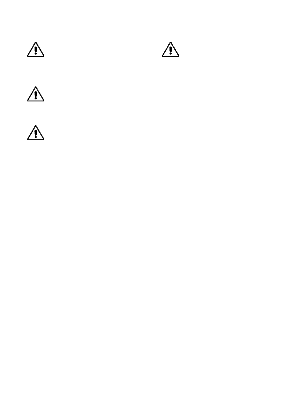
cause severe injuries.
This unit has many sharp edges that can
Installer Safety
In all areas of the world, equipment should
be installed in accordance with existing local codes.
Please contact your local authorities if you have any
questions.
Care should be taken to ensure that all basic safety
practices are followed during the installation and
servicing activities related to the installation and
service of Taylor equipment.
S Only Taylor authorized service personnel
should perform installation and repairs on
the equipment.
S Authorized service personnel should consult
OSHA Standard 29CFRI910.147 or the
applicable code of the local area for the
industry standards on lockout/tagout
procedures before beginning any installation
or repairs.
S Authorized service personnel must ensure
that the proper PPE is available and worn
when required during installation and
service.
S Authorized service personnel must remove
all metal jewelry, rings, and watches before
working on electrical equipment.
The main power supply(s) to the equipment
must be disconnected prior to performing any
repairs. Failure to follow this instruction may result in
personal injury or death from electrical shock or
hazardous moving parts as well as poor
performance or damage to the equipment.
Site Preparation
Review the area where the unit will be installed
before uncrating the unit. Make sure all possible
hazards to the user or equipment have been
addressed.
Electrical Connections
The grill is supplied with one power cord. Check the
data plate on the grill for voltage, cycle, phase and
electrical specifications.
For proper power connections, refer to the wiring
diagram provided inside the left side panel, attached
to the gas manifold assembly. The power connection
is located behind the access line cover on the front
of the grill.
In the United States, this equipment is intended to
be installed in accordance with the National
Electrical Code (NEC), ANSI/NFPA 70-1987. The
purpose of the NEC code is the practical
safeguarding of persons and property from hazards
arising from the use of electricity. This code contains
provisions considered necessary for safety.
Compliance therewith and proper maintenance will
result in an installation essentially free from hazard!
In all other areas of the world, equipment should be
installed in accordance with the existing local codes.
Please contact your local authorities.
The Proper Wire Size and Branch Circuit
Overcurrent Device shall be selected according to
the data label information and in accordance with
CEC Part I 2006, Section 14-100(e)(i).
Note:Allrepairsmustbeperformedbyan
authorized Taylor Service Technician.
Model 811, 813, 819, 821 Series To the Installer
1
FOLLOW YOUR LOCAL ELECTRICAL CODES!
131205
Page 6
CAUTION: THIS EQUIPMENT MUST BE
PROPERLY GROUNDED! FAILURE TO DO SO
CAN RESULT IN SEVERE PERSONAL INJURY
FROM ELECTRICAL SHOCK!
This unit is provided with an equipotential
grounding lug that is to be properly attached to the
rear of the frame by the authorized installer. The
installation location is marked by the equipotential
bonding symbol (5021 of IEC 60417-1) on both the
removable panel and the equipment's frame.
Installation
WARNING: Improper installation, adjustment,
alteration, service or maintenance can cause
property damage, injury or death. Read the
installation, operating and maintenance
instructions thoroughly before installing or
servicing this equipment.
This machine is designed for indoor use only.
DO NOT installthemachineinanarea
where a water jet could be used to clean or rinse the
machine. Failure to follow this instruction may result
in serious electrical shock.
S Stationary appliances which are not
equipped with a power cord and a plug or
another device to disconnect the appliance
from the power source must have an all-pole
disconnecting device with a contact gap of
at least 3 mm installed in the external
installation.
S Appliances that are permanently connected
to fixed wiring and for which leakage
currents may exceed 10 mA, particularly
when disconnected or not used for long
periods, or during initial installation, shall
have protective devices such as a GFI, to
protect against the leakage of current,
installed by the authorized personnel to the
local codes.
S Supply cords used with this unit shall be
oil-resistant, sheathed flexible cable not
lighter than ordinary polychloroprene or
other equivalent synthetic
elastomer-sheathed cord (Code designation
60245 IEC 57) installed with the proper cord
anchorage to relieve conductors from strain,
including twisting, at the terminals and
protect the insulation of the conductors from
abrasion.
If the supply cord is damaged, it must be
replaced by an authorized Taylor service
technician in order to avoid a hazard.
This grill must be installed on a level
surface. Failure to comply may result in personal
injury or equipment damage.
Installation of Cab le Kit
If the unit is permanently connected, the Cable Kit
must be installed. Flexible conduit must be used
when installing the appliance.
Ventilation and Clearance
To ensure proper operation of this appliance, it must
be installed so that the products of combustion are
efficiently removed.
After set up, do not store anything on top of
the grill. Failure to follow this instruction may result
in a fire hazard.
Grease Disposal Container
If the grill is not factory-equipped with grease
disposal containers, the store is required to provide
appropriate grease disposal containers in
accordance with NSF Standard 4 requirements.
2
Model 811, 813, 819, 821 SeriesTo the Installer
Page 7

Section 2 To the Operator
The Taylor grills included in this manual consist of
the base model numbers 811, 813, 819, and 821.
Prefix letters were added to the base model
numbers to denote minor design differences:
C = Standard Platen Length (17.5” / 445 mm)
L = Longer Platen Length (21” / 533 mm)
G = Grooved Option
The models 811 and 813 are 36” (914 mm) grills.
The 811 is equipped with three upper platens and
the 813 is equipped with two upper platens.
The models 819 and 821 are 24” (610 mm) grills.
The 819 is equipped with two upper platens and the
model 821 is equipped with one upper platen.
These grills are capable of cooking a variety of
products and feature two cooking options. They
provide all the features of a flat grill as well as the
advantages of two-sided cooking.
The grill you have purchased has been carefully
engineered and manufactured to provide
dependable operation. When properly operated and
maintained, it will produce a consistent quality
product. Like all mechanical products, it will require
cleaning and maintenance. A minimum amount of
care and attention is necessary if the operating
procedures in this manual are followed closely.
This Operator's Manual should be read before
operating or performing any maintenance on your
equipment.
It is strongly recommended that all personnel
responsible for the equipment's operation and
cleaning review these procedures for proper training
and assurance that no misunderstandings exist.
Note: Your Taylor warranty is valid only if the parts
are authorized Taylor parts, purchased from the
local authorized Taylor Distributor, and only if all
required service work is provided by an authorized
Taylor service technician. Taylor reserves the right
to deny warranty claims on units or parts if
non-Taylor approved parts or incorrect refrigerant
were installed in the unit, system modifications were
performed beyond factory recommendations, or it is
determined that the failure was caused by abuse,
misuse, neglect, or failure to follow all operating
instructions. For full details of your Taylor Warranty,
please see the Limited Warranty section in this
manual.
Note: Constant research results in steady
improvements; therefore, information in this
manual is subject to change without notice.
If the crossed out wheeled bin symbol is
affixed to this product, it signifies that this product is
compliant with the EU Directive as well as other
similar legislation in effect after August 13, 2005.
Therefore, it must be collected separately after its
use is completed, and cannot be disposed as
unsorted municipal waste.
The user is responsible for returning the product to
the appropriate collection facility, as specified by
your local code.
In the event you should require technical assistance,
please contact your local authorized Taylor
Distributor.
Model 811, 813, 819, 821 Series To the Operator
For additional information regarding applicable local
laws, please contact the municipal facility and/or
local distributor.
131205
3
Page 8
Section 3 Safety
We, at Taylor Company, are concerned about the
safety of the operator when he or she comes in
contact with the grill and its parts. Taylor has gone
to extreme efforts to design and manufacture built-in
safety features to protect both you and the service
technician. As an example, warning labels have
been attached to the grill to further point out safety
precautions to the operator.
IMPORTANT - Failure to adhere to the
following safety precautions may result in
severe personal injury or death. Failure to
comply with these warnings may damage the
machine and its components. Component
damage will result in part replacement expense
and service repair expense.
To Op erate Safely:
DO NOT operate the grill without reading
this operator's manual. This manual should be kept
in a safe place for future reference.
This appliance is to be used only by trained
personnel. It is not intended for use by children or
people with reduced physical, sensory, or mental
capabilities, or lack of experience and knowledge,
unless given supervision or instruction concerning
the use of the appliance by a person responsible for
their safety. Children should be supervised to ensure
that they do not play with the appliance.
Failure to follow the instructions below may
result in severe injury or death from electrocution:
S DO NOT operate the grill unless it is
properly grounded.
S DO NOT operate the grill with larger fuses
than specified on data label.
S DO NOT operate the grill unless all service
panels and access doors are attached with
screws.
S All repairs must be performed by an
authorized Taylor service technician.
S The main power supplies to the grill must be
disconnected prior to performing any
repairs.
S For Cord Connected Units: Only Taylor
authorized service technicians or licensed
electricians may install a plug or
replacement cord on these units.
S Stationary appliances which are not
equipped with a power cord and a plug or
other device to disconnect the appliance
from the power source must have an all-pole
disconnecting device with a contact gap of
at least 3 mm installed in the external
installation.
S Appliances that are permanently connected
to fixed wiring and for which leakage
currents may exceed 10 mA, particularly
when disconnected or not used for long
periods, or during initial installation, shall
have protective devices such as a GFI, to
protect against the leakage of current,
installed by the authorized personnel to the
local codes.
S Supply cords used with this unit shall be
oil-resistant, sheathed flexible cable not
lighter than ordinary polychloroprene or
other equivalent synthetic elastomersheathed cord, (Code designation 60245
IEC 57), installed with the proper cord
anchorage to relieve conductors from strain,
including twisting, at the terminals and
protect the insulation of the conductors from
abrasion.
If the supply cord is damaged, it must be
replaced by the manufacturer, its service
agent, or similarly qualified person, in order
to avoid a hazard.
130415
4
Model 811, 813, 819, 821 SeriesSafety
Page 9
IMPORTANT: DO NOT use a water jet or
spray excessive water on or anywhere near the
grill. Failure to follow this instruction may result in
serious electrical shock and cause permanent
electrical and mechanical damage to internal parts.
Failure to follow this instruction may result in:
DO NOT use cold water or ice to cool the
upper platen or the lower cook surface. Failure to
follow this instruction may result in:
S serious electrical shock
S serious electrical shock
S burns from hot steam
S liquid collecting inside the grill and
destroying electrical components
This appliance must be isolated from all
combustible construction and materials including,
but not limited to; walls, partitions, furniture, floors,
curtains, paper, boxes, and decorations. Failure to
comply may result in fire and cause destruction and
severe injury.
FORYOURSAFETY
Do not store or use gasoline or other
flammable vapors or liquids in the vicinity of
this or any other appliance.
S burns from hot steam
S liquid collecting inside the grill and
destroying electrical components
Take caution to protect eyes, lungs, and all
parts of the body from potential harm when using
any chemical cleaner. Failure to follow this
instruction may result in a chemical burn.
DO NOT use any abrasives or cleaners
other than approved food service cleaners and
degreasers. Failure to comply may cause illness to
the consumer and may also damage grill surfaces.
This grill must be installed on a level
surface. Failure to comply may result in personal
injury or equipment damage.
For thorough cleaning, the grill must be
pulled away from the wall. Before moving the grill,
USE EXTREME CAUTION while setting up,
operating, and cleaning the grill.
S Avoid coming in contact with hot grill
surfaces or with hot grease.
S DO NOT prepare or remove product without
proper equipment.
S DO NOT allow untrained personnel to
operate this grill.
Failure to follow these instructions can result in burn
injuries.
Model 811, 813, 819, 821 Series Safety
remove the grease cans. Turn off the gas at the
quick connect shut-off valve on the flexible hose.
Disconnect the gas quick connector. Disconnect the
tether to the grill, located on the back panel of the
unit.
To return the grill to its original position, reverse the
steps. Use extreme caution to smoothly and slowly
roll the grill backward into place.
Failure to do so may cause the grill to tip and can
result in severe equipment damage or personal
injury.
5
Page 10
Cleaning and sanitizing schedules are
governed by your state or local regulatory agencies
and must be followed accordingly. Please refer to
the cleaning section of this manual for the proper
procedure to clean this unit.
Access to the service area of the unit is
restricted to persons having knowledge and practical
experience with the appliance, in particular as far as
safety and hygiene are concerned.
S DO NOT obstruct the ventilation openings at
the rear of this appliance.
S DO NOT obstruct the flow of air in and
around the grill.
NOTICE all warning labels that have been
attached to the grill to further point out safety
precautions to the operator.
This piece of equipment is made in America and has
American sizes on hardware. All metric conversions
are approximate and vary in size.
NOISE LEVEL: Airborne noise emission does not
exceed 70 dB(A) when measured at a distance of
1.0 meter from the surface of the machine and at a
height of 1.6 meters from the floor.
These instructions are valid only if the country code
symbol appears on the appliance. If the symbol does
not appear on the appliance, refer to the technical
instructions which give the necessary instructions for
adapting the appliance to the utilization conditions of
that country.
130304
6
Model 811, 813, 819, 821 SeriesSafety
Page 11
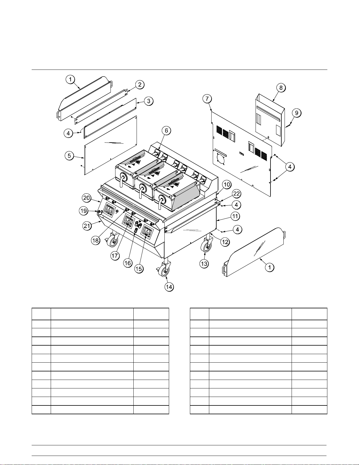
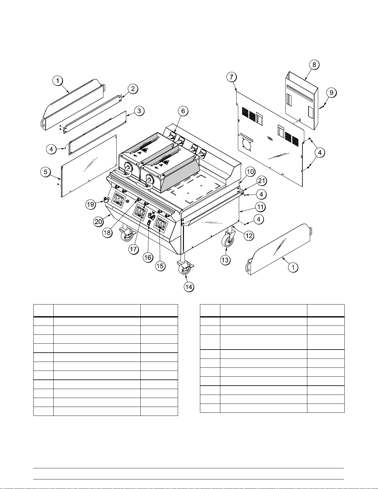
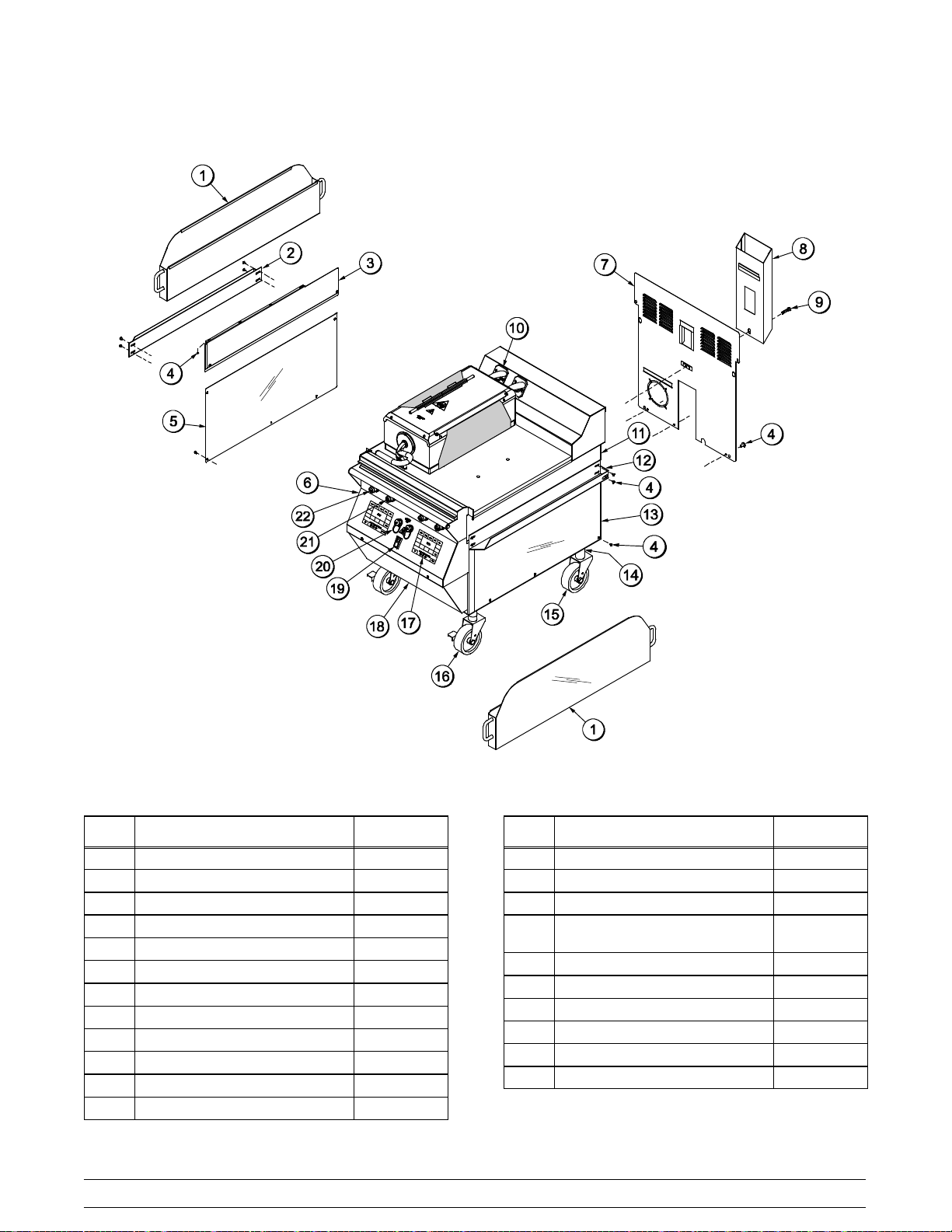
Section 4 Operator Parts Identification
C811 Exploded View
Figure 1
ITEM DESCRIPTION PART NO.
1 CAN A.-GREASE X80925
2 SLIDE-GREASE CAN LEFT 069936
3 PANEL-SIDE-UPPER *LEFT 073990
4 SCREW-10-32X3/8SLTD TRUS 024298
5 PANEL-SIDE-LOWER*LEFT 073992
*6 KIT A.-GREASE SHIELD X78330-SER
7 PANEL A.-BACK SERVICE X73993
8 DEFLECTOR A.-FLUE X69555
9 SCREW-3/8-16X34SERR HWH 017328
10 PANEL-SIDE-UPPER*RIGHT 073989
11 PANEL-SIDE-LOWER*RIGHT 073991
Model 811, 813, 819, 821 Series Operator Parts Identification
ITEM DESCRIPTION PART NO.
12 NUT-JAM 1-1/2-12 (2 PCS) 073594
13 CASTER-5" 7-5/8 STEM 078377
14 CASTER-GRILL 5” SWIVEL LOC 073240
15 KIT A.-GRILL CONTROL GEN X73474-SER
16 SWITCH-ROCKER-DPST-10A 076989-WP
17 BUTTON-OPERATOR-BLACK 076012
18 BUTTON-OPERATOR-RED 076011
19 COVER A.-USB WATERPROOF 068583
20 PANEL A.-FRONT UPPER X69550
21 PANEL A.-FRONT-LOWER X73979
22 SLIDE-GREASE CAN RIGHT 069935
*NOTE: 1 KIT PER PLATEN
121003
7
Page 12
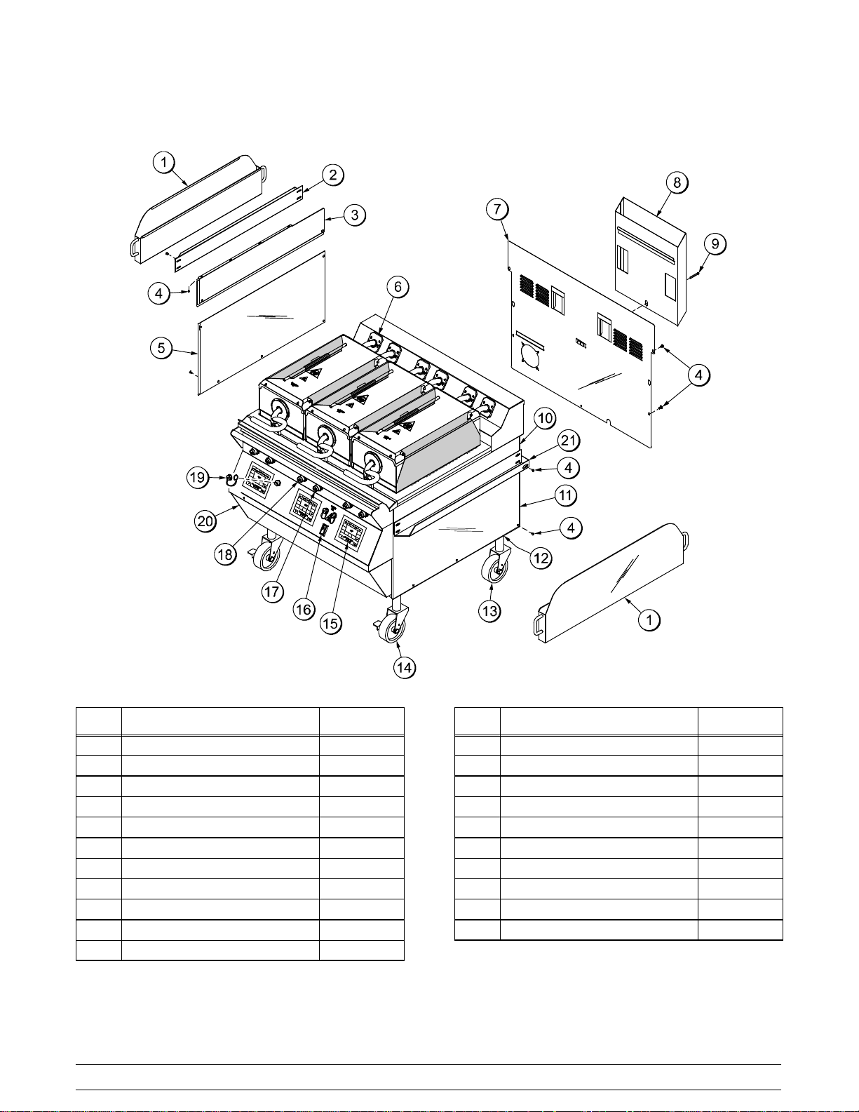
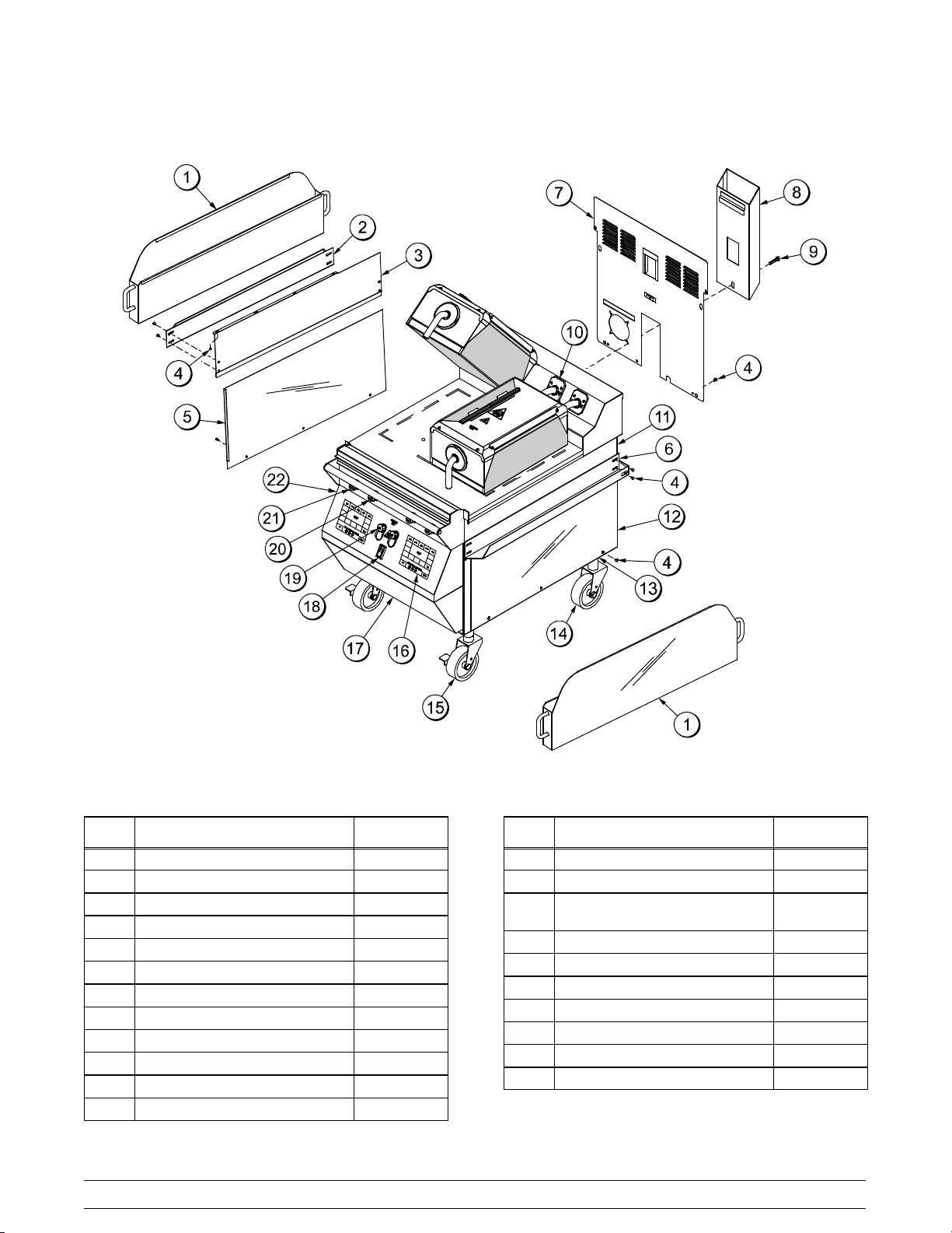
L811 Exploded View
ITEM DESCRIPTION PART NO.
1 CAN A.-GREASE X80925
2 SLIDE-GREASE CAN LEFT 069936
3 PANEL-SIDE-UPPER *LEFT 073990
4 SCREW-10-32X3/8SLTD TRUS 024298
5 PANEL-SIDE-LOWER*LEFT 073992
*6 KIT A.-GREASE SHIELD X78330-SER
7 PANEL A.-BACK SERVICE X73993
8 DEFLECTOR A.-FLUE X69555
9 SCREW-3/8-16X34SERR HWH 017328
10 PANEL-SIDE-UPPER*RIGHT 073989
11 PANEL-SIDE-LOWER*RIGHT 073991
120907
Figure 2
8
ITEM DESCRIPTION PART NO.
12 NUT-JAM 1-1/2-12 (2 PCS) 073594
13 CASTER-5" 7-5/8 STEM 078377
14 CASTER-GRILL 5” SWIVEL LOC 073240
15 KIT A.-GRILL CONTROL GEN X73474-SER
16 SWITCH-ROCKER-DPST-10A 076989-WP
17 BUTTON-OPERATOR-BLACK 076012
18 BUTTON-OPERATOR-RED 076011
19 COVER A.-USB WATERPROOF 068583
20 PANEL A.-FRONT-LOWER X73979
21 SLIDE-GREASE CAN RIGHT 069935
*NOTE: 1 KIT PER PLATEN
Model 811, 813, 819, 821 SeriesOperator Parts Identification
Page 13
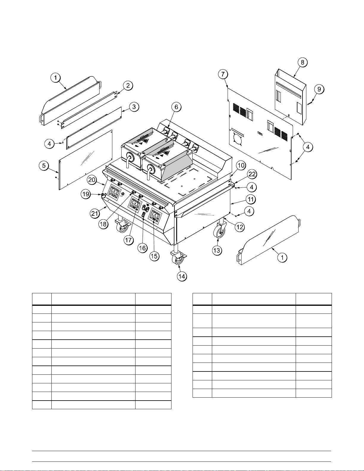
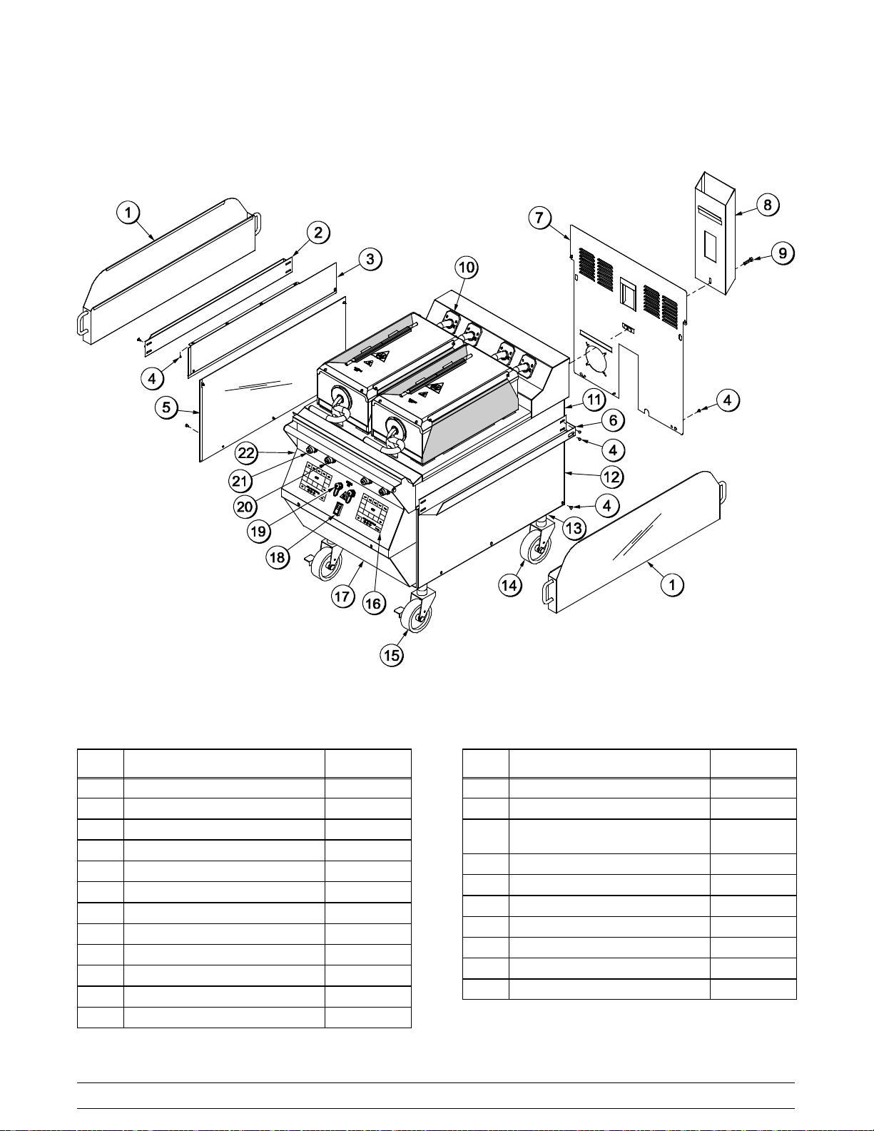
C813 Exploded View
Figure 3
ITEM DESCRIPTION PART NO.
1 CAN A.-GREASE X80925
2 SLIDE-GREASE CAN LEFT 069936
3 PANEL-SIDE-UPPER *LEFT 073990
4 SCREW-10-32X3/8SLTD TRUS 024298
5 PANEL-SIDE-LOWER-LEFT 073992
*6 KIT A.-GREASE SHIELD X78330-SER
7 PANEL A.-BACK SERVICE X73993
8 DEFLECTOR A.-FLUE X69555
9 SCREW-3/8-16X3/4 SERRATED 017328
10 PANEL-SIDE-UPPER*RIGHT 073989
11 PANEL-SIDE-LOWER-RIGHT 073991
12 NUT-JAM 1 1/2-12 STEEL 073594
Model 811, 813, 819, 821 Series Operator Parts Identification
ITEM DESCRIPTION PART NO.
13 CASTER-5" 7-5/8 STEM 078377
14 CASTER-GRILL 5" SWIVEL
W/LOCK
15 KIT A.-GRILL CONTROL GEN X73474-SER
16 SWITCH-ROCKER-DPST-10A 076989-WP
17 BUTTON-OPERATOR-BLACK 076012
18 BUTTON-OPERATOR-RED 076011
19 COVER A.-USB WATERPROOF 068583
20 PANEL A.-FRONT UPPER X69550
21 PANEL A.-FRONT-LOWER X73979
22 SLIDE-GREASE CAN RIGHT 069935
*NOTE: 1 KIT PER PLATEN
9
073240
121003
Page 14
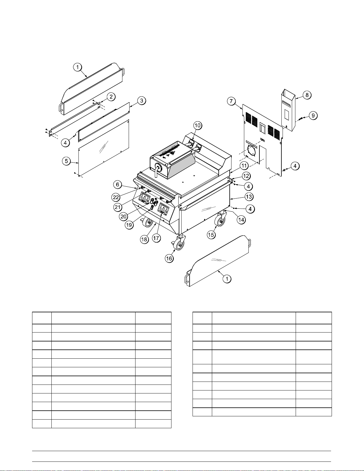
L813 Exploded View
ITEM DESCRIPTION PART NO.
1 CAN A.-GREASE X80925
2 SLIDE-GREASE CAN LEFT 069936
3 PANEL-SIDE-UPPER *LEFT 073990
4 SCREW-10-32X3/8SLTD TRUS 024298
5 PANEL-SIDE-LOWER-LEFT 073992
*6 KIT A.-GREASE SHIELD X78330-SER
7 PANEL A.-BACK SERVICE X73993
8 DEFLECTOR A.-FLUE X69555
9 SCREW-3/8-16X3/4 SERRATED 017328
10 PANEL-SIDE-UPPER*RIGHT 073989
11 PANEL-SIDE-LOWER-RIGHT 073991
120907
Figure 4
10
ITEM DESCRIPTION PART NO.
12 NUT-JAM 1 1/2-12 STEEL 073594
13 CASTER-5" 7-5/8 STEM 078377
14 CASTER-GRILL 5" SWIVEL
W/LOCK
15 KIT A.-GRILL CONTROL GEN X73474-SER
16 SWITCH-ROCKER-DPST-10A 076989-WP
17 BUTTON-OPERATOR-BLACK 076012
18 BUTTON-OPERATOR-RED 076011
19 COVER A.-USB WATERPROOF 068583
20 PANEL A.-FRONT-LOWER X73979
21 SLIDE-GREASE CAN RIGHT 069935
*NOTE: 1 KIT PER PLATEN
073240
Model 811, 813, 819, 821 SeriesOperator Parts Identification
Page 15
C819 Exploded View
Figure 5
ITEM DESCRIPTION PART NO.
1 CAN A.-GREASE X80925
2 SLIDE-GREASE CAN LEFT 069936
3 PANEL-SIDE UPPER-LEFT 073990
4 SCREW-10-32X3/8SLTD TRUS 024298
5 PANEL-SIDE-LOWER-LEFT 073992
6 SLIDE-GREASE CAN RIGHT 069935
7 PANEL A.-BACK SERVICE X69664
8 DEFLECTOR A.-FLUE X69657
9 SCREW-3/8-16X1-1/2 SERR 020129
*10 KIT A.-GREASE SHIELD X78330-SER
11 PANEL-SIDE UPPER-RIGHT 073989
12 PANEL-SIDE-LOWER-RIGHT 073991
Model 811, 813, 819, 821 Series Operator Parts Identification
ITEM DESCRIPTION PART NO.
13 NUT-JAM 1 1/2-12 STEEL 073594
14 CASTER-5" 7-5/8 STEM 078377
15 CASTER-GRILL 5" SWIVEL
W/LOCK
16 KIT A.-GRILL CONTROL X73474-SER
17 PANEL A.-FRONT-LOWER X69660
18 SWITCH-ROCKER-DPST-10A 076989-WP
19 COVER A.-USB WATERPROOF 068583
20 BUTTON-OPERATOR-BLACK 076012
21 BUTTON-OPERATOR-RED 076011
22 PANEL A.-LIGHT X80626
*NOTE: 1 KIT PER PLATEN
11
073240
121106
Page 16
L819 Exploded View
ITEM DESCRIPTION PART NO.
1 CAN A.-GREASE X80925
2 SLIDE-GREASE CAN LEFT 069936
3 PANEL-SIDE UPPER-LEFT 073990
4 SCREW-10-32X3/8SLTD TRUS 024298
5 PANEL-SIDE-LOWER-LEFT 073992
6 SLIDE-GREASE CAN RIGHT 069935
7 PANEL A.-BACK SERVICE X69664
8 DEFLECTOR A.-FLUE X69657
9 SCREW-3/8-16X1-1/2 SERR 020129
*10 KIT A.-GREASE SHIELD X78330-SER
11 PANEL-SIDE UPPER-RIGHT 073989
12 PANEL-SIDE-LOWER-RIGHT 073991
130316
Figure 6
12
ITEM DESCRIPTION PART NO.
13 NUT-JAM 1 1/2-12 STEEL 073594
14 CASTER-5" 7-5/8 STEM 078377
15 CASTER-GRILL 5" SWIVEL
W/LOCK
16 KIT A.-GRILL CONTROL X73474-SER
17 PANEL A.-FRONT-LOWER X69660
18 SWITCH-ROCKER-DPST-10A 076989-WP
19 COVER A.-USB WATERPROOF 068583
20 BUTTON-OPERATOR-BLACK 076012
21 BUTTON-OPERATOR-RED 076011
22 PANEL A.-LIGHT X80626
*NOTE: 1 KIT PER PLATEN
073240
Model 811, 813, 819, 821 SeriesOperator Parts Identification
Page 17
C821 Exploded View
Figure 7
ITEM DESCRIPTION PART NO.
1 CAN A.-GREASE X80925
2 SLIDE-GREASE CAN LEFT 069936
3 PANEL-SIDE UPPER-LEFT 073990
4 SCREW-10-32X3/8SLTD TRUS 024298
5 PANEL-SIDE-LOWER-LEFT 073992
6 PANEL A.-LIGHT X80626
7 PANEL A.-BACK SERVICE X69664
8 DEFLECTOR A.-FLUE X69657
9 SCREW-3/8-16X1-1/2 SERR 020129
*10 KIT A.-GREASE SHIELD X78330-SER
11 PANEL-SIDE UPPER-RIGHT 073989
12 SLIDE-GREASE CAN RIGHT 069935
Model 811, 813, 819, 821 Series Operator Parts Identification
ITEM DESCRIPTION PART NO.
13 PANEL-SIDE-LOWER-RIGHT 073991
14 NUT-JAM 1 1/2-12 STEEL 073594
15 CASTER-5" 7-5/8 STEM 078377
16 CASTER-GRILL 5" SWIVEL
W/LOCK
17 KIT A.-GRILL CONTROL X73474-SER
18 PANEL A.-FRONT-LOWER X69660
19 SWITCH-ROCKER-DPST-10A 076989-WP
20 COVER A.-USB WATERPROOF 068583
21 BUTTON-OPERATOR-BLACK 076012
22 BUTTON-OPERATOR-RED 076011
*NOTE: 1 KIT PER PLATEN
13
073240
121106
Page 18
L821 Exploded View
ITEM DESCRIPTION PART NO.
1 CAN A.-GREASE X80925
2 SLIDE-GREASE CAN LEFT 069936
3 PANEL-SIDE UPPER-LEFT 073990
4 SCREW-10-32X3/8SLTD TRUS 024298
5 PANEL-SIDE-LOWER-LEFT 073992
6 PANEL A.-LIGHT X80626
7 PANEL A.-BACK SERVICE X69664
8 DEFLECTOR A.-FLUE X69657
9 SCREW-3/8-16X1-1/2 SERR 020129
*10 KIT A.-GREASE SHIELD X78330-SER
11 PANEL-SIDE UPPER-RIGHT 073989
12 SLIDE-GREASE CAN RIGHT 069935
130318
Figure 8
14
ITEM DESCRIPTION PART NO.
13 PANEL-SIDE-LOWER-RIGHT 073991
14 NUT-JAM 1 1/2-12 STEEL 073594
15 CASTER-5" 7-5/8 STEM 078377
16 CASTER-GRILL 5" SWIVEL
W/LOCK
17 KIT A.-GRILL CONTROL X73474-SER
18 PANEL A.-FRONT-LOWER X69660
19 SWITCH-ROCKER-DPST-10A 076989-WP
20 COVER A.-USB WATERPROOF 068583
21 BUTTON-OPERATOR-BLACK 076012
22 BUTTON-OPERATOR-RED 076011
*NOTE: 1 KIT PER PLATEN
073240
Model 811, 813, 819, 821 SeriesOperator Parts Identification
Page 19
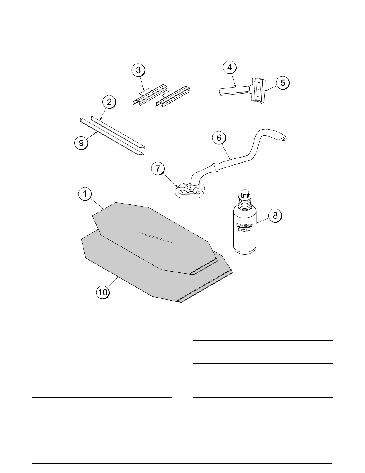
Accessories
Figure 9
ITEM DESCRIPTION PART NO.
1 SHEET-RELEASE - BOX OF 9
(C811, C813, C819, C821)
*2 RETAINER-SHEET RELEASE
(RETENTION BAR) (C811,
C813, C819, C821)
**3 CLIP-RELEASE MATERIAL
W/TAB
4 SCRAPER-TEFLON WIPER 075887
5 STRIP-REPLACEMENT 075888
073442
072845
072673
Model 811, 813, 819, 821 Series Operator Parts Identification
ITEM DESCRIPTION PART NO.
***6 HOLDER-CLEANING 073736
***7 PAD-CLEANING 073737
8 CLEANER-STERA SHEEN
(CASE OF 6, 1 QT. BOTTLES)
*9 RETAINER-SHEET RELEASE
(RETENTION BAR) (L811, L813,
L819, L821)
10 SHEET-RELEASE -BOX OF 9
(L811, L813, L819, L821)
* SHOWN PER PLATEN
** SHOWN PER PLATEN
(NOTE: EXTRA CLIPS ARE SENT WITH GRILL)
*** SOLD SEPARATELY THROUGH YOUR LOCAL
DISTRIBUTOR
15
073160
080594
080595
120720
Page 20

Section 5 Important: To the Operator
Note: The Model 811 three platen grill has been selected for illustration purposes.
Figure 10
ITEM DESCRIPTION
1 RAISE BUTTON
2 STANDBY/COOK MODE BUTTON
3 USB COVER/CONNECTION
4 POWER SWITCH
5 CLEAN MODE KEY
120604
ITEM DESCRIPTION
6 PROGRAM KEY
7 TEMPERATURE INDICATOR LIGHTS
8 POWER KEY
9 FUNCTION DISPLAY
10 MENU SELECT KEYS
16
Model 811, 813, 819, 821 SeriesImportant: To the Operator
Page 21

Section 6 Operating Procedures
The three platen Model L811 has been selected to
illustrate the step-by-step procedures. For grills
equipped with less than three platens, perform the
following steps as appropriate for your grill platen
configuration.
Daily Opening Procedures
Before operating the grill, the release sheets must
be installed on the upper platens. The release
sheets are reversed and rotated on a daily basis
(black side vs. gray side.)
Perform the following steps for installing release
sheets:
CAUTION: Make sure the grill is COOL
before attempting to install or remove release
sheets.
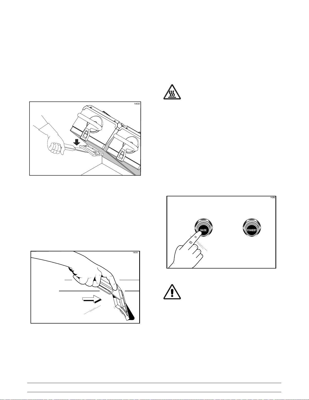
Step 1
Slide the release sheet retainer through the hemmed
end of the release sheet.
Step 2
Hook the release sheet retainer on the release sheet
shoulder screws at the top of the upper platen.
Figure 12
Step 3
Hold the non-hemmed end of the release sheet.
Gently pull the sheet tight, wrapping it around the
platen in a side-to-side manner.
Figure 13
Note: Check the alignment of the release sheet and
Figure 11
Model 811, 813, 819, 821 Series Operating Procedures
make sure it fits smoothly over the upper platen.
130206
17
Page 22

Step 4
Place the release sheet clips over the release sheet.
Press them into place over the release sheet bar at
the top of the platen.
Figure 14
Step 5
Check the tightness of the release sheet against the
upper platen.
Step 6
Repeat steps 1 through 5 for the remaining upper
platen(s).
Note: Temperature checks should only be
conducted with the release sheets removed.
Replace the release sheet when:
S Cleaning procedures fail to remove all
buildup and product sticks to the release
sheet.
S A tear appears in the cooking area of the
release sheet, causing product to stick to the
release sheet.
Figure 15
Note: Installing the release sheets too tightly may
cause p remature failure of the sheet.
Figure 16
CAUTION: The upper platen surface and
release sheet are very hot. To prevent burn
injuries, wear heat-resistant gloves when
replacing the release sheets.
Note: It is not necessary to change the release
sheet if small pin holes develop on the sheet.
130205
18
Model 811, 813, 819, 821 SeriesOperating Procedures
Page 23
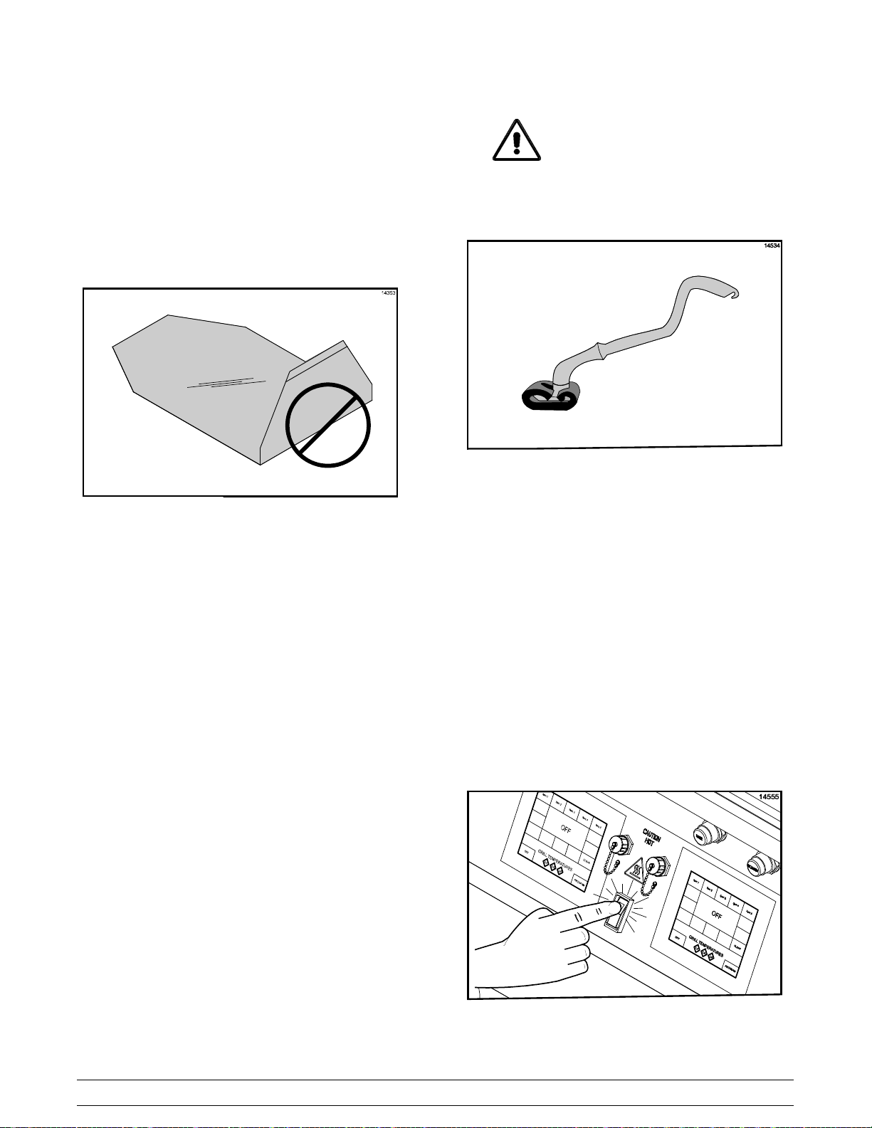
Care of Release Sheets
DO NOT:
S DO NOT fold or crease.
Figure 17
S DO NOT touch with sharp objects, grill
scrapers, or abrasive pads.
S DO NOT place under other equipment or
objects.
IMPORTANT! Clean the release
sheets using the grill cleaning pad and
holder identified on page 15 ONLY. Using
any other pad and holder will damage the
release sheets.
Figure 18
Note: Contact your local Taylor Distributor to
purchase the correct grill cleaning pad and holder.
(See page 15.)
S DO rinsetoremovecleanerandallowtodry
onaflatsurface.
S DO rotate the release sheet daily and
re-install on opposite side than previously
used (black side vs. brown side).
StartUpoftheGrill
S DO NOT hot-hose or soak in water.
DO:
IMPORTANT! The lower grill surface and the
upper platen MUST BE CLEAN before starting
these procedures.
Step 1
Place the power switch in the ON position.
S DO clean with a squeegee after each run of
product.
S DO wipe with a clean, sanitizer-soaked grill
cloth a minimum of 4 times per hour and
more often during peak periods.
S DO clean daily on both sides, using an
approved high temperature grill cleaner and
the grill cleaning pad and holder identified
on page 15.
Model 811, 813, 819, 821 Series Operating Procedures
19
Figure 19
110602
Page 24

The control will display the word “INITIALIZATION”
for five seconds and then will enter the OFF mode,
displaying the message “OFF”. The temperature
indicators will not be illuminated. A tone will sound
for 2 0 seconds unless the operator touches the
display screen, raise button or the standby button.
Figure 20
Note: If an ignition failure fault occurs upon start up,
press the center of the control. The control will
display “OFF”. Refer to problem #2, items a, b, and c
of the Gas Grill Troubleshooting Guide on page 42.
After five minutes has elapsed, press the menu key
again. If the ignition failure fault was not resolved,
please call your authorized service technician.
Step 2
Touch a menu key on the control to start the grill.
The grill will start heating up to the proper
temperature. The control will display the selected
menu item and indicate “BOTTOM TOO COOL” and
“TOP TOO COOL”. The grill temperature indicators
will be illuminated in amber.
Figure 21
Figure 22
When the grill is at the proper temperature, the
temperature statements will no longer display and
the temperature indicators will be illuminated in
green.
Figure 23
20
Model 811, 813, 819, 821 SeriesOperating Procedures
Page 25
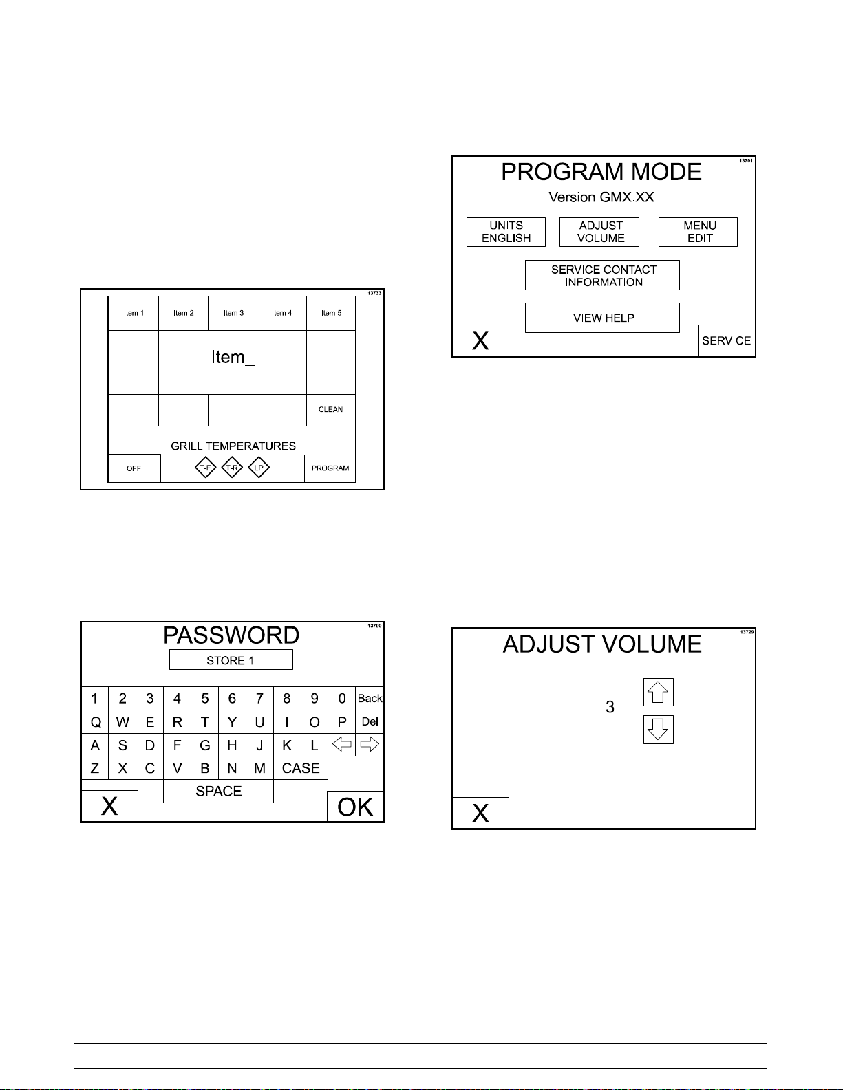
Programming Menu Items
To enter the Program Mode, the grill control must be
in the OFF or IDLE mode.
Step 1
Press and hold the PROGRAM key for
approximately five seconds to enter the Program
Mode.
Figure 24
Step 3
The PROGRAM MODE screen will appear.
Figure 26
UNITS Key
TheUNITSkeyisusedtoselecteitherEnglishor
metric units of measure. The UNITS key toggles
between F and C with each key press.
Step 2
The PASSWORD screen will appear. Enter the
Operator Password “STORE1” and press the OK
key.
Figure 25
ADJUST VOLUME Key
The ADJUST VOLUME key displays the current
volume. To increase or decrease the volume, use
the UP and DOWN arrow keys.
Figure 27
Model 811, 813, 819, 821 Series Operating Procedures
21
Page 26

MENU EDIT Key
The MENU EDIT key is used to program a menu
item. When the MENU EDIT key is pressed, the
following screen will display.
Figure 28
If there is more than one screen of menu items,
press the Previous or Next arrow keys to access the
other menu items.
Press the menu item key to be programmed. The
following screen will display.
To edit a menu item, press the menu item key to
bring up a virtual keyboard. Type in the desired
name (up to 8 characters per line) and then press
the “X” key to return to the previous screen.
Figure 30
ACTIVE: YES or NO. This key displays the current
selection. Pressing the key toggles to the opposite
selection. Selecting YES will display the menu item
on the main display screen.
TOP TEMP: This key displays the current set point
temperature for the platen. To increase or decrease
the temperature, use the UP and DOWN arrow keys.
BOTTOM TEMP: This key displays the current set
point temperature for the lower grill surface. To
increase or decrease the temperature, use t he UP
andDOWNarrowkeys.
Figure 29
Note: When setting the temperatures for a given
item, the limits are 150°F to 450°F (66°C to 232°C)
for the upper platen and 150°F to 400°F (66°C to
204°C) for the lower grill surface. If the temperatures
are set lower or higher than the temperature limits,
the set point at the control will default to 150°F and
450°F (66°C and 232°C) respectively.
CLAM/FLAT: This key displays the current setting
(CLAM or FLAT) associated with that function.
Pressing the key toggles the mode to the opposite
selection.
GAP: This key is only active if CLAM has been
selected. The key displays the platen gap (in inches
or mm) associated with the FUNCTION. To increase
or decrease the gap setting, use the UP and DOWN
arrow keys.
22
Model 811, 813, 819, 821 SeriesOperating Procedures
Page 27

MULTIPLE TIMING FUNCTIONS: There are four
timing functions for clam and flat menu items. Each
function has a set of parameters associated with it.
The functions currently associated with the menu
item are displayed. Pressing function 1, function 2,
or function 3 will bring up the next function in the list.
The functions provided are:
S REMOVE IN
S SEAR IN
S TURN IN
S SEAR/TURN IN
ALARM AUTO/MANUAL: Thiskeydisplaysthe
current status of the alarm mode. Pressing the key
toggles the mode to the opposite selection.
If ALARM AUTO is selected, the alarm will
automatically stop after five seconds has elapsed.
Selecting ALARM MANUAL requires the operator
touchanywhereonthedisplayscreenortheraiseor
standby buttons to stop the alarm.
XXX SECONDS: This key displays the time
associated with that menu item in seconds. To
increase or decrease the seconds setting, use the
UP and DOWN arrow keys.
Figure 31
VIEW HELP Key
The View Help key is not functional at this time
(future development).
LoadingStoreMenuItemsToUSB
ThesameUSBflashdrivethatwasusedtoload
softwareintothegrillcanbeusedtoperformthis
procedure.
Step 1
Remove the USB cable cap from the USB connector
to access the USB port.
GAP: Each timing function has an associated gap
setting. This setting can be changed selecting the
gap value. Then use the UP and DOWN arrow keys
to increase and decrease the gap value.
Upon completion of all programming selections,
save the selections by pressing the OK key. To
return to the main display screen without saving the
programming selections, press the X key.
SERVICE CONTACT INFORMATION Key
Press the SERVICE CONTACT INFORMATION key
to view the programmed service contact information.
Note: Grills built prior to serial number M1035495
will require the front control panel be lowered to
access the control display boards.
Step 2
Insert the USB flash drive into the USB port.
Step 3
Press and hold the PROGRAM key for 5 seconds to
enter the Program Mode.
Figure 32
140421
Model 811, 813, 819, 821 Series Operating Procedures
23
Page 28

Step 4
Enter the Operator Password “STORE1” and press
the OK key.
Step 7
Enter a file name (up to 8 characters) to save the
menu items, using the keyboard displayed on the
control. Press the OK key. The menu items are
saved to the USB flash drive.
Step 8
Remove the USB flash drive from the USB port and
reinstall the USB cable cap on the USB connector.
Note: Grills built prior to serial number M1035495
will require the front control panel be reinstalled.
Figure 33
Step 5
Press the MENU EDIT key.
Figure 34
Step 6
Press the STORE MENU TO USB key.
LoadingMenuItemsFromUSB
OncethepropersoftwareisloadedontheUSBflash
drive, the next control board can be programmed
from the USB flash drive.
Step 1
Repeat Steps 1 through 5 from “Loading Store Menu
Items to USB.”
Step 2
Press the LOAD MENU FROM USB key.
Step 3
The control can display up to 5 different menu
options loaded on the USB flash drive. Select the
key for the correct menu to load. The control will
display “DONE” at the bottom of the screen when
the menu is loaded.
Step 4
Remove the USB flash drive from the USB port and
reinstall the USB cable cap on the USB connector.
110603
Figure 35
Step 5
To load menu items from the USB flash drive to
another control board, repeat these software loading
procedures.
Note: Grills built prior to serial number M1035495
will require the front control panel be reinstalled.
24
Model 811, 813, 819, 821 SeriesOperating Procedures
Page 29

Patty Placement & Removal
Placement procedures of meat products must be
followed on the grill. The meat must be placed on
the lower grill surface from front to back. When the
cook cycle is complete, the upper platen will raise.
Note: It is very important that all patties be
removed from the lower grill surface in the same
sequence that they were placed before cooking.
L Series Grills (Longer PlatenVersion)
Patties must be removed immediately after the
upper platen has been raised to the OPEN position
and after the meat has been seasoned.
Patties are generally placed two at a time from front
to back of grill and right to left. The removal order of
the patties is shown in the diagrams by the number
shown in the center of each patty.
130312
Model 811, 813, 819, 821 Series Operating Procedures
25
Page 30

Patty Placement & Removal (continued)
C Series Grills (Shorter Platen Version)
130312
26
Model 811, 813, 819, 821 SeriesOperating Procedures
Page 31

Operating Procedures
Cooking Product
Step 1
Selectthemenuitemtobecooked.Thegrillisatthe
correct temperature if the control does not display
any temperature statements and the grill
temperature indicators are green.
Step 2
Quickly place the product on the lower grill surface,
from front to back.
During the cooking cycle, the display will show the
name of the current menu item, “REMOVE IN”, and
the time remaining until the product should be
removed.
Figure 37
Step 3
Press the STANDBY button once.
Figure 36
The d isplay reads “MOVING DOWN” as the platen
lowers to the cook surface.
At the end of the cook cycle, the control will display
“DONE”, a tone will sound, and the platen will
automatically raise.
Figure 38
Note: To cancel a cook cycle at any time, press the
RAISE button. A tone will sound and the display will
read “CANCEL” for five seconds and then enter an
IDLE mode.
Model 811, 813, 819, 821 Series Operating Procedures
27
Page 32

Standby Procedures
Menu Parameters
Whenever the grill is idle and product is not being
cooked,theupperplatenmustbeplacedinthe
STANDBY position.
Step 1
To place the upper platen in the STANDBY position,
press the STANDBY button twice from the open
position.
Figure 39
The control will display “GOING TO STANDBY” and
then change to display “STANDBY”.
To view the settings and actual temperatures for the
current item, press and hold the menu item key a
minimum of 5 seconds. The screen will display the
cook time, gap setting, temperature set points and
actual temperature readings for each zone for that
menu item.
Figure 41
If a key is not pressed for 20 seconds, the grill
control will return to the normal display. Pushing the
“X” key will bring the display back to the main display
page.
Step 2
To raise the upper platen to the OPEN position to
resume cooking, press the RAISE button.
Figure 40
CAUTION: Never use force to raise the
upper platen. Damage to components may
result. Only use the RAISE button to open the
upper platen!
Cleaning After Each Run of Product
Step 1
Using the grill scraper, scrape the grease on the
lower g rill surface from front to back. Do not scrape
across the rear of the lower grill surface with the grill
scraper.
Figure 42
28
Model 811, 813, 819, 821 SeriesOperating Procedures
Page 33
Step 2
Use the wiper squeegee to clean the r elease sheet
on the upper platen. Hold the handle at a slight
upward angle. Use a downward motion to clean the
sheet. (Note: Do not use excessive pressure when
wiping the release sheet with the squeegee, as this
can scratch or tear the release sheet.)
Figure 43
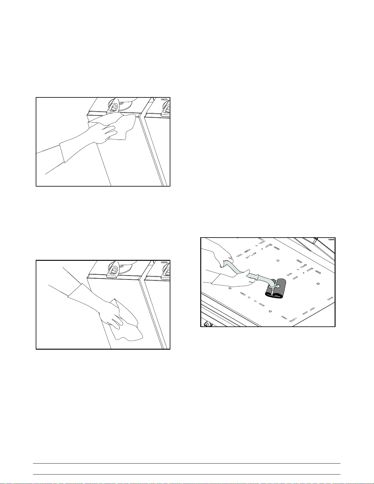
Step 4
Usethegrillclothtocleanthebacksplashplateand
the bullnose areas as needed during operation.
Note: To increase the life of the release sheet, wipe
it with a clean, sanitizer-soaked, folded grill cloth a
minimum of four times every hour.
CAUTION: The upper platen surface is
very HOT! To prevent burn injuries, use extreme
caution when wiping the release sheet.
Daily Cleaning Procedures
Note: The three platen Model L811 has been
selected to illustrate the step-by-step procedures.
For grills equipped with less than three platens,
perform the following steps as appropriate for your
grill platen configuration.
Step 1
Raise the upper platen to the OPEN position by
pressing the red RAISE button.
Step 3
Using the wiper squeegee, push the grease at the
rear of the lower grill surface into the grease can. Do
not use the grill scraper for this step.
Figure 44
CAUTION: Never use force to raise the
upper platen. Damage to components may
result. O nly use the RAISE button to open the
upper platen!
Note: DO NOT turn the power switch to the OFF
position while the platens are in the “down” position.
120127
Model 811, 813, 819, 821 Series Operating Procedures
29
Page 34

Step 2
Press the CLEAN key. When the cook surfaces
reach the proper temperature for cleaning, an alarm
will sound and the message “READY TO CLEAN”
will be displayed.
Figure 45
Step 3
Press the RAISE button to cancel the alarm.
Step 4
Put on heat-resistant gloves.
Figure 47
CAUTION: The upper platen surface and
release sheets are very hot. To prevent burn
injuries, use extreme care.
Step 5
Wipe the exposed surface of the release sheets with
a clean, sanitizer-soaked grill cloth.
130205
Figure 46
30
Figure 48
Model 811, 813, 819, 821 SeriesOperating Procedures
Page 35

Step 6
Remove the release sheet clip, release sheet
retainer, and the release sheet. Take these parts to
thesinktobewashedandrinsed.
Figure 49
Step 7
Repeat steps 1 through 6 for the remaining upper
platen(s).
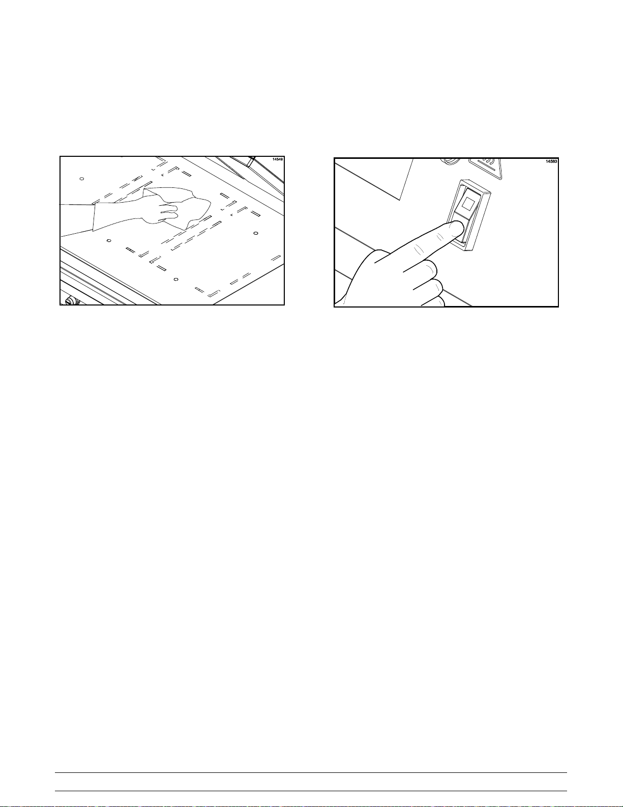
Step 10
Scrape the lower grill surface with the grill scraper,
from front to back.
Figure 51
Step 11
Use the wiper squeegee to push residual grease into
the grease cans.
Step 8
Wash and rinse the clips and retainers in the sink.
Set them aside for future use.
Step 9
Set the release sheets aside on a clean, flat surface
next to the sink until further cleaning is performed.
DO NOT fold, crease, or place them on sharp
objects.
Figure 52
Step 12
Remove, empty, and reinstall the grease cans.
Figure 50
Model 811, 813, 819, 821 Series Operating Procedures
31
Figure 53
120524
Page 36

Step 13
Using a n approved high temperature grill cleaner,
pour approximately 3 oz. (90 ml) onto each 12”
(305 mm) cook zone.
Figure 54
Step 14
Firmly attach the non-abrasive pad to the grill
cleaning pad holder.
Step 17
Apply grill cleaner to the bottom of the platen
handles.
Figure 56
IMPORTANT! Use the grill cleaning pad
and holder identified on page 15 ONLY. Using
any other pad and holder will damage the release
sheets.
Step 15
Dip the pad into the grill cleaner.
IMPORTANT: DO NOT SCRUB while applying
grill cleaner in the following steps:
Step 16
Apply grill cleaner to the front side of the upper
platens.
DO NOT use metal scrapers, abrasive
pads, screens, or wire brushes. Damage to
components may result.
Step 18
Apply grill cleaner to the platen surfaces.
130201
Figure 55
32
Figure 57
Model 811, 813, 819, 821 SeriesOperating Procedures
Page 37

Step 19
Apply grill cleaner to the back side of the upper
platens.
Figure 58
Step 20
Apply grill cleaner to the outer edges of the right and
left platens.
Step 25
Lightly scrub the platen surfaces.
Figure 59
Step 26
Lightly scrub the back side of the upper platens.
Step 21
Press the STANDBY button twice to lower one of the
platens.
811 Only: Press the STANDBY button twice to lower
the center platen. Apply grill cleaner to both sides of
the center platen.
Step 22
Apply grill cleaner to the inner edges of the right and
left platens.
Step 23
Press the RAISE button to raise the lowered platen.
Step 24
Lightly scrub the front side of the platens and the
bottom of the platen handles with the non-abrasive
pad until all soil has been liquified by the grill
cleaner. For stubborn soils, apply additional grill
cleaner and lightly scrub. Do not rinse the platens
at this time.
Figure 60
Step 27
Lightly scrub the outer edges of the right and left
platens.
Step 28
Press the STANDBY button twice to lower one of the
platens.
811 Only: Press the STANDBY button twice to lower
the center platen. Lightly scrub both sides of the
center platen.
Step 29
Lightly scrub the inner edges of the right and left
platens.
Step 30
Press the RAISE button to raise the lowered platen.
Step 31
With a clean, sanitizer-soaked grill cloth, rinse the
front, sides, and back of the platen surfaces.
110610
Model 811, 813, 819, 821 Series Operating Procedures
33
Page 38
Step 32
With a clean, sanitizer-soaked grill cloth, rinse the
bottom of the platen handles, and the front, sides,
and back of the platen surfaces.
Figure 61
Step 33
With a clean, sanitizer-soaked grill cloth, rinse the
platen cook surfaces.
Step 34
Press the STANDBY button twice to lower one of the
platens.
811 Only: Press the STANDBY button twice to lower
the center platen. With a clean, sanitizer-soaked grill
cloth, rinse both sides of the center platen.
Step 35
With a clean, sanitizer-soaked grill cloth, rinse the
inner edges of the right and left platens.
Step 36
Press the RAISE button to raise the lowered platen.
Step 37
With a clean, sanitizer-soaked grill cloth, wipe the
exterior of all the platens, especially behind the rear
of the upper platens (next to the arm assembly).
Step 38
Starting at the back of the lower grill, spread the
remaining grill cleaner over the entire surface. Do
not scrub while applying product.
Step 39
Lightly scrub the surface with the non-abrasive pad
until all soil has been liquified by the grill cleaner.
130201
Figure 62
Figure 63
Note: The rear of the upper platen, as well as the
tubular arm, can easily be wiped from the front of the
unit. If cleaning is performed on a daily basis, there
should be no carbon build-up.
34
Model 811, 813, 819, 821 SeriesOperating Procedures
Page 39

IMPORTANT!
DO NOT use a jet of water to clean or rinse
the grill.
DO NOT use cold water or ice to cool the
upper platen or the lower cook surface.
Failure to follow these instructions may result in:
S serious electrical shock
S burns from hot steam
S liquid collecting inside the grill and
destroying electrical components
S damaged cook surfaces
Step 40
Carefully pour warm water on the lower grill surface,
starting from the back to the front. Use the squeegee
to remove the cleaner from the grill surface.
To avoid damaging the grill:
S Never use grill screens on the upper platen
or the lower grill surface.
S Never use any abrasives or cleaners other
than the approved cleaner.
S Never allow the grill scraper or the abrasive
cleaning materials to come in contact with
the release sheet.
Step 41
Pour a small amount of lukewarm water on a clean,
sanitizer-soaked grill cloth, while holding it over the
lower grill surface. Wipe the lower grill surface until
all residue is removed.
Figure 64
Figure 65
IMPORTANT! Step 42 must be performed
using the grill cleaning pad and holder identified
on page 15 ONLY. Using any other pad and holder
will damage the release sheet.
Note: Contact your local Taylor Distributor to
purchase the correct grill cleaning pad and holder.
(See page 15.)
Model 811, 813, 819, 821 Series Operating Procedures
35
Page 40

Step 42
Place the release sheets flat on the lower grill
surface. Gently clean both sides of the sheets with
an approved high temperature grill cleaner and the
grill cleaning pad and holder.
Figure 66
Step 43
Rinse both sides of the release sheets with a clean,
sanitizer-soaked grill cloth.
Step 46
Remove and empty the grease cans.
Figure 68
Step 47
Wash, rinse, and reinstall the grease cans.
Step 48
Wipe all areas with a clean, sanitizer-soaked grill
cloth.
Step 49
Wipe all exterior panels.
Figure 67
Step 44
Place the release sheets on a clean, sanitized, flat
surfacetoairdryovernight.
Step 45
Wipe the lower grill surface with a clean,
sanitizer-soaked grill cloth. Repeat until no visible
soil remains.
24 Hour Stores Only:
Re-install the release sheets on the opposite side
than previously used. Secure the sheets with the
release sheet clips and retainers. Start up the grill
per instructions starting on page 17.
Figure 69
130107
36
Model 811, 813, 819, 821 SeriesOperating Procedures
Page 41
Non-24 Hour Stores Only:
Step 50
Apply a light coat of vegetable oil to the entire lower
grill surface.
Step 51
Leave the upper platens in the OPEN position
overnight.
Step 52
Place the power switch in the OFF position.
Figure 70
Figure 71
120830
Model 811, 813, 819, 821 Series Operating Procedures
37
Page 42

Section 7 Troubleshooting Guide
PROBLEM PROBABLE CAUSE REMEDY
1. One side of the grill will not
heat. The control will display
the m essage, “PROBE
FAULT”.
2. One heat zone will not heat.
The display reads “TOO
COOL”.
3. One of the heat zones is
overheating. The display reads
“TOO HOT”.
a. One power connection is not
connected.
b. The restaurant circuit breaker
has tripped.
c. The contactor is faulty. c. Call a service technician.
d. The heater is faulty. d. Call a service technician.
e. The high limit switch is faulty. e. Call a service technician.
f. The solid state relay is faulty. f. Call a service technician.
a. The interface board is faulty. a. Call a service technician.
b. The solid state relay is faulty. b. Call a service technician.
c. The control harness is faulty. c. Call a service technician.
a. The interface board is faulty. a. Call a service technician.
a. Check the power connection.
b. Reset the restaurant circuit
breaker.
4. The grill will not turn on when
power switch is placed in the
ON position.
5. The upper platen will not stay
in the STANDBY mode, but will
stay in the COOK position.
120521
b. The solid state relay is faulty. b. Call a service technician.
a. The restaurant circuit breaker
has been tripped.
b. The control cord is not
connected properly.
c. The fuse in the control box is
faulty.
d. The power switch is faulty. d. Call a service technician.
a. Incorrect use of the STANDBY
button.
b. Faulty wire connections. b. Call a service technician.
a. Reset the circuit breaker.
b. Reconnect the cord.
c. Call a service technician.
a. Press STANDBY button within
five seconds of lowering the
platen into the COOK position.
38
Model 811, 813, 819, 821 SeriesTroubleshooting Guide
Page 43

PROBLEM PROBABLE CAUSE REMEDY
6. The upper platen will not stay
in the COOK or STANDBY
position.
7. The upper platen will not stay
in the COOK position, but will
stay in the STANDBY mode.
8. The upper platen opens too
rapidly.
a. Temperature is insufficient to
satisfy the indicator LED's.
b. The control harness is faulty. b. Call a service technician.
c. The interface board is faulty. c. Call a service technician.
d. The latch switch is faulty. d. Call a service technician.
e. The latch solenoid is faulty. e. Call a service technician.
f. The processor control is faulty. f. Call a service technician.
g. The pneumatic system is
faulty.
a. The product is out of
specification.
b. The processor control is not set
properly.
a. The orifice/check valve is
incorrect or missing.
a. Wait until the indicator LED's
turn green.
g. Call a service technician.
a. Product must be within
specification (proper thickness,
shape, etc.).
b. Call a service technician.
a. Call a service technician.
9. The display reads “PLATEN
NOT LATCHED”.
10. The display reads “UPPER
PLATEN STUCK”.
a. The pneumatic system is
faulty.
b. The latch switch is faulty. b. Call a service technician.
c. The latch solenoid is faulty. c. Call a service technician.
a. The arm bearings are dirty. a. Call a service technician.
b. The air cylinder is faulty. b. Call a service technician.
c. Plugged air lines to cylinders. c. Call a service technician.
a. Call a service technician.
120521
Model 811, 813, 819, 821 Series Troubleshooting Guide
39
Page 44

PROBLEM PROBABLE CAUSE REMEDY
11. The platen will not lower to
preset gap height.
12. The product is under-cooked
or overcooked.
a. Excessive carbon build-up on
the shields.
b. Defective motor interface
board.
c. Loose harness connections. c. Call a service technician.
d. Defective main display
controller.
e. Defective motors and cables. e. Call a service technician.
a. The release sheet is worn. a. Replace the release sheet.
b. Incorrect cooking time. b. Reset the processor control for
c. Incorrect temperature setting. c. Adjust the processor control to
d. The upper platen or lower grill
surface is not clean and/or has
carbon build-up.
a. Follow closing procedures to
properly clean and remove
carbon build-up from the
shields.
b. Call a service technician.
d. Call a service technician.
the correct time.
the proper setting.
d. Follow closing procedures to
properly clean the upper platen
and t he lower grill surface and
to remove carbon build-up.
e. There is a grease or carbon
build-up on the bottom of the
upper platen handles.
f. The preset gap height is
incorrect.
g. The heating zone is not
heating.
e. Follow closing procedures to
properly clean and remove
carbon build-up from the
bottom of the platen handles.
f. Call a service technician.
g. Call a service technician.
130201
40
Model 811, 813, 819, 821 SeriesTroubleshooting Guide
Page 45

PROBLEM PROBABLE CAUSE REMEDY
13. The product is not cooking
evenly.
14. The display reads “PROBE
OPEN” and displays the
specific zone.
a. The upper platen or lower grill
surface is not clean and/or has
carbon build-up.
b. There is a grease or carbon
build-up on the bottom of the
upper platen handles.
c. The release sheet is worn. c. Replace release sheet.
d. The product is out of
specification.
e. The platen is not level. e. Call a service technician.
f. The preset gap height is
incorrect.
g. Air pressure is not high
enough.
a. The thermocouple or the
thermocouple interface board
is faulty.
a. Follow closing procedures to
properly clean the upper platen
and t he lower grill surface and
to remove carbon build-up.
b. Follow closing procedures to
properly clean and remove
carbon build-up from the
bottom of the platen handles.
d. Product must be within
specification (proper thickness,
shape, etc.).
f. Call a service technician.
g. Call a service technician.
a. Call a service technician.
15. The display reads “HOME
SWITCH STUCK ON.”
16. The display reads “HOME
SWITCH NOT SEEN.”
a. Two sided cooking options are
blocked.
b. Defective stepper motor. b. Call a service technician.
c. Defective stepper motor wire
harness.
d. Defective home switch. d. Call a service technician.
e. Defective motor control. e. Call a service technician.
a. Defective motor control. a. Call a service technician.
b. Defective stepper motor. b. Call a service technician.
c. Defective stepper motor wire
harness.
d. Defective home switch. d. Call a service technician.
e. Broken platen cable. e. Call a service technician.
a. Turn the control off and then
back on to clear the fault.
c. Call a service technician.
c. Call a service technician.
130201
Model 811, 813, 819, 821 Series Troubleshooting Guide
41
Page 46

GAS ZONES ONLY
PROBLEM
1. The display reads “BLOWER
FAILURE”.
2. The burner will not light. The
display reads “IGNITION
FAILURE”.
PROBABLE CAUSE REMEDY
a. The blower is faulty. a. Call a service technician.
b. The pressure switch is faulty. b. Call a service technician.
a. The quick disconnect gas hose
is not fully engaged.
b. The manual shutoff valve is in
the OFF position.
c. Air is in the gas hose. c. Wait 5 minutes before
d. The processor control is faulty. d. Call a service technician.
e. The spark ignition module is
faulty.
f. The gas solenoid is faulty. f. Call a service technician.
g. The electrode is faulty. g. Call a service technician.
h. The interface board is faulty. h. Call a service technician.
a. Re-engage the quick
disconnect.
b. Turn the valve to the ON
position.
relighting.
e. Call a service technician.
3. The burner lights but will not
stay lit.
4. The burner lights but the zone
is cool or overheats.
a. The electrode is faulty. a. Call a service technician.
b. Improper ground. b. Call a service technician.
a. The grill is out of calibration. a. Call a service technician.
b. The processor control is faulty. b. Call a service technician.
c. The thermocouple is faulty. c. Call a service technician.
42
Model 811, 813, 819, 821 SeriesTroubleshooting Guide
Page 47

Section 8 Limited Warranty on Equipment
TAYLOR COMPANY LIMITED WARRANTY ON CROWN SERIES GRILLS
Taylor Company, a division of Carrier Commercial Refrigeration, Inc. (“Taylor”) is pleased to provide this limited
warranty on new Taylor-branded Crown Series g rill equipment available from Taylor to the market generally (the
“Product”) to the original purchaser only.
LIMITED WARRANTY
Taylor warrants the Product against failure due to defect in materials or workmanship under normal use and
service a s follows. All warranty periods begin on the date of original Product installation. If a part fails due to
defect during the applicable warranty period, T aylor, through an authorized Taylor distributor or service agency,
will provide a new or re-manufactured part, at Taylor’s option, to replace the failed defective part at no charge for
the part. Except as otherwise stated herein, these are Taylor’s exclusive obligations under this limited warranty for
a Product failure. This limited warranty is subject to all provisions, conditions, limitations and exclusions listed
below and on the reverse (if any) of this document.
Product
Taylor Crown Series Grills
1. If the date of original installation of the Product cannot be verified, then the limited warranty period begins
ninety (90) days from the date of Product manufacture (as indicated by the Product serial number). Proof of
purchasemayberequiredattimeofservice.
2. This limited warranty is valid only if the Product is installed and all required service work on the Product is
performed by an authorized Taylor distributor or service agency, and only if genuine, new Taylor parts are
used.
3. Installation, use, care, and maintenance must b e normal and in accordance with all instructions contained in
the T aylor Operator’s Manual.
4. Defective parts must be returned to the authorized Taylor distributor or service agency for credit.
This limited warranty does not
Air compressor (excluding tank, solenoid, pressure
switch, check valve, air cylinder, fittings, and airline)
The upper platen’s aluminum casting and shroud
only, and excluding all other upper platen
components, including those internal to the upper
platen
Microprocessor control Three (3) years
Partsnototherwiselistedinthistableorexcluded
below
LIMITED WARRANTY CONDITIONS
LIMITED WARRANTY EXCEPTIONS
cover:
Part Limited Warranty Period
Two (2) years
Two (2) years
One (1) year
1. Labor or other costs incurred for diagnosing, repairing, removing, installing, shipping, servicing or handling of
defective parts, replacement parts, or new Products.
2. Normal maintenance and cleaning as outlined in the Taylor Operator’s Manual, including cleaning of carbon
and grease buildup.
3. Required service, whether cleaning or general repairs, to return the Product’s cooking surface assemblies,
including the upper platen and lower plate, to an operational condition to achieve proper cooking or allow
proper assembly of release sheets and clips as a result of grease build-up on the cooking surfaces, including
but not limited to the platen and plate, sides of the shroud or top of the shroud.
131205
Model 811, 813, 819, 821 Series Limited Warranty on Equipment
43
Page 48

4. Replacement of the Product’s cooking surfaces, including the upper platen and lower plate, due to pitting or
corrosion (or in the case of the upper platen, due to loss of plating) as a result of damage due to the impact
of spatulas or other small wares used during the cooking process or as a result of the use of cleaners,
cleaning materials or cleaning processes not approved for use by Taylor.
5. Replacement of wear items designated as Class “000” parts in the Taylor Operator’s Manual, as well as any
release sheets and clips.
6. External hoses, electrical power supplies, and machine grounding.
7. Parts not supplied or designated by Taylor, or damages resulting from their use.
8. Return trips or waiting time required because a service technician is prevented from beginning warranty
service work promptly upon arrival.
9. Costs incurred to address food safety issues when the technician determines food safety standards are met
and the Product gaps are within specification.
10. Failure, damage or repairs due to faulty installation, misapplication, abuse, no or improper servicing,
unauthorized alteration or improper operation or use as indicated in the Taylor Operator’s Manual, including
but not limited to the failure to use proper assembly and cleaning techniques, tools, or approved cleaning
supplies .
11. Failure, damage or repairs due to theft, vandalism, wind, rain, flood, high water, water, lightning, earthquake
or any other natural disaster, fire, corrosive environments, insect or rodent infestation, or other casualty,
accident or condition beyond the reasonable control of Taylor; operation above or below the electrical or gas
specification of the Product; or components repaired or altered in any way so as, in the judgment of the
Manufacturer, to adversely affect performance, or normal wear or deterioration.
12. Any Product purchased over the Internet.
13. Failure to start due to voltage conditions, blown fuses, open circuit breakers, or damages due to the
inadequacy or interruption of electrical or gas service.
14. Electricity, gas or other fuel costs, or increases in electricity, gas or other fuel costs from any reason
whatsoever.
15. ANY SPECIAL, INDIRECT OR CONSEQUENTIAL PROPERTY OR COMMERCIAL DAMAGE OF ANY
NATURE WHATSOEVER. Some jurisdictions do not allow the exclusion of incidental or consequential
damages, so this limitation may not apply to you.
This limited warranty gives you specific legal rights, and you may also have other rights which vary from
jurisdiction to jurisdiction.
44
Model 811, 813, 819, 821 SeriesLimited Warranty on Equipment
Page 49

LIMITATION OF WARRANTY
THIS LIMITED WARRANTY IS EXCLUSIVE AND IS IN LIEU OF ALL OTHER WARRANTIES, CONDITIONS
AND/OR REMEDIES UNDER THE LAW, INCLUDING ANY IMPLIED WARRANTIES OR CONDITIONS OF
MERCHANTABILITY OR FITNESS FOR A PARTICULAR PURPOSE. THE ORIGINAL OWNER'S SOLE
REMEDY WITH RESPECT TO ANY PRODUCTS SHALL BE REPAIR OR REPLACEMENT OF DEFECTIVE
COMPONENTS UNDER THE TERMS OF THIS LIMITED WARRANTY. ALL RIGHTS TO CONSEQUENTIAL
OR INCIDENTAL DAMAGES (INCLUDING CLAIMS FOR LOST SALES, LOST PROFITS, PRODUCT LOSS,
PROPERTY DAMAGES OR SERVICE EXPENSES) ARE EXPRESSLY EXCLUDED. THE EXPRESS
WARRANTIES MADE IN THIS LIMITED WARRANTY MAY NOT BE ALTERED, ENLARGED, OR CHANGED
BY ANY DISTRIBUTOR, DEALER, OR OTHER PERSON, WHATSOEVER.
LEGAL REMEDIES
The owner must notify Taylor in writing, by certified or registered letter to the following address, of any defect or
complaint with the Product, stating the defect or complaint and a specific request for repair, replacement, or other
correction of the Product under warranty, mailed at least thirty (30) days before pursuing a ny legal rights or
remedies.
Taylor Company
a division of Carrier Commercial Refrigeration, Inc.
750 N. Blackhawk Blvd.
Rockton, IL 61072, U.S.A.
Model 811, 813, 819, 821 Series Limited Warranty on Equipment
45
Page 50

Section9 LimitedWarrantyonParts
TAYLOR COMPANY LIMITED WARRANTY ON TAYLOR GENUINE PARTS
Taylor Company, a division of Carrier Commercial Refrigeration, Inc. (“Taylor”) is pleased to provide this limited
warranty on new Taylor genuine replacement components and parts available from Taylor to the market generally
(the “Parts”) to the original purchaser only.
LIMITED WARRANTY
Taylor warrants the Parts against failure due to defect in materials or workmanship under normal use and service
as follows. All warranty periods begin on the date of original installation of the Part in the Taylor unit. If a Part fails
due to defect during the applicable warranty period, Taylor, through an authorized Taylor distributor or service
agency, will provide a new or re-manufactured Part, at Taylor’s option, to replace the failed defective Part at no
charge for the Part. Except as otherwise stated herein, these are Taylor’s exclusive obligations under this limited
warranty for a Part failure. This limited warranty is subject to all provisions, conditions, limitations and exclusions
listed below and on the reverse (if any) of this document.
Part's Warranty Class Code or Part
Class 103 Parts¹ Three (3) months
Class 212 Parts² Twelve (12) months
Class 512 Parts Twelve (12) months
Class 000 Parts No warranty
Taylor Part #072454 (Motor-24VDC *C832/C842*) Four (4) years
LIMITED WARRANTY CONDITIONS
1. If the date of original installation of the Part cannot be otherwise verified, proof of purchase may be required
at time of service.
2. This limited warranty is valid only if the Part is installed and all required service work in connection with the
Part is performed by an authorized Taylor distributor or service agency.
3. The limited warranty applies only to Parts remaining in use by their original owner at their original installation
location in the unit of original installation.
4. Installation, use, care, and maintenance must be normal and in accordance with all instructions contained in
the Taylor Operator’s Manual.
5. Defective Parts must be returned to the authorized Taylor distributor or service agency for credit.
6. This warranty is not intended to shorten the length of any warranty coverage provided pursuant to a separate
Taylor Limited Warranty on freezer or grill equipment.
Limited Warranty Period
7. The use of any refrigerant other than that specified for the unit in which the Part is installed will void this
limited warranty.
1, 2
Except that Taylor Part #032129SER2 (Compressor-Air-230V SERV) and Taylor Part #075506SER1
(Compressor-Air-115V 60HZ) shall have a limited warranty period of twelve (12) months when used in Taylor
freezer equipment and a limited warranty period of two (2) years when used in Taylor grill equipment.
131205
46
Model 811, 813, 819, 821 SeriesLimited Warranty on Parts
Page 51

LIMITED WARRANTY EXCEPTIONS
This limited warranty does not
cover:
1. Labor or other costs incurred for diagnosing, repairing, removing, installing, shipping, servicing or handling of
defective Parts, replacement Parts, or new Parts.
2. Normal maintenance, cleaning and lubrication as outlined in the Taylor Operator’s Manual, including cleaning
of condensers or carbon and grease buildup.
3. Required service, whether cleaning or general repairs, to return the cooking surface assemblies, including
the upper platen and lower plate, to an operational condition to achieve proper cooking or allow proper
assembly of release sheets and clips as a result of grease build-up on the cooking surfaces, including but not
limited to the platen and plate, sides of the shroud or top of the shroud.
4. Replacement of cooking surfaces, including the upper platen and lower plate, due to pitting or corrosion (or in
the case of the upper platen, due to loss of plating) as a result of damage due to the impact of spatulas or
other small wares used during the cooking process or as a result of the use of cleaners, cleaning materials or
cleaning processes not approved for use by Taylor.
5. Replacement of wear items designated as Class “000” Parts in the Taylor Operator’s Manual, as well as any
release sheets and clips for the Product’s upper platen assembly.
6. External hoses, electrical power supplies, and machine grounding.
7. Parts not supplied or designated by Taylor, or damages resulting from their use.
8. Return trips or waiting time required because a service technician is prevented from beginning warranty
service work promptly upon arrival.
9. Failure, damage or repairs due to faulty installation, misapplication, abuse, no or improper servicing,
unauthorized alteration or improper operation or u se as indicated in the Taylor Operator’s Manual, including
but not limited to the failure to use proper assembly and cleaning techniques, tools, or approved cleaning
supplies.
10. Failure, damage or repairs due to theft, vandalism, wind, rain, flood, high water, water, lightning, earthquake
or any other natural disaster, fire, corrosive environments, insect or rodent infestation, or other casualty,
accident or condition beyond the reasonable control of Taylor; operation above or below the gas, electrical or
water supply specification of the unit in which a part is installed; or Parts or the units in which they are
installed repaired or altered in any way so as, in the judgment of Taylor, to adversely affect performance, or
normal wear or deterioration.
11. Any Part purchased over the Internet.
12. Failure to start due to voltage conditions, blown fuses, open circuit breakers, or damages due to the
inadequacy or interruption of electrical service.
13. Electricity, gas or other fuel costs, or increases in electricity or fuel costs from any reason whatsoever.
14. Damages resulting from the use of any refrigerant other than that specified for the unit in which the Part is
installed will void this limited warranty.
15. Any cost to replace, refill or dispose of refrigerant, including the cost of refrigerant.
16. ANY SPECIAL, INDIRECT OR CONSEQUENTIAL PROPERTY OR COMMERCIAL DAMAGE OF ANY
NATURE WHATSOEVER. Some jurisdictions do not allow the exclusion of incidental or consequential
damages, so this limitation may not apply to you.
This limited warranty gives you specific legal rights, and you may also have other rights which vary from
jurisdiction to jurisdiction.
Model 811, 813, 819, 821 Series Limited Warranty on Parts
47
Page 52

LIMITATION OF WARRANTY
THIS LIMITED WARRANTY IS EXCLUSIVE AND IS IN LIEU OF ALL OTHER WARRANTIES, CONDITIONS
AND/OR REMEDIES UNDER THE LAW, INCLUDING ANY IMPLIED WARRANTIES OR CONDITIONS OF
MERCHANTABILITY OR FITNESS FOR A PARTICULAR PURPOSE. THE ORIGINAL OWNER'S SOLE
REMEDY WITH RESPECT TO ANY PRODUCTS SHALL BE REPAIR OR REPLACEMENT OF DEFECTIVE
PARTS UNDER THE TERMS OF THIS LIMITED WARRANTY. ALL RIGHTS TO CONSEQUENTIAL OR
INCIDENTAL DAMAGES (INCLUDING CLAIMS FOR LOST SALES, LOST PROFITS, PRODUCT LOSS,
PROPERTY DAMAGES OR SERVICE EXPENSES) ARE EXPRESSLY EXCLUDED. THE EXPRESS
WARRANTIES MADE IN THIS LIMITED WARRANTY MAY NOT BE ALTERED, ENLARGED, OR CHANGED
BY ANY DISTRIBUTOR, DEALER, OR OTHER PERSON, WHATSOEVER.
LEGAL REMEDIES
The owner must notify Taylor in writing, by certified or registered letter to the following address, of any defect or
complaint with the Part, stating the defect or complaint and a specific request for repair, replacement, or o ther
correction of the Part under warranty, mailed at least thirty (30) days before pursuing any legal rights or remedies.
Taylor Company
a division of Carrier Commercial Refrigeration, Inc.
750 N. Blackhawk Blvd.
Rockton, IL 61072, U.S.A.
48
Model 811, 813, 819, 821 SeriesLimited Warranty on Parts
Page 53
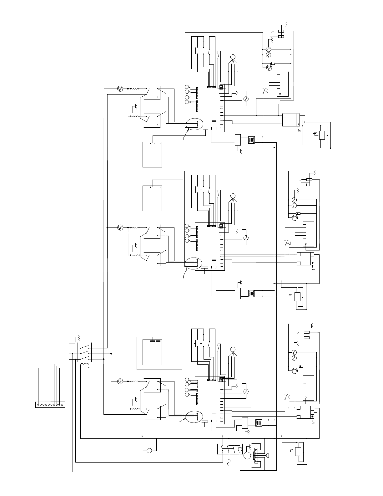
ELECTRODE
BLK/WHT
BLK/WHT
BLK/WHT
RAISE
STANDBY
LATCH
BLK
WHT/BLU
BLK/YEL
PUR
THM
OVLD
L1
RED
L3
WHT
BLK
2
1300W
BLK
BLK
GRN/YEL
BLK
1300W
L1
L3
3+
SSR
1
RTF
4
2
3+
SSR
1
RTR
4
J4
J3
BOARD
DISPLAY
CONTROL-
BRN
ORN
BRN
PUR
RTR
#4
TOP
YEL
+
RED
-
REARFRONT
REAR
YEL
+
RR
#3
RED
-
MID
+
-
FRONT
YEL
+
RED
RF
#1
-
TOP
+
YEL
-
RED
RTF
#5
BRN
ORN
DETAIL A
BOARD
12V
TOP FRT HTR
TOP REAR HTR
MID HTR
FT HTR
CONTROL-MOTOR
BK HTR
J4
J5
24VAC
M
YEL
ORG
RED
BLK
BLU
RED
WHT
GRN
BLK
RED
45
12
6
3
J3
J1
GND
+
LATCH
PLATEN
-
HOOD FAN
-GND
+OUT
+IN
OUT
IN
ORN/WHT
ORN
DC IDC
ORN
AC IDC
ORN/WHT
ORN
F-EMI
GRN/YEL
PUR
GRN/YEL
GAS
SOLENOID
WHT
SEE
DIODE
NOTE 1
THM
OVLD
12VDC
WHT
ORN
SWITCH
PRP
PRESSURE
LATCH
SOLENOID
TAN
BLK/BLU
BLU/WHT
WHT
BLU
GV
GND
NOTE: 1.) DIODE MUST BE INSTALLED WITH IDENTIFICATION STRIPE ON "+" SIDE
ORN/WHT
12VDC
L
N
SUPPLY
GRN/YEL
OF GAS VALVES.
BLK
GRY
GRY
BLU
BRN
GRN/YEL
BLK
BLOWER
ORN
PRP
COM
ORN/WHT
IDC
+
BLK
GRY
ELECTRODE
BLK/WHT
BLK/WHT
BLK/WHT
J4
J3
BOARD
DISPLAY
CONTROL-
THM
OVLD
L3
L2
RED
WHT
2
1300W
BLK
1
BLK
GRN/YEL
BLK
2
1300W
L3
L2
1
SSR
SSR
3+
MTF
4
3+
MTR
4
BRN
ORG
BRN
YEL
MTR
MR
MF
MTF
BRN
ORG
RAISE
STANDBY
LATCH
BLK
WHT/BLU
BLK/YEL
#4
TOP
YEL
+
RED
-
REARFRONT
REAR
YEL
+
#3
RED
-
MID
+
-
FRONT
YEL
+
#1
RED
-
TOP
+
YEL
-
RED
#5
BOARD
12V
TOP FRT HTR
TOP REAR HTR
MID HTR
FT HTR
CONTROL-MOTOR
BK HTR
J4
YEL
J5
24VAC
M
YEL
ORG
RED
BLK
BLU
RED
WHT
GRN
BLK
RED
45
12
6
3
J3
J1
GND
+
LATCH
PLATEN
-
HOOD FAN
+OUT-GND
DC IDC
+IN
OUT
AC IDC
IN
PRP
LATCH
SOLENOID
TAN
BRN/WHT
BRN
BRN
BRN
SWITCH
PRESSURE
YEL
GRN/YEL
GAS
SOLENOID
WHT
SEE
DIODE
NOTE 1
THM
OVLD
12VDC
WHT
GV
GND
COM
BRN/WHT
BRN/WHT
IDC
L
+
12VDC
SUPPLY
GRN/YEL
BLK
N
GRY
208 VAC
TAN
ORN
BLU, YEL, OR PRP PER CONTROL BOARD
BLU, YEL, OR PRP PER CONTROL BOARD
BK HTR
FT HTR
12V
MID HTR
TOP FRT HTR
TOP REAR HTR
J4
GND
C1
L2 L3
L1
BLK
DETAIL A
DETAIL A
BRN/WHT
BRN
GRN/YEL
F-EMI
BLK
BLK/BLU
BLU/WHT
WHT
BLU
GRY
GRY
BLU
BRN
GRN/YEL
BLK
BLOWER
ORN
PRP
ELECTRODE
BLK/WHT
BLK/WHT
BLK/WHT
J4
L1
1300W
1300W
L1
BLK
RED
BLK
BLK
GRY
J3
BOARD
DISPLAY
4
CONTROL-
2
3+
SSRSSR
1
LTFLTR
4
2
3+
1
4
BLK
M
BLU
BRN
ORN
BRN
BLU
LTR
LR
LF
LTF
BRN
ORN
DETAIL A
BLK
BLK
BLK
GRY
WHT
THM
OVLD
L2
GRN
L2
RAISE
STANDBY
LATCH
BLK
WHT/BLU
BLK/YEL
#4
TOP
YEL
+
RED
-
REARFRONT
REAR
YEL
+
#3
RED
-
MID
+
-
FRONT
YEL
+
#1
RED
-
TOP
+
YEL
-
RED
#5
BOARD
12V
TOP FRT HTR
TOP REAR HTR
MID HTR
FT HTR
CONTROL-MOTOR
BK HTR
J4
J5
24VAC
M
YEL
ORG
RED
BLK
BLU
RED
WHT
GRN
BLK
RED
45
12
6
3
J3
J1
GND
+
LATCH
PLATEN
-
HOOD FAN
-GND
+OUT
DC IDC
+IN
OUT
AC IDC
IN
GRY
3
6
5
GRY/BLK
2
BLK/WHT
PRP
LATCH
SOLENOID
TAN
BLU/WHT
BLU/WHT
BLU
GRN/YEL
BLK
AMB
7
4A
GRY
BLK
F-EMI
GRN/YEL
AIR
COMP
BLU
BLU/WHT
BLU
BLU
BLK/BLU
WHT
GRY
BLK
WHT BLK
BLU
GRN/YEL
GAS
SOLENOID
WHT
SEE
DIODE
NOTE 1
THM
OVLD
12VDC
WHT
BLU/WHT
GRN/YEL
BLU
PRP
+
BLOWER
BRN
ORN
12VDC
BLK
GV
GND
COM
SUPPLY
GRN/YEL
IDC
L
N
BLU/WHT
GRY
BLK
811
073475-23
BLU
SWITCH
PRESSURE
BLK
GRY
GRY
GRY
11/18/13
Page 54
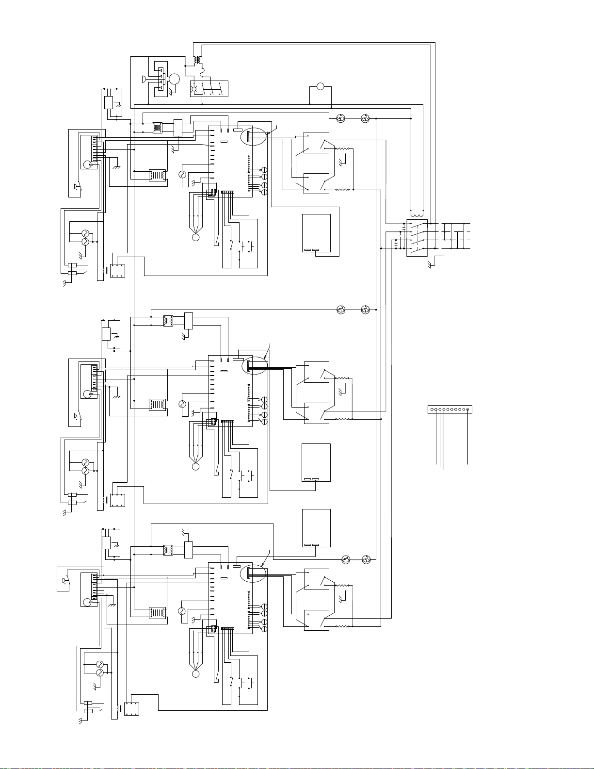
WHT/ORG
WHT
BLK
WHT BLK
COMP
GRY
ORN
PRP
BLOWER
BRN
PRP
GRN/YEL
BRN
BLU
WHT
GRY
WHT
BLK/BLU
TH/W
PSW
V1
YEL
IND/V1
L1
R
V2
WHT/ORG
GND
S1
ORG
PRESSURE
SWITCH
SOLENOID
GAS
BLU
WHT
BLK
GRN/YEL
BRN
14
13
ELECTRODE
PRP
BLOWER
PRP
BLU
TH/W
PSW
V1
YEL
IND/V1
L1
R
V2
WHT/ORG
GND
S1
ORG
PRESSURE
SWITCH
SOLENOID
GAS
BLU
WHT
GRN/YEL
BLK
BRN
14
13
ELECTRODE
PRP
BLOWER
PRP
BLU
ORG
PRESSURE
SWITCH
TH/W
PSW
V1
YEL
IND/V1
L1
R
V2
GND
S1
SOLENOID
GAS
GRN/YEL
WHT
BLK
ELECTRODE
BLK
BLK
GRN/YEL
BLU
BLU
12
4
8
1
9
5
ORN
GRN/YEL
BRN
YEL
12
9
ORN
GRN/YEL
BRN
GRN/YEL
BRN
14
13
GRY
BLK
BRN
WHT
BLK
GRN/YEL
YEL
4
8
1
5
BRN
GRY
BLK
WHT
BLK
BLU
PUR
PUR
12
4
8
1
9
5
AIR
GRN/YEL
AMB
BLK
GRY
F-EMI
BLU
BLU
BLU/WHT
BLU/WHT
WHT/ORG
BLU
GRN/YEL
TAN
SOLENOID
LATCH
PRP
10 VA MIN
WHT
GRN
BLU
YEL
M
WHT
BLK/BLU
10 VA MIN
LATCH
BLU/WHT
SOLENOID
BRN
BRN/WHT
GRN/YEL
WHT/ORG
TAN
PRP
WHT
GRN
BLU
YEL
F-EMI
BLU
M
GRN/YEL
F-EMI
BLU
WHT
BLK/BLU
10 VA MIN
BLU/WHT
SOLENOID
LATCH
ORN
ORN/WHT
WHT/ORG
TAN
PRP
WHT
GRN
BLU
YEL
M
24VAC
J5
IN
YEL
AC IDC
OUT
+IN
DC IDC
+OUT
-GND
HOOD FAN
-
PLATEN
LATCH
+
GND
J1
3
6
12
45
BLK
RED
BLK
RED
ORG
IN
YEL
AC IDC
OUT
+IN
DC IDC
+OUT
YEL
-GND
HOOD FAN
-
PLATEN
LATCH
+
GND
J1
3
6
12
45
BLK
RED
BLK
RED
ORG
IN
YEL
AC IDC
OUT
+IN
DC IDC
+OUT
PUR
-GND
HOOD FAN
-
PLATEN
LATCH
+
GND
J1
3
6
12
45
BLK
RED
BLK
RED
ORG
BK HTR
CONTROL-MOTOR
FT HTR
MID HTR
TOP REAR HTR
TOP FRT HTR
12V
BOARD
J3
REARFRONT
RED
BLK/YEL
WHT/BLU
LATCH
STANDBY
RAISE
BLK/WHT
BLK/WHT
24VAC
J5
BK HTR
CONTROL-MOTOR
FT HTR
MID HTR
TOP REAR HTR
TOP FRT HTR
12V
BOARD
J3
REARFRONT
RED
BLK/YEL
WHT/BLU
LATCH
STANDBY
RAISE
BLK/WHT
BLK/WHT
24VAC
J5
BK HTR
CONTROL-MOTOR
FT HTR
MID HTR
TOP REAR HTR
TOP FRT HTR
12V
BOARD
J3
REARFRONT
RED
BLK/YEL
WHT/BLU
LATCH
STANDBY
RAISE
BLK/WHT
BLK/WHT
DETAIL A
J4
ORN
BRN
LTF
#5
RED
-
YEL
+
TOP
-
RED
LF
#1
+
YEL
FRONT
+
MID
-
RED
LR
#3
+
YEL
REAR
-
RED
+
YEL
TOP
LTR
#4
BLU
BLK
BLK/WHT
DETAIL A
YEL
J4
ORG
BRN
MTF
#5
RED
-
YEL
+
TOP
-
RED
MF
#1
+
YEL
FRONT
+
MID
-
RED
MR
#3
+
YEL
REAR
-
RED
+
YEL
TOP
MTR
#4
BLK
BLK/WHT
DETAIL A
J4
ORN
BRN
RTF
#5
RED
-
YEL
+
TOP
-
RF
#1
RED
+
YEL
FRONT
+
MID
-
RED
RR
#3
+
YEL
REAR
-
RED
+
YEL
TOP
RTR
#4
PUR
BLK
BLK/WHT
M
BLK
GRY
GRY
BLU
BLU
LWR
THM
OVLD
4
BLU
1
L1
3+
2
BLK
4
LTFLTR
SSRSSR
3+
DISPLAY
BOARD
J3
J4
4
MTR
SSR
3+
4
MTF
SSR
3+
DISPLAY
BOARD
J3
J4
DISPLAY
BOARD
J3
J4
4
RTR
SSR
3+
4
RTF
SSR
3+
BLK
1
2
RED
L1
CONTROL-
GRY
OVLD
1
L2
2
BLK
BLK
1
2
RED
L2
CONTROL-
CONTROL-
GRY
1
L3
2
BLK
BLK
1
2
L3
RED
BRN
ORN
BRN
4
YEL
BRN
ORG
BRN
PUR
BRN
ORN
BRN
THM
OVLD
BLK
N
1300W
GRN
1300W
N
BLU
BLU
THM
OVLD
LWR
THM
N
1300W
GRN/YEL
TGGT
BLK
1300W
N
BLU
BLU
THM
OVLD
LWR
THM
OVLD
N
1300W
GRN/YEL
BLK
1300W
GRY
BLK
C1
DETAIL A
12V
L1
400
VAC
400 VAC
L2 L3
230 VAC
400
VAC
230 VAC
230
VAC
N
GND
TOP REAR HTR
TOP FRT HTR
MID HTR
FT HTR
BK HTR
J4
TAN
BLU, YEL, OR PRP PER CONTROL BOARD
ORN
BLU, YEL, OR PRP PER CONTROL BOARD
BLK
BLK
BLK
811
073475-75
11/18/13
Page 55
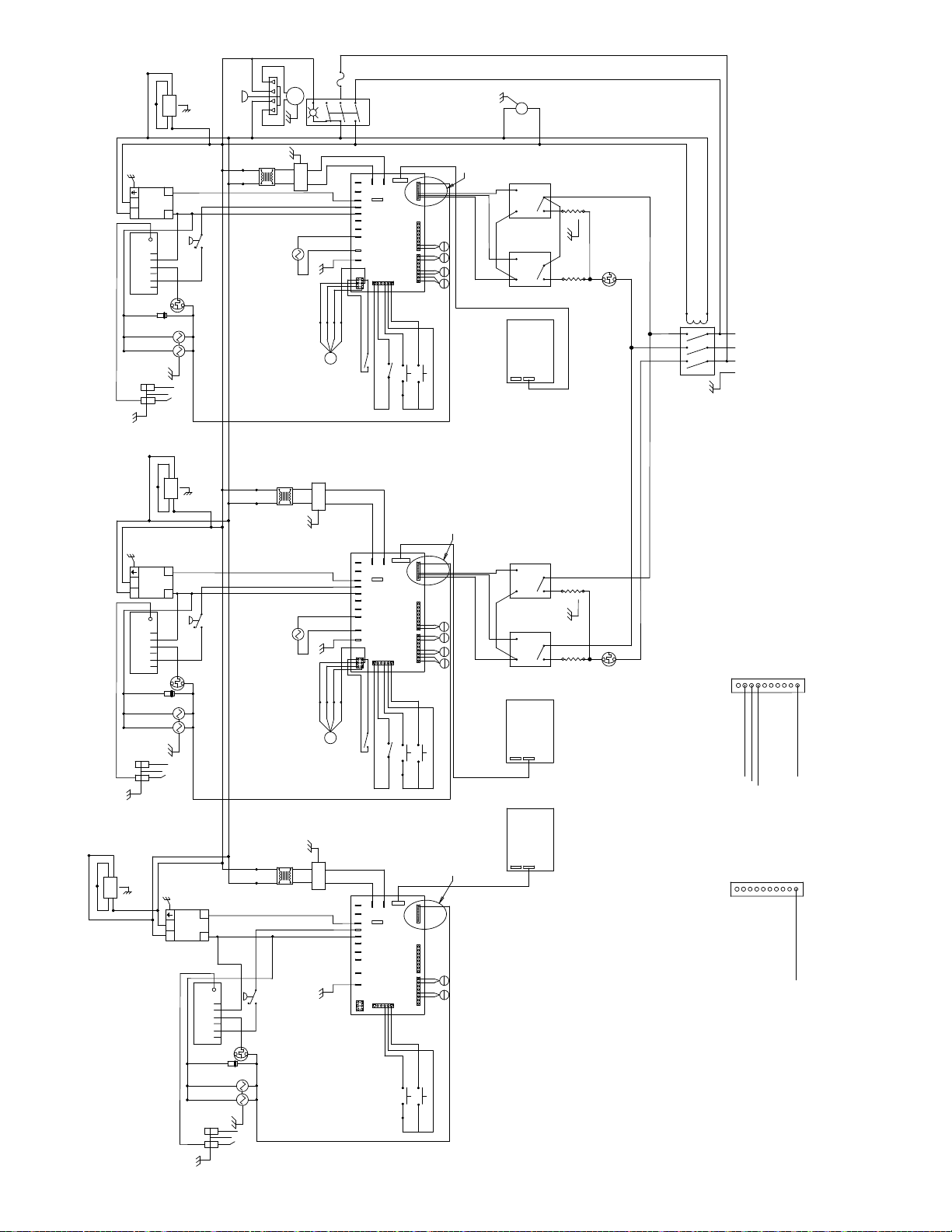
AIR
GRN/YEL
GRN/YEL
F-EMI
TAN
PRP
BLU/WHT
AMB
BLU/WHT
BLK
GRY
4A
GRY/BLK
BLK/WHT
7
5
2
6
3
BLK
GRY
+
+
+
+
+
BLK
BLK/WHT
DETAIL A
BRN
LTF
#5
RED
YEL
TOP
RED
LF
#1
YEL
FRONT
MID
RED
LR
#3
YEL
REAR
RED
YEL
TOP
LTR
#4
BLU
BLU
WHT
GRN
BLK
BLU
ORG
YEL
M
IN
AC IDC
OUT
+IN
DC IDC
+OUT-GND
HOOD FAN
-
PLATEN
LATCH
+
GND
J1
3
6
12
45
RED
BLK
RED
24VAC
J5
J4
BK HTR
CONTROL-MOTOR
FT HTR
MID HTR
TOP REAR HTR
TOP FRT HTR
12V
BOARD
J3
REARFRONT
RED
BLK/YEL
WHT/BLU
LATCH
STANDBY
RAISE
BLK/WHT
BLK/WHT
M
BLK
GRY
4
BLU
1
BLK
L1
3+
ORN
BRN
4
ORN
LTFLTR
SSRSSR
3+
BRN
4
DISPLAY
BOARD
J3
J4
1300W
2
BLK
BLK
1
1300W
2
RED
L1
CONTROL-
L2
GRN
L2
THM
OVLD
WHT
GRY
BLK
BLK
BLK
BLK
L1
208 VAC
L2 L3
C1
GND
WHT BLK
PRP
ORN
BLOWER
BLK
GRN/YEL
BRN
BLU
GRN/YEL
12VDC
SUPPLY
GRY
+
N
BLK
-
L
IDC
BLU/WHT
COM
GND
GV
12VDC
NOTE 1
DIODE
SEE
SOLENOID
GAS
BLU/WHT
WHT
GRN/YEL
GRY
GRY
GRY
WHT
BLK
PRESSURE
SWITCH
BLU
THM
OVLD
WHT
BLU
BLK/BLU
COMP
BLK
GRY
BLU
BLU/WHT
BLU
BLU
SOLENOID
LATCH
ELECTRODE
PRP
ORN
BLOWER
BLK
GRN/YEL
BRN
BLU
GRY
GRY
WHT
BLK/BLU
BLK
BLU/WHT
F-EMI
BLU
BRN
BRN/WHT
GRN/YEL
DETAIL A
GRN/YEL
12VDC
SUPPLY
GRY
+
N
BLK
BRN/WHT
L
IDC
-
PRESSURE
SWITCH
BRN/WHT
COM
GND
GV
12VDC
NOTE 1
DIODE
BRN
WHT
THM
OVLD
SEE
WHT
SOLENOID
GAS
GRN/YEL
YEL
SOLENOID
LATCH
BRN
BRN
BRN/WHT
TAN
PRP
WHT
GRN
BLK
BLU
ORG
YEL
M
IN
AC IDC
OUT
+IN
DC IDC
+OUT-GND
HOOD FAN
-
PLATEN
LATCH
+
GND
J1
3
6
12
45
RED
BLK
RED
24VAC
J5
J4
BK HTR
CONTROL-MOTOR
FT HTR
MID HTR
TOP REAR HTR
TOP FRT HTR
12V
BOARD
+
+
+
+
J3
REARFRONT
+
RED
BLK/YEL
WHT/BLU
BLK
LATCH
STANDBY
RAISE
BLK/WHT
BLK/WHT
BLK/WHT
YEL
MTF
#5
RED
YEL
TOP
RED
MF
#1
YEL
FRONT
MID
RED
MR
#3
YEL
REAR
RED
YEL
TOP
MTR
#4
4
YEL
MTR
1
SSR
BLK
L1
3+
ORG
BRN
BRN
4
ORG
MTF
SSR
3+
BRN
DISPLAY
BOARD
J3
J4
1300W
2
BLK
1
1300W
2
RED
L2
CONTROL-
GRN/YEL
L3
TOP REAR HTR
TOP FRT HTR
MID HTR
FT HTR
WHT
L3
THM
OVLD
DETAIL A
BK HTR
12V
TAN
ORN
BLU, YEL, PER CONTROL BOARD
J4
BLU, YEL, PER CONTROL BOARD
ELECTRODE
CONTROL-
DISPLAY
BOARD
TOP REAR HTR
DETAIL B
12V
TOP FRT HTR
MID HTR
FT HTR
BK HTR
J4
PRP
073725-23
813
GRN/YEL
PRP
ORN
BLOWER
BLK
GRN/YEL
BRN
BLU
GRN/YEL
GRY
12VDC
SUPPLY
GRY
N
BLK
L
IDC
ORN/WHT
NOTE: 1.) DIODE MUST BE INSTALLED WITH IDENTIFICATION STRIPE ON "+" SIDE
OF GAS VALVES.
GRY
WHT
BLK/BLU
BLK
+
-
PRESSURE
ORN/WHT
SWITCH
COM
GND
GV
12VDC
NOTE 1
DIODE
ORN
WHT
THM
OVLD
SEE
WHT
SOLENOID
GAS
BLU/WHT
F-EMI
BLU
ORN
ORN/WHT
24VAC
J5
ORN
ORN
ORN/WHT
AC IDC
+IN
DC IDC
+OUT-GND
BOARD
HOOD FAN
-
PLATEN
LATCH
+
GND
J1
J3
3
6
12
45
CONTROL-MOTOR
RAISE
GRN/YEL
PUR
WHT/BLU
BLK/WHT
J4
BK HTR
FT HTR
MID HTR
TOP REAR HTR
TOP FRT HTR
12V
REARFRONT
STANDBY
DETAIL B
+
TOP
-
RF
#1
RED
+
YEL
FRONT
+
MID
-
RED
RR
#3
+
YEL
REAR
+
TOP
PUR
BLK
BLK/WHT
J3
J4
ELECTRODE
11/18/13
Page 56

F-EMI
TAN
PRP
BLU/WHT
BLU/WHT
BLK
GRY
4A
GRY/BLK
BLK/WHT
7
5
2
AMB
BLU
6
3
BLK
GRY
DETAIL A
24VAC
J5
AC IDC
+IN
DC IDC
+OUT-GND
B1
HOOD FAN
-
PLATEN
LATCH
+
B1
GND
J1
3
6
12
45
WHT
GRN
BLK
RED
RED
BLK
BLU
RED
ORG
YEL
M
J4
BK HTR
CONTROL-MOTOR
FT HTR
MID HTR
TOP REAR HTR
TOP FRT HTR
12V
BOARD
B1
RED
-
YEL
+
TOP
-
RED
+
YEL
FRONT
+
MID
-
RED
+
YEL
LATCH
BLK/YEL
BLK/WHT
RAISE
WHT/BLU
BLK/WHT
REARFRONT
+
BLK
STANDBY
BLK/WHT
REAR
RED
YEL
TOP
J3
LTF
#5
LF
#1
LR
#3
LTR
#4
BLU
FAN
M
BLK
GRY
DETAIL A
4
BLU
1
BLK
L1
3+
ORN
BRN
BRN
4
ORN
LTFLTR
SSRSSR
3+
BRN
CONTROL-
4
DISPLAY
BOARD
J3
J4
L2
1300W
2
BLK
GRN
BLK
1
1300W
2
RED
L1
L2
THM
OVLD
WHT
GRY
BLK
BLK
BLK
L1
208 VAC
L2 L3
C1
GND
TOP REAR HTR
TOP FRT HTR
MID HTR
FT HTR
BK HTR
12V
TAN
ORN
BLU, OR PRP PER CONTROL BOARD
J4
BLU, OR PRP PER CONTROL BOARD
WHT BLK
PRP
ORN
BLOWER
BLK
GRN/YEL
BRN
BLU
GRN/YEL
12VDC
SUPPLY
GRY
+
N
BLK
BLU/WHT
L
IDC
COM
GND
GV
12VDC
NOTE 1
DIODE
SEE
-
SOLENOID
GAS
BLU/WHT
WHT
OVLD
GRN/YEL
GRY
GRY
GRY
WHT
BLK/BLU
BLK
PRESSURE
SWITCH
BLU
THM
WHT
BLU
COMP
AIR
GRN/YEL
BLK
GRY
BLU
BLU/WHT
BLU
BLU
SOLENOID
LATCH
ELECTRODE
PRP
ORN
BLOWER
BLK
GRN/YEL
BRN
BLU
GRY
GRY
WHT
BLK/BLU
BLK
BLU
BLU/WHT
F-EMI
ORN
ORN/WHT
DETAIL A
GRN/YEL
12VDC
SUPPLY
GRY
+
N
BLK
-
L
PRESSURE
SOLENOID
GAS
SWITCH
ORN/WHT
ORN
WHT
THM
OVLD
WHT
GRN/YEL
IDC
ORN/WHT
COM
GND
GV
12VDC
NOTE 1
DIODE
SEE
SOLENOID
LATCH
ORN
ORN
ORN/WHT
TAN
PRP
WHT
GRN
BLK
BLU
ORG
YEL
M
ELECTRODE
AC IDC
+IN
DC IDC
+OUT-GND
B1
HOOD FAN
-
PLATEN
LATCH
+
GND
B1
J1
3
6
12
45
RED
BLK
RED
24VAC
J5
J4
BK HTR
CONTROL-MOTOR
FT HTR
MID HTR
TOP REAR HTR
TOP FRT HTR
12V
BOARD
+
TOP
+
FRONT
+
MID
+
LATCH
BLK/YEL
BLK/WHT
RAISE
WHT/BLU
BLK/WHT
REARFRONT
+
BLK
STANDBY
BLK/WHT
REAR
TOP
J3
RED
4
PRP
RTR
1
SSR
L1
3+
B1
#5
RED
YEL
RED
#1
YEL
RED
#3
YEL
RED
YEL
#4
ORN
BRN
RTF
RF
RR
RTR
PRP
BRN
4
ORN
RTF
SSR
3+
BRN
CONTROL-
DISPLAY
BOARD
J3
J4
L3
1300W
2
BLK
GRN/YEL
1
BLK
1300W
2
RED
L2
WHT
L3
THM
OVLD
GRY
BLK
BLK
BLK
C2
819
073814-23
11/18/13
Page 57

SOLENOID
GAS
TH/W
IND/V1
PRESSURE
SWITCH
GRN/YEL
PSW
V1
L1
R
V2
GND
S1
ELECTRODE
BRN
M
BLU
ORN
BRN
FAN
4
3+
4
LTFLTR
3+
4
BOARD
J4
BLK
WHT
GRY
1
2
BLK
1
SSRSSR
2
RED
CONTROL-
DISPLAY
J3
OVLD
BLK
THM
BLK
1300W
TOP REAR HTR
TOP FRT HTR
MID HTR
FT HTR
DETAIL A
THM
OVLD
LWR
1300W
GRN
GRY
BLK
BLK
WHT
C1
BRN
400V
L1
L2 L3
N
GND
400V
BLK
400V
GRY
230V
BLU
BK HTR
12V
TAN
ORN
BLU, OR PRP PER CONTROL BOARD
230V
230V
J4
BLU, OR PRP PER CONTROL BOARD
GRN/YEL
GRN/YEL
TAN
PRP
BLU/WHT
BLK
GRY
4A
GRY/BLK
BLK/WHT
7
5
2
AMB
BLU
6
3
BLK
GRY
24VAC
J5
YEL
AC IDC
WHT/ORG
+IN
DC IDC
+OUT
-GND
HOOD FAN
-
PLATEN
LATCH
+
GND
J1
3
6
12
45
WHT
GRN
BLK
RED
RED
BLK
BLU
RED
ORG
YEL
M
J4
BK HTR
CONTROL-MOTOR
FT HTR
MID HTR
TOP REAR HTR
TOP FRT HTR
12V
BOARD
RED
-
YEL
+
TOP
-
RED
+
YEL
FRONT
+
MID
-
RED
+
YEL
LATCH
BLK/YEL
BLK/WHT
RAISE
WHT/BLU
BLK/WHT
REARFRONT
+
BLK
STANDBY
BLK/WHT
REAR
RED
YEL
TOP
J3
BLK
DETAIL A
ORN
BRN
LTF
#5
LF
#1
LR
#3
LTR
#4
BLU
WHT BLK
COMP
AIR
ORN
PRP
BLOWER
GRN/YEL
BRN
BLU
PRP PRP
BLK
GRN/YEL
BLK/RED
BLK
GRY
F-EMI
BLU
WHT
BLU/WHT
SOLENOID
LATCH
10 VA MIN
YEL/BLK
BRN
14
12
4
8
13
1
9
5
SOLENOID
GAS
TH/W
IND/V1
PRESSURE
SWITCH
GRN/YEL
PSW
V1
L1
R
V2
GND
S1
ELECTRODE
ORN
PRP
BLOWER
BRN
BLU
GRN/YEL
THM
OVLD
THM
OVLD
1
SSR
2
BLK
1
SSR
2
RED
CONTROL-
DISPLAY
J3
LWR
1300W
GRN/YEL
BLK
1300W
BLK
BLK
WHT
WHT
BLK/RED
BLK
GRN/YEL
10 VA MIN
BRN
14
12
4
8
13
1
9
5
LATCH
BLU/WHT
SOLENOID
BRN
BRN/WHT
GRN/YEL
24VAC
J5
YEL
AC IDC
+IN
DC IDC
+OUT-GND
HOOD FAN
-
PLATEN
LATCH
+
GND
J1
3
6
12
45
RED
BLK
RED
CONTROL-MOTOR
BOARD
J3
RED
BLK/YEL
WHT/BLU
LATCH
RAISE
BLK/WHT
BLK/WHT
WHT/ORG
BLU/WHT
TAN
PRP
WHT
GRN
BLK
BLU
ORG
YEL
M
BK HTR
FT HTR
MID HTR
TOP REAR HTR
TOP FRT HTR
12V
REARFRONT
STANDBY
DETAIL A
J4
4
PRP
RTR
3+
ORN
BRN
RTF
#5
RED
-
YEL
+
TOP
-
RED
RF
#1
+
YEL
FRONT
+
MID
-
RED
RR
#3
+
YEL
REAR
-
RED
+
YEL
TOP
RTR
#4
BRN
4
ORN
RTF
3+
BRN
BOARD
BLK
J4
BLK/WHT
PRP
F-EMI
BLU
819
073814-75
11/18/13
Page 58

GRN/YEL
F-EMI
TAN
PRP
BLU/WHT
BLU/WHT
BLK
GRY
4A
GRY/BLK
BLK/WHT
7
5
2
AMB
BLU
6
3
BLK
GRY
DETAIL A
24VAC
J5
AC IDC
+IN
DC IDC
+OUT-GND
HOOD FAN
-
PLATEN
LATCH
+
GND
J1
3
6
12
45
WHT
GRN
BLK
RED
RED
BLK
BLU
RED
ORG
YEL
M
J4
BK HTR
CONTROL-MOTOR
FT HTR
MID HTR
TOP REAR HTR
TOP FRT HTR
12V
BOARD
RED
-
YEL
+
TOP
-
RED
+
YEL
FRONT
+
MID
-
RED
+
YEL
LATCH
BLK/YEL
BLK/WHT
RAISE
WHT/BLU
BLK/WHT
REARFRONT
+
BLK
STANDBY
BLK/WHT
REAR
RED
YEL
TOP
J3
BRN
LTF
#5
LF
#1
LR
#3
LTR
#4
BLU
FAN
M
BLK
GRY
DETAIL A
4
BLU
1
BLK
L1
3+
ORN
BRN
4
ORN
LTFLTR
SSRSSR
3+
BRN
CONTROL-
4
DISPLAY
BOARD
J3
J4
L2
1300W
2
BLK
GRN
BLK
1
BLK
1300W
2
RED
L3
L2
THM
OVLD
WHT
GRY
BLK
BLK
BLK
BLK
L1
208 VAC
L2 L3
C1
GND
TOP REAR HTR
TOP FRT HTR
12V
TAN
ORN
BLU
MID HTR
FT HTR
BK HTR
J4
BLU
WHT BLK
PRP
ORN
BLOWER
BLK
GRN/YEL
BRN
BLU
GRN/YEL
12VDC
SUPPLY
GRY
+
N
BLK
BLU/WHT
L
IDC
COM
GND
GV
12VDC
NOTE 1
DIODE
SEE
SOLENOID
-
BLU/WHT
WHT
GAS
OVLD
GRN/YEL
GRY
GRY
GRY
WHT
BLK/BLU
BLK
PRESSURE
SWITCH
BLU
THM
WHT
BLU
COMP
AIR
BLK
GRY
BLU
BLU/WHT
BLU
BLU
SOLENOID
LATCH
ELECTRODE
CONTROL-
DISPLAY
PRP
ORN
BLOWER
BLK
GRN/YEL
BRN
BLU
GRY
GRY
WHT
BLK/BLU
BLK
BLU/WHT
F-EMI
BLU
ORN
ORN/WHT
BOARD
J3
J4
GRN/YEL
12VDC
SUPPLY
GRY
+
N
BLK
ORN/WHT
L
IDC
-
PRESSURE
SWITCH
ORN/WHT
COM
GND
GV
12VDC
NOTE 1
DIODE
SEE
SOLENOID
ORN
WHT
THM
OVLD
WHT
GAS
GRN/YEL
SOLENOID
LATCH
ORN
ORN
ORN/WHT
TAN
PRP
WHT
GRN
BLK
BLU
ORG
YEL
M
ELECTRODE
24VAC
J5
AC IDC
DC IDC
HOOD FAN
-
+
+IN
+OUT-GND
PLATEN
LATCH
GND
J1
3
6
12
45
J4
BK HTR
CONTROL-MOTOR
FT HTR
MID HTR
TOP REAR HTR
TOP FRT HTR
12V
BOARD
RED
-
YEL
+
TOP
-
RED
+
YEL
FRONT
+
MID
-
RED
+
YEL
J3
REAR
REARFRONT
-
RED
+
YEL
TOP
RTF
#5
RF
#1
RR
#3
RTR
#4
RED
RED
BLK
RED
LATCH
BLK/YEL
BLK/WHT
RAISE
WHT/BLU
BLK/WHT
BLK
STANDBY
BLK/WHT
PRP
821
069842-23
11/18/13
 Loading...