

Page 1
Page 2

Page i
SAFETY GUIDE
For your own safety and to avoid invalidation of the warranty,
please read this section carefully!
Zu Ihrer eigenen Sicherheit und damit die Garantie-Ansprüche
gewahrt bleiben,lesen Sie bitte diesen Abschnitt sehr sorgfältig durch!
Pour votre sécurité et pour éviter dannuler la garantie, lisez attentivement cette section!
Per la vostra sicurezza e per non invalidare la garanzia leggette con la
massima attenzione i paragrafi seguenti!
Para su propia seguridad y para evitar la invalidación de la garantía,
por favor, lea cuidadosamente esta sección!
Safety Symbol Guide . . . . . . . . . . . . . . iii
Approvals and Notice . . . . . . . . . . . . . .iv
Warranty . . . . . . . . . . . . . . . . . . . . . . . .iv
Important Safety Instructions . . . . . . . .v
Cautions and Warnings . . . . . . . . . . . .vii
Warnungen und Hinweise . . . . . . . . . . . . . . . . . . . . .viii
Precautions et Avertissements . . . . . . . . . . . . . . . . . . .ix
Avvertenze e Attenzione . . . . . . . . . . . . . . . . . . . . . . . .x
Precauciones y Advertencias . . . . . . . . . . . . . . . . . . . .xi
Page 3

Page ii
Page 4
WARNINGS / HINWEISE / AVERTISSEMENTS / ATTENZIONE / ADVERTENCIAS
Must be observed to avoid damage to your equipment;
Bitte leisten Sie allen HINWEISEN Folge, um Schäden an Ihren Geräten zu vermeiden;
Doivent être observées afin d'éviter d'endommager votre matériel;
Da osservare per evitare danni alle vostre apparecchiature;
Deben ser observadas para evitar daños a su equipo;
NOTES / ANMERKUNGEN / NOTES / NOTE / NOTAS
Contain important information and useful tips on the
operation of your equipment;
Bei Anmerkungen handelt es sich um wichtige Informationen und Tipps, die Ihnen die Arbeit mit Ihren
Geräten erleichtern;
Contiennent des informations importantes et des conseils concernant
l'utilisation de votre matériel;
Contengono importanti informazioni e utili suggerimenti sull'utilizzo
corretto dell'apparecchiatura;
Contienen información importante y consejos útiles para
el uso de su equipo;
CAUTIONS / WARNUNGEN / PRECAUTIONS / AVVERTENZE / PRECAUCIONES
Must be followed carefully to avoid bodily injury;
Bitte leisten Sie allen WARNUNGEN unbedingt Folge, um Schäden an Ihrer Gesundheit zu vermeiden;
Doivent être observées afin d'éviter tout dommage ou accident corporel;
Da seguire attentamente per evitare possibili danni fisici;
Deben ser seguidas con atención para evitar daños corporales;
Page iii
Safety Symbol Guide
Page 5
Page iv
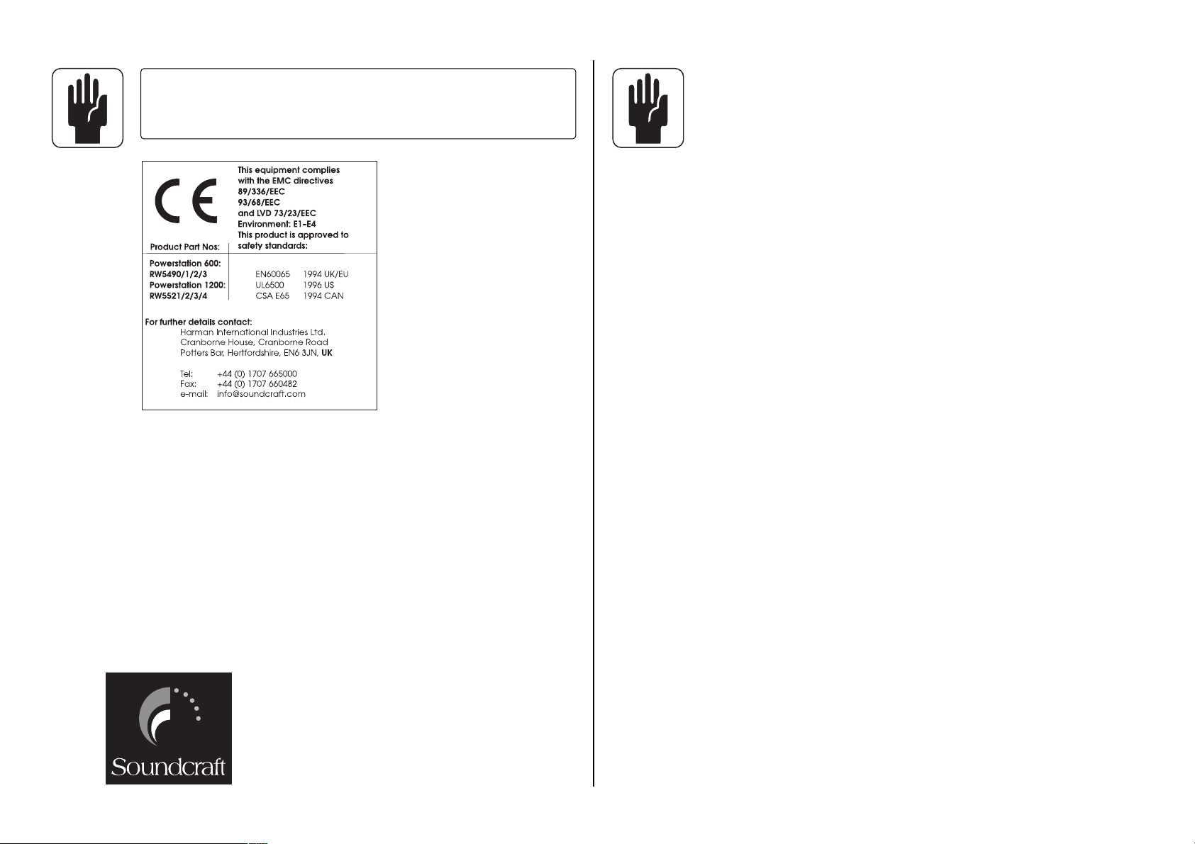
IMPORTANT
Please read this manual carefully before connecting your Mixer to the
mains for the first time.
© Harman International Industries Ltd. 2001
All rights reserved
Parts of the design of these products may be protected by worldwide patents.
Part No. ZM0210
Issue: 3
Soundcraft is a trading division of Harman International Industries Ltd. Information in this manual is
subject to change without notice and does not represent a commitment on the part of the vendor.
Soundcraft shall not be liable for any loss or damage whatsoever arising from the use of information
or any error contained in this manual.
No part of this manual may be reproduced, stored in a retrieval system, or transmitted, in any form
or by any means, electronic, electrical, mechanical, optical, chemical, including photocopying and
recording, for any purpose without the express written permission of Soundcraft.
Harman International Industries Limited
Cranborne House
Cranborne Road
POTTERS BAR
Hertfordshire
EN6 3JN
UK
Tel:+44 (0)1707 665000
Fax:+44 (0)1707 660742
http://www.soundcraft.com
WARRANTY
1 Soundcraft is a trading division of Harman International Industries Ltd .
End User means the person who first puts the equipment into regular operation.
Dealer means the person other than Soundcraft (if any) from whom the End User purchased
the Equipment, provided such a person is authorised for this purpose by Soundcraft or its
accredited Distributor. Equipment means the equipment supplied with this manual.
2 If within the period of twelve months from the date of delivery of the Equipment to the End
User it shall prove defective by reason only of faulty materials and/or workmanship to such
an extent that the effectiveness and/or usability thereof is materially affected the Equipment
or the defective component should be returned to the Dealer or to Soundcraft and subject
to the following conditions the Dealer or Soundcraft will repair or replace the defective components. Any components replaced will become the property of Soundcraft.
3 Any Equipment or component returned will be at the risk of the End User whilst in transit
(both to and from the Dealer or Soundcraft) and postage must be prepaid.
4 This warranty shall only be valid if:
a) the Equipment has been properly installed in accordance with instructions contained
in Soundcrafts manual; and
b) the End User has notified Soundcraft or the Dealer within 14 days of the defect
appearing; and
c) no persons other than authorised representatives of Soundcraft or the Dealer have
effected any replacement of parts maintenance adjustments or repairs to the
Equipment; and
d) the End User has used the Equipment only for such purposes as Soundcraft
recommends, with only such operating supplies as meet Soundcrafts specifications and otherwise in all respects in accordance Soundcrafts recommendations.
5 Defects arising as a result of the following are not covered by this Warranty:
faulty or negligent handling, chemical or electro-chemical or electrical influences,
accidental damage, Acts of God, neglect, deficiency in electrical power, air-conditioning or humidity control.
6 The benefit of this Warranty may not be assigned by the End User.
7 End Users who are consumers should note their rights under this Warranty are in addition to
and do not affect any other rights to which they may be entitled against the seller of the
Equipment.
Page 6
Page v
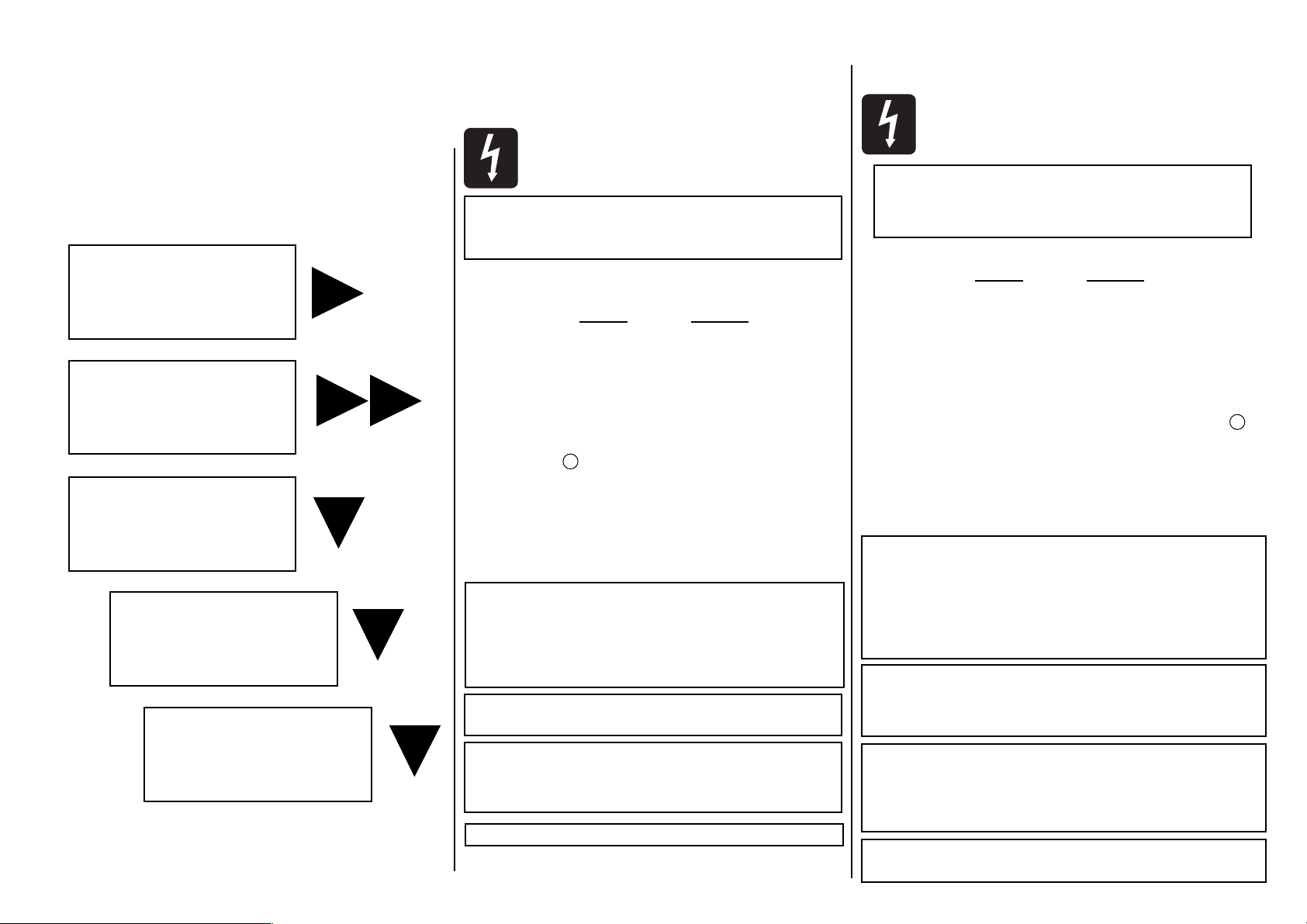
SAFETY PRECAUTIONS
WARNING: THIS UNIT MUST BE EARTHED
Under no circumstances should the mains earth be
disconnected from the mains lead.
The wires in the mains lead are coloured in accordance with the following
code:
UK & EU US & CAN
Earth / Ground: Green and Yellow Green and Yellow
Neutral: Blue White
Live: Brown Black
As the colours of the wires in the mains lead may not correspond with the
coloured markings identifying the terminals in your plug, proceed as follows:
l The wire which is coloured Green and Yellow must be connected to
the terminal in the plug which is marked with the letter E or by the
earth symbol.
l The wire which is coloured Blue or White must be connected to the
terminal in the plug which is marked with the letter N.
l The wire which is coloured Brown or Black must be connected to the
terminal in the plug which is marked with the letter L.
Ensure that these colour codings are followed carefully in the event of the
plug being changed.
This unit is capable of operating over a range of mains voltages by means of a 4-position mains input fuse carrier. It is
important to ensure that the correct voltage setting is
selected for the level of local mains voltage supply, for safe,
uninterrupted operation. Use a small screwdriver to prise
the fuse carrier from its location in the connector.
To avoid the risk of fire, replace the mains fuse only with
the correct value fuse, as marked on the rear panel.
The internal power supply unit contains no user
serviceable parts. Refer all servicing to a qualified
service engineer, through the appropriate
Soundcraft dealer.
Do not obstruct air vents.
INTRODUCTION
Thank you for purchasing a Powerstation mixer, brought to you with pride by the SPIRIT team - we hope you will have as
much fun using it as we did building it!
For your own safety and to
avoid invalidation of the
warranty please
read this section carefully.
Zu Ihrer eigenen Sicherheit und
damit die Garantie-Ansprüche
gewahrt bleiben,
lesen Sie bitte diesen Abschnitt
sehr sorgfältig durch!
Pour votre sécurité et pour
éviter dannuler la
garantie, lisez attentive-
ment cette section.
Per la vostra sicurezza e per
non invalidare la garanzia
leggette con la massima
attenzione i paragrafi
seguenti.
Para su propia seguridad y
para evitar la invalidación de
la garantía, por favor, lea
cuidadosamente esta
sección.
EINFÜHRUNG
Wir hoffen, daß Sie genauso viel Spaß mit Ihrem
Powerstation-Mixer haben, wie wir vom SPIRIT team.
SICHERHEITSHINWEISE
WARNUNG: DIE POWERSTATION Uß GEERDET SEIN.
Unter keinen Umständen darf das Erde-Kabel des
Netzsteckers von der Hauptstom-Versorgung getrennt
werden!
Die Adern der Netzkabel sind nach folgendem System farblich gekennz ichnet:
UK & EU US & CAN
Erde/Masse: Grün und Gelb Grün und Gelb
Negative Phase: Blau Weiß
Positive Phase: Braun Schwarz
Wenn es den Anschein hat, daß die farbliche Kennzeichnung der Adern Ihres
Netzkabels nicht mit den Anschlüssen der Netzbuchse übereinstimmt, gehen Sie
folgendermaßen vor:
l Die grün-gelbe Ader wird mit der Netzklemme verbunden, die mit dem
Großbuchstaben E bzw. dem Symbol für Masse gekennzeichnet ist.
l Die blaue (oder weiße) Ader wird mit der Netzklemme verbunden, die mit
dem Großbuchstaben N gekennzeichnet ist.
l Die braune (oder schwarze) Ader wird mit der Netzklemme verbunden,
die mit dem Großbuchstaben L gekennzeichnet ist.
Überprüfen Sie dieses Farbschema erneut, falls das Netzkabel, der Netzstecker
oder die Netzbuchse ausgetauscht wird.
Das Mischpult kann mit 4 unterschiedlichen Netzspannungen
betrieben werden. Es ist daher sehr wichtig, daß die eingestellte
Netzspannung mit der an der Steckdose anliegenden
Netzspannung übereinstimmt. Eine falsch eingestellte
Netzspannung kann zu einem Defekt am Mischpult führen. Mit
einem kleinen Schraubenzieher wird der Sicherungsträger in
richtige Netzposition gebracht.
Um die Gefahr eines Elektrobrandes zu verhindern, dür-
fen nur Hauptsicherungen am Netzgerät ersetzt wer-
den, wie sie entsprechend auf dem Gerätegehäuse
aufgeführt sind.
Das eingebaute Netzgerät enthält keine Komponenten,
die vom Benutzer gewechselt werden könnten.
Eventuelle Serviceleistungen nur qualifiziertem
Fachpersonal oder dem Soundcraft-Fachmann
überlassen.
Halten Sie immer die Luftschlitze der
Powerstation frei!.
W
W
Page 7

Page vi
INTRODUCTION
Nous vous remercions davoir acheté une console Powerstation.
Elle a été conçue pour vous, avec fierté, par léquipe SPIRIT. Nous
espérons quelle vous apportera autant de plaisir quà nous.
PRECAUTIONS
ATTENTION: CETTE APPAREIL DOIT IMPERATIVE-
MENT ETRE RELIE A LA TERRE.
En aucune circonstance, la terre ne doit être décon-
nectée du câble secteur.
Les conducteurs du câble secteur sont identifiés comme suit :
UK & EU US & CAN
Terre: Vert et Jaune Vert et Jaune
Neutre
: Bleu Blanc
Phase: Brun Noir
La couleur des câbles secteur peut ne pas correspondre avec les couleurs
par lesquelles se distinguent les connecteurs de la prise secteur. Dans ce
cas, procédez comme suit :
l Le conducteur vert et jaune doit être connecté au plot marqué de la
lettre E ou du symbole de Terre.
l Le conducteur bleu (ou blanc) doit être connecté au plot marqué de
la lettre N.
l Le conducteur marron (ou noir) doit être connecté au plot marqué de
la lettre L.
Assurez-vous du respect scrupuleux de ces conventions si la prise vient à
être changée.
Cet appareil peut fonctionner avec des tensions différentes à
l'aide d'un porte-fusible 4 positions. Il est important de vérifier
que le fusible installé offre les caractéristiques appropriées avant
de mettre l'appareil sous tension. Utilisez un petit tournevis pour
dégager le fusible si nécessaire.
Pour éviter tout risque dincendie, remplacez le fusible
uniquement par un fusible de la valeur correcte
indiquée sur lalimentation.
Lalimentation interne ne contient pas de pièces acces-
sibles par lutilisateur.Référez-vous à
du personnel qualifié.
Ne pas gêner la ventilation
INTRODUZIONE
Vi ringraziamo per lacquisto del mixer POWERSTATION, orgoglio
del gruppo di lavoro SPIRIT.
SICUREZZA
Per la vostra sicurezza e per non invalidare la garanzia
leggere attentamente questa sezione
QUESTO APPARECCHIO DEVE ESSERE
COLLEGATO A TERRA
In nessun caso la massa deve essere staccata dal cavo di alimentazione.
I conduttori del cavo di alimentazione devono essere colorati secondo il seguente codice:
UK & EU US & CAN
Massa: Verde e Giallo Verde e Giallo
Neutro: Blu Bianco
Contatto: Marrone Nero
Poichè i colori dei terminali nella vostra presa potrebbero non essere corrispondenti a questi, si consiglia di procedere come segue:
l Il cavo Verde e Giallo deve essere collegato al terminale indicato con
la lettera E e/o con il simbolo di massa.
l Il cavo Blu (o Bianco) deve essere collegato al terminale indicato con la
lettera N.
l Il cavo Marrone (o Nero) deve essere collegato al terminale indicato
con la lettera L.
Assicurarsi che queste indicazioni siano rispettate in caso di sostituzione
della presa.
Questo apparecchio può funzionare con diverse tensioni grazie ad
un porta-fusibili a 4 posizioni. Assicurarsi di selezionare la tensione
adatta alla rete per un funzionamento sicuro e duraturo. La
selezione avviene ruotando il porta-fusibile con un cacciaviti.
Per evitare il rischio di incendi, sostituire il fusibile solo
con un altro di pari valore, come indicato sul
pannello posteriore
Lalimentatore interno non contiene parti che possono
essere riparate dallutente. Rivolgersi quindi ad un
centro di assistenza autorizzato
Non ostruire le griglie di ventilazione
INTRODUCCIÓN
Gracias por adquirir un mezclador Powerstation, creado con orgullo para usted por el equipo SPIRIT.
PRECAUCIONES DE SEGURIDAD
ATENCIÓN: ESTA UNIDAD DEBE ESTAR
CONECTADA A TIERRA
Bajo ninguna circunstancia la toma de tierra debe ser
desconectada del cable de alimentación principal
Los conductores en el terminal de red se encuentran codificados por colores del siguiente modo:
UK & EU US & CAN
Tierra: Verde y Amarillo Verde y Amarillo
Neutro: Azul Blanco
Vivo: Marrón Negro
En caso de que los colores de los conductores del terminal de red no coincidan con los colores de las marcas que identifican los terminales en su
enchufe, proceda del siguiente modo:
l El conductor de color verde y amarillo debe conectarse al terminal del
enchufe que este marcado con la letra E o por el símbolo de tierra.
l El conductor de color azul (o blanco) debe conectarse al terminal del
enchufe que este marcado con la letra N, o sea, de color negro.
l El conductor de color marrón (o negro) debe conectarse al terminal
del enchufe que este marcado con la letra L, o sea, de color rojo.
Asegúrese de seguir cuidadosamente este código de colores en caso de
que deba sustituirse el enchufe
Esta unidad es capaz de trabajar sobre una gama de tensiones de
red gracias al soporte del fusible de 4 posiciones. Para un funcionamiento seguro y continuado es importante asegurar que se
selecciona la tensión correcta al nivel de la tensión de red local.
Use un pequeño destornillador para levantar el soporte del fusible
de su posición en el conector.
Para evitar riesgos de incendio, sustituya el fusible sólo
con otro del mismo valor, como se indica
en el panel trasero
La fuente de alimentación interna contiene partes no
reemplazables por el usuario. Para reparaciones dirí-
jase a un servicio técnico oficial, a través de
su distribuidor Spirit.
No obstruya las ventilaciones.
W
W
W
Page 8
Page vii
CAUTIONS
Do not install near any heat sources such as radiators, heat resis-
tors, stoves, or other apparatus (including amplifiers) that produce
heat.
Do not use this apparatus near water.
Do not defeat the safety purpose of the polarized or grounding
type plug.
A polarized plug has two blades with one wider than the other. A
grounding type plug has two blades and a third grounding prong.
The wide blade or the third prong are provided for your safety.
When the provided plug does not fit into your outlet, consult an
electrician for replacement of the obsolete outlet.
Protect the power cord from being walked on or pinched partic-
ularly at plugs, convenience receptacles and the point where they
exit from the apparatus.
Only use cables and hardware specified by the manufacturer.
Unplug this apparatus during lightning storms or when unused for
long periods of time.
Refer all servicing to qualified service personnel. Servicing is
required when the apparatus has been damaged in any way such
as power-supply cord or plug is damaged., liquid has been spilled
or objects have fallen into the apparatus, the apparatus has been
exposed to rain or moisture, does not operate normally or has
been dropped.
It is recommended that all maintenance and service on the prod-
uct should be carried out by Soundcraft or its authorised agents.
Soundcraft cannot accept any liability whatsoever for any loss or
damage caused by service, maintenance or repair by unauthorised
personnel.
If a trolley is used, use caution when moving the trolley / appara-
tus combination to avoid injury from tip-over.
WARNINGS
Read these instructions.
Keep these instructions.
Heed all warnings.
Follow all instructions.
This unit contains no user serviceable parts. Refer all servicing to
a qualified service engineer, through the appropriate Soundcraft
dealer.
Clean only with a damp cloth.
DO NOT block any of the ventilation openings. DO NOT install
where air cannot flow over the rear of the unit.
DO Install in accordance with the manufacturers instructions.
Page 9

Page viii
WARNUNGEN
Betreiben Sie das Gerät nicht in direkter Nähe von Wärmequellen
wie Radiatoren, Wärmespeichern, Heizkörpern oder anderen
Vorrichtungen (inklusive Leistungsverstärkern), die Wärme produzieren
Schützen Sie das Gerät vor Feuchtigkeit und betreiben Sie es nicht
in der Nähe von fließendem Wasser.
Verändern bzw. modifizieren Sie in keinem Fall den Schutzleiter
eines geerdeten Netzsteckers.
Ein Schukostecker mit Erdung verfügt über zwei Anschlußstifte
sowie einen dritten Massekontakt. Massekontakt des
Schukosteckers sorgt dafür, daß Sie vor Stromschlägen oder einem
Kurzschluß geschützt sind. Wenn der im Lieferumfang befindliche
Stecker nicht zu Ihrem Netzanschluß paßt, wenden Sie sich an ein
qualifizierten Elektriker.
Verlegen Sie das Netzkabel so, daß es keinen äußeren Belastungen
ausgesetzt ist. Achten Sie besonders darauf, daß die Stecker nicht
gequetscht werden oder an den Netz- bzw. Gerätebuchsen unter
Zug stehen.
Verwenden Sie ausschließlich vom Hersteller empfohlene Kabel und
Hardware.
Entfernen Sie das Gerät vom Netz im Falle eines Gewitters oder
wenn Sie es für längere Zeit nicht benutzen werden.
Wenden Sie sich im Servicefall ausschließlich an qualifiziertes
Fachpersonal. Der Servicefall tritt ein, wenn das Gerät in irgendeiner Form beschädigt ist, z.B. wenn:
- das Netzkabel oder die Netzbuchse beschädigt ist
- Flüssigkeiten oder Gegenstände in das Geräteinnere gelangt sind
- das Gerät Regen oder Feuchtigkeit ausgesetzt war
- das Gerät nicht einwandfrei funktioniert oder heruntergefallen ist.
Es wird empfohlen, alle Wartungsarbeiten und Reparaturen direkt
von Soundcraft oder einem autorisierten Vertreter ausführen zu
lassen. Soundcraft kann keine Verantwortung für Verluste oder
Schäden in jeglicher Form übernehmen, die aufgrund von
Serviceleistungen, Wartungsarbeiten oder Reparaturen durch
unqualifiziertes Personal auftreten.
Sofern Sie das Gerät auf einem Rollwagen betreiben bzw. bewegen,
geben Sie besonders darauf Acht, daß der Wagen aufgrund des
hohen Schwerpunktes nicht kippt.
HINWEISE
Lesen Sie diese Anleitung sorgfältig durch.
Bewahren Sie diese Anleitung auf.
Leisten Sie allen Hinweisen in jedem Fall Folge.
Leisten Sie allen Informationen in dieser Anleitung unbedingt Folge.
Dieses Gerät enthält keine Bauteile, die vom Anwender ausge-
tauscht werden können. Wenden Sie sich im Reparaturfall an Ihren
Soundcraft-Händler bzw. an qualifiziertes Fachpersonal.
Reinigen Sie das Gerät nur mit einem trockenen Tuch.
ACHTEN Sie darauf, daß die Lüfteröffnungen nicht verstellt wer-
den, so daß eine ausreichende Belüftung gewährleistet ist. ACHTEN
SIE bei der Installation des Gerätes darauf, daß auch die
Geräterückseite mit Frischluft versorgt wird.
FÜHREN SIE die Installation gemäß den Anleitungen des Herstellers
durch.
Page 10
Page ix
PRECAUTIONS
N'installez pas l'appareil à proximité de sources de chaleur telles
que radiateurs, résistances chauffantes, réchauds ou autres
appareils susceptibles de produire de la chaleur (y compris les
amplificateurs) .
N'utilisez pas cet appareil près d'un point d'eau.
N'endommagez pas le dispositif de mise à la terre de la prise
secteur. Une prise avec mise à la terre présente trois plots. La
terre est garante de votre sécurité. Si la prise de l'appareil ne
s'adapte pas parfaitement à votre prise secteur murale, adressezvous à un électricien.
Veillez à ce que le cordon d'alimentation ne soit ni écrasé ni pincé,
en particulier au niveau de l'appareil et de la prise secteur murale.
Veillez à n'utiliser que les câbles, connecteurs et accessoires
recommandés par le fabricant.
Débranchez l'appareil en cas d'orage ou d'inutilisation prolongée.
Adressez-vous à un technicien qualifié pour toute réparation.
L'appareil doit être confié à un technicien qualifié dans les cas suivants : lorsque le cordon d'alimentation ou l'embase secteur ont été
endommagés, qu'un liquide ou un objet s'est introduit dans l'appareil, que l'appareil a été exposé à la pluie ou à l'humidité, que
l'appareil montre des signes de dysfonctionnement ou qu'il soit
tombé.
La maintenance et les réparations doivent être assurées par un
revendeur agréé par Soundcraft ou son distributeur. La garantie ne
pourra pas s'appliquer en cas de dommage causé par un réparateur non agréé.
Si un chariot élévateur est utilisé pour déplacer l'appareil, maniez
l'ensemble avec précaution pour éviter la chute de l'appareil et les
risques de blessures.
AVERTISSEMENTS
Lisez attentivement ces instructions.
Conservez ces instructions
Tenez compte de ces instructions.
Suivez toutes les instructions.
Aucun élément de cet appareil n'est réparable par l'utilisateur.
Adressez-vous à un technicien qualifié pour toute réparation par
l'intermédiaire du distributeur Soundcraft.
Nettoyez l'appareil avec un chiffon sec.
N'obstruez pas les ouïes de ventilation. L'installation doit permet-
tre la circulation de l'air à l'arrière de l'appareil.
L'installation doit être conforme aux instructions des fabricants.
Page 11
Page x
AVVERTENZE
Non installare vicino a fonti di calore come radiatori, caloriferi,
stufe o altre apparecchiature che producono calore (amplificatori
inclusi).
Non utilizzare queste apparecchiature vicino all'acqua.
Non manomettere in alcun modo il cavo di alimentazione.
Proteggere il cavo da evenutali calpestii ed evitare di strappare il
cavo dalla presa.
Usare solo cavi indicati dal fabbricante.
Scollegare l'alimentazione durante i temporali o quando l'apparec-
chio non viene utilizzato per lunghi periodi di tempo.
Per l'assistenza rivolgersi solo a personale qualificato. L'assistenza
deve essere richiesta quando gli apparecchi subiscono danni per
motivi diversi, ad es. il cavo o la presa di alimentazione sono stati
danneggiati, liquidi o altri oggetti sono caduti sulle apparecchiature, le apparecchiature sono state esposte a pioggia o umidita,
non funzionano normalmente o sono cadute.
Si raccomanda che la manutenzione ed il servizio assistenza sul
prodotto siano eseguiti da Soundcraft o dai suoi distributori autorizzati. Soundcraft non accetta nessuna responsabilita per alcuna
perdita o danno causati da assistenza e riparazioni eseguiti da personale non autorizzato.
Se trasportato su carrello, fare attenzione quando viene spostato
per evitare lesioni da accidentale capovolgimento.
ATTENZIONE
Leggere queste istruzioni.
Conservare queste istruzioni.
Fare attenzione a tutte le avvertenze.
Seguire tutte le istruzioni.
Questa unita non contiene parti di ricambio. Fare riferimento ai
centri di assistenza qualificati attraverso il rivenditore Soundcraft
autorizzato.
Pulire solo con un panno morbido ed asciutto.
NON chiudere nessuna delle aperture di ventilazione. NON
installare dove non c'e abbastanza flusso d'aria intorno alle
apparecchiature.
Installare seguendo le indicazioni fornite dal costruttore.
Page 12

Page xi
PRECAUCIONES
No instalar cerca de fuentes de calor, tales como radiadores,
resistencias de calor, estufas u otro aparato emisor de calor
(incluyendo amplificadores).
No usar este aparato cerca del agua.
No eliminar las especificaciones de seguridad marcadas por la
polaridad o la toma de tierra del conector de alimentación. Un
conector polarizado tiene dos patillas con una mayor que la otra.
Un conector con toma de tierra tiene dos patillas y una tercera
para conexión de tierra. Esta tercera patilla más ancha suministra
seguridad eléctrica al equipo. Si el conector suministrado no encaja en su toma de corriente, consulte a un electricista para instalar
una toma correcta.
Proteger el cable de alimentación para que no sea pisado o pelliz-
cado, especialmente en los conectores y en el punto de la salida
del aparato.
Utilizar solamente cables y accesorios especificados por el fabri-
cante.
Desconectar este aparato durante tormentas eléctricas o cuando
no se vaya a utilizar por un largo período de tiempo.
Cualquier reparación tiene que efectuarse por personal cualifica-
do. Llame al servicio técnico cuando el aparato haya sufrido
cualquier daño, si el cable o conector de alimentación han sido
dañados; si se ha vertido liquido u objetos han caído en el aparato; si el aparato ha sido expuesto a la lluvia o humedad; si no funciona correctamente o se ha caído al suelo.
Se recomienda que el mantenimiento y cualquier reparación del
producto sea efectuado por Soundcraft o sus distribuidores autorizados. Soundcraft no aceptará ninguna reclamación por pérdidas
o daños causados en mantenimiento, reparaciones u otro servicio
efectuado por personas no autorizadas.
Si el aparato está colocado en una caretilla, tome las precauciones
necesarias para evitar que esta pueda volcar.
ADVERTENCIAS
Lea estas instrucciones atentamente.
Guarde estas instrucciones para futuras consultas.
Haga caso de todas las advertencias.
Siga todas las instrucciones
Esta unidad no contiene partes reparables por el usuario. Llame al
servicio técnico del representante de Soundcraft en su zona.
Limpiar solo con un paño húmedo.
No bloquear ni tapar ninguna de la aperturas de ventilación. No
instalar en un lugar donde no pueda circular el aire por la parte
posterior del producto.
Instalar de acuerdo con las instrucciones del fabricante.
Page 13

Page xii
Page 14

Contents
Connecting Up . . . . . . . . . . . . . . . . . . . 1
Anschlüsse . . . . . . . . . . . . . . . . . . . . . . . . . . . . . . . 1
Raccordement . . . . . . . . . . . . . . . . . . . . . . . . . . . . . 1
Collegamento . . . . . . . . . . . . . . . . . . . . . . . . . . . . . 1
Conexiones . . . . . . . . . . . . . . . . . . . . . . . . . . . . . . . 1
Using the Powerstation . . . . . . . . . . . . 2
Anwendung . . . . . . . . . . . . . . . . . . . . . . . . . . . . . . . 2
Utilisation de la Powerstation . . . . . . . . . . . . . . . . . . 3
Utilizzo del Mixer Powerstation . . . . . . . . . . . . . . . . 3
Usando la Powerstation . . . . . . . . . . . . . . . . . . . . . . 3
Setting Up & Troubleshooting . . . . . . . 22
Erste Einstellungen am Mischpult . . . . . . . . . . . . . . . 23
Réglages st problèmes de foncionnement . . . . . . . . . . 23
Set Up & Individuzione dei guasti . . . . . . . . . . . . . . . 23
Ajuste y Solución de Problemas . . . . . . . . . . . . . . . . . 23
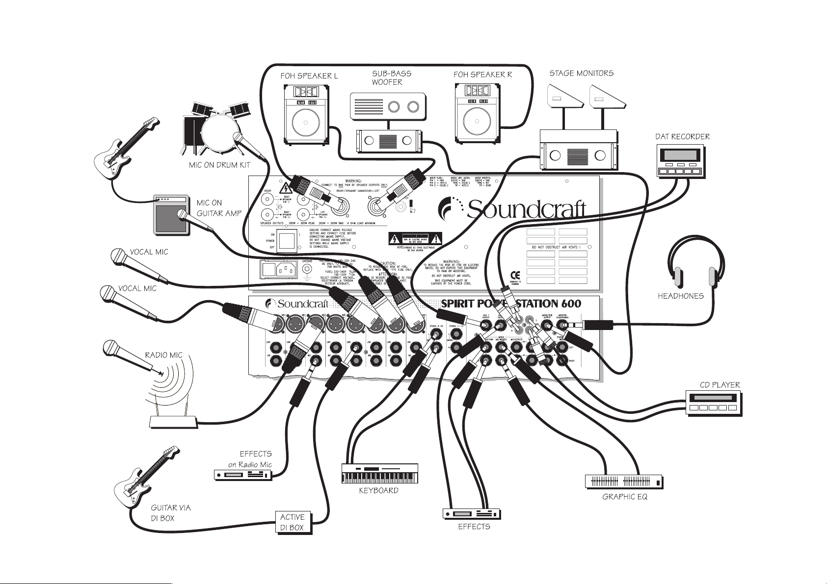
Applications . . . . . . . . . . . . . . . . . . . . .25
Anwendungen . . . . . . . . . . . . . . . . . . . . . . . . . . . . . 25
Applications . . . . . . . . . . . . . . . . . . . . . . . . . . . . . . 25
Applicazioni . . . . . . . . . . . . . . . . . . . . . . . . . . . . . . . 25
Aplicaciones . . . . . . . . . . . . . . . . . . . . . . . . . . . . . . 25
System Block Diagram . . . . . . . . . . . .31
Block Diagramm . . . . . . . . . . . . . . . . . . . . . . . . . . . 31
Synoptique . . . . . . . . . . . . . . . . . . . . . . . . . . . . . . . 31
Diagramma a blocchi) . . . . . . . . . . . . . . . . . . . . . . . 31
Diagrama de Bloques del Sistema . . . . . . . . . . . . . . . 31
Connecting Leads . . . . . . . . . . . . . . . .32
Ideale kabel und kabel-verbindungen . . . . . . . . . . . . .32
Connexions . . . . . . . . . . . . . . . . . . . . . . . . . . . . . . . .32
Collegamenti . . . . . . . . . . . . . . . . . . . . . . . . . . . . . . .32
Conectando los cables . . . . . . . . . . . . . . . . . . . . . . . .32
Technical Information . . . . . . . . . . . . . 33
Technische Informationen . . . . . . . . . . . . . . . . . . . . . 33
Informations Techniques . . . . . . . . . . . . . . . . . . . . . . 33
Informazioni Tecniche . . . . . . . . . . . . . . . . . . . . . . . 33
Información Técnica . . . . . . . . . . . . . . . . . . . . . . . . . 33
Page 15
Page 1
Connecting Up
Anschlüsse
Raccordement
Collegamento
Conexiones
Page 16

Page 2
Using the POWERSTATION
MONO INPUT CHANNEL
MICROPHONE INPUT
The mic input accepts XLR-type connectors and is designed to suit a wide
range of BALANCED or UNBALANCED signals. Professional dynamic,
condenser or ribbon mics are best because these will be LOW IMPEDANCE. You can use low-cost HIGH IMPEDANCE mics, but the level of
background noise will be higher. If you press the MIC +48V switch down
(on the Master section) the socket provides a suitable powering voltage for
professional condenser mics (this is also known as Phantom Power).
ONLY connect condenser microphones with the +48V
powering OFF (switch UP), and ONLY turn the +48V
powering on or off with all output faders DOWN, to
prevent damage to the mixer or external devices.
TAKE CARE when using unbalanced sources, which
may be damaged by the phantom power voltage on
pins 2 & 3 of the XLR connector.
Unplug any mics if you want to use the LINE Input. The input level is set
using the GAIN knob.
LINE INPUT
Accepts 3-pole `A gauge (TRS) jacks. Use this high impedance input for
sources other than mics, such as keyboards, drum machines, synths, tape
machines or guitars. The input is BALANCED for low noise and top quality from professional equipment, but you can use UNBALANCED sources
by wiring up the jacks as shown, although you should then keep cable
lengths as short as possible. Unplug anything in the MIC input if you want
to use this socket. Set the input level using the GAIN knob.
INSERT
The unbalanced, pre-EQ insert point is a break in the channel signal path,
allowing limiters, compressors, special EQ or other signal processing units
to be added in the signal path. The Insert is a 3-pole A gauge jack socket
which is normally bypassed. When a jack is inserted, the signal path is broken just after the High-Pass Filter and before the EQ section. The Send may
be tapped off as an alternative pre-fade, pre-EQ direct output if required,
using a lead with tip and ring shorted together so that the signal path is not
interrupted.
Einsatz der Powerstation
MONO EINGANGSKANAL
MIKROFONEINGANG
Der Mikrofoneingang ist mit XLR-Buchsen ausgestattet und kann eine
Vielzahl symmetrischer als auch unsymmetrischer Signale verarbeiten.
Professionelle dynamische, Kondensator- oder Bändchen-Mikrofone sind
am besten geeignet, da diese bei niedriger Impedanz arbeiten. Sie können
auch günstige Mikrofone mit hoher Impedanz verwenden, bei denen
allerdings die Hintergrundgeräusche höher sein werden. Wenn Sie den
MIC +48V Schalter in der Mastersektion drücken, so liefert die XLRBuchse eine Spannung für Kondensatormikrofone (auch als
Phantomspeisung bekannt).
Verwenden Sie ausschließlich Kondensatormikrofone
mit +48V und schalten die +48V Speisung nur an/aus,
wenn alle Fader heruntergezogen sind! Sie vermeiden
damit Beschädigungen am Mixer sowie an externen
Geräten.Seien Sie bei der Verwendung unsym-
metrischer Quellen vorsichtig, da die
Phantomspeisung über die Pins 2 und 3 des XLR-
Steckers geleitet wird.
Verwenden Sie den LINE-Eingang, dann ziehen Sie das Mikrofon heraus.
Der Eingangspegel wird mit dem Gain-Drehregler justiert.
LINE-EINGANG
Nimmt 3-polige Klinken-Stecker auf. Verwenden Sie diesen Eingang für
Signalquellen wie Keyboards, Drumcomputer, Bandmaschinen oder
Gitarren. Der Eingang ist für geräuscharme, hochwertige Arbeitsweise
symmetrisch ausgelegt. Wenn Sie unsymmetrisches Equipment verwenden, dann sollten Sie auf die gezeigte Steckerbelegung achten. Vermeiden
Sie außerdem zu lange Kabel. Entfernen Sie jegliche Stecker aus dem MICEingang, wenn Sie diese Buchse verwenden. Die Pegeleinstellung geschieht
über den Gain-Regler.
INSERT
Der unsymmetrische Einschleifpunkt (pre-EQ) unterbricht den Signalfluß
im Kanal, um Limiter, Kompressoren, spezielle EQs und ähnliche
Signalprozessoren in den Kanal einschleifen zu können. Der Insert ist ohne
Funktion, wenn kein Stecker in der Buchse ist. Ist hingegen ein Stecker
eingesteckt, so wird das Signal nach dem Hochpaßfilter und vor dem EQ
unterbrochen. Die Send-Leitung kann als pre-Fader, pre-EQ Direct Output
verwendet werden, wenn Tip und Ring miteinander verbunden werden,
damit der Signalfluß nicht unterbrochen wird.
Page 17

Page 3
UTILISATION DE LA POWERSTATION
VOIE DENTRÉE MONO
Entrée Micro
Lentrée micro sur connecteur de type XLR est conçue pour convenir à une
large gamme de signaux SYMETRIQUES ou ASYMETRIQUES. Les micros
professionnels dynamiques, statiques ou à ruban sont les meilleurs parce
quils sont à BASSE IMPEDANCE. Vous pouvez utiliser des micros peu
coûteux à HAUTE IMPEDANCE, mais le niveau du bruit de fond sera plus
haut. Si vous mettez lalimentation FANTOME en service à laide de la
touche située à côté de la prise casque, lembase fournit la tension appropriée pour des micros professionnels statiques.
Débranchez le micro si vous voulez utiliser lentrée
LIGNE. Le gain dentrée est réglé par le
potentiomètre GAIN.
ENTREE LIGNE
Cette entrée sur jack 6.35 STEREO est destinée à des sources autres que
des micros, telles que des claviers, des botes à rythmes, des synthétiseurs,
des magnétophones ou des guitares. Lentrée est SYMETRIQUE pour un
bon rapport signal/bruit et pour du matériel professionnel, mais vous pouvez utiliser des sources ASYMETRIQUES en câblant les jacks comme montré ; dans ce cas utilisez des câbles aussi courts que possible. Débranchez
tout micro de lentrée MICRO si vous voulez utiliser cette embase. Le gain
dentrée est réglé par le potentiomètre GAIN.
INSERT
Le point dinsertion asymétrique, pré-correcteur est une rupture dans le
circuit de voie, permettant dinsérer des limiteurs, des compresseurs, un
correcteur spécial ou dautres appareils de traitement de signaux.
Linsertion utilise une embase jack 6.35 stéréo qui est normalement bypassée. Quand une prise est insérée, le circuit est coupé, juste avant la
section CORRECTEUR. Le départ insert peut être utilisé en tant que sortie directe avant fader et avant correcteur, en créant une liaison entre lextrémité et lanneau du jack de sorte que le circuit ne soit pas interrompu.
USO DEL MIXER
Ingresso Mic
Lingresso mic accetta connettori XLR e una vasta gamma di segnali BILANCIATI E NON BILANCIATI. I microfoni professionali dinamici, a condensatore o a nastro sono consigliati essendo A BASSA IMPEDENZA. E possibile usare microfoni economici ad ALTA IMPEDENZA, ma in questo caso il
livello del rumore di fondo sarà maggiore. Premendo il tasto MIC 48V (nella
Sezione Master) la presa viene alimentata in modo adeguato per i microfoni
professionali a condensatore (Alimentazione Phantom).
Il collegamento di microfoni a condensatore deve avvenire SOLO con
lAlimentazione Phantom 48V disattivata (tasto rilasciato).
Essa va inoltre attivata/disattivata SOLO quando i cur-
sori delle uscite sono abbassati, per evitare danni al
mixer o alle apparecchiature esterne
eventualmente collegate.
FARE ATTENZIONE in caso di sorgenti non bilanciate
che potrebbero risultare danneggiate dallalimen-
tazione Phantom sui terminali 2 & 3 del
connettore XLR.
Per usare lingresso LINE bisogna staccare tutti i microfoni. Il livello viene
regolato dalla manopola GAIN
INGRESSO LINE
Presa jack a 3 poli `A gauge (TRS). Questo è un ingresso ad alta impedenza per sorgenti che non siano microfoni (tastiere, drum machine, sintetizzatori, registratori o chitarre).Lingresso è BILANCIATO in modo da ottenere
la massima qualità ed il minimo rumore con gli apparecchi professionali.
Tuttavia è possibile usare sorgenti NON BILANCIATE collegando i jack
come indicato nel diagramma e mantenendo la lunghezza dei cavi al minimo.
Per usare questa presa bisogna staccare ogni collegamento nellingresso
MIC. Il livello viene regolato dalla manopola GAIN.
INSERT
Linsert point non bilanciato, pre-EQ è uninterruzione nel percorso del segnale che permette laggiunta di limiter, compressori, EQ speciali o altri dispositivi di trattamento. LInsert è una presa jack a 3 poli A normalmente
bypassata. Quando viene inserito un jack, il percorso del segnale viene interrotto dopo il filtro passa-alto e prima della sezione EQ. Se necessario, la
Mandata può anche essere usata come uscita diretta alternativa pre-fade,
pre-EQ, con un cavo in cui punta e anello siano messi in corto circuito per
non interrompere il segnale.
Usando la POWERSTATION
CANAL DE ENTRADA MONO
ENTRADA DE MICROFONO
La entrada de micrófono acepta conectores de tipo XLR y está diseñada
para adaptarse a una amplia gama de señales balanceadas o no balanceadas.
Los micrófonos dinámicos, de condensador o de cinta profesionales son
mejores porque presentan baja impedancia. Puede usar micrófonos
económicos de alta impedancia, pero el nivel del ruido de fondo será mayor.
Si pulsa el botón MIC +48V (en la sección master) el conector ofrece una
tensión adecuada para los micrófonos de condensador (se conoce como alimentación phantom).
SÓLO conecte micrófonos de condensador con la ali-
mentación de +48V desactivada (botón arriba), y
SÓLO active y desactive la alimentación +48V con
todos los faders bajados para prevenir daños al mez-
clador o a equipos externos.
TENGA CUIDADO al usar fuentes no balanceadas, ya
que pueden resultar dañadas por la tensión phantom
en los pines 2 y 3 del conector XLR.
Desconecte el micrófono si desea usar la entrada de lnea. El nivel de entrada se ajusta usando el potenciómetro GAIN.
ENTRADA DE LÍNEA
Acepta jacks de 3 polos de tipo A (TRS). Use esta entrada de alta impedancia para fuentes diferentes a micrófonos, como teclados, cajas de ritmos,
sintetizadores, equipos de cinta o guitarras. La entrada está balanceada para
obtener un bajo ruido y la máxima calidad con equipos profesionales, pero
puede usar fuentes no balanceadas cableando los jacks como se muestra,
aunque entonces debe mantener las distancias de los cables tan cortas
como sea posible. Desconecte lo que haya en la entrada MIC si desea usar
esta entrada. Ajuste el nivel de entrada usando el control GAIN.
INSERCIÓN
El punto de inserción no balanceado, pre-EQ es una abertura en el camino
de la señal que permite añadir limitadores, compresores, ecualización especial u otras unidades de procesado de señal. La inserción es un conector
jack de tipo A de tres polos que normalmente está en bypass. Cuando se
inserta un jack, el recorrido de la señal se rompe tras el filtro pasa altos y
antes del ecualizador. Si lo desea, el envío puede extraerse como una salida
directa pre-fader, pre-EQ alternativa, usando un cable con el envío y el
retorno (tip y ring del jack) interconectados para no cortar el recorrido de
la señal.
Page 18

Page 4
GAIN CONTROL
This knob sets how much of the source signal is sent to the rest of the
mixer. Too high, and the signal will distort as it overloads the channel. Too
low, and the level of any background hiss will be more noticeable and you
may not be able to get enough signal level to the output of the mixer.
Setting the knob to the 10dB mark gives unity gain for the LINE input. Note
that some sound equipment, particularly that intended for domestic use,
operates at a lower level (-10dBV) than professional equipment and will
therefore need a higher gain setting to give the same output level.
See `Setting Up & Troubleshooting on page ?? to learn how to set GAIN
correctly.
100Hz HI-PASS FILTER
Pressing this switch activates a steep 18dB per octave filter which reduces
the level of bass frequencies only. Use this in live PA situations to clean up
the mix, reducing stage rumble or popping from microphones.
EQUALISER
The Equaliser (EQ) allows fine manipulation of the frequency bands, and is
particularly useful for improving the sound in live PA applications where the
original signal is often far from ideal and where slight boosting or cutting of
particular voice frequencies can really make a difference to clarity.
HF EQ
Turn clockwise to boost high (treble) frequencies (12kHz and above) by up
to 15dB, adding crispness to cymbals, vocals and electronic instruments.
Turn anticlockwise to cut by up to 15dB, reducing hiss or excessive sibilance
which can occur with certain types of microphone. Set the knob in the centre-detented position when not required.
MID EQ
This pair of knobs work together to form a MID frequency EQ section. The
lower knob provides 15dB of boost and cut, just like the HF EQ knob, but
the frequency at which this occurs can be set by the upper knob over a
range of 250Hz to 6kHz. This allows some truly creative improvement of
the signal in live situations, because the mid band covers the range of most
vocals. Listen carefully as you use these controls together to find how particular characteristics of, for instance, a vocal signal can be enhanced or
reduced. Set the gain (lower) knob to the centre-detented position when
not required. Note: Q is set at 1.5.
LF EQ
Turn clockwise to boost low (bass) frequencies (60Hz and below) by up to
15dB, adding warmth to vocals or extra punch to synths, guitars and drums.
Turn anticlockwise to cut low frequencies by up to 15dB for reducing hum,
stage rumble or to improve a mushy sound. Set the knob to the centredetented position when not required.
GAIN-REGLER
Dieser Regler bestimmt, welcher Pegelanteil in den Mixer geschickt wird.
Zu hoch eingestellt verzerrt das Signal im Kanalzug, während zu niedrig
gewählt die Nebengeräusche zunehmen und nicht genügend Pegel zum
Mix-Ausgang gelangt.Bei der 10 dB-Markierung erreichen Sie Unity-Gain
(Verstärkung = 1) für den Line-Eingang. Beachten Sie, daß insbesondere
Equipment aus dem Heimstudiobereich mit -10 dBV betrieben wird, und
deshalb eine entsprechend höhere Gain-Einstellung nötig ist.Lesen Sie auf
Seite 10 nach, um zu erfahren, wie man das Gain (Vorverstärkung) am
besten einstellt.100-H-HOCHPASSFILTERDieser Schalter aktiviert ein
Filter mit 18 dB Flankensteilheit, das Bassfrequenzen reduziert. Bei PAAnwendungen verbessern Sie den Mix und unterdrücken Trittschall auf der
Bühne sowie Mikrofonpoppen.
100 Hz-HOCHPASSFILTER
Durch Drücken des 100 Hz-Schalters wird ein Filter mit einer
Flankensteilheit von 18 dB/Oktave geschaltet. Dieses Filter reduziert nur
den Pegel der Bass-Frequenzen. In Live PA-Situationen werden zB.
Bühnenschwingungen oder Mikrofon-Poppen reduziert.
EQUALIZER
Der Equalizer (EQ) erlaubt die Feinabstimmung der Frequenzen und ist
besonders bei PA-Anwendungen nützlich, da gerade hier Signale oft nicht
originalgetreu klingen. Leichtes Anheben/Absenken der Frequenzen
verbessert hier das gesamte Klangbild.
HF EQ
Drehen Sie den Regler im Uhrzeigersinn, um die Höhen (12 kHz und
darüber) mit bis zu 15 dB anzuheben und Becken, Vocals oder elektronischen Instrumenten Schärfe zu verleihen. Drehen Sie ihn entgegen dem
Uhrzeigersinn, dann senken Sie diese Frequenzen ab und dämpfen
Störgeräusche oder andere unerwünschte Mikrofongeräusche. Wenn Sie
keine Veränderung vornehmen möchten, belassen Sie den Regler in der
Mittelstellung.
MID EQ
Diese beiden Regler sind für die mittleren Frequenzen (250 Hz bis 6 kHz)
zuständig. Davon senkt der untere (ebenso wie der HF-Reglerf) mit 15dB
ab bzw. hebt an, während der obere die einzelnen Frequenzen anwählt. Im
PA-Bereich ist das eine kreative Möglichkeit der Klangregelung, da die meisten Sprachsignale einen hohen Mittenanteil besitzen. Hören Sie aufmerksam zu, wie sich Stimmsignale dadurch bereichern lassen. In der
Mittelstellung findet keine Klangfärbung statt. Zur Beachtung: Der Q-Faktor
beträgt 1,5.
LF EQ
Arbeitet ebenfalls mit 15 dB Anhebung/Absenkung. Die Frequenzen liegen
bei 60 Hz und darunter. So verleihen Sie den Vocals mehr Wärme und einen
extra Punch (Druck) dem Schlagzeug, Synthesizer und den Gitarren.
Senken Sie die Frequenzen ab, um Trittschall zu unterdrücken oder einem
dumpfen Sound entgegenzuwirken. Wenn Sie keine Klangveränderung
brauchen, lassen Sie den Regler in der Mittelstellung.
Page 19

Page 5
GAIN (Sensibilité)
Ce potentiomètre permet dadapter la sensibilité du préampli micro au
niveau de signal de la source. Réglé trop haut, le signal sera distordu et surchargera la voie. Trop bas, le niveau de bruit sera plus audible et vous ne
pourrez pas obtenir assez de niveau en sortie de console.Le gain unitaire de
lentrée LIGNE est à la position 10dB. Notez que certains matériels audio,
en particulier ceux destinés à une utilisation domestique, fonctionnent à un
niveau plus bas (-10dBV) que le matériel professionnel et auront donc
besoin dun gain plus élevé pour donner le même niveau de sortie. Voir
Réglages et problèmes de fonctionnement à la page 10 pour apprendre
comment régler le potentiomètre GAIN correctement.
FILTRE PASSE-HAUT A 100Hz
Cette touche insère un filtre à 18dB par octave qui réduit le niveau des basses fréquences indésirables. A utiliser en sonorisation pour réduire les bruits
de scènes ou le «pop» des microphones.
CORRECTEUR
Le correcteur (EQ) permet une manipulation précise du son, daméliorer en
particulier le son en sonorisation où le signal initial est souvent loin dêtre
idéal et où une légère accentuation ou diminution des fréquences particulières de voix peut vraiment faire une différence de clarté. Il y a trois sections permettant dagir sur différentes plages de fréquence.
AIGUES
Tourné vers la droite, ce potentiomètre accentue de 15dB les fréquences
hautes (aigus) au-dessus de 12kHz, ajoutant de la brillance aux cymbales,
aux voix et aux instruments électroniques. Tourné vers la gauche il atténue
ces fréquences jusqu à 15dB, en réduisant le souffle excessif qui peut se
produire avec certains types de sources. La position neutre est repérée par
un déclic central.
MEDIUMS
Deux potentiomètres travaillent ensemble pour corriger les médiums. Le
potentiomètre inférieur accentue ou réduit de 15dB, comme le potentiomètre du correcteur daigus, mais la fréquence daction peut être réglée
par le potentiomètre supérieur sur une plage de 250Hz à 6kHz. Ceci permet une amélioration véritablement créatrice du signal en sonorisation,
cette bande médium couvrant la plage de la plupart des voix. Ecoutez
soigneusement lorsque vous utilisez ces commandes pour trouver comment les caractéristiques particulières dun signal vocal peuvent être
améliorées. La position neutre est repérée par un déclic central.
Note : Le coefficient Q est fixé à 1.5.
GRAVES
Tourné vers la droite, ce potentiomètre accentue de 15dB les basses
fréquences (graves) au-dessous de 60Hz, en ajoutant de la chaleur aux
vocaux ou du punch supplémentaire aux synthétiseurs, aux guitares et aux
batteries. Tourné vers la gauche, il coupe ces fréquences de 15dB pour
réduire le ronflement, ou pour éclaircir un son. La position neutre est
repérée par un déclic central.
GAIN
Questa manopola regola la quantità di segnale mandata al resto del mixer.
Se essa è troppo alta si avrà la distorsione dovuta al sovraccarico del canale.
Se è troppo bassa, il rumore di fondo (fruscio) sarà più evidente ed il livello
duscita dal mixer sarà inadeguato. La regolazione a 10dB offre il guadagno
unitario per lingresso LINE. Alcuni apparecchi, specialmente quelli per uso
domestico, funzionano a livelli più bassi (-10dBV) rispetto a quelli professionali perciò è necessario un guadagno maggiore per ottenere lo stesso livello duscita. Vedasi Set Up e guida ai guasti.
FILTRO PASSA-ALTO DA 100Hz
Questo tasto attiva un filtro passa-alto da 18dB per ottava che riduce il livello delle basse frequenze. Dal vivo questa funzione serve ad avere un
insieme sonoro più chiaro, riducendo il rumore del palco o il popping dei
microfoni.
EQUALIZZATORE
LEqualizzatore (EQ) permette di modificare con precisione le bande di frequenza, ed è utile per migliorare il suono dal vivo dove il segnale originale
spesso è poco chiaro e piccole differenze di frequenza possono influire sullintelligibilità delle voci.
HF EQ
Ruotando in senso orario questa manopola si aumentano di 15dB le alte
(treble) frequenze (12kHz e superiori), aggiungendo brillantezza ai piatti,
alle voci e agli strumenti elettronici. Ruotandola in senso antiorario le stesse
frequenze si abbassano di 15dB, riducendo il fruscio o le sibilanti di alcuni
microfoni . Posizionare la manopola al centro quando non è richiesta la funzione di equalizzazione.
MID EQ
Questa due manopole funzionano in coppia per formare una sezione di
equalizzazione delle medie frequenze. Quella inferiore permette un aumento/riduzione (boost/cut) di 15dB, come la sezione HF, ma la frequenza a cui
queste modifiche operano può essere scelta con la manopola superiore in
una gamma tra 250Hz e 6kHz. È quindi possibile migliorare in modo creativo il segnale dal vivo, poichè la banda media copre lestensione di molte
voci. Un attento ascolto permette di scoprire le caratteristiche di un segnale
per poterlo modificare. Posizionare la manopola del guadagno (inferiore) al
centro quando non è richiesta la funzione di equalizzazione.
Nota: Il fattore Q è impostato a 1.5.
LF EQ
Ruotando in senso orario questa manopola si aumentano di 15dB le basse
(bass) frequenze (60Hz e inferiori), aggiungendo calore alle voci e incisività
ai sintetizzatori, alle chitarre e alle percussioni. Ruotandola in senso antiorario le stesse frequenze si abbassano di 15dB, riducendo il ronzio e il
rumore di palco oppure migliorando un suono poco chiaro. Posizionare la
manopola al centro quando non è richiesta la funzione di equalizzazione.
CONTROL DE GANANCIA
Este control ajusta la cantidad de señal fuente que se envía al resto del mezclador. Si se sitúa muy alto, la señal distorsionará por saturación del canal.
Si está muy bajo, el nivel de ruido de fondo será más apreciable y puede no
ser capaz de obtener suficiente nivel de señal en la salida del mezclador.
Ajustando este control a la marca de 10dB tendrá ganancia unidad en la
entrada de línea. Observe que algunos equipos de audio, particularmente
los de uso doméstico, operan a un nivel inferior (-10dBV) que los equipos
profesionales, y por ello necesitarán un ajuste mayor de ganancia para ofrecer el mismo nivel de salida. Vea Ajustes y Solución de Problemas en la
página 10 para un correcto ajuste de GAIN.
FILTRO PASA ALTOS 100Hz
Pulsando este interruptor se inserta un filtro pasa-altos de 18dB/octava que
reduce únicamente el nivel de las bajas frecuencias. Esto es particularmente
útil para voces en directo para reducir el ruido de escenario o el popping
de los micrófonos.
ECUALIZADOR
El ecualizador (EQ) permite una manipulación precisa de las bandas de frecuencia, y es particularmente útil para mejorar el sonido en aplicaciones de
directo en que la señal original es a menudo mucho menos que ideal, y
donde un ligero realce o atenuación de las frecuencias de la voz puede realmente suponer una diferencia en claridad.
HF EQ
Gírelo hacia la derecha para realzar las frecuencias altas (agudos superiores
a 12kHz) hasta 15dB, añadiendo brillo a los platos, a las voces o a instrumentos electrónicos. Gírelo hacia la derecha para atenuar hasta 15dB,
reduciendo el ruido o la excesiva sibilancia que puede haber con ciertos
tipos de micrófonos. Sitúe este control en su posición central cuando no
requiera su uso.
MID EQ
Este par de controles trabajan juntos para formar una sección de
ecuaización de frecuencias medias. El botón inferior ofrece un realce o
atenuación de 15dB, igual que el control HF EQ, pero la frecuencia a la que
esto ocurre puede ajustarse mediante el control superior sobre una gama
de 250Hz a 6kHz. Esto permite una mejora realmente creativa de la señal
en situaciones de directo, porque la banda de medios cubre la gama de la
mayoría de las voces. Escuche con atención mientras usa estos controles a
la vez para observar cómo las características particulares de, por ejemplo,
una voz puede realzarse o atenuarse. Ajuste el control de ganancia (inferior) en la posición central cuando no desee usar este ecualizador.
Nota: Q se sitúa en 1.5.
LF EQ
Gírelo hacia la derecha para realzar las frecuencias bajas (graves inferiores
a 60Hz) hasta 15dB, añadiendo calidez a las voces o punch adicional a sintetizadores, guitarras y baterías. Gírelo hacia la izquierda para eliminar frecuencias bajas hasta 15dB para reducir zumbidos, ruidos de escenario o
para mejorar un sonido indefinido. Sitúe el control en su posición central si
no requiere su uso.
Page 20

Page 6
AUXILIARY SENDS
These are used to set up separate mixes for FOLDBACK, EFFECTS or
recording, and the combination of each Aux Send is mixed to the respective
Aux Output at the rear of the mixer. For Effects it is useful for the signal to
fade up and down with the fader (this is called POST-FADE), but for
Foldback or Monitor feeds it is important for the send to be independent of
the fader (this is called PRE-FADE).
Aux 1 is always PRE-FADE, POST-EQ, for typical use as a monitor or foldback feed. Aux 2 is normally POST-FADE, POST-EQ for use as an effects
send.. By pressing the AUX 2 PRE switch on the Master section the Aux 2
send is set PRE-FADE, POST-EQ. Both knobs should be turned down
when not in use.
LEX FX
This control routes the post-fade, post-EQ channel signal to the Lexicon FX
bus, which feeds the internal LEXICON Digital Effects Processor. The knob
should be turned down when not in use. The output of the LEXICON unit
feeds the Stereo Mix directly or may be mixed to the Aux 1output (see
Master section, no. 4).
PAN
This control sets the amount of the channel signal feeding the Left and Right
MIX buses, allowing you to move the source smoothly across the stereo
image. When the control is turned fully right or left you are able to route
the signal at unity gain to either left or right outputs individually.
PFL
When the latching PFL switch is pressed, the pre-fade, post-EQ signal is fed
to the headphones and meters, where it replaces the Stereo Mix as the normal monitor source. The PFL ACTIVE LED on the Master section illuminates to warn that the headphones and meters are now carrying a PFL signal. This is a useful way of listening to any required input signal without
interrupting the main mix, for making adjustments or tracing problems. The
monitors and meters revert to to stereo Mix when the PFL switch is
released.
CHANNEL FADER
The 60mm FADER allows precise balancing of the various source signals
being mixed to the Master Section. You get most control when the input
Sensitivity is set up correctly, giving full travel on the fader. See the `Setting
Up & Troubleshooting section on page 28 for help in setting a suitable signal level.
1
AUXILIARY SENDS
Werden benötigt, um separate Monitor- , Effekte- oder RecordingMischungen zu erzeugen, wobei jede Kombination der Aux-Sends den
zugehörigen Aux-Ausgängen auf der Mixer-Rückseite zugeordnet wird. Für
Effekte ist es sinnvoll, das Signal in Abhängigkeit vom Fader zu regeln (das
nennt sich (POST-FADER). Für Foldback- oder Monitormischungen ist es
wichtig, daß die Signale unabhängig vom Fader nutzbar sind (bekannt unter
(PRE-FADER).
Aux 1 ist immer PRE-FADER, POST-EQ, speziell für Monitoring und
Foldback-Anwendungen. Aux 2 hingegen ist POST-FADE, POST-EQ, damit
Effekte angesteuert werden können. Mit dem AUX 2 PRE Schalter in der
Mastersektion, können Sie Aux 2 auf PRE-FADE, POST-EQ schalten. Beide
Regler sollten zugedreht sein (auf Linksanschlag stehen), wenn sie nicht
eingesetzt werden.
LEX FX
Dieser Regler steuert (post-Fader, post-EQ) das Kanalsignal auf den
Lexicon FX Bus, der den eingebauten LEXICON Digital-Effektprozessor
versorgt. Der Regler sollte geschlossen bleiben, wenn der Effekt nicht
benutzt wird. Der Ausgang der LEXICON-Einheit ist direkt mit der
Stereosumme verbunden, kann jedoch auch zum Aux 1-Ausgang geleitet
werden (siehe Mastersektion, Nr. 4).
PAN
Hiermit ordnen Sie den Anteil des Signals im Stereopanorama dem linken
bzw. rechten Summensignal zu. Ganz nach rechts oder links bewegt, ordnen Sie das volle Signal der Summe zu.
PFL
Wird der rastende PFL-Schalter gedrückt, so wird das Signal pre-Fader,
post-EQ auf die Kopfhörer und Austeuerungsanzeige gelegt und ersetzt
somit die Stereosumme durch ein Monitorsignal. Die PFL ACTIVE LEDin
der Mastersektion leuchtet auf, um anzuzeigen, daß nun ein PFL-Signal aktiv
ist. Dieses Verfahren ist sinnvoll, um ohne den Haupt-Mix zu stören, jedes
beliebige Signal abzuhören und zu verändern. Wird PFL deaktiviert, so
kehrt das Signal wieder zurück zu der normalen Mix-Anzeige und den
Boxen.
KANALFADER
Die 60 mm FADER erlauben präzise Aussteuerung für die Mischung. Wenn
die Eingangspegel richtig justiert sind, verfügen Sie über den größtmöglichen Regelbereich. Lesen Sie dazu auch Seite 28.
Page 21

Page 7
DEPARTS AUXILIAIRES
Ceux-ci sont employés pour créer des mélanges séparés de retours musiciens, de départs EFFETS ou pour lenregistrement. Chaque mélange est
disponible à la sortie Aux à larrière de la console. Pour des effets, il est utile
que le signal soit dépendant du fader (POST-FADE), mais pour les retours
il est important que le départ soit indépendant du fader (PRE-FADE).
Le départ Aux 1 est toujours PRE-FADE, APRES-CORRECTEUR pour une
utilisation en retour musiciens. Le départ Aux 2 est normalement POSTFADE et APRES-CORRECTEUR lorsquil est utilisé comme nécessaire en
enfonçant la touche AUX 2 PRE sur la section Master.
POTENTIOMÈTRE LEX FX
Ce potentiomètre permet de diriger le signal post-fade, après-correcteur
vers le processeur interne LEXICON. Le potentiomètre doit être à zéro
lorsque le processeur nest pas utilisé. Le signal issu du processeur deffets
est dirigé directement vers le mix stéréo ou peut être mélangé à lAux 1
(voir section Master, n4).
PANORAMIQUE
Ce potentiomètre dose la proportion de signal entre les côtés droit et
gauche, vous permettant de déplacer le signal au sein de limage stéréo.
Quand le potentiomètre est tourné entièrement à droite ou à gauche vous
pouvez diriger le signal vers les sorties droite ou gauche individuellement.
PFL
Quand la touche PFL est enfoncée, le signal PRE-FADE après-correcteur
est dirigé vers le casque et les afficheurs, où il remplace la source choisie.
La Led PFL ACTIVE sur la section principale sillumine pour avertir quune
pré-écoute est activée. Cela permet découter nimporte quel signal dentrée sans interrompre le mélange principal, de faire des réglages ou repérer des problèmes. Lorsque la touche PFL est relâchée, lécoute et lafficheur reçoivent le signal mix stéréo.
FADER
Le potentiomètre rectiligne, dune course de 60mm, permet un contrôle du
niveau global de signal dans la voie. Il permet léquilibrage précis des divers
signaux de source mélangés dans le mixage final. La SENSIBILITE dentrée
doit être réglée correctement pour utiliser toute la course du potentiomètre. Voir la section Réglages Initiaux à la page 28 pour le réglage correct du niveau de signal.
MANDATE AUX
Servono ad impostare insiemi sonori separati per FOLDBACK, EFFETTI o
registrazioni, e la combinazione di ogni Mandata Aux è mixata sulla rispettiva uscita Aux sul retro del mixer. Per gli Effetti è utile regolare il segnale
con il cursore (chiamato POST-FADE), ma per il Foldback o il Monitoraggio
è importante che la mandata sia indipendente dal cursore (in questo caso si
chiama PRE-FADE).
Aux 1 è sempre PRE-FADE, POST EQ, e viene normalmente usata come
mandata per foldback o monitor. Aux 2 è solitamente POST-FADE, POSTEQ da usare come mandata effetti, ma per comodità Aux 2 può essere
commutata in PRE-FADE, POST-EQ con il tasto AUX 2 PRE sulla Sezione
Master. Entrambe le manopole vanno azzerate quando non sono in uso.
LEX FX
Con questa regolazione il segnale post-fade, post-eq è mandato al bus interno che porta allingresso del processore digitale di effetti LEXICON. La
manopola deve essere abbassata quando la funzione non è in uso. Luscita
del processore LEXICON può essere aggiunta al Mix oppure a Aux 1.
PAN
Questa regolazione controlla la quantità di segnale che viene mandata ai bus
MIX L & R, per spostare la sorgente allinterno dellimmagine stereo.
Quando la manopola è ruotata completamente a destra o sinistra il segnale
può essere indirizzato, a guadagno unitario, singolarmente verso luscita
destra o sinistra.
PFL
Quando questo pulsante è premuto, il segnale pre-fade, post-EQ viene
mandato in cuffia e agli indicatori, dove sostituisce la sorgente di monitoraggio Stereo Mix. Il Led PFL ACTIVE sulla Sezione Master si illumina per
indicare che cuffia e indicatori ricevono il segnale PFL. Questo è un utile sistema per ascoltare ogni segnale in ingresso senza interrompere il mix principale, per effettuare controlli o individuare eventuali problemi.
Quando il tasto PFL è rilasciato i monitor e gli indicatori tornano allo Stereo
Mix.
CURSORE (Fader)
Il cursore da 60mm permette un preciso bilanciamento dei diversi segnali
sorgente che vengono mixati sulla Sezione Master. Il migliore controllo si
ottiene quando la sensibilità dingresso è regolata correttamente, con una
corsa lunga per il cursore. Vd. `Set Up & Guida ai guasti a pagina 28 per la
regolazione del livello.
ENVÍOS AUXILIARES
Se usan para efectuar mezclas separadas para FOLDBACK, EFECTOS o
grabación, y la combinación de cada envío auxiliar se mezcla hacia la salida
respectiva de auxiliar en la parte trasera del mezclador. Para efectos es útil
que la señal aumente o disminuya con el fader (esto se llama POST-FADER),
pero para envíos de Foldback y Monitores es importante que el envío sea
independiente del fader (esto se llama PRE-FADER).
El auxiliar 1 es siempre PRE-FADER, POST-EQ, para su uso típico como
envío a monitores o foldback. El auxiliar 2 es
normalmente POST-FADER, POST-EQ para su uso como envío a efectos.
Pulsando el botón AUX 2 PRE en la sección master, el auxiliar 2 se convierte
en PRE-FADER, POST-EQ. Ambos controles deben bajarse si no se usan.
LEX FX
Este control dirige la señal post-fader, post-EQ hacia el bus de efectos
Lexicon, que alimenta al procesador de efectos interno LEXICON. El control debe cerrarse si no está en uso. La salida de la unidad LEXICON se
dirige directamente a la mezcla estéreo o puede mezclarse a la salida del
auxiliar 1 (vea la sección Master, num. 4).
PAN
El control PAN determina la posición de la señal en la imagen estereofónica. Al girar hacia la izquierda, se alimenta sólo el bus izquierdo de mezcla,
mientras que hacia la derecha se alimenta sólo el bus derecho.
PFL
Al pulsar el interruptor PFL, la señal pre-fader se dirige a ambos lados de
los monitores, donde se dispone de la elección conmutada de fuentes para
los auriculares y los medidores (ver sección Master). Esta es una útil manera de escuchar cualquier señal de entrada sin interrumpir la mezcla principal, para hacer ajustes o detectar problemas. Los monitores y los medidores vuelven al estéreo Mix, cuando se suelta el botón PFL.
FADER DE CANAL
El FADER de 60mm permite un preciso balance entre las diferentes señales
fuente mezcladas en la sección master.
Obtendrá el control máximo si la sensibilidad de entrada está correctamente ajustada, ofreciendo un recorrido total en el fader.
Vea la sección Ajustes y Solución de Problemas en la página 28 si desea
ayuda al ajustar el nivel de señal.
Page 22

Page 8
STEREO INPUT CHANNEL
STEREO INPUTS
Each Stereo Input section comprises a pair of similar inputs. The inputs are
electronically balanced and separate 3-pole A gauge (TRS) jacks are provided for the Left and Right source signals. A mono signal may be plugged
into the upper (left) socket only and will be fed equally to both paths.
GAIN
This knob allows you to match the input level to suit a wide variety of professional, semi-professional and hi-fi sources.
Start with a low setting, especially for professional equipment, and increase
it if you cannot reach an adequate signal level with the fader at the nominal
`0 mark. See `Setting Up & Troubleshooting on page 28 to learn how to
set GAIN correctly.
EQUALISER
The Equaliser(EQ) comprises three sections.
HF EQ
The upper control provides H.F. (treble) boost and cut of 15dB at 12kHz.
Turning to the right provides boost, adding crispness to drum machines,
synths and electronic instruments. Turning to the left cuts the same frequencies, reducing hiss or excessive brilliance.
MID EQ
The MID control provides cut and boost of 15dB, at a 1kHz.
LF EQ
The lowest knob is an LF (bass) section providing boost and cut of 15dB at
80Hz. Turning to the right provides boost, adding extra punch to synths,
guitars or drums. Turning to the left can be helpful to reduce hum or boominess or to improve a mushy sound.
Set the controls to the centre-detented position when not required.
AUXILIARY SENDS
These are used to set up separate mono mixes for FOLDBACK, EFFECTS
or recording, and the combination of each Aux Send is mixed to the respective Aux Output at the rear of the mixer. For Effects it is useful for the signal to fade up and down with the fader (this is called POST-FADE), but for
Foldback or Monitor feeds it is important for the send to be independent of
the fader (this is called PRE-FADE).
Aux 1 is always PRE-FADE, POST-EQ, for typical use as a monitor or foldback feed. Aux 2 is normally POST-FADE, POST-EQ for use as an effects
send. By pressing the AUX 2 PRE switch on the Master section the Aux 2
send is set PRE-FADE, POST-EQ. Both knobs should be turned down when
not in use.
8
STEREO-EINGANGSKANAL
STEREO-EINGÄNGE
Jede Stereo-Eingangssektion besitzt ein Paar gleichwertiger Eingänge. Die
Eingänge sind elektronisch symmetriert und verarbeiten ein linkes und
rechtes Signal. Sie können auch eine Mono-Quelle in die obere linke Buchse
stecken, das dann beide Seiten gleichzeitig speist.
GAIN
Dieser Regler ermöglicht Ihnen, eine Vielzahl von Signalquellen an die
Eingangskanäle Ihres Mixers anzupassen.Bei professionellem Equipment
beginnen Sie am besten mit einer niedrigen Einstellung und erhöhen diese
langsam, wenn Sie nicht den gewünschten Signalpegel erhalten. Der Fader
sollte dabei auf der 0-Marke stehen. Lesen Sie dazu auch Seite 28.
EQUALIZER
Der Equalizer(EQ) vereint drei Abschnitte.
HF EQ
Der obere Regler ist für die Höhen zuständig und verleiht Drumcomputern
und anderen elektronischen Instrumenten Schärfe (bei 12 kHz mit 15 dB).
Gleichermaßen kann er zum Absenken störender Frequenzen und überlasteten Höhen angewandt werden.
MID EQ
Der Mittenregler liefert eine Absenkung/Verstärkung von 15 dB, bei1 kHz.
LF EQ
Der unterste Regler arbeitet bei 80 Hz, ebenfalls mit 15 dB
Absenkung/Verstärkungt. Einen extra Punch (Druck) verleihen Sie Drums,
Gitarren und Synthesizern, wenn Sie nach rechts drehen und nach links
werden ungewünschte oder dumpfe Klänge reduziert.Belassen Sie den
Regler in der Mittelstellung, wenn Sie ihn nicht einsetzen.
AUXILIARY SENDS
Werden benötigt, um Mono-Mischungen aufzubauen, Effekte anzusteuern
oder beim Recording. Die Kombination der Auxwege ist den entsprechenden Ausgängen auf der Geräterückseite zugeordnet. Für Effekte ist es sinnvoll, das Signal in Abhängigkeit des Faders zu regeln (das nennt sich
(POST-FADER). Für Foldback oder Monitormischungen ist es wichtig, daß
die Signale unabhängig vom Fader nutzbar sind (bekannt unter (PREFADER).
Aux 1 ist immer PRE-FADER, POST-EQ, speziell für Monitoring und
Foldback-Anwendungen. Aux 2 hingegen ist POST-FADE, POST-EQ, damit
Effekte angesteuert werden können. Mit dem AUX 2 PRE Schalter in der
Mastersektion, können Sie Aux 2 auf PRE-FADE, POST-EQ schalten. Beide
Regler sollten zugedreht sein (auf Linksanschlag stehen), wenn sie nicht
eingesetzt werden.
Page 23

Page 9
VOIE DENTREE STEREO
ENTREES STEREO
Chaque section dentrée stéréo comporte deux entrées identiques. Les
entrées sont symétrisées électroniquement et disposent de jacks stéréo
séparés pour les signaux gauche et droit. Dans le cas dun signal mono, il
suffit de le raccorder à lentrée gauche seule (embase supérieure) ; il sera
automatiquement connecté aux voies gauche et droite.
GAIN
Ce potentiomètre permet dadapter le niveau du signal à une large gamme
de sources professionnelles, semi-professionnelles et Hi-Fi.Commencez
avec un réglage minimum, particulièrement avec un équipement professionnel, et augmentez progressivement si vous nobtenez pas le niveau
adéquat avec le fader réglé au maximum. Voir la section Réglages Initiaux à
la page 10 pour le réglage correct du niveau de signal.
CORRECTEUR
Le correcteur (EQ) comprend 3 sections.
AIGUES
La section haute (HF) permet de faire varier lamplitude des aigües à 12kHz
de +15dB. Tourné à droite, il permet dajouter de la brillance aux botes
à rythmes, synthétiseurs et instruments électroniques. A gauche, il atténue
ces mêmes fréquences réduisant ainsi le souffle ou la suraccentuation des
fréquences hautes.
MID EQ
Le bouton du milieu permet de faire varier de + 15dB les fréquences à
1kHz.
GRAVES
La section basse (LF) permet de faire varier lamplitude des graves à 80Hz
de +15dB. Tourné à droite, il permet dajouter du punch à des synthétiseurs, guitares ou batteries. Tourné vers la gauche, il permet de réduire les
ronflements et bruits de scène ou de clarifier un son. La position neutre est
répérée par un déclic mécanique.
DEPARTS AUX
Ceux-ci sont employés pour créer des mélanges séparés de retours musiciens, de départs effets ou lenregistrement. Chaque mélange est disponible
à la sortie Aux à larrière de la console. Pour des effets, il est utile que le signal soit dépendant du fader (POST-FADE), mais pour les retours il est
important que le départ soit indépendant du fader (PRE-FADE).
Le départ Aux 1 est toujours PRE-FADE, APRES-CORRECTEUR pour une
utilisation en retour musiciens. Le départ Aux 2 est normalement POSTFADE et APRES-CORRECTEUR lorsquil est utilisé comme départs effets.
Il peutêtre commuté PRE-FADE APRES-CORRECTEUR si nécessaire en
enfonçant la touche AUX 2 PRE sur la section Master. Les potentiomètres
de départs auxiliaires doivent être au minimum lorsquils ne sont pas
utilisés.
INGRESSO STEREO
INGRESSI STEREO
Ogni sezione di ingressi stereo è composta da due ingressi simili. Questi
sono bilanciati elettronicamente e ci sono prese jack (TRS) a 3 poli per i segnali destro e sinistro. Un segnale mono può essere mandato nella presa
superiore (sinistra) ed apparirà su entrambi i percorsi.
GAIN (Guadagno)
Questa manopola permette di regolare il livello dingresso per adattarsi ad
una vasta gamma di sorgenti professionali e semi-professionali.
Iniziare con un livello basso, specialmente con apparecchi professionali ed
aumentare fino a raggiungere un livello adeguato con il cursore a 0 nominale. Vedasi la sezione Set Up & Guida ai guasti per la corretta impostazione.
EQUALIZZATORE
E diviso in tre sezioni.
HF EQ
Fornisce un aumento/diminuzione di 15dB a 12kHz. Ruotando in senso
orario questa manopola si aggiunge brillantezza a drum machine, sintetizzatori e agli strumenti elettronici. Ruotandola in senso antiorario le stesse frequenze si abbassano, riducendo il fruscio.
MID EQ
Fornisce un aumento/diminuzione di 15dB a 1kHz.
LF EQ
Ruotando in senso orario questa manopola si aumentano o diminuiscono di
15dB le basse frequenze a 80Hz, aggiungendo calore alle voci e incisività ai
sintetizzatori, alle chitarre e alle percussioni. Ruotandola in senso antiorario
si riduce il ronzio e il rumore di palco oppure si può migliorare un suono
poco chiaro. Posizionare la manopola al centro quando non è richiesta la
funzione di equalizzazione.
AUX SENDS (Mandate Aux)
Servono ad impostare insiemi sonori mono separati per FOLDBACK,
EFFETTI o registrazioni, e la combinazione di ogni Mandata Aux è mixata
sulla rispettiva uscita Aux sul retro del mixer. Per gli Effetti è utile regolare
il segnale con il cursore (chiamato POST-FADE), ma per il Foldback o il
Monitoraggio è importante che la mandata sia indipendente dal cursore (in
questo caso si chiama PRE-FADE).
Aux 1 è sempre PRE-FADE, POST EQ, e viene normalmente usata come
mandata per foldback o monitor. Aux 2 è solitamente POST-FADE, POSTEQ da usare come mandata effetti. Aux 2 può essere commutata in PREFADE, POST-EQ con il tasto AUX 2 PRE.
Entrambe le manopole devono essere abbassate quando non sono in uso.
CANAL DE ENTRADA ESTÉREO
ENTRADAS ESTÉREO
Cada sección de entrada estéreo comprende un par de entradas similares.
Las entradas están balanceadas electrónicamente y disponen de jacks separados de 1/4 (TRS) para las fuentes izquierda y derecha. Puede conectarse una señal mono en la entrada superior (izquierda) para ser enviada a
ambos canales.
CONTROL DE GANANCIA
Este potenciómetro permite adaptar el nivel de entrada a una serie de
fuentes profesionales, semiprofesionales y domésticas.
Comience con un ajuste bajo, especialmente para equipos profesionales, e
increméntelo si no alcanza un nivel de señal adecuado con el fader en el 0
nominal.
ECUALIZADOR
El ecualizador (EQ) comprende tres secciones.
HF EQ
El control superior proporciona realce o atenuación de altas frecuencias
(agudos) de 15dB a 12kHz. Girando hacia la derecha se consigue realce,
añadiendo brillo a las cajas de ritmos, sintetizadores e instrumentos electrónicos. Girando hacia la izquierda reduce las mismas frecuencias,
reduciendo el ruido o el brillo excesivo.
MID EQ
El control MID proporciona realce o atenuación de 15dB a 1kHz
LF EQ
El botón inferior es una sección de baja frecuencia (graves) proporcionando realce o atenuación de 15dB a 80Hz. Girando hacia la derecha acentúa
los graves, añadiendo punch a sintetizadores, guitarras o batería. Girando
hacia la izquierda puede ayudar a reducir zumbido u otros problemas en
graves.Ponga los controles en el centro si no se requiere ecualización.
ENVIOS AUXILIARES
Se usan para efectuar mezclas separadas mono para FOLDBACK, EFECTOS o grabación, y la combinación de cada envío auxiliar se mezcla hacia la
salida respectiva de auxiliar en la parte trasera del mezclador. Para efectos
es útil que la señal aumente o disminuya con el fader (esto se llama POSTFADER), pero para envíos de Foldback y Monitores es importante que el
envío sea independiente del fader (esto se llama PRE-FADER).
El auxiliar 1 es siempre PRE-FADER, POST-EQ, para su uso típico como
envío a monitores o foldback. El auxiliar 2 es normalmente POST-FADER,
POST-EQ para su uso como envío a efectos. Pulsando el botón AUX 2 PRE
en la sección master, el auxiliar 2 se convierte en PRE-FADER, POST-EQ.
Ambos controles deben bajarse si no se usan.
Page 24

LEX FX
This control routes the post-fade, post-EQ channel signal to the Lexicon FX
bus, which feeds the internal LEXICON Digital Effects Processor. The knob
should be turned down when not in use. The output of the LEXICON unit
feeds the Stereo Mix directly or may be mixed to the Aux 1output (see
Master section, no. 4).
BALANCE
The BAL (Balance) control determines the position of the signal within the
stereo mix image. Rotation fully anticlockwise feeds the signal solely to the
Left mix bus, while rotation clockwise sweeps the image to the Right bus.
PFL
When the latching PFL switch is pressed, a mono sum of the pre-fade, postEQ signal is fed to the headphones and meters, where it replaces the Stereo
Mix as the normal monitor source. The PFL ACTIVE LED on the Master
section illuminates to warn that the headphones and meters are now carrying a PFL signal. This is a useful way of listening to any required input signal
without interrupting the main mix, for making adjustments or tracing problems. The monitors and meters revert to to stereo Mix when the PFL
switch is released.
CHANNEL FADER
The 60mm FADER allows precise balancing of the various source signals
being mixed to the Master Section. You get most control when the input
Sensitivity is set up correctly, giving full travel on the fader. See the `Setting
Up & Troubleshooting section on page 28 for help in setting a suitable signal level.
MASTER SECTION
LEXICON EFFECTS MASTER FADER
The EFFECTS fader controls the volume of the effect which is added directly to the Left/Right mix, and is subject to the control of the Main L/R Master
Faders (see 2 below).
MIX LEFT & RIGHT MASTER FADERS
The MAIN L & R MASTER FADERS control the final output level of the signal to the Main impedance balanced Mix outputs (after the Insert Point).
AUX 2 PRE
Aux Send 2 is normally post-fade, Post EQ, but for flexibility it may be
switched to PRE-FADE, POST EQ by pressing the AUX 2 PRE switch. This
simultaneously affects all Aux 2 sends across the mixer.
LEXICON EFFECTS TO AUX 1
This control allows the output of the Lexicon Digital Effects Processor to be
mixed in mono with the Aux 1 Sends if required to provide a wet foldback
feed or alternative output.
Page 10
8
LEX FX
Dieser Regler steuert (post-Fader, post-EQ) das Kanalsignal auf den Lexicon
FX Bus, der den eingebauten LEXICON Digital-Effektprozessor versorgt.
Der Regler sollte geschlossen bleiben, wenn der Effekt nicht benutzt wird.
Der Ausgang der LEXICON-Einheit ist direkt mit der Stereosumme verbunden, kann jedoch auch zum Aux 1-Ausgang geleitet werden (siehe
Mastersektion, Nr. 4).
BALANCE
Der BAL (Balance) Regler ordnet den Anteil des Signals im Stereopanorama
dem linken bzw. rechten Summensignal zu. Ganz nach rechts oder links
bewegt ordnen Sie das volle Signal der Summe zu.
PFL
Wird der rastende PFL-Schalter gedrückt, wird das Signal pre-Fader, postEQ auf die Kopfhörer und Austeuerungsanzeige gelegt und ersetzt somit
die Stereosumme durch ein Monitorsignal. Die PFL ACTIVE LED in der
Mastersektion leuchtet auf, um anzuzeigen, daß nun ein PFL-Signal aktiv ist.
Dieses Verfahren ist sinnvoll, um ohne den Haupt-Mix zu stören, jedes
beliebige Signal abhören zu können und zu verändern. Wird PFL deaktiviert, so kehrt das Signal wieder zurück zu der normalen Mix-Anzeige und
den Boxen.
KANALFADER
Die 60 mm FADER erlauben präzise Aussteuerung für die Mischung. Wenn
die Eingangspegel richtig justiert sind, verfügen Sie über den größtmöglichen Regelbereich. Lesen Sie dazu auch Seite 28.
MASTER-SEKTION
LEXICON MASTERFADER
Der EFFEKT-Fader bestimmt die Lautstärke des Effekts, der direkt auf die
Stereosumme gelegt, Bestandteil der Summenfader ist. (siehe 2 unten).
MIX (LINKS UND RECHTS) SUMMENFADER
Die Summenfader bestimmen das Gesamtausgangssignal der imedanz-symmetrierten Mix-Ausgänge (nach dem Einschleifpunkt/Insert).
AUX 2 PRE
Das Aux Send 2 ist üblicherweise post-Fader, Post EQ geschaltet, kann
jedoch ggf. über den AUX 2 PRE Schalter PRE-FADER, POST-EQ konfiguriert werden. Das gilt für alle Aux 2-Wege im Mixer.
LEXICON EFFECTS TO AUX1 (LEXICON EFFEKTE AUF AUX 1)
Hiermit kann der Lexicon Digital Effekt Prozessor in Mono auf die Aux 1
Sends gelegt werden, um eine Mischung mit Effekten über diesen Ausgang
zu realisieren.
Page 25

Page 11
POTENTIOMÈTRE LEX FX
Ce potentiomètre permet de diriger le signal de sortie post-fade, aprèscorrecteur vers le processeur interne LEXICON. Le potentiomètre doit
être à zéro lorsque le processeur nest pas utilisé. Le signal issu du
processeur deffets est dirigé directement vers le mix stéréo ou peut être
mélangé à lAux 1 (voir section Master, n4).
BALANCE
Ce potentiomètre (BAL) détermine léquilibre des canaux droit et gauche.
Tourné à fond dans le sens des aiguilles dune montre, il dirige le signal
uniquement vers la droite, tourné dans le sens opposé, il le dirige vers la
gauche.
PFL
Quand la touche PFL est enfoncée, le signal PRE-FADE et après correcteur
est dirigé en mono vers le casque et vers les afficheurs, où il remplace la
source choisie. La Led PFL ACTIVE sur la section Master sillumine pour
avertir quune pré-écoute est active. Cela permet découter nimporte quel
signal dentrée sans interrompre le mélange principal, pour faire des
réglages ou repérer des problèmes. Lorsque la touche PFL est relâchée, lécoute et lafficheur reçoivent le signal mix stéréo.
FADER
Le potentiomètre rectiligne, dune course de 60mm, permet un contrôle
du niveau global de signal dans la voie. Il permet léquilibrage précis des
divers signaux de source mélangés dans le mixage final. La SENSIBILITE
dentrée doit être réglée correctement pour utiliser toute la course du
potentiomètre. Voir la section Réglages Initiaux à la page 28 pour le réglage
correct du niveau de signal.
SECTION DE SORTIE (MASTER)
GENERAL EFFETS LEXICON
Ce potentiomètre rectiligne contrôle le niveau de retour du signal stéréo
du processeur deffets interne Lexicon vers le Mix droit/gauche.
GENERAUX DROIT & GAUCHE
Ces potentiomètres rectilignes (L MIX R), situés après le point dinsert,
contrôlent le niveau final du signal des sorties principales symétrisées électroniquement.
TOUCHE AUX 2 PRE
Le départ AUX 2 est normalement POST-FADE. Cette touche permet de
le prélever PRE-FADE. Cela affecte tous les départs Aux 2 simultanément.
LEXICON EFFETS TO AUX 1
Ce potentiomètre permet dinjecter le signal du Processeur Lexicon dans la
sortie Aux 1 afin dajouter des effets au retour dans une sortie supplémentaire.
LEX FX
Indirizza il segnale post-fade, post-EQ al bus Lexicon FX che arriva al
processore interno Lexicon. La manopola deve essere abbassata quando
non è in uso. Luscita dellunità Lexicon alimenta direttamente il Mix Stereo
o può essere mixata sulluscita Aux 1 (cfr. Sezione master)
BALANCE (BILANCIAMENTO)
Regola la posizione del segnale nellimmagine stereo. La completa rotazione
antioraria indirizza il segnale sul bus di sinistra, mentre la rotazione in senso
orario determina lo stesso effetto sul bus destro.
PFL
Quando questo pulsante è premuto, il segnale pre-fade, post-EQ viene
mandato in cuffia e agli indicatori, dove sostituisce la sorgente di monitoraggio Stereo Mix. Il Led PFL ACTIVE sulla Sezione Master si illumina per
indicare che cuffia e indicatori ricevono il segnale PFL. Questo è un utile sistema per ascoltare ogni segnale in ingresso senza interrompere il mix principale, per effettuare controlli o individuare eventuali problemi.
Quando il tasto PFL è rilasciato i monitor e gli indicatori tornano allo Stereo
Mix.
CURSORE (Fader)
I cursori da 100mm permettono un preciso bilanciamento dei diversi segnali sorgente che vengono mixati sulle relative uscite. Il migliore controllo si
ottiene quando la sensibilità dingresso è regolata correttamente, con una
corsa lunga per il cursore. Vd. `Set Up & Guida ai guasti a pagina 28 per la
regolazione del livello.
SEZIONE MASTER
CURSORE PRINCIPALE LEX FX
Il cursore degli EFFETTTI regola il volume delleffetto che viene aggiunto
direttamente al mix destro/sinistro ed è soggetto al controllo dei cursori
principali L/R.
CURSORI MIX MASTER L&R
I Cursori MASTER regolano il livello finale sulle uscite MIX principali a
bilanciamento dimpedenza (dopo lInsert Point).
AUX 2 PRE
Questa mandata è normalmente post-fade, Post-EQ, ma può essere commutata in PRE-FADE, POST-EQ con il tasto AUX 2 PRE che agisce su tutte
le mandate Aux 2.
LEXICON EFFECTS TO AUX 1
Permette di mixare luscita del processore Lexicon in mono con le mandate
Aux 1 per foldback o per avere unuscita alternativa.
LEX FX
Este control dirige la señal post-fader, post-EQ hacia el bus de efectos
Lexicon, que alimenta al procesador de efectos interno LEXICON. El control debe cerrarse si no está en uso. La salida de la unidad LEXICON se
dirige directamente a la mezcla estéreo o puede mezclarse a la salida del
auxiliar 1 (vea la sección Master, num. 4).
BALANCE
El control de balance BAL determina la posición de la señal en la imagen
estéreo. El giro hacia la izquierda envía la señal sólo al bus de mezcla
izquierdo, y hacia la derecha la envía al bus derecho.
PFL
Al pulsar el interruptor PFL, la señal pre-fader se dirige a ambos lados de
los monitores, donde se dispone de la elección conmutada de fuentes para
los auriculares y los medidores (ver sección Master). Esta es una útil manera de escuchar cualquier señal de entrada sin interrumpir la mezcla principal, para hacer ajustes o detectar problemas.
FADER DE CANAL
El FADER de 60mm permite un preciso balance entre las diferentes señales
fuente mezcladas en la sección master.
Obtendrá el control máximo si la sensibilidad de entrada está correctamente ajustada, ofreciendo un recorrido total en el fader.
Vea la sección Ajustes y Solución de Problemas en la página 28 si desea
ayuda al ajustar el nivel de señal.
SECCIÓN MÁSTER
FADER MÁSTER DE EFECTOS
El fader lineal de EFECTOS controla el nivel de la señal de salida estéreo del
Procesador de Efectos Digitales Lexicon, que sale directamente a la mezcla
izquierda/derecha, y está sujeta al control de los faders del master L/R (Ver
2 más abajo).
FADERS PRINCIPALES DE MÁSTER IZQUIERDO Y DERECHO
Los faders principales de master L/R controlan el nivel final de salida de
señal a las salidas principales balanceadas en impedancia, tras el punto de
inserción.
AUX 2 PRE
El envío auxiliar 2 es normalmente post-fader, post-EQ, pero para una
mayor flexibilidad puede conmutarse a pre-fader, post-EQ pulsando el
botón AUX 2 PRE. Esto afecta simultáneamente a todos los envíos auxiliares 2 del mezclador.
EFECTOS LEXICON A AUXILIAR 1
Este control permite mezclar en mono la salida del Procesador de Efectos
Digitales Lexicon con el envío auxiliar 1 si se necesita una mezcla procesada para foldback o una salida alternativa.
Page 26

AUX 1 MASTER
The AUX 1 MASTER control sets the final level of the Aux 1 mix sent to the
impedance balanced Aux 1 output.
AUX 2 MASTER
The AUX 2 MASTER control sets the final level of the Aux 2 mix sent to the
impedance balanced Aux 2 output.
STEREO RETURN
A balanced Stereo Return is available for the output of effects units and this
is mixed directly to the Mix L/R busses at a level set by the STEREO
RETURN control. If a mono source is used, plugging into the Left jack only
automatically feeds the signal to both Left and Right.
2 TRACK RETURN
The unbalanced 2Track Return, at a nominal -10dBV on RCA phono sockets, feeds via the 2TRK TO MIX switch and the 2 TRACK RETURN control
to Mix L/R, before the Mix L/R Master faders. This input is ideal for preshow or interval music from an external source, or as an additional effects
return.
PFL
When the PFL switch is pressed, the pre-fade 2 Track Return signal is fed in
mono to the headphones and meters, where it replaces the Mix as the monitor source. This is a useful way of listening to the Return for making adjustments or tracing problems.
2TRK TO MIX
This switch routes the 2 Track Return to Mix L/R, and provides a very simple method of feeding an external source (e.g. interval music) to the Mix
outputs.
2TRK TO MIX should not be used when recording
from the REC O/P sockets, as there is the possibility
of serious feedback.
MONITOR LEVEL
The MONITOR LEVEL control sets the level of signal to the
Monitor Headphones jack.
PFL ACTIVE
This LED illuminates when any PFL switch is pressed to warn that
the headphones and meters are now monitoring the PFL signal
instead of the Mix.
Page 12
8
AUX 1 MASTER
Der AUX 1 MASTER Regler bestimmt den Gesamtpegel der Aux 1
Mischung für den Aux 1 Ausgang.
AUX 2 MASTER
Der AUX 1 MASTER Regler bestimmt den Gesamtpegel der Aux 1
Mischung für den Aux 1 Ausgang.
STEREO RETURN
Hier steht ein symmetrischer Stereo Return zum Zurückführen der
Effektsignale bereit. Das Signal liegt direkt auf der Summe (Mix L/R) und
wird mit dem STEREO RETURN Regler verändert. Sie können auch eine
Mono-Quelle in die linke Buchse stecken, welche dann beide Seiten gleichzeitig speist.
2 TRACK RETURN
Der unsymmetrische 2Track Return Eingang (-10dBV) mit Chinch-Buchsen
versehen, kann mit dem 2TRK TO MIX Schalter und 2 TRACK RETURN
Regler vor den Masterfadern auf die Summe (Mix L/R) gelegt werden.
Dieser Eingang eignet sich, um Hintergrundmusik einzuspielen oder als
zusätzlicher Effekt-Return.
PFL
Ist der PFL Schalter gedrückt, so wird das 2 Track Return Signal pre-Fader,
post-EQ auf die Kopfhörer und Austeuerungsanzeige gelegt und ersetzt
somit die Stereosumme durch ein Monitorsignal. Dieses Verfahren ist sinnvoll, um das Return-Signal abzuhören und zu verändern, ohne den Mix
dabei zu beeinflussen.
2TRK TO MIX
Dieser Schalter legt das 2 Track Return Signal auf den Mix L/R und bietet
sehr einfach die Möglichkeit, ein externes Stereosignal (z.B.
Hintergrundmusik) auf die Mix-Ausgänge zu
legen.2TRK TO MIX sollte nicht während des
Aufnehmens über die REC O/P Anschlüsse geschaltet
werden, da sonst eine starke Rückkopplung
(Feedback) entstehen könnte.
MONITOR LEVEL (MONITOR-PEGEL)
Der MONITOR LEVEL Regler bestimmt den Hauptpegel für den Monitor/Kopfhörerausgang.
PFL AKTIV LED
Diese LED leuchtet, wenn ein PFL Schalter aktiviert ist, um anzuzeigen, daß
ein Monitorsignal anstelle des Mix-Signals abgehört und angezeigt wird.
Page 27

Page 13
GENERAL DAUX 1
Ce potentiomètre règle le niveau de sortie de lAux 1. La sortie est à impédance symétrique.
GENERAL DAUX 2
Ce potentiomètre règle le niveau de sortie de lAux 2. La sortie est à impédance symétrique.
RETOUR STEREO
Ce potentiomètre permet de diriger un retour stéréo asymétrique vers le
mix principal gauche/droit, avant les généraux. Si une source mono est utilisée, sur le jack gauche, le même signal est envoyé des deux côtés du retour.
RETOUR 2 PISTES
Ce potentiomètre permet de régler le niveau du signal retour 2 pistes,
asymétrique, à niveau nominal -10dBV, à envoyer dans le mix gauche/droit
avant les généraux. Cette entrée, sur RCA, est conçue pour recevoir une
source externe destinée à diffuser de la musique dattente, ou pour des
retours deffets supplémentaires.
PRE-ECOUTE (PFL)
Lorsque la touche PFL est enfoncée, le signal de pré-écoute issu des voies
est dirigé vers le casque et les afficheurs où il remplace la source choisie.
Cest une façon pratique découter le retour 2 pistes pour faire des ajustements ou localiser un problème.
TOUCHE 2TRK TO MIX
Appuyez sur cette touche pour injecter le retour 2 pistes dans le Mix
stéréo. Cest utile en sonorisation pour diffuser de la musique dattente
sans utiliser une voie dentrée.
NIVEAU DÉCOUTE
Ce potentiomètre ajuste le niveau découte casque.
LED PFL ACTIVE
Cette Led sillumine pour indiquer quune pré-écoute est active. Le casque
et les afficheurs recoivent alors le signal de pré-écoute.
AUX 1 MASTER
Regola il livello finale del mix Aux 1 mandato alluscita Aux 1 a bilanciamento dimpedenza.
AUX 2 MASTER
Regola il livello finale del mix Aux 2 mandato alluscita Aux 2 a bilanciamento dimpedenza.
STEREO RETURN
Questo ritorno stereo è disponibile per luscita di unità di trattamento del
segnale e viene mixata direttamente sui bus Mix L/R al livello impostato. In
caso di sorgente mono usare la presa di sinistra.
2 TRACK RETURN
Il Ritorno 2 Track non bilanciato, al livello nominale di 10dBV su presa RCA
Phono, attraverso il tasto 2TRK TO MIX e la manopola 2TRACK RETURN
alimenta il MIX L/R, prima dei cursori Mix master. Questo ingresso è ideale
per musica diffusa prima di uno spettacolo prelevata da sorgenti esterne,
oppure come ritorno effetti supplementare.
PFL
Quando questo pulsante premuto, il segnale 2 TRACK RETURN viene
mandato in mono alle cuffie e agli indicatori, dove sostituisce il Mix come
sorgente di monitoraggio. Questo è un utile sistema per ascoltare il ritorno,
per effettuare controlli o individuare eventuali problemi.
2TRK T MIX
Questo commutatore indirizza il ritorno 2 TRACK sul MIX L/R e rappresenta un comodo sistema per mandare una sorgente esterna alle uscite Mix.
2TRK TO MIX non deve essere usato in caso di regis-
trazione dalle prese REC O/P, poiché si potrebbe verifi-
care un pericoloso feedback
MONITOR LEVEL
Regola il livello di segnale in arrivo sulla presa Monitor Headphones
PFL ACTIVE
Questo LED si illumina quando un commutatore PFL viene premuto per
avvertire che le cuffie e gli indicatori mostrano il segnale PFL.
MÁSTER DE AUXILIAR 1
El control de master de auxiliar 1 ajusta el nivel final de mezcla del auxiliar
1 a la salida balanceada en impedancia AUX 1.
MASTER DE AUXILIAR 2
El control de master de auxiliar 2 ajusta el nivel final de mezcla del auxiliar
2 a la salida balanceada en impedancia AUX 2.
RETORNO ESTÉREO
El retorno estéreo no balanceado, con -10dBV nominal, va hacia la salida de
mezcla principal antes de los faders master a través del control de
RETORNO ESTÉREO. Si se usa una fuente mono, conectándola al jack
izquierdo alimenta automáticamente a los dos canales del retorno.
RETORNO DE 2 PISTAS
El retorno de 2 pistas no balanceado, a un nivel nominal de -10dBV, alimenta a través del conmutador MAIN (ver 10 más abajo) y del control de
retorno de 2 pistas a la mezcla principal, antes de los faders master. Esta
entrada es ideal para musica desde una fuente externa o como retorno de
efectos adicional.
PFL
Al pulsar el interruptor PFL, la señal pre-fader alimenta al monitor en
estéreo, donde está disponible como selección de fuentes para auriculares
o medidores (ver 12). Esta es una útil manera de escuchar el retorno para
hacer ajustes o buscar problemas
2TRK TO MIX
Este conmutador dirige el retorno de 2 pistas a la mezcla L/R y ofrece un
método muy sencillo de incluir una fuente externa (por ejemplo, música de
espera) hacia las salidas de mezcla.
2TRK TO MIX no debe usarse al grabar desde las sali-
das REC O/P, ya que existe la posibilidad de
una fuerte realimentación.
NIVEL DE MONITOR
El control de nivel de monitor ajusta el nivel de señal al jack de monitor de
auriculares.
PFL ACTIVE
Este LED se ilumina cuando está pulsado cualquier botón PFL para avisar de
que los auriculares y los medidores están monitorizando la señal PFL en
lugar de la mezcla.
Page 28

Page 14
DIGITAL EFFECTS PROCESSOR
The controller provides a wide range of echo, reverb and acoustic treatments to add fullness to the sound, complement room acoustics or for specific effects.
INPUT TRIM
The input level to the integral Effects Controller from the mixer is set by
the INPUT TRIM control, with an associated LED to warn of levels high
enough to cause clipping at the input of the Effects. The control should
where possible be kept in the centre detent position to minimise noise, and
if a setting over 0 is required this would indicate that the input is not being
driven hard enough from the LEX FX channel sends.
PROGRAM SELECT/PARAMETER ADJUST
PROGRAM SELECT
This rotary switch allows any one of 16 factory-programmed effect combinations to be selected, as listed on the panel legend below the controls.
These factory presets have been carefully selected and should be suitable
for most applications.
PARAMETER ADJUST
Two effects Parameters may be adjusted and saved in the onboard RAM for
each of the pre-programmed effects, using the encoder knob and the two
PARAMeter switches. The best setting for a particular application will be
found by experimentation and careful listening to the final sound.
Adjustments are made with the encoder knob while pressing and holding
the required PARAM switch, listening to the result. As soon as the PARAM
switch is released the setting will be held in internal flash RAM memory.
Any alterations to the pre-programmed settings are retained, even if the
mixer is turned off, and will be recalled the next time that the particular program is selected. If these settings differ from the original default settings the
USER MODE LED illuminates. Factory default settings may be restored by
pressing and holding both PARAM switches until the USER MODE LED
goes out.
LEXICON MUTE FOOT SWITCH
The Effects may be turned ON or OFF remotely by connecting a standard
latching or non-latching guitar foot-switch, or similar unit providing an isolated switch closure, to the rear panel Lexicon Foot Switch jack socket as
shown. The Effect is muted when the switch is closed.
DIGITAL EFFECTS PROCESSOR (DIGITALER EFFEKTPROZESSOR)
Dieser Controller liefert eine Vielzahl von Echo, Hall- und akustischen
Effekten um dem Sound lebendiger gestalten zu können.
INPUT TRIM
Hiermit wird der Eingangspegel für den Effektprozessor bestimmt. Eine
LED warnt vor zu hohen Pegeln, die ein Verzerren der Effekte zur Folge
haben könnten. Wenn möglich, sollte dieser Regler in der mittleren Position
belassen werden, um unnötige Stögeräusche zu vermeiden. Sollte eine
Stellung über 0 nötig sein, so weist dies darauf hin, daß kein ausreichender
Signalpegel aus den LEX FX Kanal-Sends anliegt.
PROGRAMMWAHL/PARAMETEREINSTELLUNG
PROGRAMMWAHL
Dieser Drehschalter wählt 16 Werkseinstellungen von Effektkombinationen
an. Diese sind unterhalb des Reglers aufgeführt. Diese Werksprogramme
sind sorgfältig ausgewählt und passen für die meisten Anwendungen.
PARAMETEREINSTELLUNG
Zwei Effektparameter können eingestellt und im integrierten RAM gespeichert werden. Benutzen Sie dazu den Kodier-Regler und die zwei
PARAMeter Schalter. Die beste Variante für den endgültigen Sound finden
Sie durch genaues Hinhören und Probieren heraus.Drücken und halten Sie
den PARAM-Schalter, während Sie Veränderungen vornehmen. Sobald Sie
den PARAM-Schalter loslassen, wird die Einstellung im RAM gespeichert.
Auch wenn der Mixer ausgeschaltet wird, bleiben jegliche Veränderungen
gespeichert. Unterscheidet sich Ihre Programmierung vom Original, so
leuchtet die USER MODE LED auf. Die Werkseinstellungen können durch
Drücken beider PARAM-Schalter (bis die USER MODE LED erlischt)
wieder geladen werden.
STUMM-FUßSCHALTER FÜR DIE LEXICON-EFFEKT-EINHEIT
Die Effekte können mit einem nicht-rastenden Standard-GitarrenFußschalter AN und AUS geschaltet werden. Dieser wird an der
Geräterückseite an der entsprechend gezeigten Lexicon-Foot-Switch
Buchse angeschlossen. Der Effekt ist stummgeschaltet, wenn der Schalter
geschlossen ist.
Page 29

Page 15
PROCESSEUR A EFFETS NUMERIQUE
Ce processeur permet dajouter au son des effets tels que écho, reverb et
effets acoustiques pour des effets spéciaux ou compléter lacoustique dune
salle.
REGLAGE DE NIVEAU (TRIM)
Le gain dentrée du signal vers le processeur deffets interne est réglé à
laide de ce potentiomètre. La Led qui lui est associée prévient des niveaux
trop importants, cause de saturation. Le potentiomètre doit être placé le
plus près possible du déclic mécanique central pour minimiser le bruit. Si
un règlage au delà de la marque 0 est nécessaire, cela signifie que le niveau
dauxiliaire nest pas correctement réglé.
SELECTION DES EFFETS/REGLAGE PARAMETRE
SELECTION DES EFFETS
Ce commutateur donne accès à 16 choix décho, de Réverb et effets spéciaux dont la liste figure sur le tableau en-dessous. Le pré-réglage effectué
en usine convient à la plupart des applications.
REGLAGE PARAMETRE
Deux paramètres deffets particuliers peuvent être créés et sauvegardés
sur une mémoire interne à laide du commutateur et des deux touches
PARAM. Lexpérience et une écoute attentive du son final permettront de
trouver le meilleur réglage.
Ce réglage est fait à laide du commutateur rotatif tout en maintenant
enfoncée une des touches PARAM et en écoutant le résultat. Dès que la
touche est relâchée, le réglage est mémorisé. Ces paramètres seront conservés même si la console est éteinte et seront rappelés dès que ce programme sera sélectionné. Pour signaler que le paramètre de leffet choisi
est différent du paramètre dorigine, la Led USER MODE sillumine. Le
paramètre dorigine peut être restitué en appuyant en même temps sur les
deux touches PARAM jusquà ce que la Led USER MODE seteigne.
COMMANDE AU PIED DE MUTE DU PROCESSEUR LEXICON
La mise en/hors service du processeur LEXICON peut être commandée à
distance en connectant une pédale de guitare ou autre interrupteur sur
lembase jack située sur le panneau arrière comme montré. Leffet est
coupé dès que le circuit est fermé (contact établi).
PROCESSORE DIGITALE DI EFFETTI LEXICON
Questa sezione offre una vasta gamma di echi, riverberi e trattamenti acustici per migliorare il suono, lacustica ambientale o per creare effetti speciali.
INPUT TRIM
Imposta il livello dingresso della sezione Lexicon. Un LED indica il sovraccarico degli effetti che potrebbe causare clipping. Questa regolazione
dovrebbe essere tenuta nella posizione centrale per ridurre il rumore.
Qualora fosse necessario aumentare oltre lo 0significa che lingresso non
è sufficientemente alimentato dalle mandate del canale LEX FX:
SELEZIONE
Permette la scelta delle 16 combinazioni originali elencate nella tabella sotto
alle regolazioni. Tali combinazioni sono state accuratamente selezionate per
adattarsi a molte applicazioni.
REGOLAZIONE PARAMETRI
Si possono regolare due parametri per ciascun effetto e salvarli nella RAM
con la manopola dellencoder e i due tasti PARAM. La migliore
impostazione per ogni applicazione richiede sperimentazione e ascolto
attento del suono finale.
Le regolazioni si ottengono con la manopola dellencoder premendo il relativo tasto PARAM. Non appena il tasto è rilasciato la regolazione è salvata
nella memoria RAM flash. Ogni modifica viene conservata nella memoria
non appena il tasto PARAMETER è rilasciato anche se il mixer è spento e
viene richiamata alla successiva selezione. Il LED User Mode indica che è
stata modificata unimpostazione originale. Tale impostazione può essere
ripristinata tenendo premuti i tasti di impostazione dei parametri finchè il
LED si spegne.
PEDALE LEXICON MUTE
Gli Effetti possono essere inseriti o disinseriti a distanza collegando un interruttore a pedale del tipo usato per le chitarre, o un simile dispositivo con
isolamento, alla presa sul pannello posteriore (Lexicon Foot Switch).
Leffetto è escluso quando linterruttore è chiuso.
PROCESADOR DIGITAL DE EFECTOS
El controlador ofrece una amplia gama de eco, reverb y tratamiento acústico para añadir riqueza al sonido, complementar la acústica de la sala o para
efectos específicos.
ATENUADOR DE ENTRADA
El nivel de señal al controlador de efectos integrado se ajusta mediante el
control de atenuación de entrada, con un LED asociado para prevenir los
niveles altos que pueden causar saturación. El control debe colocarse,
mientras sea posible, en la posición central con enclavamiento para minimizar el ruido, y si se requiere un ajuste mayor, esto indicaría que el nivel
de los envíos de los canales es insuficiente.
SELECCIÓN DE PROGRAMAS Y AJUSTE DE PARÁMETROS
SELECCIÓN DE PROGRAMAS
Este conmutador rotativo permite seleccionar cualquiera de las 16 combinaciones de efectos programados en fábrica, tal como se listan en el panel
bajo los controles. Estos presets de fábrica han sido cuidadosamente seleccionados y deberían ser útiles para la mayoría de aplicaciones.
AJUSTE DE PARÁMETROS
Pueden ajustarse y almacenarse dos parámetros de efectos en la RAM para
cada uno de los efectos pre-programados usando el control codificador y
los dos botones PARAM. El mejor ajuste para una aplicación particular se
encontrará experimentando y escuchando atentamente al sonido final.
Los ajustes se efectúan con el control codificador mientras está pulsado el
botón PARAM correspondiente, escuchando el resultado. Tan pronto como
se suelte el botón PARAM, el ajuste quedará memorizado en la RAM interna. Cualquier alteración de los ajustes pre-programados quedará retenida
incluso si el mezclador está desactivado, y será recuperada la próxima vez
que el programa se seleccione. Si estos ajustes difieren de los originales, se
ilumina el LED USER MODE. Los ajustes de fábrica pueden recuperarse
pulsando y sosteniendo los dos botones PARAM hasta que se apague el LED
USER MODE.
CONMUTADOR MUTE DE PEDAL LEXICON
La sección de efectos puede activarse y desactivarse remotamente
conectando un pedal estándard de guitarra con y sin enclavamiento o
cualquier unidad similar que ofrezca un cierre de conmutación aislado al
conector jack del panel trasero Lexicon Foot Switch, tal como se muestra.
El efecto se desactiva cuando se cierra el interruptor.
Page 30

Page 16
GRAPHIC EQUALISER
GRAPHIC EQUALISER
The stereo GRAHIC EQUALISER is normalled to the Mix L/R outputs.
Seven frequency bands, with cut or boost of 6dB, allow very precise global
control over subtle tonal changes to the PA rig in a particular room. (This
is in contrast to the much more dangerous +/-12 or +/-15dB offered on
some other units where a deceptively small movement of the faders can
result in feedback or similar unwanted effects.)
The built-in graphic equaliser is intended to trim the overall sound to suit
the room, and is not designed to null out frequencies to prevent feedback.
A full 31-band EQ is recommended for that purpose.
LEFT/RIGHT BYPASS
Each channel of the Graphic Equaliser may be bypassed by pressing the
LEFT BYPASS or RIGHT BYPASS switches. This allows a direct comparison to made of the treated signal (with EQ) and untreated signal, to judge
the effect of the Graphic EQ settings.
+48V
Many professional condenser microphones need Phantom Power, and this
can be supplied to all of the Mic input connectors by pressing the +48V
switch.
ONLY connect condenser microphones with the +48V
powering OFF (switch UP), and ONLY turn the +48V
powering on or off with all output faders DOWN, to
prevent damage to the mixer or external devices.
TAKE CARE when using unbalanced sources, which
may be damaged by the phantom power voltage on
pins 2 & 3 of the XLR connector.
STATUS INDICATORS
Three LEDs provide visual indication of the status of the mixer.
POWER
The POWER (green) lights to show that power is switched on, and senses
the power amplifier voltage rails.
THERMAL
The THERMAL (yellow) indicates that power amplifier over-temperature
has been detected.
MUTE
The MUTE (red) lights when the power amplifier output relays are open.
This happens momentarily on power-up to isolate surges as the power rails
stabilise, or will happen if the protection circuits detect a d.c. fault situation
or overheating, in which case the relays will open as protection for the
loudspeakers.
If a d.c. offeset or overheating is suspected, check that the air vents at the
front and rear of the mixer have not been inadvertently covered.
8
GRAFISCHER EQUALIZER
GRAFISCHER EQUALIZER
Der grafische Stereo-EQ liegt normalerweise in den Mix L/R Ausgängen.
Sieben Frequenzbänder mit 6 dB Regelbereich (Absenkung/Anheben)
ermöglichen ein genaues, schnelles Anpassen des Gesamtsounds auf Ihre
Umgebung.
Der eingebaute Grafik EQ ist nicht dazu gedacht, Frequenzen zu eliminieren, die ein Feedback hervorrufen. Dazu benötigen Sie einen 31-Band
EQ.
LINKS/RECHTS BYPASS
Jeder Kanal des Grafik EQs kann mit den LEFT BYPASS oder RIGHT
BYPASS Schaltern deaktiviert werden. Dadurch können Sie zwischen bearbeitetem und unverändertem Signal vergleichen.
+48V
Viele professionelle Kondensatormikrofone benötigen Phantomspeisung,
die mit diesem gedrücktem Schalter jedem Kanal zur Verfügung steht.
Verwenden Sie ausschließlich Kondensatormikrofone
mit +48V _und schalten die +48V-Speisung nur
an/aus, wenn alle Fader geschlossen sind!
Sie vermeiden dadurch Beschädigungen am Mixer
sowie externen Geräten.Seien Sie bei der Verwendung
unsymmetrischer Quellen vorsichtig, da die
Phantomspeisung über die Pins 2 und 3
des XLR-Steckers geleitet wird.
STATUSANZEIGEN
Drei LEDs zeigen Ihnen den momentanen Betriebszustand des Mixers an.
POWER
POWER (grün) zeigt an, daß der Mixer betriebsbereit ist.
THERMAL
THERMAL (gelb) leuchtet bei zu heißer Endstufe.
MUTE
MUTE (rot) leuchtet, wenn die Verstärkerrelais offen sind. Das geschieht
kurzzeitig beim Anschalten des Mixers, um die Gesamtspannung zu stabilisieren, oder wenn die Schutzeinrichtung einen Fehler oder Überhitzung
feststellt. Dies dient auch zum Schutz der Lautsprecher.Sollte die MUTELED aufleuchten, so prüfen Sie, ob der Mixer genügend Luftkühlung besitzt
und die Luftschlitze nicht verdeckt sind.
Page 31

Page 17
CORRECTEUR GRAPHIQUE
CORRECTEUR GRAPHIQUE
Le correcteur graphique stéréo est inséré dans le mixage final gauche/droit.
Ce correcteur à 7 bandes, permet de faire varier lamplitude de ±6dB, son
but est daméliorer le son de certaines salles en sonorisation. Par rapport à
des correcteurs qui font varier lamplitude de ±12dB ou ±15dB et dont les
effets peuvent être dramatiques du fait que le moindre mouvement de
fader peut provoquer du Larsen ou dautres effets indésirables, il offre une
plus grande précision.Ce correcteur graphique nest pas destiné à éliminer
le Larsen. Un correcteur 31 bandes sera nécessaire dans ce cas.
BYPASS DROIT/GAUCHE
Chaque voie du correcteur graphique peut être contournée en appuyant
sur la touche LEFT
BYPASS (gauche) ou RIGHT BYPASS (droit). Cela permet de comparer le
signal brut et le signal corrigé.
ALIMENTATION FANTÔME 48V
De nombreux microphones professionnels nécessitent une alimentation
fantôme. La touche +48V met en service lalimentation fantôme sur toutes
les entrées micros simultanément.
Les micros doivent toujours être branchés, et tous
les faders de sortie réglées au minimum
avant de mettre en service lalimentation
fantôme pour éviter dendommager le
matériel externe.
TEMOINS LUMINEUX
Trois Leds donnent une indication de létat de la console :
Led POWER
Cette Led verte sillumine pour indiquer que la console et lamplificateur
sont sous tension.
Led THERMAL
Cette Led jaune sillumine pour signaler que lamplificateur de puissance est
en surchauffe.
Led MUTE
Cette Led rouge sillumine lorsque les relais de protection en sortie damplificateur souvrent afin de déconnecter la charge. Cette Led sillumine
brièvement au moment de la mise sous tension. Mais elle sillumine surtout
pour indiquer que le système de protection a détecté un fonctionnement
anormal avec pour effet de couper les haut-parleurs. Si une surchauffe est
détectée, vérifiez que les oues de ventilation à lavant et à larrière de la
console nont pas été recouverts par inadvertance.
EQUALIZZATORE GRAFICO
EQUALIZZATORE GRAFICO
LEQUALIZZATORE GRAFICO stereo è normalizzato sulle uscite Mix L/R.
Sette bande con cut/boost di 6dB garantiscono un controllo globale sulle
sottili variazioni di tono del PA in ogni ambiente. (Al contrario del più dannoso (12 o (15 dB di altri apparecchi in cui un ingannevole movimento del
cursore può causare feedback o simili effetti indesiderati).
Lequalizzatore incorporato ha lo scopo di regolare il suono generale adattandolo allambiente e non per annullare le frequenze per eliminare il feedback. Per questo si raccomanda un EQ a 31-bande.
LEFT/RIGHT BYPASS
Ogni canale dellEQ grafico può essere escluso con i tasti LEFT BYPASS o
RIGHT BYPASS. In questo modo è possibile confrontare il segnale prima e
dopo il passaggio nellEQ.
MIC 48V (Alimentazione Phantom)
Molti microfoni professionali a condensatore hanno bisogno di alimentazione Phantom. che si attiva premendo il tasto + 48V.
Collegare i microfoni a condensatore quando lalimen-
tazione Phantom non è attiva ed inserirla solo con i
cursori duscita abbassati per evitare danni al
mixer e ad altri dispositivi esterni.
In caso di sorgenti non bilanciate bisogna prestare
attenzione in quanto lalimentazione Phantom
potrebbe danneggiare i terminali 2 e 3 del connettore.
INDICATORI DI STATO
POWER
Il LED verde si illumina per indicare che lalimentazione è inserita.
TEMP
Il LED giallo si illumina per indicare che si sta verificando un surriscaldamento dellamplificatore.
MUTE
Il LED rosso si illumina quando i relè delluscita dellamplificatore sono aperti. Questo avviene temporaneamente allaccensione per isolare le oscillazioni mentre lalimentazione si stabilizza, oppure se i circuiti di protezione
rilevano un guasto o surriscaldamento. In questo caso i relè si aprono per
proteggere i diffusori.
Se si sospetta un guasto o il surriscaldamento bisogna controllare che le
tutte aperture di ventilazione del mixer non siano coperte.
ECUALIZADOR GRAFICO
ECUALIZADOR GRAFICO
El ecualizador gráfico estéreo está normalizado a las salidas principales L/R.
Siete bandas de frecuencia, con realce o atenuación de 6dB, permiten un
preciso control sobre los sutiles cambios tonales de una sala particular. Esto
contrasta con los cambios de +/-12 o +/-15dB de otras unidades, donde
un pequeño movimiento en los faders puede provocar una realimentación
o efectos similares no deseables.
El ecualizador gráfico no pretende usarse como supresor de ringing. Para
este cometido es esencial un ecualizador de 31 bandas.
SALIDA IZQUIERDA/DERECHA
Cada canal del ecualizador gráfico puede desactivarse pulsando los interruptores LEFT BYPASS o RIGHT BYPASS. Esto permite una comparación
directa entre la señal ecualizada y la original, para juzgar el efecto de los
ajustes del ecualizador gráfico.
+48V
Muchos micrófonos profesionales de condensador necesitan alimentación
Phantom, y ésta se activa en todos los conectores de micrófono pulsando
el interruptor +48V.
SÓLO conecte micrófonos de condensador con la ali-
mentación de +48V desactivada (botón arriba), y
SÓLO active y desactive la alimentación +48V con
todos los faders bajados para prevenir daños al
mezclador o a equipos externos.
TENGA CUIDADO al usar fuentes no balanceadas, ya
que pueden resultar dañadas por la tensión phantom
en los pines 2 y 3 del conector XLR.
INDICADORES DE ESTADO
Tres LEDs proporcionan una indicación visual del estado del mezclador.
POWER
Las luces verdes de alimentación POWER muestran que la alimentación está
activada, y comprueba las pistas de alimentación de la etapa de potencia.
THERMAL
El indicador THERMAL (amarillo) indica una detección de sobrecalentamiento en la etapa de potencia.
MUTE
El indicador MUTE (rojo) se activa cuando se abren los relés de salida de la
etapa de potencia. Esto ocurre momentáneamente en la puesta en marcha
mientras se estabiliza la alimentación, o puede ocurrir si los circuitos de protección detectan una situación de fallo de CC o en caso de calentamiento, y
abre los relés como protección de los altavoces.Si sospecha que existe un
sobrecalentamiento, compruebe que no se hayan cubierto inadvertidamente las entradas de aire en la parte frontal y trasera del mezclador.
Page 32

Page 18
POWER AMPLIFIER
The Power Amplifier contains no user-serviceable
parts. Refer all servicing to a qualified service
engineer, through the appropriate Spirit dealer
The POWERSTATION contains an integral power amplifier, the inputs to
which are normalled to the Graphic Equaliser outputs, or may be accessed
directly via the Power Amp Input jacks. The amplifier incorporates a sohisticated protection system which guards against overheating, to protect the output transistors, and isolates the speaker outputs via relays if a damaging fault
condition is detected in the output stage. The amplifier is cooled by a variable
speed music-sensing fan which senses the output signal level and delivers
greater airflow as the signal level, and corresponding heat dissipation in the output devices, increases. When there is no signal or a very low level signal, the
fan will be running very slowly and quietly.Air is drawn in along the front of the
unit and expelled through vents at the left-hand side at the rear. It is important
that sufficient clearance is allowed at the front and rear of the mixer to ensure
unrestricted airflow, especially in rack-mounted or flight case installation.
WARNING: Do not obstruct air vents.
POWER AMP OUTPUT LEVEL
The signals from the balanced Power Amp Inputs jacks (normally the output
from the Graphic Equaliser) are fed via the POWER AMP LEVEL control to
the integral stereo power amplifier. Use this control to set the level to your
speakers, as with any amplifier level control.
SUB-SONIC FILTER
An 18dB/octave 40Hz SUB-SONIC FILTER may be switched into the feed to
the amplifier, and for most applications it is recommended that this filter be
switched in. Using the filter avoids potential loss of control in PA cabinets with
reflex ports when driven below their frequency range, and offers some protection against damage from heavy ultra-bass signals.Switching the filter into circuit
is almost always a good idea, but may unnecessarily restrict the dynamic range
of a system with particularly wide-range PA cabinets, and should be switched
out if very low frequency rumbles are specifically required and the speaker system has the capability. The filter also allows you to use your LF boost to warm
up the bottom end of your mix without the usual problems of bass distortion.
RECORD OUTPUT
The RECORD OUTPUT, on RCA phone sockets, provides a -10dBV premix-fader (post insert feed), for recording. Since the signal is derived after
the insert, a compressor can be included in the signal path if required.
LOUDSPEAKER OUTPUT TERMINALS
The power amplifier output is available on screw terminals and speakon connectors on the rear of the mixer.
Minimum recommended load impedance is 4W but the
amplifier guards itself against damaging overload, switching in the protection systems when necessary. While this
will maintain safe operating limits, the result will be serious distortion and a very unmusical sound. Always follow the load recommendations where possible.
8
HOCHLEISTUNGS-ENDSTUFE
Die Endstufe enthält keine vom Anwender auszu-
tauschenden Bauteile. Überlassen Sie alle
Reparaturaufgaben erfahrenen Elektronik-
Werkstätten, die Ihnen über Ihren
Spirit-Händler empfohlen werden.
Die POWERSTATION besitzt eine eingebaute Hochleistungs-Endstufe. Die
Eingänge sind normalerweise mit den Ausgängen des Grafik-EQ verbunden,
können jedoch auch direkt über die Eingangsbuchsen der Endstufe verwendet werden. Die Endstufe besitzt einen Schutzmechanismus, der
Lautsprecher und Mixer gleichermaßen schützt. Die Endstufe wird mit
einem musiksensiblen Ventilator gekühlt, der in Abhängigkeit der
Ausgangsleistung und Signalpegel aktiviert wird. Liegt kein Signal an, oder ist
die gerade zuliefernde Leistung gering, so kühlt der Ventilator langsam und
sehr leise.Luft wird über die Gerätefront angesaugt und über die hinteren auf
der linken Seite liegenden Luftschlitze abgegeben. Insbesondere bei
Rackeinbau und Flightcase-Betrieb ist auf ausreichende Luftzufuhr zu achten.
WARNUNG: Halten Sie die Luftschlitze frei!
POWER AMP LEVEL (ENDSTUFEN-PEGEL)
Die Signale der symmetrischen Endstufeneingänge werden über den
POWER AMP LEVEL Regler verstärkt. Bestimmen Sie damit die Lautstärke
Ihrer Boxen wie bei jedem Verstärker.
SUB-SONIC FILTER
Ein mit 18 dB/Oktave (40Hz) SUB-SONIC FILTER leistet bei den meisten
Anwendungen gute Dienste bei der Geräuschunterdrückung. Es schützt
bei Betrieb einer PA unterhalb ihrer Leistung und außerdem vor
Zerstörung der Chassis bei sehr lauten Baßsignalen.In den meisten Fällen
ist dieses Filter sinnvol eingesetzt, reduziert jedoch den Dynamikumfang im
unteren Frequenzbereich, und sollte daher ausgeschaltet sein, wenn die
Lautsprecher die Übertragungsfähigkeit besitzen.
RECORD AUSGANG
Der RECORD AUSGANG (mit Chinch-Buchsen versehen), bietet ein -10
dBV pre-mix-Fader Signal (post insert) zur Aufnahme. Da das Signal nach
dem Insert entnommen wird, kann, wenn gewünscht, ein Kompressor in
den Signalweg eingeschleift werden.
LAUTSPRECHERANSCHLÜSSE
Die Endstufenausgänge auf der Geräterückseite sind
mit Standard-Bananensteckeranschlüssen und
Speakon-Buchsen versehen.Die Nennimpedanz sollte
mindestens 4 Ohm betragen. Bei abweichenden
Daten, schützt sich die Endstufe entsprechend gegen
zerstörende Überlastung. Beachten Sie also immer, die
AnschlußempfehlungenUm Schäden an der Endstufe
zu vermeiden, ERDEN SIE NIEMALS die Lautsprecherausgänge oder
verbinden irgend einen Ausgang mit irgend einem anderen Ausgang.
Page 33

Page 19
AMPLIFICATEUR DE PUISSANCE
Lamplificateur de puissance ne contient aucune pièce
accessible à lutilisateur. En cas de panne, vous adress-
er à un technicien qualifié par lintermédiaire
de votre distributeur.
La POWERSTATION comporte un amplificateur de puissance, accessible
par jack, qui reçoit normalement le signal en sortie du correcteur.
Lamplificateur comporte un système de protection sophistiqué qui protège
les transistors de sortie de la surchauffe et déconnecte les haut-parleurs
grâce à des relais en cas de fonctionnement anormal. Lamplificateur est
refroidi grâce à des ventilateurs dont la vitesse varie en fonction du niveau
du signal en sortie. Lorsque quaucun signal nest présent, ou le niveau très
bas, le ventilateur fonctionnera très doucement.
Lair est aspiré sur le devant de la console et est rejeté
à larrière gauche. Il est important de laisser suffisam-
ment despace à lavant et à larrière, en particulier
en cas de montage en rack, afin de ne pas
gêner la ventilation.
NIVEAU DE LAMPLI
Ce potentiomètre permet de régler le niveau dentrée (généralement le
signal en sortie du correcteur graphique) appliqué à lamplificateur. La position 7 correspond à un niveau de fonctionnement normal.
FILTRE SUB-SONIQUE
Un filtre coupe-bas à 18dB par octave coupe les signaux dirigés vers lamplificateur en dessous de 40Hz. Il est utile dans la majorité des applications.
Ce filtre évite dattaquer les haut-parleurs avec des fréquences en-dessous
de leur bande passante et offre une protection des haut-parleurs en cas de
fréquences ultra-graves.Utiliser le filtre est une bonne idée mais il peut
réduire la réponse dun système de sonorisation à large bande. Il faudra le
mettre hors service si on souhaite reproduire les infra-graves et que les
haut-parleurs en ont la capacité.
SORTIE ENREGISTREMENT
Le signal en sortie mix destiné à lenregistrement, à niveau -10dBv avantfader et après-insert, est disponible sur deux embases RCA. Le signal étant
prélevé après-insert, un compresseur peut être utilisé sur le trajet du signal.
SORTIE HAUT-PARLEURS
La sortie dampli est disponible sur des borniers et
des Speakon à larrière de la console.Limpédance
minimum recommandée est de 4W même si lamplificateur est lui-même protégé contre la surchauffe
et quil enclenche le système de protection en cas de
nécessité. Bien que sans danger, on obtiendrait une
sérieuse distorsion et un son pas du tout musical en
cas de non respect de limpédance.
AMPLIFICATORE
Lamplificatore non contiene parti che possano essere
riparate dallutente.
Rivolgersi ai servizi di assistenza autorizzati.
In Mixer POWERSTATION incorpora un amplificatore i cui ingressi sono
normalizzati sulle uscite dellEqualizzatore Grafico, oppure sono accessibili
direttamente dai jack dingresso dellamplificatore.
Lamplificatore incorpora un preciso sistema di protezione contro il surriscaldamento dei transistor duscita e isola le uscite dei diffusori in caso di
guasto allo stadio finale. Il raffreddamento avviene per mezzo di un ventilatore a velocità variabile sensibile al livello duscita del segnale aumentando il
flusso daria in maniera proporzionale al livello e alla corrispondente dissipazione termica dei dispositivi duscita. Quando non cè il segnale oppure il
suo livello è molto basso, il ventilatore funziona lento e silenzioso.
Laria è prelevata dalla parte frontale del mixer ed espulsa dalle aperture
posteriori. E importante lasciare sufficiente spazio davanti e dietro al mixer
per assicurare un flusso continuo, specialmente in caso di montaggio in rack.
ATTENZIONE Non ostruire le aperture di ventlazione
POWER AMP OUTPUT LEVEL (Livello duscita dellamplificatore)
I segnali provenienti dai jack dingresso bilanciati dellamplificatore (normalmente le uscite dellEQ grafico) sono mandate allamplificatore stereo attraverso la regolazione POWER AMP LEVEL. Con questa manopola si imposta il livello in arrivo ai diffusori, come un normale controllo del livello.
FILTRO SUB-SONICO
Il filtro SUB-SONICO a 18dB/ottava 40Hz può essere inserito nellingresso
dellamplificatore ed è raccomandabile usarlo in molte applicazioni in quanto evita la perdita di controllo nei diffusori con porta reflex quando sono
pilotati sotto la gamma di frequenza, e protegge contro danni derivati da
segnali ultra-bassi.Sebbene linserimento del filtro sia sempre utile, può tuttavia restringere la gamma dinamica di un sistema in cui ci siano diffusori PA
ad ampia gamma, e dovrebbe essere escluso in caso di frequenza molto
basse che però siano alla portata dei diffusori. Il filtro permette inoltre di
aumentare le basse frequenze del mix senza problemi di distorsione.
RECORD OUTPUT (USCITA RECORD)
Questa uscita, su connettori RCA permette un sfumatura di 10dBV premix (mandata post-insert), per la registrazione. Poiché il segnale è derivato
dopo linsert, si può aggiungere un compressore nel percorso del segnale.
TERMINALI DUSCITA DEI DIFFUSORI
Luscita dellamplificatore è disponibile su terminali a banana e connettori
speakon sul retro del mixer. Il carico minimo di
impedenza è 4(, ma lamplificatore è protetto dal
sovraccarico con un circuito che entra in funzione
automaticamente in caso di necessità. Mentre questo
mantiene i limiti ad un livello sicuro, il risultato è una
grave distorsione ed un suono poco musicale. Seguire
il più possibile le raccomandazioni riguardo il carico.
AMPLIFICADOR DE POTENCIA
El amplificador de potencia no contiene partes repara-
bles. Para su reparación, diríjase a un servicio técnico
cualificado, a través del distribuidor Spirit apropiado.
La POWERSTATION contiene un amplificador de potencia, cuyas entradas
están normalizadas a las salidas del ecualizador gráfico, o pueden ser accesibles a través de los jacks correspondientes. El amplificador incorpora un
sofisticado sistema de protección que actúa contra sobrecalentamiento,
protegiendo los transistores de salida, y aislar las salidas de altavoces a
través de relés si se detecta en la etapa de salida un fallo que pueda causar
daños. El amplificador está refrigerado por un ventilador de velocidad variable que detecta el nivel de señal de salida proporcionando un mayor flujo
de aire cuanto mayor sea la salida y la disipación de calor. Cuando no hay
señal o es muy baja, el ventilador girará muy lenta y silenciosamente.El aire
entra por la parte delantera de la unidad y sale por la parte trasera izquierda. Es importante mantener despejados estos lugares para asegurar un flujo
de aire no obstruído, especialmente en instalación de rack.
AVISO: No obstruya las entradas de aire
NIVEL DEL AMPLIFICADOR DE POTENCIA
Las señales de las entradas balanceadas de la etapa de potencia (normalmente procedentes de la salida del ecualizador gráfico) pasan por el control
de nivel del amplificador de potencia hacia la etapa de potencia integrada.
Ajuste el control en la posición 7 para un nivel normal.
FILTRO SUBSÓNICO
Puede conectarse un filtro subsónico de 18dB/octava a 40Hz a la entrada del
amplificador, y en la mayoría de aplicaciones se recomienda activar este filtro. El
uso del filtro evita la pérdida potencial del control en recintos de PA con salidas
reflex al trabajar por debajo de su rango de frecuencias, y ofrece alguna protección contra daños debido a fuertes señales de muy bajas frecuencias.Conectar el
filtro es casi siempre una buena idea, pero puede restringir innecesariamente la
gama dinámica de un sistema con recintos particularmente extensos en respuesta, y debe desconectarse si se requiere un contenido de muy bajas frecuencias y
el sistema lo permite. El filtro también le permite usar el realce de bajas frecuencias sin los problemas típicos de distorsión de graves.
SALIDA DE GRABACIÓN
La SALIDA DE GRABACIÓN, en conectores RCA phono, ofrece una salida prefader de mezcla a -10dBV (post-inserción) para grabación. Dado que la señal se
deriva tras el punto de inserción, puede incluir un compresor en la señal si lo desea.
TERMINALES DE SALIDA DE ALTAVOCES
La salida de la etapa de potencia está disponible en terminales estándard tipo
banana y conectores speakon en la parte trasera del mezclador, sobre el
interruptor de alimentación.La impedancia mínima de
carga recomendada es de 4, pero el amplificador queda
protegido contra sobrecargas, activando el circuito de
protección si es necesario. Aunque esto mantiene los
límites seguros de trabajo, el resultado será una fuerte
distorsión y un sonido poco musical. Siga siempre que
sea posible las recomendaciones de carga.
Page 34

Page 20
To avoid damage to the amplifiers DO NOT GROUND
any of the Loudspeaker output terminals, or connect
any terminal to any other terminal.
Multiple speaker configuratios may be used,
but load impedance
should be maintained
above 4W. It is therefore important to
understand the difference between SERIES
connection (impedances ADD) and PARALLEL connection
(impedances are divided) as shown in the
illustrations.
PATCHBAY
The line level mixer outputs, inserts and returns are arranged together on the
top right of the mixer. For maximum flexibility the inputs to the Mixer,
Graphic Equaliser and the Power Amplifier are available separately to allow
replugging for particular purposes.
The three sections are normalled together by the internal switch contacts
on the jacks, as shown in the diagram.The normalling is broken as soon as a
jack is inserted, allowing the signal to be re-routed as required. Note that separate left and right jacks are provided for all signals shown in the diagram
above. Only one side is shown for clarity.
PATCHBAY APPLICATIONS
The flexibility of the POWERSTATION Patchbay is illustrated with 3examples:
Example 1
Feeding an external amplifier, either pre- or post-Graphic Equaliser.
Normalling is unaffected. The output acts as a Y splitter, one feed to the
internal amplifier, the other to the external amplifier.
Example 2
Feeding the amplifier from an external mixer, for a secondary band perhaps,
plugging directly into the power amplifier jacks. Alternatively the external
feeds could plug into the Graphic EQ Inputs jacks, providing some signal
correction if required. Alternatively you can add the external signal/mixer
to the Powerstations MIX using the Stereo Return or any line level input.
Example 3
If only a mono PA output is required, one channel of the power amplifier
can be fed from the Mono Output by overplugging as shown, and the second channel may be used to drive, for example, foldback from Aux 1.In
both cases the Graphic EQ is left in the signal path.
STEREO
RETURN
FX
BUS
L/R
BUSSES
2 TRACK
RETURN
TO
POWER
AMP
MIX
L/R
EFFECTS
MIX
INSERT
GRAPHIC
EQUALISER
MIX
OUTPUT
NORMALLING NORMALLING
GRAPHIC EQ
INPUT
GRAPHIC EQ
OUTPUT
POWER AMP
INPUT
LEVEL
LEVEL
LEVEL
LEXICON
DIGITAL
EFFECTS
CONTROLLER
MIXER OUTPUTS
SIGNAL FLOW DIAGRAM
To external
amplifier
Example 1
Example 2
Example 3
Left Power Amp Output = Main Out
Right Power Amp output = Foldback
Pre Graphic
Equaliser
Post Graphic
Equaliser
From external
mixer to EQ
From mixer
From external
mixer to PA
no EQ
Verschiedendste
LautsprecherKonfigurationen können
eingesetzt werden.
Allerdings sollte der LastWiderstand über 4 Ohm
liegen.Von daher ist es
sehr wichtig, den
Unterschied zwischen
einer SERIEN(Widerstands-Addition)
und einer PARALLEL
Schaltung (WiderstandsDivision) der
Lautsprecher zu verstehen (siehe Abbildung).
PATCHBAY
Die linepegeligen Mixer-Ausgänge, Inserts und Returns sind oben rechts
vom Mixer angeordnet. Um die Einsatzmöglichkeiten und Flexibilität des
Mixers zu erhöhen, sind die übrigen Anschlüsse separat zugänglich. Die drei
Abschnitte des Mixers sind (siehe Abbildung) durch interne Steckkontakte
miteinander verbunden.Dieser Verbund wird unterbrochen, sobald ein
externer Steckkontakt besteht, der die Signale wie gewünscht umleiten
kann. Wie in der Abbildung (gezeigt nur eine Seite) zu erkennen, bestehen
sowohl linke als auch rechte Steckkontakte.
PATCHBAY-ANWENDUNGEN
Die Flexibilität der POWERSTATION-Patchbay ist anhand von drei
Beispielen verdeutlicht:
Beispiel 1
Mit einer externen Endstufe und pre- oder post-Grafik EQ geschaltet. Hier
funktioniert der Ausgang als Y-Splitter, eine Leitung führt zur internen
Endstufe, die andere zu einer externen Enstufe.
Beispiel 2
Die Endstufe wird von einem externen Mixer angesteuert. Beispielsweise
für eine andere Band, die direkt die Endstufen-Eingänge benutzt. Der grafische EQ kann ebenfalls extern genutzt werden, falls Klangkorrekturen
notwendig sind. Außerdem könnte ein externer Mixer, bzw. externes Signal
mit auf den MIX der Powerstation über die Stereo Returns oder irgend
einen Line-Pegel-Eingang gelegt werden.
Beispiel 3
Ist nur ein Mono PA Ausgang gefordert, so kann ein Endstufenausgang für
den Monobetrieb benutzt werden (wie gezeigt verkabelt). Der zweite
Ausgang könnte dann für einen Monitor-Mix über Aux 1 verwendet werden. Bei beiden Varianten steht der GrafiK EQ im Signalweg zur Verfügung.
Ω
Ω Ω Ω
Ω+ Ω= Ω
Ω÷ Ω
Ω÷ Ω
Ω
Ω
Ω
Ω
Ω
Ω
Ω
Ω
Ω
Ω Ω Ω
Ω+ Ω= Ω
Ω÷ Ω
Ω÷ Ω
Ω
Ω
Ω
Ω
Ω
Ω
Ω
Ω
Page 35

Page 21
Afin déviter des dommages aux amplificateurs, les
bornes de sortie des haut-parleurs ne doivent être ni
reliées entre elles, ni mises à la masse.
Il est possible davoir
une configuration avec
des haut-parleurs multiples mais limpédance
de charge doit être
maintenues au-dessus
de 4½. Il est important
alors de comprendre
la différence entre
connexion en série (les
impédances sadditionnent) et connexion en
parallèle (les impédances sont divisées)
comme montré sur les
illustrations.
PATCH
Les sorties à niveau ligne de la console, les inserts et les retours sont situés au
coin supérieur droit. Pour un maximum de souplesse, les entrées, le correcteur et lamplificateur de puissance sont disponibles séparément pour des
applications particulières. Les trois sections sont reliées grâce aux contacts
internes de coupure des embases jack comme montré sur le synoptique.
La liaison est coupée dès quun jack est inséré, permettant de rediriger le
signal. Notez que des embases jack séparées droite et gauche sont
pourvues pour tous les signaux montrés sur le synoptique. Pour plus de
clarté, un seul côté est montré.
APPLICATIONS PATCH
La polyvalence du patch de la POWERSTATION est illustrée par trois
exemples :
Exemple 1
Attaque dun amplificateur de puissance externe, soit avant soit après le
correcteur. La liaison nest pas affectée. La sortie est distribuée à la fois vers
lamplificateur interne et lamplificateur externe.
Exemple 2
Attaque de lamplificateur par une console externe, pour un second
orchestre par exemple, en se branchant directement sur les embases jack
de lamplificateur de puissance. Le signal externe peut passer également par
le correcteur graphique pour une correction éventuelle. Vous pouvez
également ajouter le signal de la console externe au mix de la Powerstation
en utilisant le retour stéréo ou toute entrée ligne.
Exemple 3
Pour une sonorisation mono, une voie de lamplificateur est utilisée pour la
sortie mono en branchant comme indiqué, et la seconde voie est utilisée
pour attaquer un retour connecté en Auxiliaire 1. Dans les deux cas, le signal passe par le correcteur graphique.
Per evitare danni agli amplificatori NON collegare a
terra alcuno dei terminali di uscita dei diffusori e nep-
pure collegare i terminali tra loro.
Si può usare una configurazione a diffusori
multipli, ma limpedenza di carico deve
essere mantenuta a
4(. E quindi importante capire la differenza tra collegamento in serie (le
impedenze si sommano) e parallelo (le
impedenze si dividono) come indicato
in figura.
PATCHBAY
Le uscite di linea, gli insert e i ritorni sono sistemati insieme nella
parte superiore destra del mixer. Per la massima flessibilità gli
ingressi al Mixer, allEQ e allamplificatore sono disponibili separatamente. Le tre sezioni sono normalizzate dai contatti del commutatore interno sui jack, come indicato nello schema.
La normalizzazione è interrotta non appena un jack è inserito permettendo
così al segnale di essere re-indirizzato come desiderato. Nota: Ci sono jack
separati destro e sinistro per tutti i segnali come mostrato in figura. Per
chiarezza è stata indicato solo un lato.
APPLICAZIONI PATCHBAY
La flessibilità del Patchbay è illustrata con tre esempi:
ESEMPIO 1
Alimentazione di un amplificatore esterno, pre- o post-EQ. La normalizzazione non viene alterata.. Luscita funziona come splitter a Y con una
parte allamplificatore interno e laltra a quello esterno.
ESEMPIO 2
Alimentazione di un amplificatore da un mixer esterno, ad esempio per un
secondo artista, collegandosi direttamente ai jack dellamplificatore. In alternativa le mandate esterne possono essere collegate ai jack dingresso
dellEQ, permettendo anche la correzione del segnale. Oppure il segnale/mixer esterno può essere aggiunto al MIX con il Ritorno Stereo o qualsiasi ingresso di linea.
ESEMPIO 3
Se è necessario una sola uscita PA mono, un canale dellamplificatore può
essere alimentato dallUscita Mono, come indicato, e il secondo canale può
essere usato per pilotare, ad esempio, il foldback da Aux 1. In entrambi i casi
lEQ Grafico rimane nel percorso del segnale.
Para evitar daños a los amplificadores NO PONGA A
TIERRA ninguno de los terminales de altavoz ni conecte
ningún terminal a otro.
Puede usar múltiples
configuraciones de
altavoces, pero la
impedancia de carga
debe mantenerse por
encima de 4. Por ello
es importante entender la diferencia entre
la conexión en SERIE
(las impedancias se
suman) y la conexión
en PARALELO (las
impedancias se dividen) como se muestra
en las ilustraciones.
PANEL DE CONEXIONES
Las salidas, puntos de inserción y retornos de nivel de línea del mezclador
están localizados en la parte superior derecha de la mesa. Para una flexibilidad
máxima, las entradas al mezclador, al ecualizador gráfico y a la etapa de potencia están disponibles independientemente para permitir la reconexión en casos
especiales. Las tres secciones están normalizadas entre ellas por el contacto de
desconexión de los jacks, tal como se muestra en el diagrama.La normalización
se rompe en cuanto insertamos un jack, permitiendo redireccionar la señal
como se desee. Observe que se dispone de jacks separados para izquierda y
derecha en todas las señales mostradas en el diagrama superior. Sólo se muestra un lado para mayor claridad.
APLICACIONES DEL PANEL DE CONEXIONES
La flexibilidad del panel de conexiones de la POWERSTATION está ilustrado
con estos tres ejemplos:
Ejemplo 1
Alimentado un amplificador externo, bien pre o post Ecualizador Gráfico.
Normalmente no queda afectada. La salida actúa como un distribuidor Y,
uno alimenta el amplificador interno y el otro el ampificador externo.
Ejemplo 2
En este ejemplo se conecta la salida de un mezclador externo, quizás de una
segunda banda, a la entrada de la etapa de potencia. Alternativamente puede
conectarse a la entrada del ecualizador gráfico, permitiendo la corrección
tonal de la señal externa. Alternativamente puede añadirse una señal externa/mezclador a la mezcla de la Powerstation usando un Retorno Estéreo o
cualquier entrada de nivel de línea.
Ejemplo 3
Si sólo se necesita una PA monofónica, puede conectarse la salida MONO del
mezclador a un canal del amplificador haciendo la conexión que se muestra, y
el segundo canal puede usarse, por ejemplo, para monitoraje desde el
auxiliar 1. En ambos casos se deja el ecualizador gráfico en el camino de la señal.
Ω
Ω Ω Ω
Ω+ Ω= Ω
Ω÷ Ω
Ω÷ Ω
Ω
Ω
Ω
Ω
Ω
Ω
Ω
Ω
Ω
Ω Ω Ω
Ω
Ω÷ Ω
Ω
Ω+ Ω= Ω
Ω
Ω÷ Ω
Ω
Ω
Ω
Ω
Ω
Ω
Ω Ω Ω
Ω+ Ω= Ω
Ω
Ω÷ Ω
Ω
Ω
Ω÷ Ω
Ω
Ω
Ω
Ω
Ω
Page 36

Page 22
Setting Up & Troubleshooting
INITIAL SET UP
Once you have connected up your system, you are
ready to set initial positions for the controls on your
mixer.
The front panel drawing on page 38 shows typical initial control positions which may serve as a useful guide
to setting up the mixer for the first time.
Set up individual input channels as follows:
l Connect the source required (microphone, key-
board etc.) to the appropriate inputs.
Note: Phantom powered mics should bide
connected before the +48V is switched on.
l Set Mix faders at 0, input faders at 0, and set the
Power Amp Output level to the required level.
l Set all EQ controls to the centre flat position.
l Press the PFL button on the particular channel,
monitoring the level on the meters.
l Adjust the input gain until the meter is just reach-
ing the amber section (0dB) at a typical maximum
source level. This allows sufficient headroom to
accommodate peaks and establishes the maximum level for normal operation (but see note
below).
l Release the PFL button
l Repeat this procedure on other channels as
required. As more channels are added to the
mix, the meters may move into the red section.
l Listen carefully for the characteristic sound of
feedback. If you cannot achieve satisfactory
input level setting without feedback, check
microphone and speaker placement and repeat
the exercise.
Once individual input channel settings are complete,
release the Monitor Source switch to select the Main
mix.
You are now ready to start building the mix and this
should be done progressively, listening carefully for
each component in the mix and watching the meters
for any hint of overload. If this occurs, back off the
appropriate Channel Fader slightly until the level is out
of the red segments, or adjust the Mix Faders.
Note: The level of any source signal in the final output
is affected by many factors, principally the Gain control, Channel Fader and Mix Faders. You should try to
use only as much microphone gain as required to
achieve a good balance between signals, with the
faders set as described above. If the input gain is set
too high, the channel fader will need to be pulled down
too far in compensation to leave enough travel for successful mixing and there is a greater risk of feedback
because small fader movements will have a very significant effect on output level. If the gain is set too low,
you will not find enough gain on the faders to bring the
signal up to an adequate level.
Microphone Placement
Careful microphone placement and the choice of a
suitable type of microphone for the job is one of the
essentials of successful sound reinforcement. The aim
should be to place the microphone as close as physically possible to the source, to cut out unwanted surrounding sounds, allow a lower gain setting on the
mixer and avoid feedback. Also a well-chosen and
well-placed microphone should not need any appreciable equalisation.
TROUBLESHOOTING
No Power
l Is the mains supply present? Check that mains volt-
age selection is correct for your country.
l Is the mains lead firmly connected?
l Check the mains fusing
Condenser Mic Not Working
l Is the +48V turned on?
l Is the mic plugged into the Mic input?
l Is the mic cable a balanced 3-wire type?
Meters not showing any signal
l Has the input gain been set correctly? (see above.)
l Is the source connected to the appropriate input
socket for the level of signal?
l Do you have something connected on the Inserts,
and is that external device switched on?
l Are the Master faders set at max., and are input
faders set high enough?
l Is there a PFL/AFL pressed on another channel?
No Mix output
l Check that the Mix Master Fader is up?
l Do you have something connected on the Mix
Inserts, and is that external device switched on?
Headphones Distorting
l Are the headphones less than 200W impedance?
l Is the Monitor level set too high?
No Loudspeaker output
l Is the power amp level control set high enough?
l Is the power input bypassed by a jack inserted in the
power amp input jack?
Thermal LED On
l This is a warning that you should allow the amplifier
to cool down. The internal temperature has
reached safe limits and the amplifier may shut down
if no action is taken.
Thermal LED On and Mute LED On with no output to
Speakers
l The amplifier has shut down due to overheating and
the output relays have opened. Switch off and allow
the unit to cool down! Check that the unit has adequate ventilation, that operating levels are set correctly and that the speaker load is 4W or greater.
Page 37

Page 23
Aufbau und Fehlersuche
ANFANGSEINSTELLUNG
Haben Sie Ihre Anlage verkabelt, so können Sie die
Anfangseinstellungen der Regler an Ihrem Mischpult
vornehmen. Die Vorderansicht auf Seite 38 zeigt typische
Reglerpositionen, die Ihnen bei Erstbetrieb des PowerMixers helfen sollen.
Stellen Sie die Eingangskanäle wie folgt ein:
l Schließen Sie die gewünschte Signalquelle
(Mikrofon, Keyboard usw.) an die vorhandenen
Eingänge an.
Hinweis: Mikrofone mit Phantomspeisung sollten angeschlossen werden, bevor die +48VPhantomspeisung zugeschlatet wird.
l Stellen Sie die Summenfader (Mix) und Eingangsfader
ebenfalls auf 0 und den Pegel des
Ausgangsverstärker auf die gewünschte Lautstärke.
l Drehen Sie alle EQ-Regler auf die Mittelstellung, um
einen neutralen Sound zu haben.
l Drücken Sie den PFL-Schalter des entsprechenden
Kanals, auf dem Sie den Signalpegel auf der
Aussteuerungsanzeige sehen wollen.
l Stellen Sie den maximalen Eingangspegel der
Signalquelle so ein, daß er gerade die 0dB-Anzeige
erreicht. Hiermit erreichen Sie die größtmögliche
Verstärkungsreserve bei der Signalverarbeitung
(siehe Anmerkung unten).
l Lassen Sie den PFL-Schalter wieder los.
l Wiederholen Sie diese Vorgehensweise bei allen
benötigten Kanälen. Die Mix-Anzeige wird zunehmend
in den roten Bereich gelangen, je mehr Kanäle der
Stereosumme zugeordnet werden.
l Achten Sie sorgfältig auf enstehende Feedback-
Geräusche. Sollten Sie die Eingangsverstärkung nicht
ohne auftretendes Feedback einstellen können,
dann ändern Sie die Mikrofonpositionierungen oder
die der Lautsprecher, und wiederholen die
Vorgehensweise zur Signal-Pegeleinstellung.
Wenn Sie den korrekten Pegel für jeden Kanal eingestellt
haben, können Sie die Mischung beginnen. Gehen Sie schrittweise vor, und beobachten dabei die Pegel der einzelnen
Kanäle, die nicht in den roten Bereich gehen sollten. Ist das
der Fall, so regeln Sie mit den Fadern die Lautstärke
entsprechend zurück, oder stellen die Summenfader nach.
Hinweis: Der Pegel eines jeden Signals in der
Stereosumme ist von verschiedenen Faktoren abhängig.
Grundsätzlich von der Gain-Einstellung, dem Kanalfader,
dem Summenfader und dem Verstärkerpegel. Mit der
oben beschriebenen Fader-Einstellungen sollten Sie nur
soviel Mikrofonverstärkung einstellen, wie nötig ist, um
eine gute Signaltrennung zu erreichen.Ist der
Eingangspegel zu hoch, so muß der Kanalfader zu weit
heruntergezogen werden, und die Fader-Einstellstrecke für
die Mischung ist zu gering. Außerdem steigt das Risiko
auftretender Feedbacks, da die kleinste Faderbewegung
einen großen Lautstärkesprung für die Summe bedeutet. Ist
das Gain (Vorverstärkung) zu niedrig eingestellt, so haben Sie
nur einen kleinen Regelbereich, um das Signal gur hörbar zu
machen.Anheben oder Absenken durch den EQ hat ebenfalls Auswirkungen auf die Vorverstärkung. Oftmals ist es
nötig, mit dem PFL-Schalter erneut den Pegel einzustellen,
nachdem der EQ des Kanals verwendet wurde.
Réglages et problèmes de fonctionnement
RÉGLAGES INITIAUX
Une fois votre système connecté (voir plus haut les sections
concernant la connexion et le câblage), vous êtes prêts pour
les réglages initiaux. Le dessin de la face avant page 38 vous
montre la position typique des potentiomètres, cela peut
être une aide précieuse pour régler votre console la première fois.Réglez les voies dentrée comme suit :
l Connectez lentrée requise (microphones, claviers).
Note : les micros alimentés en fantôme doivent
être connectés avant que le 48 V soit mis en route.
l Réglez les généraux et les faders dentrée à 0, réglez les
niveaux des amplificateurs de puissance à environ 70%.
l Mettez tous les potentiomètres rectilignes du cor-
recteur graphique en position «O».
l Injectez un signal de niveau typique et appuyez sur la
touche PFL de la première voie dentrée. Le niveau
du signal sera visualisé sur lafficheur.
l Ajustez le gain dentrée jusquà ce que le VU-mètre
atteigne la partie orange (0dB) et ceci pour un
niveau de source maximum. Cela permet une
dynamique suffisante pour que les crêtes soient supportées et que lon travaille à un niveau de fonctionnement normal (voir note ci-dessous).
l Relâchez la touche PFL
l Répétez cette procédure sur les autres voies util-
isées. Avec laddition de nouvelles voies dentrée, les
VU-mètres peuvent très bien atteindre la zône
rouge. Dans ce cas, ajustez le niveau général en utilisant les faders de la section Master.
l Ecoutez avec attention les caractéristiques du son
afin déviter le Larsen. Si vous ne pouvez pas atteindre des niveaux corrects et satisfaisants sans Larsen,
vérifiez la position des micros et des haut-parleurs et
refaites vos réglages.
Vous êtes prêts maintenant à démarrer votre mixage.
Celui-ci doit être fait progressivement, en écoutant
soigneusement chaque élément du mix et en surveillant les
afficheurs. Si une surcharge apparait, baissez doucement le
fader de la voie appropriée jusquà descendre sous la partie rouge, ou baissez le niveau général.
Note : le niveau des sorties est affecté par de nombreux
facteurs, principalement le gain de la tranche, le fader des
voies et les Généraux. Vous devez essayer dutiliser le
minimum de gain micro nécessaire pour avoir un bon
équilibre entre les signaux et ceci avec les faders réglés
comme il est décrit ci-dessus.Si le niveau dentrée est réglé
trop fort, les faders de voie devront être trop baissés pour
compenser ce niveau et cela ne vous laissera pas suffisamment de course pour faire un mixage de qualité. Il y aura
aussi un risque de Larsen important, les petits mouvements de fader ayant un effet important sur le niveau de
sortie. Si le gain, par contre, est réglé trop bas, vous naurez pas assez de réserve sur les faders pour mener le signal à son niveau adéquat. Le correcteur affecte également
le gain. Il est souvent nécessaire de réajuster la sensibilité
dentrée en vous aidant de la touche PFL après modification des réglages du correcteur.
Set Up & Guida ai guasti
SET UP INIZIALE
Dopo avere collegato limpianto è possibile regolare le
posizioni iniziali delle regolazioni sulla consolle.
Limmagine del panello frontale a pagina 38 mostra le
posizioni iniziali tipiche che possono servire come guida
per il primo Set Up.
Regolare gli ingressi come segue:
l Collegare le sorgenti (microfono, tastiere etc.) agli
ingressi desiderati. Nota: I microfoni con alimentazione Phantom devono essere collegati prima che
questa sia attivata.
l Impostare i cursori Mix e quelli dingresso a 0 e
regolare adeguatamente il livello dellamplificatore.
l Regolare lEQ in una posizione centrale neutra.
l Premere il tasto PFL sul canale e controllarne il liv-
ello sugli indicatori.
l Impostare un livello tipico di segnale e premere il
tasto SOLO sul primo canale, controllando tale livello sugli indicatori a barre (assicurarsi di avere
selezionato la funzione PFL nella sezione Master).
l Regolare il guadagno dingresso in modo che lindi-
catore si trovi nella sezione arancione (0dB).
Questa operazione permette di avere un margine
sufficiente per regolare i picchi e fissa il livello massimo per il normale funzionamento (cfr. nota sottoriportata).
l Rilasciare il tasto PFL.
l Ripetere questa operazione sugli altri canali da uti-
lizzare. Aggiungendo canali al mix gli indicatori si
potrebbero portare nella zona rossa.
Ascoltare attentamente il caratteristico suono di feedback.Se non si raggiunge una soddisfacente impostazione
del livello dingresso senza feedback, controllare la
posizione del microfono e dei diffusori, quindi ripetere
loperazione.
A questo punto è possibile costruire il mix. E unoperazione da eseguire progressivamente, ascoltando con
attenzione ogni componente dellinsieme sonoro e controllando gli indicatori per eventuali sovraccarichi. Nel
caso, abbassare i Cursori fino a riportare il livello fuori
dalla parte rossa, oppure regolare i cursori Mix.
Nota: Il livello di ogni sorgente nelluscita finale è influenzato da diversi fattori tra cui Gain, Fader del canale, Mix
Fader e livello dellamplificatore. Bisogna tentare di usare
solo il gain necessario per ottenere un buon bilanciamento tra i segnali con i fader impostati come sopra descritto.
Se il gain dingresso è troppo alto, il fader deve essere
abbassato troppo ed il mixaggio ne risente in quanto la
corsa viene ridotta con il rischio di feedback dovuto alleffetto che i piccoli movimenti del fader hanno sul livello
duscita. Se il gain è troppo basso i fader non possono
portare il segnale ad un livello accettabile.
Anche gli aumenti o le diminuzioni dellEQ influenzano il
gain. Spesso è necessario regolare il gain dingresso con il
tasto PFL dopo aver cambiato le impostazioni dellEQ.
Ajustes y Solución de Problemas
AJUSTE INICIAL
Una vez tenga conectado todo el sistema, ya está preparado
para ajustar las posiciones iniciales de los controles de su
mezclador.El dibujo del panel frontal de la página 38 muestra
las posiciones tÍpicas iniciales de los controles, la cual le puede
servir como guÍa de ajuste de su mezclador la primera vez.
Ajuste cada canal de entrada como sigue:
l Conecte la entrada deseada (micrófono, teclado,
etc..) en las entradas correctas.
Nota: Los micrófonos alimentados con phantom deben conectarse antes de activar el
botón de +48V.
l Ajuste los faders de mezcla a 0, los faders de entra-
da a 0 y ajuste el Nivel de Salida del Amplificador al
volumen deseado.
l Ajuste todos los controles de Ecualización en la
posición plana del centro.
l Pulse el botón PFL en un canal en particular, moni-
torizando el nivel en los medidores.
l Ajuste la entrada de ganancia hasta que el medidor
ilumine la sección ámbar (0dB) a un typical maximum
source level. Esto permite suficiente techo dinámico
para soportar picos y establece el nivel máximo para
trabajo normal (pero vea la nota más abajo).
l Libere el botón PFL
l Repita este procedimiento en los otros canales que
necesite. Cuantos mas canales se aadan a la mezcla,
los medidores pueden subir hasta la sección roja.
l Escuche detenidamente el sonido caracterÍstico de la
realimentación. Si no puede conseguir un nivel óptimo
de entrada sin realimentación, compruebe las posiciones
de los micrófonos y los altavoces y repita el proceso.
Habiendo ajustado los correctamente la ganancia de cada
canal, Ahora está preparado para comenzar a construir la
mezcla, lo que debe hacerse progresivamente, escuchando atentamente cada componente en la mezcla y observando en los medidores cualquier aviso de saturación. Si
esto ocurre, haga retroceder ligeramente el fader del
canal apropiado hasta que el nivel baje de los segmentos
rojos, o ajuste los faders del Master.
Nota: El nivel de cualquier fuente de seal en la salida
final se ve afectado por muchos factores, principalmente
el control de ganancia, el fader del canal, los faders de salida y el nivel del amplificador. DeberÍa intentar usar sólo
la cantidad de ganancia de micrófono que necesita para
conseguir un buen balance entre seales con los faders en
la posición descrita.
Si la ganancia de entrada es muy alta, el fader del canal
deberá bajarse mucho en compensación y para dejar
margen suficiente, por lo que habrá un mayor riesgo de
realimentación, ya que pequeos movimientos del fader
tendrán un efecto muy significativo en el nivel de salida. Si
la ganancia es muy baja, no tendrá suficiente ganancia en
los faders para subir la seal a un nivel adecuado.
Aumentando o disminuyendo la ecualización afectará ala
ganancia. Puede ser necesario reajustar la ganancia de
entrada usando el conmutador PFL despues de cambiar
los ajustes de ecualización de un canal.
Page 38

Page 24
Aufstellung der Mikrofone
Sorgfältige Aufstellung und eine Auswahl passender
Mikrofone für das Einsatzgebiet sind die Grundlagen für
eine gute Klangmischung. Wenn möglich, sollte das
Mikrofon so nah wie möglich an die Klangquelle gestellt
werden, damit unerwünschte Nebengeräusche unterdrückt werden. Wählen Sie eine niedrigere GainEinstellung am Mixer, um Feedbacks zu vermeiden. Ein
gut ausgewähltes und positioniertes Mikrofon benötigt
zudem kaum Klangfärbungen durch den EQ.
FEHLERBESEITIGUNG
Kein Strom
l Ist das Hauptnetzteil angeschlossen? Prüfen Sie, ob
die Spannungswahl für Ihr Land richtig eingestellt ist.
l Ist das Stromkabel richtig angeschlossen ?
l Überprüfen Sie die Netz-Sicherung.
Das Kondensator-Mikrofon funktioniert nicht
l Ist die +48V-Spannung eingeschaltet?
l Ist das Mikrofon am Mikrofoneingang angeschlossen?
l Ist das Mikrofonkabel ein symmetrisches mit 3 Adern?
Kein Signal auf Aussteuerungsanzeigen sichtbar
l Wurde die Eingangsverstärkung richtig eingestellt?
(siehe oben)
l Ist die Signalquelle an dem für sie richtigen Eingang
angeschlossen?
l Haben Sie ein externes Gerät an den Inserts
angeschlossen? Ist dies eingeschaltet?
l Sind die Summenfader maximal, und die
Eingangsfader hoch genug ausgesteuert?
l Ist an einem anderen Kanal PFL/AFL aktiviert?
Kein Ausgangssignal am Mix
l Prüfen Sie, ob die Summenfader hochgezogen sind.
l Haben Sie eine externe Quelle an den Mix Inserts
angeschlossen? Ist diese eingeschaltet?
Die Kopfhörer verzerren
l Hat der Kopfhörer weniger als 200 W Impedanz?
l Ist der Monitorpegel zu hoch eingestellt?
Kein Ton von den Lautsprechern
l Ist der Ausgangspegel an der Endstufe hoch genug
gewählt?
l Ist der Verstärkereingang durch einen Stecker unter-
brochen, der sich in der Eingangsbuchse befindet?
Thermische LED leuchtet auf
l Dies ist ein Hinweis, daß Sie den Verstärker durch
Abschalten abkühlen lassen sollten. Die interne
Betriebstemperatur ist zu hoch, und wenn Sie nicht
abschalten, tut dies der Verstärker von selbst.
Themische LED brennt, die Mute LED ebenfalls, kein
Ausgangssignal an den Lautsprechern
l Der Vertsärker hat wegen Überhitzung abgeschaltet
und die Ausgangsrelais haben sich geöffnet.Schalten
Sie die Powerstation ab und lassen das Gerät
abkühlen! Prüfen Sie, ob das Gerät ausreichend
belüftet wird, die Pegel alle richtig eingestellt sind,
und die Lautsprecherimpedanz 4 W oder mehr
beträgt.
Positionnement des microphones
Le bon positionnement des micros et le choix du bon type
est une des données essentielles pour le succès dune
sonorisation. Lidéal serait de pouvoir placer le microphone le plus près possible de la source afin déliminer les
sons ambiants indésirables. Cela permet également de
mettre moins de gain sur la console et déviter le Larsen.
Des microphones bien choisis et bien positionnés ne
devraient pas nécessiter de corrections importantes
PROBLÈMES DE FONCTIONNEMENT
Pas de tension présente
l Le courant secteur est-il bien présent - Vérifiez la
prise avec un autre appareil.
l Le cordon secteur est-il bien connecté ?
l Vérifiez le fusible
Le microphone ne fonctionne pas
l Le 48V est-il mis en service ?
l La prise est-elle bien branchée sur lentrée micro ?
l Le câble micro est-il un câble symétrique trois con
ducteurs ?
Les afficheurs ne visualisent aucun signal
l Le gain dentrée a-t-il été réglé correctement (voir
au-dessus) ?
l La source est-elle bien connectée à lembase corre-
spondant au bon niveau de signal ?
l Avez-vous un appareil connecté en insert, cet
appareil est-il bien en fonctionnement ?
l Les faders de mix sont-ils au maximum, et les faders
de voie à une position suffisante ? La voie estelle bien dirigée vers lécoute ?
l Une touche PFL/AFL est-elle enfoncée sur une
autre voie ?
Aucun signal en sortie mix
l Vérifiez que les généraux sont levés
l Avez-vous quelque chose connecté en insert, cet
appareil est-il bien allumé ?
Distorsion au casque
l Le casque a-t-il une impédance supérieure à 200W ?
l Le niveau écoute + casque est-il bien réglé ?
Aucun signal en sortie haut- parleur
l Le niveau de lamplificateur de puissance, est-il bien réglé?
l Le entrée de lamplificateur de puissance, est-il
interrompu par un connecteur inséré dans lentrée
jack de lamplifiacteur de puissance?
Led THERMAL allumée
l Elle vous avertit que vous devez laisser lamplifica-
teur refroidir. La température interne a atteint les
limites de sécurité et lamplificateur peut se couper
si aucune action nest entreprise.
Led THERMAL et Led MUTE allumées et haut-parleurs coupés
l Lamplificateur sest coupé suite à une surchauffe.
Eteignez et laissez lappareil se refroidir. Vérifiez que la
ventilation seffectue normalement, que le niveau de
fonctionnement est correctement réglé et que limpédance de charge des haut-parleurs est de plus de 4 W.
Posizione dei microfoni
La posizione dei microfoni e la scelta del tipo adatto allapplicazione sono le basilari in un impianto. Lobiettivo è
quello di mettere il microfono il più vicino possibile alla
sorgente per non assorbire i suoni circostanti permettendo di avere un gain basso sul mixer e di evitare il feedback.
Un microfono adeguato e ben posizionato non avrò bisogno di particolare equalizzazione.
GUIDA AI GUASTI
Nessuna alimentazione
l Cè tensione? Controllare che il voltaggio seleziona-
to sia corretto.
l Il cavo è collegato?
l Controllare il fusibile.
Il Microfono a Condensatore Non funziona
l Lalimentazione 48V è stata attivata?
l Il microfono è collegato al relativo ingresso (MIC)?
l Il cavo è del tipo bilanciato a 3 conduttori?
Gli indicatori non mostrano alcun segnale
l Il guadagno dingresso è regolato correttamente?
(cfr. paragrafi precedenti)
l La sorgente è collegata allingresso corretto per il
livello del segnale?
l Qualche dispositivo esterno è collegato allInsert ed
è acceso?
l Controllare che i cursori Master siano al massimo e
quelli dingresso siano ad un livello sufficiente
l Cè un PFL/AFL premuto su un altro canale?
Nessuna uscita Mix
l Controllare che il Cursore Mix Master non sia
abbassato.
l Qualche dispositivo esterno è collegato al Mix Insert
ed è acceso?
Distorsione in cuffia
l Limpedenza è inferiore a 200W ?
l Il livello è troppo alto?
Nessuna uscita dei diffusori
l Il livello dellamplificatore è sufficiente?
l Lingresso dellalimentazione è escluso da un jack
inserito nellapposita presa?
Il LED di protezione termica è acceso
l Bisogna lasciare che lamplificatore si raffreddi. La
temperatura interna ha raggiunto il limite di sicurezza e potrebbe spegnersi.
Il LED di protezione termica e quello MUTE sono accesi e
non cè uscita dai diffusori
l Lamplificatore si è spento per surriscaldamento ed i
relè di uscita si sono aperti. Spegnere lapparecchio
e lasciarlo raffreddare! Controllare che ci sia
unadeguata ventilazione, che i livelli di funzionamento siano corretti e che il carico del diffusore sia 4( o
superiore.
Colocación de Micrófonos
La cuidadosa colocación y la buena elección de los micrófonos para cada caso es esencial para una buena
sonorización.
El objetivo es colocar el micrófono lo más cerca posible a
la fuente para eliminar los sonidos no deseados, permitir
mayor ganancia en el mezclador y evitar realimentaciones.
Además, un micrófono bien elegido y bien colocado no
deberÍa necesitar ninguna ecualización apreciable..
SOLUCIÓN DE PROBLEMAS
No hay alimentación
l ¿Está presente la conexión de red? Compruebe que
la selección de tensión de red es la correcta en
España.
l ¿Está el cable de alimentación firmemente conectado?
l Compruebe el fusible principal
El micrófono de condensador no funciona
l ¿Está activada la alimentación +48V?
l ¿Está el micrófono conectado a la entrada de la
mesa?
l ¿Es el cable de micrófono del tipo balanceado de 3
cables?
Los medidores no muestran señal
l ¿Ha ajustado correctamente la ganancia de entrada?
(ver arriba.)
l ¿Está la fuente conectada al conector de entrada
apropiado para el nivel de la señal?
l ¿Tiene algo conectado en la inserción y está activado?
l ¿Están los faders master al máximo, y los faders de
entrada abiertos?
l ¿Hay algún PFL/AFL pulsado en otro canal?
No hay salida de mezcla
l Compruebe que el fader master de mezcla está arriba
l ¿Tiene algo conectado en los puntos de inserción de
mezcla, y está ese dispositivo activado?
Los auriculares distorsionan
l ¿Son los auriculares de menor impedancia que 200W ?
l ¿Está demasiado alto el nivel de monitor?
No hay salida en los altavoces
l ¿Está el nivel del amplificador suficientemente arriba?
l ¿Está la entrada del amplificador en bypass por un
jack insertado en el panel de conexiones?
LED térmico iluminado
l Se trata de un aviso de que debe permitir al amplifi-
cador enfriarse. La temperatura interna ha alcanzado los lÍmites de seguridad y el amplificador puede
desactivarse si no toma medidas.
LED térmico iluminado y LED Mute iluminado sin salida
hacia los altavoces
l El amplificador se ha desactivado debido a un sobre-
calentamiento y los relés de salida se han abierto.
Desconecte la unidad y permita que se enfrÍe.
Compruebe que la unidad disfruta de una ventilación adecuada, que los niveles de trabajo están
correctamente ajustados y que la carga de altavoces
es de 4 W mayor.
Page 39

Page 25
Live Applications
Großer Live Sound-AubauSonorisation
Concert
Applicazioni Dal Vivo
Directo
APPLICATIONS Anwendungen - Applications - Applicazioni - Aplicaciones
Page 40

Page 26
Recording
Großer Live Sound-Aubau
Enregistrement
Registrazione
Grabación
Page 41

Page 27
Live Setup with Maximum
foldback
Live Sound-Aufbau mit maximalen Monitorwegen
Sonorisation avec le plus grand nombre de Retours
de Scène
Esibizioni dal vivo con foldback massimo
Configuraciones de directo con máximo foldback
Page 42

Page 28
Using Powerstation with an
External Mixer and PA
Anbindung an externe Mixer und PA
Utilisation avec une autre console et une diffusion
supplémentaire
Powerstation con mixer e PA esterni
Usando la Powerstation con un Mezclador Externo y PA
Page 43

Page 29
Splitting FOH and On-Stage Monitor
FOH- und Bühnen-Monitor-Aufteilung
Partage des ressources entre Façade et Retours
Separazione di FOH e monitor di palco
División entre monitores principales
y de escenario
Page 44

Page 30
Powerstation as a Submixer
(Amplifier still used for on-stage Monitors)
Powerstation als Submixer (Verstärkerverwendung für Bühnen-Monitore)
Utilisation en Pre-mélangeur
Uso del Powerstation come Submixer
Powerstation como un Submezclador (El amplificador se sigue usando para los
monitores de escenario)
Page 45

3
1
2
PHANTOM
POWER
MIC
INPUT
STEREO
LEFT
LINE
INPUT
INSERT
STEREO
RIGHT
GAIN
LEFT BUS
RIGHT BUS
AUX 1 BUS
AUX 2 PRE BUS
AUX 2 POST BUS
PFL
LEX FX
PHANTOM
POWER
AUX 2
PRE
AUX 2
LEVEL
AUX 1
LEVEL
2TRK
TO MIX
PFL
LEFT
BYPASS
RIGHT
BYPASS
AUX 2
EXTERNAL
LEXICON
FOOT
SWITCH
+48V
AUX 1
MONO INPUT CHANNEL
STEREO INPUT CHANNEL
MASTER SECTION
MASTER SECTION
EQ
EQ
GAIN
FADER
FADER
PAN
BALANCE
▲
▲
100Hz
HIGH PASS
40Hz
FILTER
POWER AMP
OUTPUT LEVEL
POWER AMP
OUTPUT LEFT
POWER AMP
OUTPUT RIGHT
PFL
PFL
AUX 1
LEX FX
AUX 1
LEX FX
AUX 2
AUX 2
POST
POST
PRE
PRE
MIX
INSERT
LEFT
MIX
INSERT
RIGHT
FADER
EFFECTS
FADER
LEXICON
EFFECTS
TO AUX 1
MIX
LEFT
MONO/SUB
GRAPHIC EQ
INPUT LEFT
GRAPHIC EQ
OUTPUT LEFT
POWER AMP
INPUT LEFT
MIX
RIGHT
GRAPHIC EQ
INPUT RIGHT
GRAPHIC EQ
OUTPUT RIGHT
POWER AMP
INPUT RIGHT
PHONES
LEFT METER
MONITOR
LEVEL
RIGHT METER
2TRACK
RETURN
LEFT
TO
MONITOR
MIX O/P
L&R
PFL ENABLE
STEREO
RETURN
LEFT
2TRACK
RETURN
RIGHT
REC.
O/P L
REC.
O/P R
STEREO
RETURN
RIGHT
INPUT
TRIM
DIGITAL EFFECTS
PROCESSOR
(MONO)
PFL ACTIVE
PRE
PRE
CLIP
Page 31
System Block Diagram Block Diagramm / Synoptique / Diagramma a blocchi / Diagrama de Bloques del Sistema
Page 46

Page 32
Connecting Leads / Ideale kabel und kabel-verbindungen / Connexions / Collegamenti / Conectando los cables
Page 47

Page 33
Dimensions
Abmessungen
Dimensions
Dimensioni
Dimensiones
Typical Specifications
T.H .D.
Mic, Line or stereo input to Main Outputs,
+4dB at outputs, @1kHz <0.009%
Crosstalk
Fader Attenuation 100dB @1kHz
Aux Send Attenuation 80dB @1kHz
Stereo Separation 70dB @1kHz
Noise
Measured RMS, 22Hz to 22kHz bandwidth
Aux Outputs -83dBu
Main Outputs -80dBu
E.I.N.
Microphone Input, Maximum Gain, terminated 150R 129dBu
Max. Gain to Main Outputs
Mic Input 74dB
Line Input 54dB
Stereo Input 32dB
Stereo Return & 2Track Return 12dB
Maximum Input Levels
Mic Input +21dBu
Line Input >30dBu
Stereo Input +26dBu
Stereo Return & 2Track Return >30dBu
Maximum Output Levels
Any Output +22dBu
Power Amplifier Power Output
Powerstation 600 300W + 300W RMS into 4W
Powerstation 1200 600W + 600W RMS into 4W
Amplifier will deliver rated power output with +4dBu at power amp input
sockets, power amp level control at maximum. (+15dBU for 350)
THD @ 1kHz
Both channels driven just below clipping: <0.025% into 4W
Weight
Powerstation 600 18.5kg (40.78lbs)
Powerstation 1200 27kg (59.5lbs)
Page 48

Page 34
Powerstation Console
Typical Starting Out Control Positions
Page 49

Page 35
Console Markup Sheet
You may copy this page to make
notes on your control positions
Notes:
Page 50

Page 36
Page 51

Page 37
Notes:
Console Markup Sheet
You may copy this page to make
notes on your control positions
Page 52

Page 38
Page 53

Part No: ZM0210 iss 3
 Loading...