

Sony SLV-L49, SLV-L52, SLV-L59 Service Manual
SLV-L49/L52/L59/L69HF/L72HF/L79HF/L89HF/X55/X66HF
|
RMT-V267/V268 |
SERVICE MANUAL |
Mexican Model |
|
SLV-L49/L69HF/L89HF/X55/X66HF |
j
Panama Model
Ecuador Model
Colombia Model
SLV-L52/L72HF
Bolivia Model
Peru Model
Photo: SLV-L89HF Chilean Model
RMT-V267
Venezuelan Model
S MECHANISM |
SLV-L59/L79HF/L89HF |
Puerto Rico Model
SLV-L59/L79HF
Refer to the SERVICE MANUAL of VHS
MECHANICAL ADJUSTMENT  for
for
MECHANICAL ADJUSTMENTS. (9-921-647-11)
SPECIFICATIONS
System
Format |
VHS NTSC standard |
Video recording system |
Rotary head helical scanning |
|
FM system |
Video heads |
Double azimuth four heads |
Video signal |
NTSC color, EIA standards |
Tape speed |
SP : 33.35 mm/s |
|
EP : 11.11 mm/s |
|
LP : 16.67 mm/s, Playback |
|
only |
Maximum recording/playback time |
|
|
9hrs. in EP mode |
|
(with T-180 tape) |
Fast-forward and rewind time |
|
|
Approx. 3 min. |
|
(with T-120 tape) |
Tuner section
Channel coverage |
VHF 2 to 13 |
|
UHF 14 to 69 |
|
CATV A-8 to A-1, A to W, |
|
W+1 to W+84 |
Antenna |
75 Ω antenna terminal for |
|
VHF/UHF |
Inputs and outputs
|
|
|
LINE-1 IN/LINE-2 IN |
VIDEO IN, phono jack |
||||||||
|
|
|
|
|
|
|
|
|
|
|
|
(1 each) |
|
|
|
|
|
|
|
|
|
|
|
|
Input signal : 1 Vp-p, 75 Ω, |
|
|
|
|
|
|
|
|
|
|
|
|
unbalanced, sync negative |
|
|
|
|
|
|
|
|
|
|
|
|
AUDIO IN, phono jacks |
|
|
|
|
|
|
|
|
|
|
|
|
(1 each)(SLV-L49MX, |
|
|
|
|
|
|
|
|
|
|
|
|
L52PA/PC, L59CL/CS/PR/ |
|
|
|
|
|
|
|
|
|
|
|
|
VZ and X55 MX), |
|
|
|
|
|
|
|
|
|
|
|
|
(2 each)(SLV-L69HF MX, |
|
|
|
|
|
|
|
|
|
|
|
|
L72HF PA/PC, |
|
|
|
|
|
|
|
|
|
|
|
|
L79HF CL/CS/PR/VZ, |
|
|
|
|
|
|
|
|
|
|
|
|
L89HF CL/CS/MX/VZ and |
|
|
|
|
|
|
|
|
|
|
|
|
X66HF MX) |
|
|
|
|
|
|
|
|
|
|
|
|
Input level : 327 mVrams |
|
|
|
|
|
|
|
|
|
|
|
|
Input impedance : more |
|
|
|
|
|
|
|
|
|
|
|
|
than 47 kilohms |
|
|
|
|
|
|
|
|
|
|
|
|
|
|
|
|
|
|
|
|
|
|
|
|
|
|
|
|
|
|
|
|
|
|
|
|
|
|
|
|
|
|
|
|
|
|
|
|
|
|
|
|
|
|
|
|
|
|
|
|
|
|
|
|
|
LINE OUT |
VIDEO OUT, phono jack (1) |
|
Output signal : 1 Vp-p, 75 Ω |
|
unbalanced, sync negative |
|
AUDIO OUT, phono jacks (1 |
|
each)(SLV-L49MX, |
|
L52PA/PC, L59CL/CS/PR/VZ |
|
and X55 MX), |
|
(2 each)(SLV-L69HF MX, |
|
L72HF PA/PC, |
|
L79HF CL/CS/PR/VZ, L89HF |
|
CL/CS/MX/VZ and X66HF MX) |
|
Standard output : 327 mVrms |
|
Load impedance : 47 kilohms |
|
Output impedance : less than 10 |
|
kilohms |
Timer section
Clock |
Quartz locked |
Timer indication |
12 – hour cycle |
Timer setting |
8 programs per month (max.) |
Power back-up |
Built-in self-charging capacitor |
|
Back-up duration : up to 8 hours |
|
at a time |
General
Power requirements 110 V AC to 240 V AC, 50/60 Hz (SLV-L59CL/CS/PR, L79HF CL/ CL/PR and L89HF CL/CS)
120 V AC, 60 Hz
(SLV-L49 MX, L52 PA/PC, L59 VZ, X55 MX, L69HF MX, L72HF PA/PC, L79HF VZ, L89HF MX/VZ and X66HF MX)
Power consumption |
18 W |
|
(SLV-L49MX, L52PA/PC, |
|
L59CL/CS/PR/VZ and X55 |
|
MX) |
|
19 W |
|
(SLV-L69HF MX, L72HF |
|
PA/PC, L79HF CL/CS/PR/ |
|
VZ, |
|
L89HF CL/CS/MX/VZ and |
|
X66HF MX) |
Operating temperature |
5°C to 40°C (41°F to 104°F) |
Storage temperature |
-20°C to 60°C (-4°F to |
|
140°F) |
Dimensions |
Approx. 335 × 96 × 289 mm |
|
(w/h/d) |
|
including projecting parts |
|
and controls |
Mass |
Aoorox. 3.7 kg |
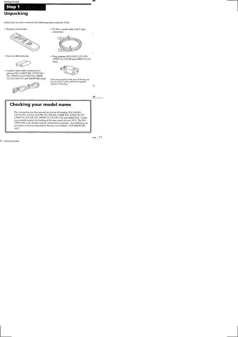
Supplied accessories
Remote commander (1) Size AA (R6) batteries (2)
75 Ω coaxial cable with F-type connectors (1) Audio/video cable (3 phono to 3 phono) (1)(SLV-
L69HF MX, L72HF PA/PC, L79HF CL/CS/PR/VZ, L89HF CL/CS/MX/VZ and
X66HF MX only)
Plug adaptor (1)(SLV-L59 CL/CS/PR, L79HF CL/ CS/PR and L89HF CL/CS only)
Design and specifications are subject to change without notice
VIDEO CASSETTE RECORDER
MICROFILM

SAFETY-RELATED COMPONENT WARNING!!
COMPONENTS IDENTIFIED BY MARK !OR DOTTED LINE WITH
MARK !ON THE SCHEMATIC DIAGRAMS AND IN THE PARTS
LIST ARE CRITICAL TO SAFE OPERATION. REPLACE THESE
COMPONENTS WITH SONY PARTS WHOSE PART NUMBERS
APPEAR AS SHOWN IN THIS MANUAL OR IN SUPPLEMENTS
PUBLISHED BY SONY.
SAFETY CHECK-OUT
After correcting the original service problem, perform the following
safety checks before releasing the set to the customer.
1.Check the area of your repair for unsoldered or poorly-soldered connections. Check the entire board surface for solder splashes and bridges.
2.Check the interboard wiring to ensure that no wires are "pinched" or contact high-wattage resistors.
3.Look for unauthorized replacement parts, particularly transistors, that were installed during a previous repair. Point them out to the customer and recommend their replacement.
4.Look for parts which, through functioning, show obvious signs of deterioration. Point them out to the customer and recommend their replacement.
5.Check the B+ voltage to see it is at the values specified.
6.Flexible Circuit Board Repairing
•Keep the temperature of the soldering iron around 270˚C during repairing.
•Do not touch the soldering iron on the same conductor of the circuit board (within 3 times).
•Be careful not to apply force on the conductor when soldering or unsoldering.
— 2 —

|
TABLE OF CONTENTS |
SERVICE NOTE |
• DI-70 (DIAL TIMER SWITCH) |
1.ERROR CODE INDICATION ········································PRINTED WIRING BOARD ·········4
•DI-70 (DIAL TIMER SWITCH)
1. GENERAL SCHEMATIC DIAGRAMS ··········
• DS-84 (TAPE OPERATION)
Index to parts and controls ······················································
PRINTED WIRING BOARD ·········
Step 1 Unpacking ·························································
• DS-84 (TAPE OPERATION)
Step 2 Setting up the remote commander ·································· 1-3
SCHEMATIC DIAGRAMS ··········
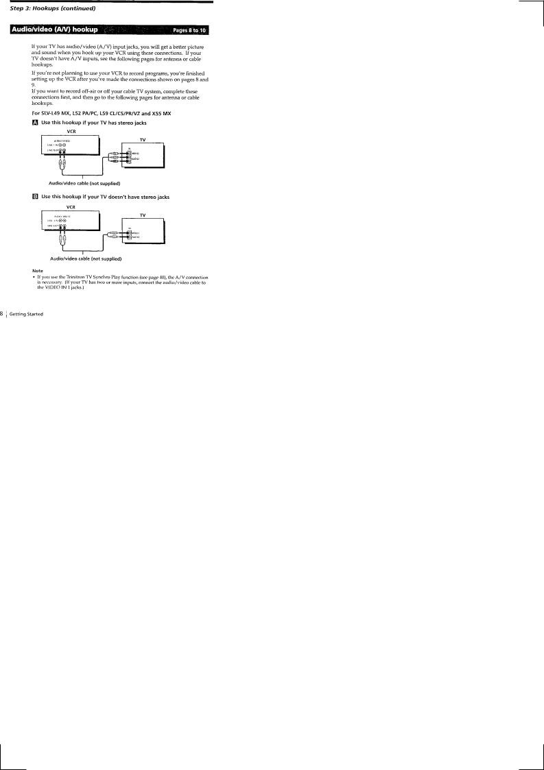
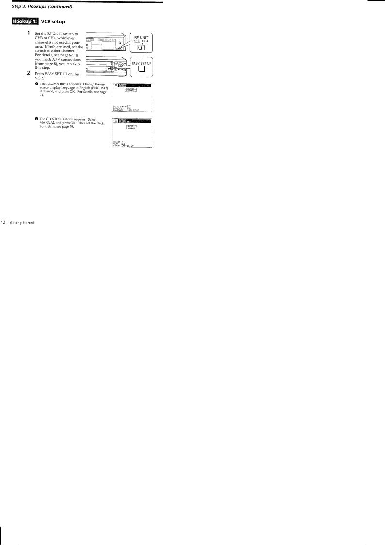
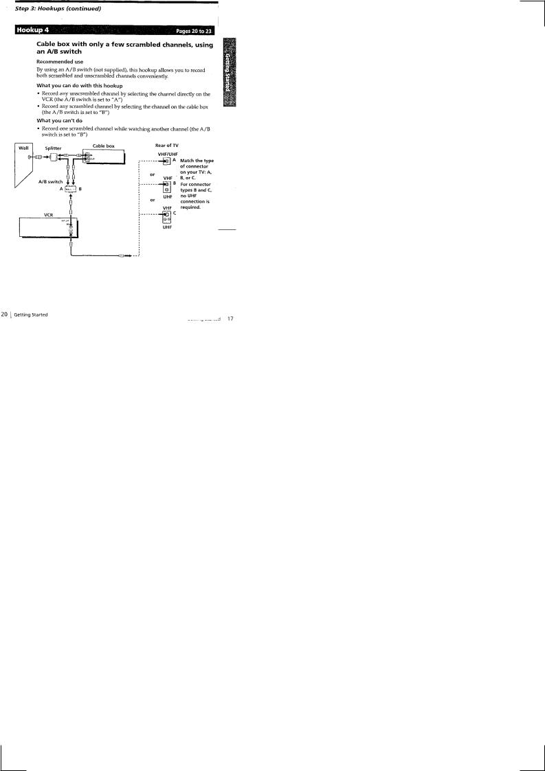
Step 3 Hookups ··························································
• JK-168 (LINE IN) PRINTED WIRING BOARD ····· 4-25 Selecting a language ························································
• JK-168 (LINE IN) SCHEMATIC DIAGRAMS ········
Setting the clock ··························································
• AR-20 (ARC) PRINTED WIRING BOARD ·········
Presetting channels ·························································
• AR-20 (ARC) SCHEMATIC DIAGRAMS ··········
Playing a tape ···························································
Recording TV programs ·······················································
5. INTERFACE, IC PIN FUNCTION
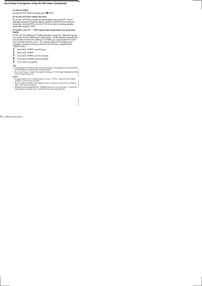
Recording TV programs using the timer ································· 1-12
DESCRIPTION
Playing/searching at various speeds ········································ 1-13 Searching for a selected point on the tape ·······························5-1. SYSTEM CONTROL — MECHANISM1-14 BLOCK
Skip-searching automatically ··················································INTERFACE (MA-341 BOARD IC160) ············1-15 Recording TV programs using the dial timer ··························5-2. SYSTEM CONTROL — SERVO1-15 PERIPHERAL
Setting the recording duration time ·········································IC160)CIRCUIT INTERFACE (MA-341 BOARD -16·······
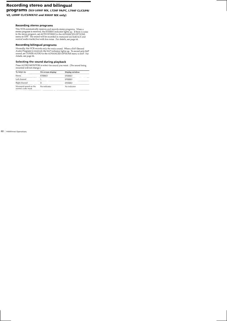
Checking/changing/canceling timer settings ···························5-3. SYSTEM CONTROL — SYSTEM1-16 CONTROL PERIPH Recording stereo and bilingual programs ································ERAL CIRCUIT INTERFACE 1-16
Adjusting the picture ························································(MA-341 BOARD IC160)
Changing menu options ·······················································5-4. SYSTEM CONTROL AND RF MODULATOR Editing with another VCR ······················································— INPUT SELECTION BLOCK INTERFACE General setup information ······················································(MA-341 BOARD IC160)
Troubleshooting ··························································5-5. SYSTEM CONTROL — VIDEO/RP BLOCK INTER
FACE (MA-341 BOARD IC160) ···············
|
5-6. SYSTEM CONTROL — AUDIO BLOCK INTERFACE |
2. DISASSEMBLY |
(MA-341 BOARD IC160) ·················· |
5-7. SERVO/SYSTEM CONTROL MICROPROCESSOR PIN 2-1. UPPER CASE, PANEL BLOCK ASSEMBLY ··············· 2-1
FUNCTIONS (MA-341 BOARD IC160) ············
2-2. DS-84, DI-70, JK-168 BOARDS ···································· 2-1
2-3. REAR PANEL ························································
2-4. |
|
6. |
ADJUSTMENTS |
|
MA-341 BOARD ······················································· |
||||
2-5. |
|
6-1. |
MECHANICAL ADJUSTMENTS |
|
MECHANISM DECK ····················································· |
||||
|
|
6-2. |
ELECTRICAL ADJUSTMENTS |
|
2-6. INTERNAL VIEWS ······················································ |
||||
|
|
1. |
PREPARATION BEFORE ADJUSTMENT ··········· |
|
2-7. CIRCUIT BOARDS LOCATION ··································· 2-5 |
||||
|
|
1-1. |
Equipment Required ····················· |
|
3. |
BLOCK DIAGRAMS |
1-2. |
Equipment Connection ···················· |
|
|
|
1-3. |
Set-up of Adjustment ····················· |
|
3-1. OVERALL BLOCK DIAGRAM ···································· 3-1 |
||||
|
|
1-4. |
Alignment Tape ······················· |
|
3-2. VIDEO BLOCK DIAGRAM ·········································· 3-3 |
||||
|
|
1-5. |
Input/Output Levels and Impedance ·············· |
|
3-3. SERVO/SYSTEM CONTROL BLOCK DIAGRAM ····· 3-5 |
|
|||
3-4. |
|
1-6. |
Adjustment Sequence ···················· |
|
AUDIO/TUNER BLOCK DIAGRAM ··························· 3-7 |
||||
|
|
2. |
POWER SUPPLY CHECK ·················· |
|
3-5. POWER BLOCK DIAGRAM ········································· 3-9 |
||||
|
|
2-1. |
Output Voltage Check (MA-341 Board) ············ |
|
4. |
PRINTED WIRING BOARDS AND |
3. |
SERVO SYSTEM CHECK ·················· |
|
|
SCHEMATIC DIAGRAMS |
3-1. RF Switching Position Adjustment (MA-341 Board) ····· 6-3 |
||
|
4. |
AUDIO SYSTEM ADJUSTMENT ·············· |
||
|
|
|||
4-1. FRAME SCHEMATIC DIAGRAM ································ 4-3 |
||||
4-2. PRINTED WIRING BOARDS AND SCHEMATIC |
4-1. |
Hi-Fi Audio System Adjustment (Hi-Fi model only) ····· 6-3 |
||
4-2. HiFi Switching Position Adjustment |
||||
|
|
|||
|
DIAGRAMS ························································· |
|||
|
• MA-341 (1/7) (VIDEO) |
|
(MA-341 Board) ······················· |
|
|
4-3. Normal Audio System Adjustment ··············· |
|||
|
|
|||
|
SCHEMATIC DIAGRAMS ················ 4-5 |
|||
|
• MA-341 (2/7) (AUDIO) |
4-3-1. ACE Head Adjustment ···················· |
||
|
4-3-2. E-E Output Level Check ··················· |
|||
|
|
|||
|
SCHEMATIC DIAGRAMS ················ 4-7 |
|||
|
• MA-341 (3/7) (SERVO/SYSCON) |
4-3-3. Frequency Response Check ·················· |
||
|
5. |
ADJUSTING PARTS LOCATION DIAGRAM ········· |
||
|
|
|||
|
SCHEMATIC DIAGRAMS ················ 4-9 |
|||
|
• MA-341 (4/7) (AUDIO PROCESS) |
7. |
REPAIR PARTS LIST |
|
|
|
|||
|
SCHEMATIC DIAGRAMS ·············· 4-11 |
|||
|
• MA-341 (5/7) (TUNER) |
7-1. |
EXPLODED VIEWS ···················· |
|
|
7-1-1. FRONT PANEL AND UPPER CASE SECTION ········ |
|||
|
|
|||
|
SCHEMATIC DIAGRAMS ·············· 4-13 |
|||
|
• MA-341 (6/7) (MODE CONTROL) |
7-1-2. CHASSIS SECTION ····················· |
||
|
7-1-3. MECHANISM DECK SECTION-1 ·············· |
|||
|
|
|||
|
SCHEMATIC DIAGRAMS ·············· 4-15 |
|||
|
• MA-341 (7/7) (POWER SUPPLY) |
7-1-4. MECHANISM DECK SECTION-2 ·············· |
||
|
7-1-5. MECHANISM DECK SECTION-3 ·············· |
|||
|
|
|||
|
SCHEMATIC DIAGRAMS ·············· 4-17 |
|||
|
|
7-2. |
ELECTRICAL PARTS LIST ················· |
|
• MA-341 (VUDEO, AUDIO, SERVO/SYSTEM CONTROL, TUNER, POWER SUPPLY)
PRINTED WIRING BOARD ············ 4-19
— 3 —

SERVICE NOTE
1.ERROR CODE INDICATION
•Error codes are indicated using the lower 5 digits in the fluorescent display tube. “At this time, Colon “:” between character is not indicated.”
 Mode code indication when the error has occurred.
|
|
Error code |
|
|
|
|
|
||
ERROR CODE |
|
|
|
|
|
|
|
|
|
|
|
|
|
|
|
|
|
|
|
0 |
No error |
|
|
|
|
|
|
|
|
|
|
|
|
|
|
|
|
|
|
1 |
Cam encoder error |
Loading direction |
|
|
|
|
|
||
|
|
|
|
|
|
|
|
|
|
2 |
Cam encoder error |
Unloading direction |
|
|
|
||||
|
|
|
|
|
|
|
|
|
|
3 |
T reel error |
|
|
|
|
|
|
|
|
|
|
|
|
|
|
|
|
|
|
4 |
S reel error |
|
|
|
|
|
|
|
|
|
|
|
|
|
|
|
|
|
|
5 |
Capstan error |
|
|
|
|
|
|
|
|
|
|
|
|
|
|
|
|
|
|
6 |
Drum error |
|
|
|
|
|
|
|
|
|
|
|
|
|
|
|
|
|
|
7 |
Error on initializing |
|
|
|
|
|
|
|
|
|
|
|
|
|
|
|
|
|
|
8 |
Cassette loading error |
|
|
|
|
|
|||
|
|
|
|
|
|
|
|
|
|
9 |
Reserve |
|
|
|
|
|
|
|
|
|
|
|
|
|
|
|
|
|
|
MODE CODE |
|
|
|
|
|
|
|
|
|
|
|
|
|
|
|
|
|
|
|
0 |
Power-on eject |
|
10 |
|
FWD x1 |
20 |
REW play |
||
|
|
|
|
|
|
|
|
|
|
1 |
Power-on initial |
|
11 |
|
FWD x2 |
21 |
Cas. loading |
||
|
|
|
|
|
|
|
|
|
|
2 |
Power-off eject |
|
12 |
|
CUE |
22 |
Tape loading |
||
|
|
|
|
|
|
|
|
|
|
3 |
Power-off stop |
|
13 |
|
PB-pause |
23 |
Power-off loading |
||
|
|
|
|
|
|
|
|
|
|
4 |
FF |
|
14 |
|
RVS-pause |
24 |
Mecha. error (Power on) |
||
|
|
|
|
|
|
|
|
|
|
5 |
REW |
|
15 |
|
RVS x1 |
25 |
Power-on eject initial |
||
|
|
|
|
|
|
|
|
|
|
6 |
REC |
|
16 |
|
RVS x2 |
26 |
Power-off eject initial |
||
|
|
|
|
|
|
|
|
|
|
7 |
RECpause |
|
17 |
|
REV |
27 |
APC REC |
||
|
|
|
|
|
|
|
|
|
|
8 |
Power-on stop |
|
18 |
|
Power-off initial |
28 |
Cas. loading |
||
|
|
|
|
|
|
|
|
|
|
9 |
PB |
|
19 |
|
Mecha. error (Power off) |
|
(No auto PB check) |
||
|
|
|
|
|
|
|
|
|
|
— 4 —

SLV-L49/L52/L59/L69HF/L72HF/L79HF/L89HF/X55/X66HF
SECTION 1 GENERAL
This section is extracted from instruction manual.
1-1
1-2
1-3
1-4

1-5
1-6
1-7
1-8
1-9
1-10

1-11

1-12

1-13
1-14
1-15
1-16
1-17
 Loading...