


KV-29FS60A
Sony KV-29FS60A, KV-29FS60B, KV-29FS60D, KV-29FS60E, KV-29FS60K SERVICE MANUAL
...
1
SERVICE MANUAL AE-5
CHASSIS
MODEL
COMMANDER DEST CHASSIS NO.
MODEL
COMMANDER DEST CHASSIS NO.
®
KV-29FS60A
RM-891 Italian SCC-Q12E-A
KV-29FS60B
RM-891 French SCC-Q13E-A
KV-29FS60D
RM-891 AEP SCC-Q11E-A
KV-29FS60E
RM-891 Spanish SCC-Q14E-A
KV-29FS60K
RM-891 OIRT SCC-Q16G-A
KV-29FS60R
RM-891 OIRT SCC-Q16H-A
KV-29FS60U
RM-891 UK SCC-Q15D-A
KV-32FS60A
RM-891 Italian SCC-Q12F-A
KV-32FS60B
RM-891 French SCC-Q13F-A
KV-32FS60D
RM-891 AEP SCC-Q11F-A
KV-32FS60E
RM-891 Spanish SCC-Q14F-A
MICROFILM
TRINITRON
®
COLOR TV
2
[PICTURE TUBE]
KV-29FS60
FD Trinitron
Approx. 72 cm (29 inches)
(Approx. 68 cm picture measured
diagonally)
102 degree deflection
KV-32FS60
FD Trinitron
Approx. 82 cm (32 inches)
(Approx. 76 cm picture measured
diagonally)
102 degree deflection
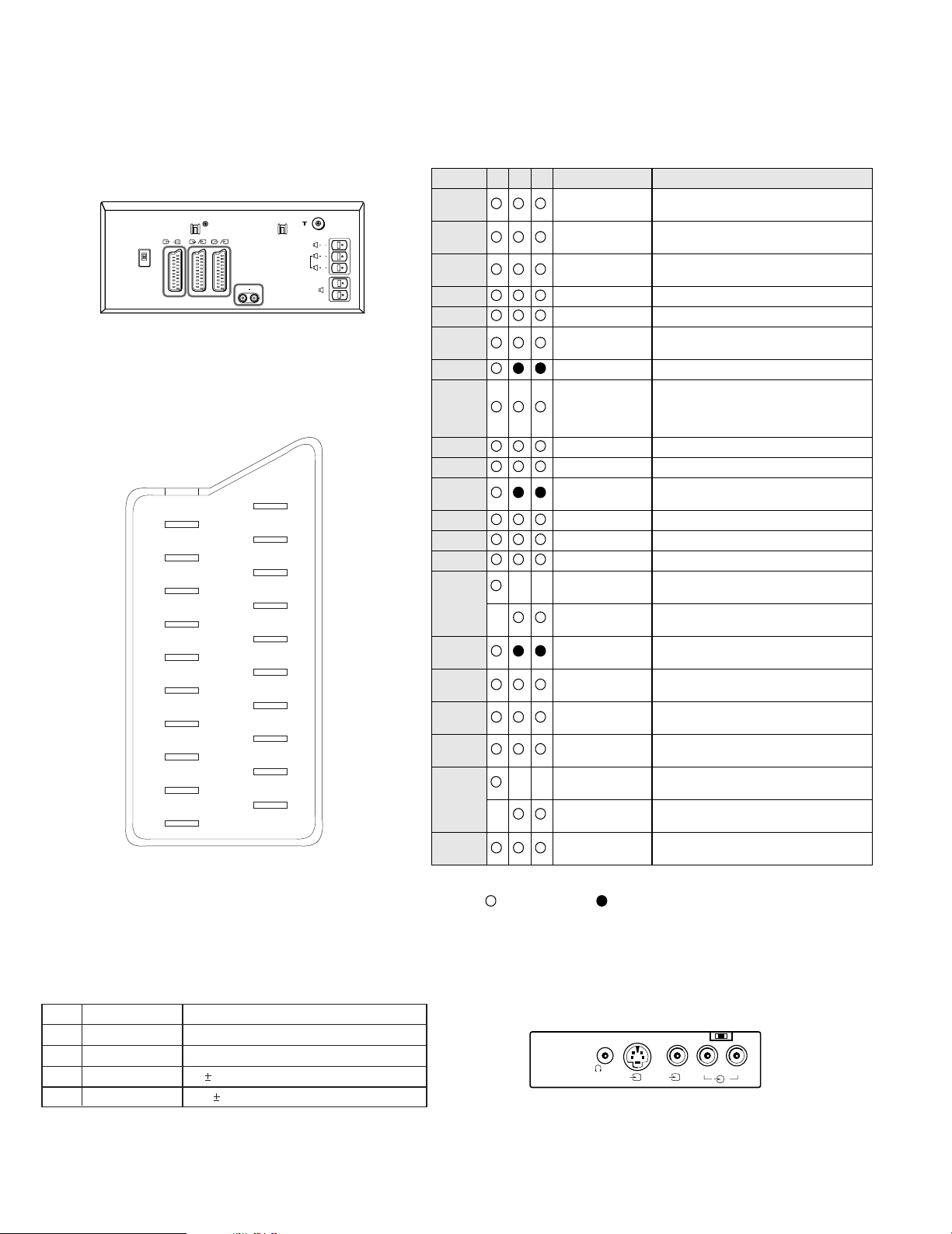
Input/Output Terminals
[REAR]
21-pin Euro connector (CENELEC standard).
- Inputs for Audio and Video signals.
- Inputs for RGB.
- Outputs of TV Video and Audio signals.
21-pin Euro connector
- Inputs for Audio and Video signals.
- Inputs for S video.
- Outputs forVideo and Audio signals (selectable).
21-pin Euro connector
- Inputs for Audio and Video signals.
- Inputs for S video.
External speaker terminals : 2-pin DIN (5)
[FRONT]
3
Video output - phono jack
3
Audio inputs - phono jacks
3
S Video input - 4 pin DIN
Headphone jack : stereo minijack
Sound output 2x25W (Music Power)
Power requirements 220 - 240V
Dimensions
KV-29FS60 Approx 738 x 588 x 507 mm (w/h/d)
KV-32FS60 Approx 867 x 564 x 558 mm (w/h/d)
Weight
KV-29FS60 Approx 55kg
KV-32FS60 Approx 68kg
Supplied accessories RM-891 Remote Commander (1)
IEC designated R6 battery (2)
Other features NICAM*, FASTEXT, TOPTEXT
* (KV-29FS60B/29FS60E/29FS60K/
29FS60U/32FS60B/32FS60E only)
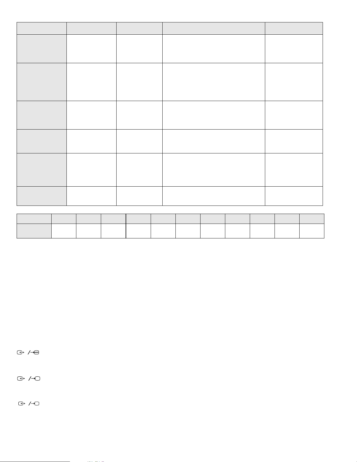
ITEM MODEL Television System Stereo System Channel Coverage Color System
Italian
B/G/H,D/K GERMAN Stereo
ITALIA VHF : A-H2 (C) UHF : 21-69 PAL
B/G/H VHF : E2-E12 UHF : E21-E69
CABLE TV (1) : S1-S41
CABLE TV (2) : S01-S05,M1-M10,U1-U10
DK VHF : R01-R12 UHF : R21-R69
PAL, SECAM
NTSC4.43, NTSC3.58
(VIDEO IN)
French
B/G/H, D/K,L,I GERMAN/NICAM
Stereo
L VHF : F02-F10 UHF : F21-F60
CABLE : B-Q B/G/H VHF : E2-E12
UHF : E21-E69
CABLE TV (1) : S1-S41
CABLE TV (2) : S01-S05, M1-M10, U1-U10
ITALIA VHF : A-H2 (C) UHF : 21-69
I UHF : B21-B69
PAL, SECAM
NTSC4.43, NTSC3.58
(VIDEO IN)
AEP
B/G/H, D/K GERMAN Stereo
PAL B/G/H/ VHF : E2-E12 : E21-E69
CABLE TV (1) : S1-S41
CABLE TV (2) : S01-S05, M1-M10, U1-U10
ITALIA VHF : A-H2 (C) UHF : 21-69
D/K VHF : R01-R12 UHF : R21-R69
PAL, SECAM
NTSC4.43, NTSC3.58
(VIDEO IN)
Spanish
B/G/H, D/K GERMAN/NICAM
Stereo
PAL B/G/H/ VHF : E2-E12 : E21-E69
CABLE TV (1) : S1-S41
CABLE TV (2) : S01-S05, M1-M10, U1-U10
ITALIA VHF : A-H2 (C) UHF : 21-69
PAL, SECAM
NTSC4.43, NTSC3.58
(VIDEO IN)
OIRT
B/G/H, D/K
KV-29FS60K
GERMAN/NICAM
Stereo
KV-29FS60R
GERMAN Stereo
B/G/H/ VHF : E2-E12 UHF : E21-E69
CABLE TV (1) : S1-S41
D/K VHF : R01-R12 UHF : R21-R69
PAL, SECAM
NTSC4.43, NTSC3.58
(VIDEO IN)
UK
I NICAM Stereo UHF : B21-B69
PAL
NTSC4.43, NTSC3.58
(VIDEO IN)
MODEL 29FS60A 29FS60B 29FS60D 29FS60E 29FS60K 29FS60R 29FS60U 32FS60A 32FS60B 32FS60D 32FS60E
Power
Consumption
149Wh 148Wh 148Wh 148Wh 148W 148W 148Wh 144Wh 149Wh 149Wh 149Wh
1
2
S
3
S
3
WARNING
(KV-29FS60U only)
The flexible mains lead is supplied connected to a
B.S. 1363
fused plug
having a fuse of
5 AMP
capacity. Should the fuse need to be replaced,
use a
5 AMP FUSE
approved by
ASTA
to
BS 1362
, ie one that carries the
mark.
IF THE PLUG SUPPLIED WITH THIS APPLIANCE IS NOT SUITABLE
FOR THE OUTLET SOCKETS IN YOUR HOME, IT SHOULD BE CUT
OFF AND AN APPROPRIATE PLUG FITTED. THE PLUG SEVERED
FROM THE MAINS LEAD MUST BE DESTROYED AS A PLUG WITH
BARED WIRES IS DANGEROUS IF ENGAGED IN A LIVE OUTLET
SOCKET.
When an alternative type of plug is used it should be fitted with a
5 AMP
FUSE
, otherwise the circuit should be protected by a
5 AMP FUSE
at the
distribution board.
ASA
T
How to replace the fuse.
Open the fuse compartment with
a screwdriver blade and replace
the fuse.
FUSE
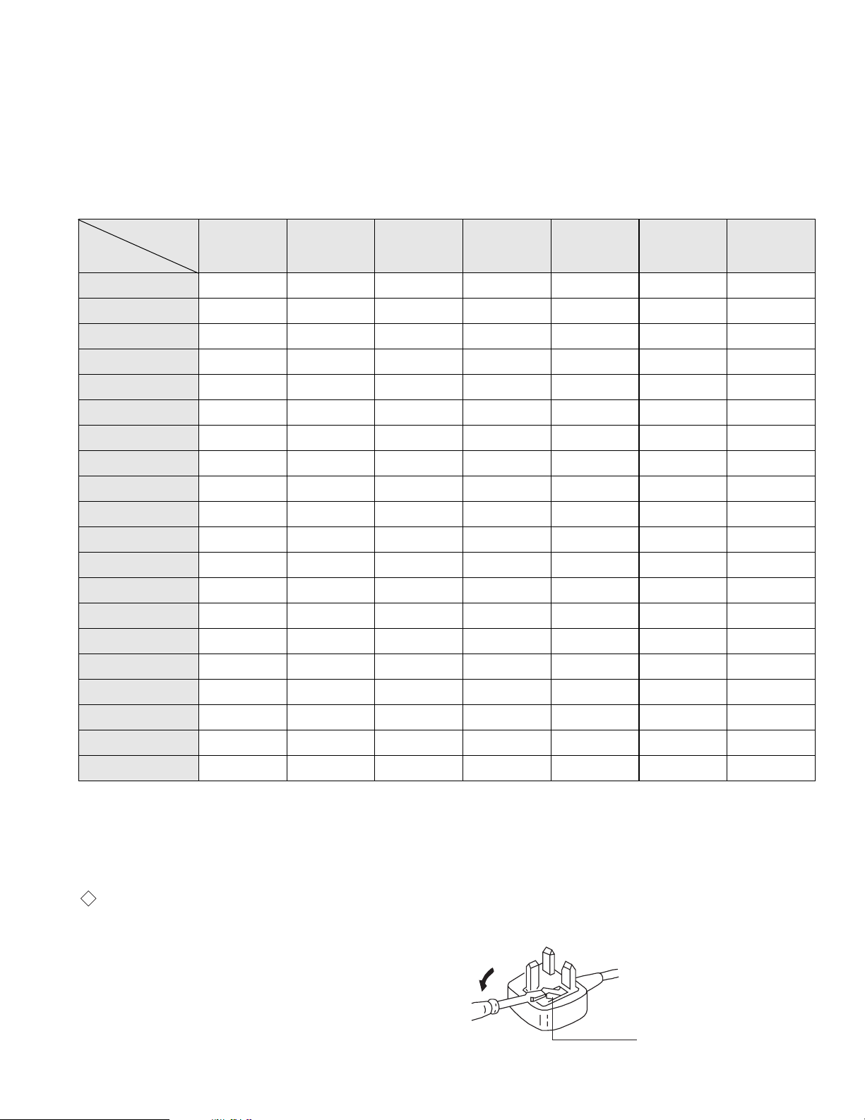
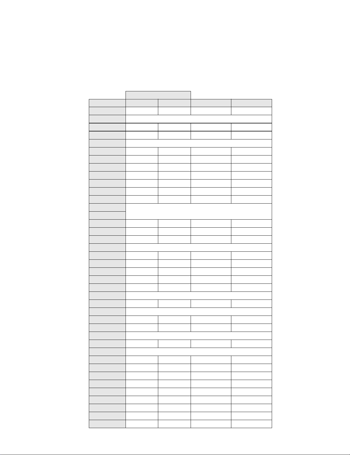
Model Name
Item
KV -29FS60A
KV -32FS60A
KV -29FS60B
KV -32FS60B
KV -29FS60D
KV -32FS60D
KV -29FS60E
KV -32FS60E
KV -29FS60K KV-29FS60R KV-29FS60U
Pal Comb
ON ON ON ON ON ON ON
PIP
OFFOFFOFFOFFOFFOFFOFF
RGB Priority
ON ON ON ON ON ON ON
Woofer Box
OFFOFFOFFOFFOFFOFFOFF
Scart 1
ON ON ON ON ON ON ON
Scart 2
ON ON ON ON ON ON ON
Front in (3)
ON ON ON ON ON ON ON
Scart 4
ON ON ON ON ON ON ON
Projector
OFFOFFOFFOFFOFFOFFOFF
AKB in 16:9 mode
ON ON ON ON ON ON ON
Norm B/G
ON ON ON ON ON ON OFF
Norm I
OFF ON OFF OFF OFF OFF ON
Norm D/K
ON ON ON ON ON ON OFF
Norm AUS
OFFOFFOFFOFFOFFOFFOFF
Norm L
OFF ON OFF OFF OFF OFF OFF
Norm SAT
OFFOFFOFFOFFOFFOFFOFF
Norm M
OFFOFFOFFOFFOFFOFFOFF
Teletext
ON ON ON ON ON ON ON
Nicam Stereo
OFF ON OFF ON ON OFF ON
Language Preset
Italian French German Spanish OIRT OIRT English
[RM-891]
Remote control system Infrared control
Power requirements 3V dc
2 batteries IEC designation
R6 (size AA)
Dimensions Approx 210x56x24mm (w/h/d)
Weight Approx 110g (Not including battery)
Design and specifications are subject to change without notice.
4
21 pin connector
Connected Not Connected (open) * at 20Hz - 20kHz
L/G/S/I R/D/D/D
S
3
3
3
R/D/D/D
L/G/S/I
R/D/D/D
L/G/S/I
2
S
2
1
3
S
3
1/
S
G
S
19
17
15
13
11
9
7
5
3
1
20
18
16
14
12
10
8
6
4
2
21
Pin No 1 2 4 Signal Signal level
1
Audio output B
(right)
Standard leve l : 0.5V rms
Output impedence : Less than 1kohm*
2
Audio output B
(right)
Standard leve l : 0.5V rms
Output impedence : More than 10kohm*
3
Audio output A
(left)
Standard leve l : 0.5V rms
Output impedence : Less than 1kohm*
4
Ground (audio)
5
Ground (blue)
6
Audio input A
(left)
Standard leve l : 0.5V rms
Output impedence : More than 10kohm*
7
Blue input 0.7 +/- 3dB, 75 ohms positive
8
Function select
(AV control)
High state (9.5-12V) : Part mode
Low state (0-2V) : TV mode
Input impedence : More than 10K ohm s
Input capacitance : Less than 2nF
9
Ground (green)
10
Open
11
Green Green signal : 0.7 +/- 3dB, 75 ohms,
positive
12
Open
13
Ground (red)
14
Ground (blanking)
15
_ _ Red input 0.7 +/- 3dB, 75 ohms, positive
_ (S signal Chroma
input)
0.3 +/- 3dB, 75 ohms, positive
16
Blanking input
(Ys signal)
High state (1-3V) Low state (0-0.4V)
Input impedence : 75 ohms
17
Ground (video
output)
18
Ground (video
input)
19
Video output 1V +/- 3dB, 75ohms, positive sync 0.3V
(-3+10dB)
20
_ _ Video input 1V +/- 3dB, 75ohms, positive sync 0.3V
(-3+10dB)
_ Video input
Y (S signal)
1V +/- 3dB, 75ohms, positi ve sync 0.3V
(-3+10dB)
21
Common ground
(plug, shield)
Signal
Ground
Ground
Y (S signal) input
C (S signal) input
Pin No.
1
2
3
4
Signal Level
1V 3dB 75 ohm, positive Sync. 0.3V -3 + 10dB
0.3V 3dB 75 ohm, positive Sync.
5
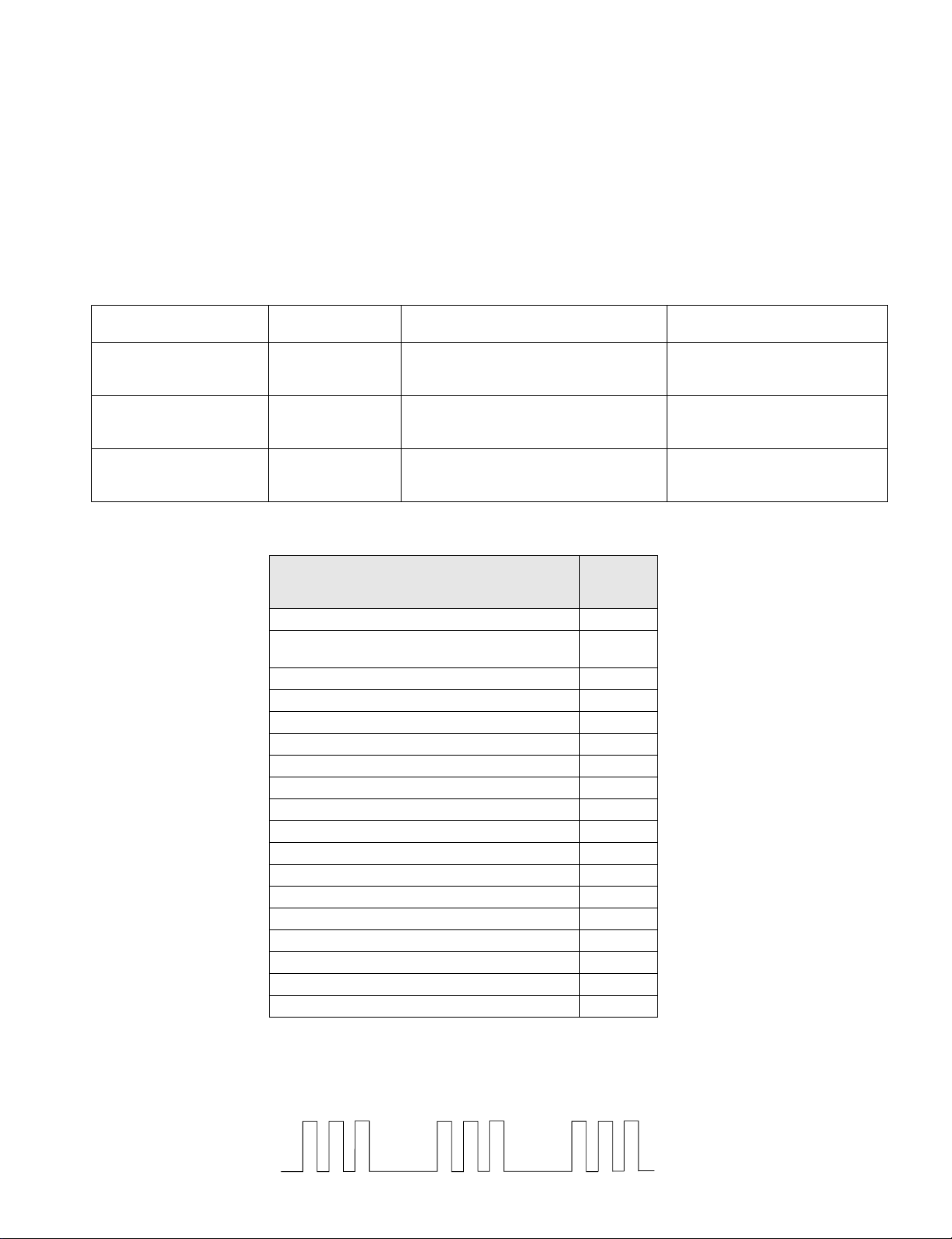
AE-5 SELF DIAGNOSTIC SOFTWARE
The identification of errors within the AE-5 chassis is triggered in one of two ways :- 1: Busy or 2: Device failure to respond to IIC. In the event
of one of these situations arising the software will first try to release the bus if busy (Failure to do so will report with continuous flashing LED) and
then communicate with each device in turn to establish if a device is f a ulty. If a device is found to be faulty the relevant device number will be dis-
played through the LED (Series of flashes which must be counted) See table 1., non fatal errors are reported using this method.
ERROR
LED
ERROR
COUNT
No error 00
Not allowed (may be confused with Sircs response
flash!)
01
Over Current Protection 02
Over Voltage Protection 03
Vertical Protection 04
AKB 05
H - Protection 06
Speaker Protection 07
General IIC Line 0 error 08
MEGATEXT 09
NVM 10
Main colour decoder 11
Feature Box 12
D/A converter 13
Backend 14
Multi sound processor 15
Auto Wide 16
External RAM 17
StBy LED
ON ON ON
OFF OFF
Flash Timing Example : e.g. error number 3
Diagnostic Item
Description
No of times Standby
LED Flashes
Probable cause
Location
Detected Symptoms
Power does not turn on Does not light Power cord is not plugged in
Fuse is burned out
Power does not come on
No power is supplied to the TV
AC power supply is faulty
+B Overcurrent (OCP) 2 times H.OUT (Q6803/6804) is shorted. (D Board)
Linearity FET (Q6806) is shorted. (D Board)
IC6604 Power IC is shorted. (D Board)
Power does not come on
Load on power line has shorted
Vertical Deflection stopped 4 times +15V is not supplied R6835 open (D Board)
-15V is not supplied R6834 open (D Board)
IC6700 is shorted (D Board)
Vertical deflection pulse has stopped
Power line has shorted

6
ERROR DETECTION MONITOR
Device acknowledge is used to check IIC errors. Device acknowledge is checked by sending an IIC start sequence during CRT power on. Each
device is checked three times, if there is no acknowledge after every attempt, it will be regarded as an error.
There are three steps to check errors
1. IIC line 0
If all devices except the NVM have errors, IIC line 0 error is displayed
2. Board check
If all devices mounted on one board have errors, board error is displayed
3. Each device check
If IIC line error and board error are not detected then the device with an error is displayed
The detected errors can be displayed as follows:
1. Error Monitor Menu
2. Error Reader
1. ERROR MONITOR MENU
The error monitor menu is displayed by selecting TT33. The following menu will be displayed:
ERROR MONITOR
Operating Time :
930360h 15h
Saved Errors :
1. 100h = A-Board
2. 401h = BP-B CXD2069 MID
3. 704h = J-B TDA9320 Main Col Dec
4. 000h = no error occured
5. 000h = no error occured
Actual Error :
New error code sequence is starting
Ignore Errors : [off]
7
2. ERROR READER DISPLAY
The error reader display is connected to the service connector to read actual error codes. The part number for the error reader display is S-188-900-10.
Once an error has been detected it will then be displayed on the two digit error reader. The errors displayed refer to the following table :
Send Data to Error Reader
Error Code Data high Data Low Error type Function
00 00h - f0h no device
Gen.IIC Error
00 01h f0h 01h IIC 0 line
00 02h f0h 02h IIC 1 line not used
Board Error
01 00h f1h 00h A Board
02 00h f2h 00h B1 Board
03 00h f3h 00h B2 Board
04 00h f4h 00h BP Board
05 00h f5h 00h D1 Board
06 00h f6h 00h E Board
07 00h f7h 00h J Board
Device Error
A Board
01 01h f1h 01h CXA1875 Port Expander
01 02h f1h 02h TU1326 Main Tuner
01 03h f1h 03h TU1350 Sub Tuner
B1 Board
02 01h f2h 01h P83C654 Feature Box
02 02h f2h 02h SDA9280 D/A Converter
B2 Board
03 01h f3h 01h SAA4977 Basic
03 02h f3h 02h SAA4950 Memory
BP Board
04 01h f4h 01h CXD2069 MID
D1 Board
05 01h f5h 01h CXA8070 Dynamic Conv.
05 02h f5h 02h CXA1875 Port Expander
E Board
06 01h f6h 01h CXD2100 Backen d
J Board
07 01h f7h 01h CXD2057 Auto Wide
07 02h f7h 02h SDA9288 PIP
07 03h f7h 03h TDA9320 Sub Colour
07 04h f7h 04h TDA9320 Main Colour
07 05h f7h 05h CXA1875 Sub Sound
07 06h f7h 06h TDA7309 HP Amp
07 07h f7h 07h TEA6422DT Audio SW
07 08h f7h 08h MSP3410D Sound Proc
07 09h f7h 09h TC9337F Sound DSP

8
TABLE OF CONTENTS
CAUTION
SHORT CIRCUIT THE ANODE OF THE PICTURE TUBE AND THE
ANODE CAP TO THE METAL CHASSIS, CRT SHIELD, OR THE
CARBON PAINTED ON THE CRT, AFTER REMOVAL OF THE
ANODE CAP
WARNING !!
AN ISOLATING TRANSFORMER SHOULD BE USED DURING ANY
SERVICE WORK TO AVOID POSSIBLE SHOCK HAZARD DUE TO
LIVE CHASSIS. THE CHASSIS OF THIS RECEIVER IS DIRECTLY
CONNECTED TO THE POWER LINE.
SAFETY-RELATED COMPONENT WARNING !!
COMPONENTS IDENTIFIED BY SHADING AND MARKED ON
THE SCHEMATIC DIAGRAMS, EXPLODED VIEWS AND IN THE
PARTS LIST ARE CRITICAL FOR SAFE OPERATION. REPLACE
THESE COMPONENTS WITH SONY PARTS WHOSE PART NUMBERS
APPEAR AS SHOWN IN THIS MANUAL OR IN SUPPLEMENTS
PUBLISHED BY SONY.
ATTENTION
APRES AVOIR DECONNECTE LE CAP DE’LANODE,
COURT-CIRCUITER L’ANODE DU TUBE CATHODIQUE ET
CELUI DE L’ANODE DU CAP AU CHASSIS METALLIQUE
DE L’APPAREIL, OU AU COUCHE DE CARBONE PEINTE
SUR LE TUBE CATHODIQUE OU AU BLINDAGE DU TUBE
CATHODIQUE.
ATTENTION !!
AFIN D’EVITER TOUT RISQUE D’ELECTROCUTION PROVENANT
D’UN CHÁSSIS SOUS TENTION, UN TRANSFORMATEUR
D’ISOLEMENT DOIT ETRE UTILISÈ LORS DE TOUT DÈPANNAGE.
LE CHÁSSIS DE CE RÈCEPTEUR EST DIRECTMENT RACCORDÈ
Á L’ALIMENTATION SECTEUR.
ATTENTION AUX COMPOSANTS RELATIFS Á LA
SÈCURITÈ !!
LES COMPOSANTS IDENTIFIÈS PAR UNE TRAME ET PAR UNE
MARQUE SUR LES SCHÈMAS DE PRINCIPE, LES VUES
EXPLOSÈES ET LES LISTES DE PIECES SONT D’UNE IMPORTANCE
CRITIQUE POUR LA SÈCURITÈ DU FONCTIONNEMENT, NE LES
REMPLACER QUE PAR DES COMPSANTS SONY DONT LE NUMÈRO
DE PIÈCE EST INDIQUÈ DANS LE PRÈSENT MANUEL OU DANS
DES SUPPLÈMENTS PUBLIÈS PAR SONY.
Section Title Page Section Title Page
Warning and Caution .....................3
Self-Diagnostic Function .....................5
1. GENERAL
Overview .....................9
Installation .....................10
Advanced Operations .....................11
Teletext .....................16
2. DISASSEMBLY
2-1. Rear Cover Removal .....................17
2-2. Chassis Assy Removal .....................17
2-3. Service Position .....................17
2-4. U Board Removal .....................17
2-5. J Board Removal .....................18
2-6. J Shield Removal .....................18
2-7. B1 Board Removal .....................18
2-8. Picture Tube Removal .....................19
Removal and Replacement of the
Main-Bracket bottom plates ........ .............20
3. SET-UP ADJUSTMENTS
3-1. Beam Landing .....................21
3-2. Convergence .....................22
3-3. Focus .....................24
3-4. Screen [G2] White Balance .....................24
4. CIRCUIT ADJUSTMENTS
4-1. Electrical Adjustments .....................26
4-2. Volume Electrical Adjustments .....................32
4-3. Test Mode 2 .....................33
5. DIAGRAMS
5-1. Block Diagram (1) .....................35
Block Diagram (2) .....................40
Block Diagram (3) .....................45
Block Diagram (4) .....................50
5-2. Circuit Board Location .....................55
5-3. Schematic Diagrams and
Printed Wiring Boards .....................55
* C Board .....................57
* J Board .....................65
* U Board .....................74
* A Board .....................81
* BP Board .....................85
* VM Board .....................92
* B1 Board .....................95
* D1 Board .....................99
* F Board .....................103
* F1 Board .....................106
* M Board .....................107
* E Board .....................111
* D Board .....................116
* H1 Board .....................122
5-4. Semiconductors .....................125
5-5. IC Blocks .....................128
6. EXPLODED VIEWS
6-1. Chassis .....................129
6-2. Picture Tube .....................131
7. ELECTRICAL PARTS LIST
.....................133
9
SECTION 1
GENERAL
The operating instructions mentioned here are partial abstracts from the Operating
Instruction Manual. The page numbers of the Operating Instruction Manual remain
as in the manual.
28
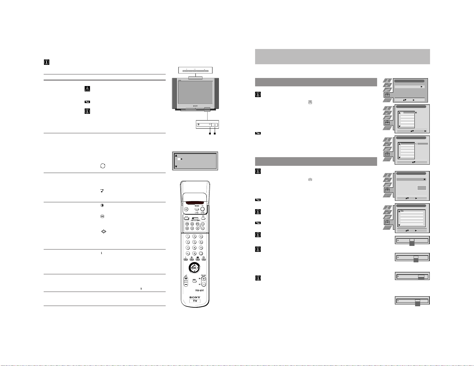
Overview
This section briefly describes the buttons and controls on the TV set and the Remote Control.
Open the flaps at the front and back of his Instruction Manual for detailed illustrations.
For more information refer to the page numbers given in the overview.
Remote Control
Symbol Description See page
1 TV
I/
u TV: standby mode on/off . . . . . . . . . . . . . . . . . . . . . . . . . . . . . . . . . . . . . 32
2
+
TV: on-screen display . . . . . . . . . . . . . . . . . . . . . . . . . . . . . . . . . . . . . . . . 32
Teletext: index page . . . . . . . . . . . . . . . . . . . . . . . . . . . . . . . . . . . . . . . . . . 42
3
Selecting of input source . . . . . . . . . . . . . . . . . . . . . . . . . . . . . . . . . . . . . 44
R Teletext: Freezing a subpage . . . . . . . . . . . . . . . . . . . . . . . . . . . . . . . . . . 42
4
Å/a
PIP: Swapping the screens . . . . . . . . . . . . . . . . . . . . . . . . . . . . . . . . . . . . 41
5 > PIP: Selecting the source . . . . . . . . . . . . . . . . . . . . . . . . . . . . . . . . . . . . . . 41
6
´/´
PIP: Switching on and off . . . . . . . . . . . . . . . . . . . . . . . . . . . . . . . . . . . . . 41
7 1, 2, … 9, 0 Number buttons . . . . . . . . . . . . . . . . . . . . . . . . . . . . . . . . . . . . . . . . . . . . 32
8
Back to the channel last selected . . . . . . . . . . . . . . . . . . . . . . . . . . . . . . . 32
9 Selecting of screen format . . . . . . . . . . . . . . . . . . . . . . . . . . . . . . . . . . . . 32
0
No function on this set
!¡ Joystick for menu selection . . . . . . . . . . . . . . . . . . . . . . . . . . . . . . . . . . . 31
Press OK to confirm
!™ MENU Switching on and off of Menu system . . . . . . . . . . . . . . . . . . . . . . . . . . 31
!£ PROGR +/– TV: Channel selection up- and downwards . . . . . . . . . . . . . . . . . . . . . 32
Teletext: Page selection up-and downwards . . . . . . . . . . . . . . . . . . . . . 42
!¢ ¸ +/– Volume control . . . . . . . . . . . . . . . . . . . . . . . . . . . . . . . . . . . . . . . . . . . . . . 32
!∞
Picture mode . . . . . . . . . . . . . . . . . . . . . . . . . . . . . . . . . . . . . . . . . . . . . . . 32
!§
Equaliser mode . . . . . . . . . . . . . . . . . . . . . . . . . . . . . . . . . . . . . . . . . . . . . 32
!¶
-/--
Selection of double digit channel numbers . . . . . . . . . . . . . . . . . . . . . . 32
!•
Freezing of TV picture . . . . . . . . . . . . . . . . . . . . . . . . . . . . . . . . . . . . . . . 32
!ª No function on this set
@º
f
Teletext: Switching on . . . . . . . . . . . . . . . . . . . . . . . . . . . . . . . . . . . . . . . . 42
@¡
;
TV: Selecting of TV mode . . . . . . . . . . . . . . . . . . . . . . . . . . . . . . . . . . . . . 32
Teletext: Switching off . . . . . . . . . . . . . . . . . . . . . . . . . . . . . . . . . . . . . . . 42
@™
¤
Muting of sound on/off . . . . . . . . . . . . . . . . . . . . . . . . . . . . . . . . . . . . . . 32
@£ VIDEO
I/
u VCR: Standby mode . . . . . . . . . . . . . . . . . . . . . . . . . . . . . . . . . . . . . . . . . 45
Buttons under cover
@¢
˚
Displaying of the time . . . . . . . . . . . . . . . . . . . . . . . . . . . . . . . . . . . . . . . 32
@∞ CH +/– VCR operation . . . . . . . . . . . . . . . . . . . . . . . . . . . . . . . . . . . . . . . . . . . . . . 45
VTR 1 2 3 4 MDP Video equipment selector
0 z ) p P r Buttons for VCR operation
@§
?
Resetting of picture setting . . . . . . . . . . . . . . . . . . . . . . . . . . . . . . . . . . . 32
33
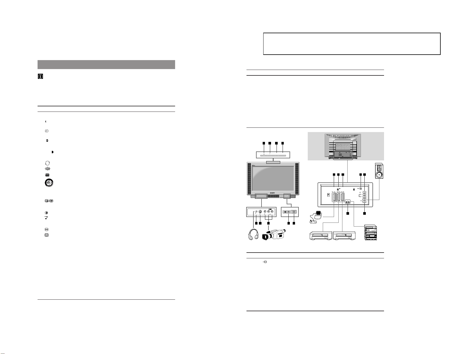
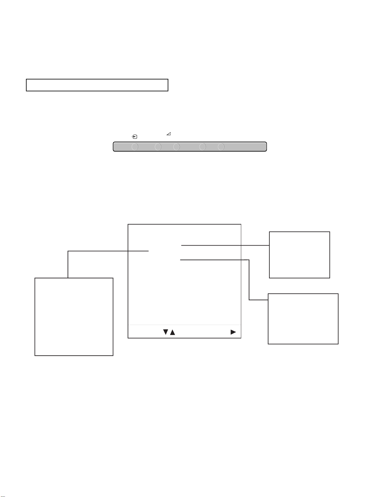
TV-set – front and top
Symbol Description See page
A
2
Headphone jack . . . . . . . . . . . . . . . . . . . . . . . . . . . . . . . . . . . . . . . . . . 54
B q 3 S-video input jack . . . . . . . . . . . . . . . . . . . . . . . . . . . . . . . . . . . . . . . . 52
C … 3,
≤
3 Phono video/audio inputs . . . . . . . . . . . . . . . . . . . . . . . . . . . . . . . . 52
D u Indicator for Standby mode . . . . . . . . . . . . . . . . . . . . . . . . . . . . . . . 37
E U Power switch . . . . . . . . . . . . . . . . . . . . . . . . . . . . . . . . . . . . . . . . . . . . 37
F … Selecting input source . . . . . . . . . . . . . . . . . . . . . . . . . . . . . . . . . . . . 52
G ¸ +/– Volume control . . . . . . . . . . . . . . . . . . . . . . . . . . . . . . . . . . . . . . . . . . 37
H PROGR +/– Channel selection up- and downwards . . . . . . . . . . . . . . . . . . . . . . 37
I CONTROL Control panel: Switching on/off . . . . . . . . . . . . . . . . . . . . . . . . . . . . 37
TV-set – rear
Symbol Description See page
J
Y
1/ 1 21-pin Euro connector (Scart) . . . . . . . . . . . . . . . . . . . . . . . . . . . . . . 52
K
Y
2/
j
2 21-pin Euro connector (Scart) . . . . . . . . . . . . . . . . . . . . . . . . . . . . . . 52
L
Y
3/
j
3 21-pin Euro connector (Scart) . . . . . . . . . . . . . . . . . . . . . . . . . . . . . . 52
M
˘
Aerial socket . . . . . . . . . . . . . . . . . . . . . . . . . . . . . . . . . . . . . . . . . . . . 35
N R/D/D/D, L/G/S/I, External speaker terminals . . . . . . . . . . . . . . . . . . . . . . . . . . . . . . . . 34
|
,
|
S,
|
C (Centre, Surround)
O L/G/S/I
™
Left and right speaker terminals . . . . . . . . . . . . . . . . . . . . . . . . . . . . 34
R/D/D/D
P
|
L/G/S/I Audio phono jacks . . . . . . . . . . . . . . . . . . . . . . . . . . . . . . . . . . . . . . . 54
R/D/D/D
R/D/D/D
L/G/S/I
L/G/S/I R/D/D/D
S
3
3
3
ED
OP
M NLKJ
A B C
+
–
+
–
PROGR
CONTROL
F G H I
R/D/D/D
L/G/S/I
R/D/D/D
L/G/S/I
2
S
2
1
3
S
3
1/
S
G
S
10
31
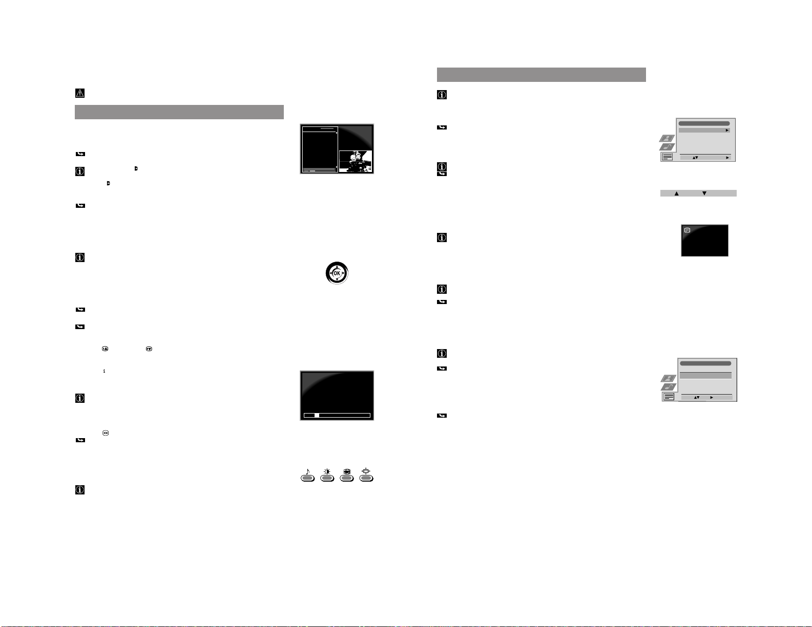
First Time Operation
Step 2 Basic Presetting
A The Menu System
Your TV uses an on-screen menu system to guide you through the operations.
Use the following buttons on the Remote Control to operate the menu system:
•
Press MENU !™ to switch the menu on and off.
•
Use “, ”, 4, $ of the joystick !¡ to select within the menu system.
•
Press OK to store.
•
When menu is switched off:
Press “ to return to the last menu screen.
C Automatic Tuning In of Channels
•
Push the joystick !¡ to ” for more than 2 sec..
After all available channels are stored, the TV goes back to the programme
position with which you started the automatic tuning. Your TV is now ready
for use.
v
To stop the automatic tuning: Press OK !¡.
v
If you wish to change the sequence of the stored channels, go to
Sorting Programme Positions in Advanced Presetting.
v
If you need to change or repeat the tuning afterwards (e.g. when you move
house) : select the menu Auto Tuning in the Set Up
menu.
1 Press the MENU !™ button.
The menu Language/Country appears on the screen.
2 Push the joystick !¡ to ”. Push the joystick !¡ to $ to select the language.
Press OK !¡.
The menus appear in the selected language.
3 Push the joystick !¡ to $ to select Country. Push the joystick !¡ to ”.
4 Select the country in which you will operate the TV set using $ or 4 .
Select Off if you wish an automatic tuning without ACI (fast presetting with a
given channel sequence).
•
Confirm by pressing OK !¡.
The menu Auto Tuning appears.
B Selecting Language and Country
Language/Country
Language
Country
Select: Enter:
English
Off
Language/Country
Language
Country
Select: Enter:
Language/Country
Language
Country
Select Country:
Confirm: OK
English
Off
Austria
Belgium
Bulgaria
Czech Rep.
Denmark
Finland
English
Off
Set Up
Auto Tuning
Programme Sorting
AV Preset
Installation
Select:
Start Auto Tuning:
Start
1
2
3
4
5
CO2
CO3
CO4
CO7
CO8
Searching
35
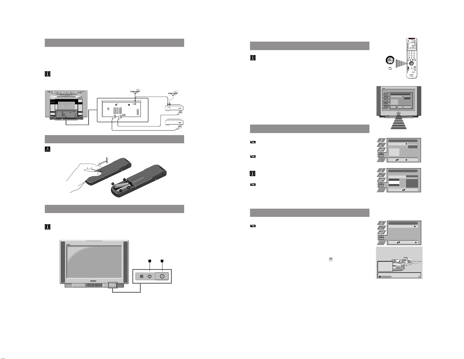
B Connecting the TV Set
1 Connect the TV set to the mains socket (220-240 V. AC, 50 Hz).
2a Connect a conventional aerial cable to the socket marked ˘ M on the rear of the TV set
or
2b Connect your Satellite Receiver to one of the Scart connectors J K L of the TV set.
When connecting a VCR to your TV set:
We recommend that you use the preset function Manual Programme Preset (page 38) to tune
in the VCR signal to programme position 0.
First Time Operation
Installation
C Inserting the Batteries into the Remote Control
Make sure to insert the batteries using the correct polarities.
Dispose of exhausted batteries according to your local regulations.
D Switching on the TV Set
•
Press the switch U E at the front of the TV set.
If the standby mode indicator u D on the TV is lit, press TV I/u 1 on the
Remote Control to switch on the TV set.
R/D/D/D
L/G/S/I
R/D/D/D
L/G/S/I
OUT IN
VIDEO
SAT
ED
11
32
Step 3 Basic TV operation
This section explains the most important functions for the daily use of your TV
set. When using the control panel on the top of the TV set, first press CONTROL
I, then F, G or H.
Function Operation
Switching on/off
•
Press U E on the TV set.
To save energy, we recommend to switch off the
TV completely when set is not in use.
Switching off temporarily
•
Press TV I/
u 1.
(Standby mode) TV is now in standby mode. Indicator u D lights
up.
After 15 min. without any TV signal and no
pressing of a button, the TV automatically goes into
standby mode.
Switch on from standby
•
Press TV I/
u 1
, PROGR +/– !£ H or any number
mode button 7.
Selecting channels
•
Press PROGR +/- !£ H or the number buttons 7.
For a double
digit number first press -/--
!¶
, then
the two number buttons.
Using the Channel
•
Press OK !¡.
overview Push to $ or 4 to select a channel, push to z to
confirm.
Going to the channel
•
Press 8.
last selected
Adjusting the volume
•
Press ¸ + or – !¢ G.
Muting the sound
•
Press
¤
@™ to switch sound off or on.
Selecting Equaliser mode
•
Press repeatedly !§ to select one of the
(See also page 39) following modes: Personal, Vocal, Jazz,
Rock, Pop or Flat
Selecting Picture mode
•
Press repeatedly !∞ to select one
(see also page 38) of the following modes: Personal, Movie or Live.
Freezing the picture
•
Press !• if you wish to make a note of an
information, e.g., a telephone number.
Press again to return to the normal TV screen.
Changing the
•
Press 9 repeatedly to select 4:3 or 16:9
screen format (imitation of wide screen format).
Resetting picture/sound
•
Open the cover of the Remote Control.
settings to factory levels Press
?
@§.
Displaying on-screen
•
Press
+
2 to switch indications on or off.
indications
Displaying the time
•
Open the cover of the Remote Control.
(only when teletext is Press ˚ @¢ to switch time on or off.
broadcast)
Using Teletext
•
Press f @º to switch on. Press ; @¡ to switch off.
(see also page 42) Select a page using the number buttons 7.
E.g. for page 125 press 1,2 and 5.
Select the index page by pressing
+
2.
Viewing the input signal
•
Press … 3 repeatedly to select the desired input
of a connected device source.
(see also page 44) Press ; @¡ to return to the TV picture.
First Time Operation
J K
+
–
+
–
Soul Music
News
Game Show
Animal Report
Stones in Interviev
Pink Panther
Afternoon Report
VIVA
RTL
SAT 1
S3
VIVA 2
PRO 7
ARD
8
9
10
11
12
13
14
33
First Time Operation
Advanced Operation
Advanced Presetting
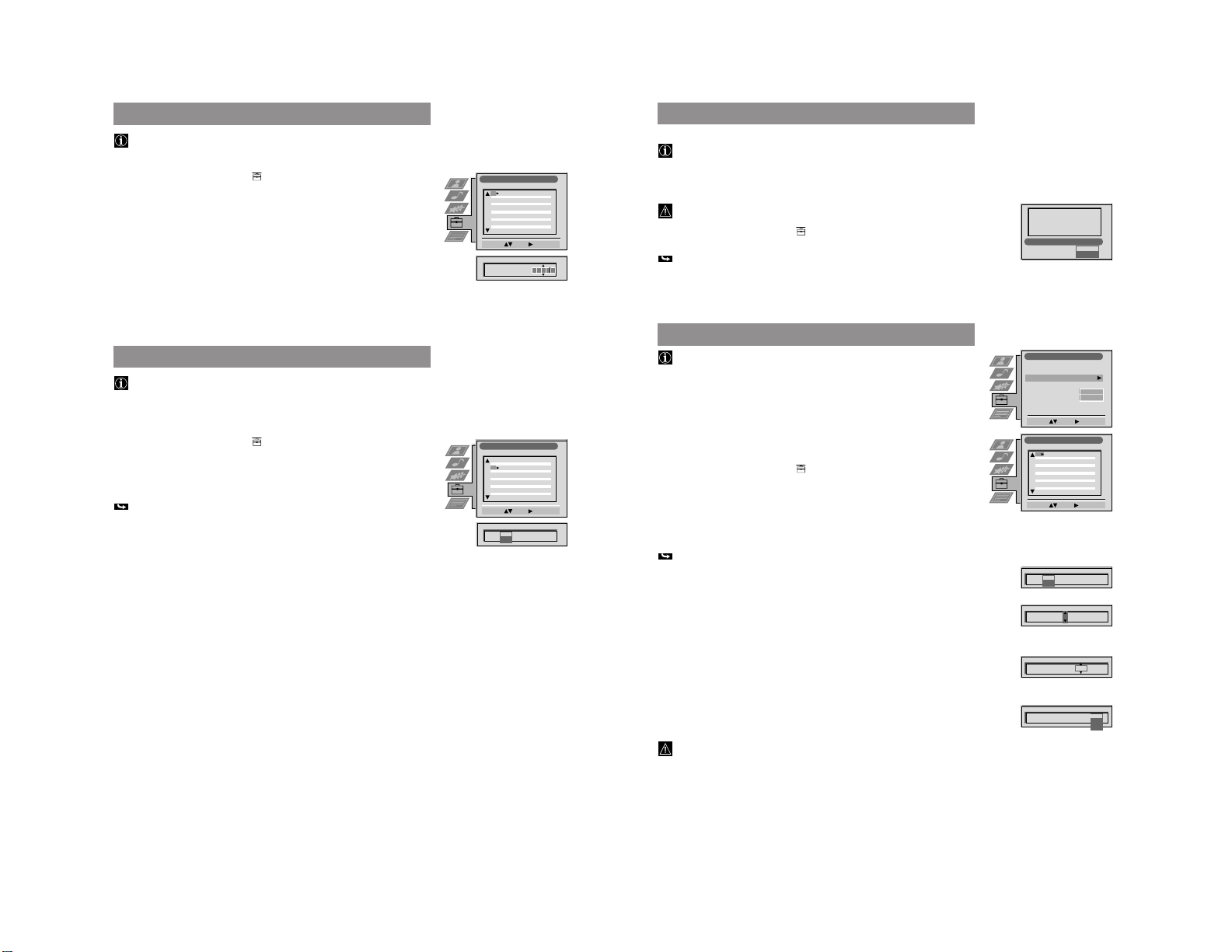
Sorting of Programme Positions
After having used Automatic Tuning of channels you may wish to rearrange
the order of the channels.
1 Press MENU. Select the symbol
using $. Push to ”.
2 Select Programme Sorting using $. Push to ” to enter.
3 Select the programme position of the channel you wish to sort using 4 or $.
Push to ” to enter.
4 Move the channel to the new programme position using 4 or $. Store by
pressing OK.
The channel is now at the new position. The other programme positions
move accordingly.
5 To sort other programme positions repeat steps 3 to 4.
6 Press MENU to return to the normal TV screen.
Manual Tuning In of Channels
Use this function to preset channels or a video input source one by one to
programme positions of your choice.
1 Press MENU. Select the symbol
using $. Push to ”.
2 Select Installation using $. Push to ” to enter.
Select Manual Programme Preset using $. Push to ” to enter.
3 Select the programme position by pushing to 4 or $. Push twice to ”.
The column SYS is highlighted.
4 Select the TV system using 4 or $. Push to ” to enter.
Available TV systems are B/G for western European countries,
D/K for eastern European countries, EXT for a video input source
(please go to step 5c after selecting EXT)
The column CH is highlighted.
5 Select your method for the channel tuning using 4 or $. Push to ” to enter.
You have the choice between C for a terrestrial channel, S for a cable channel,
F for direct frequency input.
a Direct Channel Input - S, C or F
For channel numbers input a two digit number, for the channel frequency a
three digit number.
•
Select the two or three digits by using the number buttons 0 to 9.
•
To start the search and to store the channel, press OK.
•
To preset other channels repeat steps 3 to 5a.
b Channel search (SEARCH)
Use Search if you do not know the channel number or frequency
•
Start the search for the next available channel by pushing to $.
•
Store the channel by pressing OK or continue the search by pushing again to $.
•
To search for other channels repeat steps 3 to 5b.
c For video input sources (EXT)
•
Select the Video Input source using 4 or $.
•
Store your selection by pressing OK.
•
To allocate other sources repeat steps 3 to 5c.
6 Press MENU to return to the normal TV screen.
Programme Sorting
Select Prog.: Confirm:
Set Up
Auto Tuning
Programme Sorting
AV Preset
Installation
Select: Enter:
PROG CH LABEL
Programme Sorting
Select Position: Move: OK
C03 TV 5
PROG CH LABEL
1
2
3
4
5
6
7
8
9
10
11
C03
C05
C07
C08
C09
C11
C12
C13
C14
C15
C16
TV 5
PRO 7
EU-SP
SWF
RTL
SAT
MDR
DDI
DSF
RTL 2
KAB 1
C03
C05
C07
C08
C09
C11
C12
C13
C14
C15
C16
TV 5
PRO 7
EU-SP
SWF
RTL
SAT
MDR
DDI
DSF
RTL 2
KAB 1
1
2
3
4
5
6
7
8
9
10
11
PROG SYS
Off
SKIP LABEL
1 B/G
Installation
Select: Enter:
Language/Country
Manual Programme Preset
Further Programme Preset
RGB Set Up
Picture Rotation
Personal ID
O
- - - - - - -
Manual Programme Preset
Select: Enter:
PROG
CH
SYSSKIP LABEL
C09
C10
ARD
BBC
B/G
B/G
Off
Off
Off
Off
Off
Off
Off
Off
Off
Off
Off
1
2
3
4
5
6
7
8
9
10
11
PROG
Off
SKIP
1
B/G
D/K
EXT
CH
C
S
F
CH
SYS LABEL
PROG
CH
SYS
Off
SKIP LABEL
0 EXT
AV1
AV2
AV3
AV1
PROG SYS
Off
SKIP LABEL
1 B/G
CH
03
SEARCH
12
34
Captioning a Station Name
During presetting the channels are usually labelled automatically.
You can, however, individually name a channel or a video input source.
1 Press MENU. Select the symbol
using $. Push to ”.
2 Select Installation using $. Push to ” to enter.
Select Manual Programme Preset using $. Push to ” to enter.
3 Select the programme position of the channel or the video source you wish to
label by pushing to $ or 4. Push repeatedly to ” until the first element of the
position LABEL is highlighted.
4 Select a number, a letter, + or a blank using 4 or $. Push to ” to confirm.
Select the other four characters in the same way.
5 Store your selection by pressing OK.
6 To label other channels or video sources repeat steps 3 to 5.
7 Press MENU to return to the normal TV screen.
Skipping of Programme Positions
In case of 100 programme positions there may be unused positions, which
you can skip in the menu Manual Programme Preset. When changing
channels with the PROGR +/– buttons they do then not appear.
You can, however, still select them using the number buttons.
1 Press MENU. Select the symbol
using $. Push to ”.
2 Select Installation using $. Push to ” to enter.
Select Manual Programme Preset using $. Push to ” to enter.
3 Select the programme position you wish to skip by pushing to 4 or $.
Push to ” to enter.
The column SKIP is highlighted.
4 Select ON using $.
5 Store by pressing OK.
6 To skip other programme positions repeat steps 3 to 5.
7 Press MENU to return to the normal TV screen.
Advanced Operation
Advanced Presetting
Manual Programme Preset
Select: Enter:
PROG CHSYSSKIP LABEL
C09
C10
ARD
BBC
B/G
B/G
Off
Off
Off
Off
Off
Off
Off
Off
Off
Off
Off
1
2
3
4
5
6
7
8
9
10
11
PROG CHSYS
Off
SKIP LABEL
6 B/G
C07 TE
Manual Programme Preset
Select: Enter:
PROG CHSYSSKIP LABEL
PROG CHSYSSKIP LABEL
53 B/G
F189 - - - Off
On
C09
C10
ARD
BBC
B/G
B/G
Off
Off
Off
Off
Off
Off
Off
Off
Off
Off
Off
51
52
53
54
55
56
57
58
59
60
61
40
Selecting your NexTView Provider*
*depending on availability of service
NexTView is an on-screen electronic programme guide, providing you with
programme information on many broadcasters. Your TV set automatically
selects a NexTView provider. This provider will be available about 30 minutes
after the channel tuning. You can however, also select a provider of your choice.
See Using NexTView on page 48 for information on the operation of NexTView.
When using a satellite receiver make sure to connect the receiver to the aerial
socket of your TV set.
1 Press MENU. Select the symbol
using $. Push z to enter.
2 Select Select NexTView using $. Push z to enter.
A list is displayed containing all available NexTView providers and the
supported broadcasters.
3 Select the desired NexTView provider by using 4 or $. Store by pressing OK.
4 Press MENU to return to the normal TV screen.
Using of Further Programme Preset
Using the menu Further Programme Preset you can
a) individually attenuate the strength of a channel signal in case of a strong
local aerial signal (striped picture).
b) individually adjust the volume level of each channel.
c) improve the quality of a weak channel (picture or sound distortions) with
manual fine tuning.
d) preset the AV output for programme positions of those channels with
scrambled signals (e.g. from a Pay TV decoder). In this way a connected
Smartlink VCR records the unscrambled signal.
1 Press MENU. Select the symbol
using $. Push ” to enter.
2 Select Installation using $. Push ” to enter. Select Further Programme Preset
using $. Push ” to enter.
3 Select the programme position of the desired channel by pushing 4 or $.
Push ” repeatedly to select:
ATT (RF attenuator), VOL (Volume Offset), AFT (Automatic Fine Tuning) or
DECODER.
The selected item changes colour.
4a ATT
Push $ to select ON. Store by pressing OK.
Repeat steps 3 and 4a if you wish to attenuate other channels.
b VOL
Push 4 or $ to adjust the volume level (range -7 to +7) of the channel.
Store by pressing OK.
Repeat steps 3 and 4b if you wish to adjust the volume level of other channels.
c AFT
Push 4 or $ to fine tune the channel (range -15 to +15). Store by pressing OK.
Repeat steps 3 and 4c if you wish to fine tune other channels.
d DECODER
Push to 4 or $ to select AV1 (Euro AV socket 1) or AV2 (Euro AV socket 2) as
output for the video source on this programme position. Store by pressing OK.
Repeat steps 3 and 4d if you wish to preset the AV output of other video sources.
Should you use Auto Tuning afterwards, this setting will
be cancelled.
5 Press MENU to return to the normal TV screen.
Advanced Operation
Advanced Presetting
Select Next View
EURON
VOX
DRS 3SAT ARTE
Channels:
Swiss Text
Euro News
Installation
Select: Enter:
Language/Country
Manual Programme Preset
Further Programme Preset
RGB Set Up
Picture Rotation
Personal ID
Demo
O
- - - - - - -
Further Programme Preset
Select: Enter:
PROG AFTVOLATT DECODER
On
On
On
Off
Off
Off
0
0
0
Off
Off
Off
1
2
3
4
5
6
7
8
9
10
11
PROG AFTVOLATT DECODER
1
Off
On
PROG AFTVOLATT DECODER
1
On 0
PROG AFTVOLATT DECODER
1 On -5
On
PROG AFTVOLATT DECODER
1 On -5 On
Off
AV1
AV2
13
36
When connecting an RGB source such as a Sony playstation you may need to
readjust the picture geometry.
1 Select the connected RGB source by pressing … repeatedly.
2 Press MENU. Select the symbol
using $. Push to ”.
3 Select Installation using $. Push to ” to enter. Select RGB Set Up using $.
Push to ” to enter.
4 Select H Centre by pushing to ”. Adjust the centre of the picture
(range from -10 to +10) using 4 or $. Store by pressing OK.
5 Select H Size using $. Push to ” to enter. Adjust the horizontal coordinates
(range from -10 to +10) using 4 or $. Store by pressing OK.
6 Press MENU to return to the normal TV screen.
Advanced Presetting
Advanced Operation
Adjusting the Picture Rotation
Because of the earth magnetism the picture might slant. In this case you can
readjust the picture.
1 Press MENU. Select the symbol
using $. Push to ”.
2 Select Installation using $. Push to ” to enter. Select Picture Rotation using $.
Push to ” to enter.
3 Adjust the Picture Rotation (adjusting range -5 to +5) by pushing to 4 or $.
Store by pressing OK.
4 Press MENU to return to the normal TV picture.
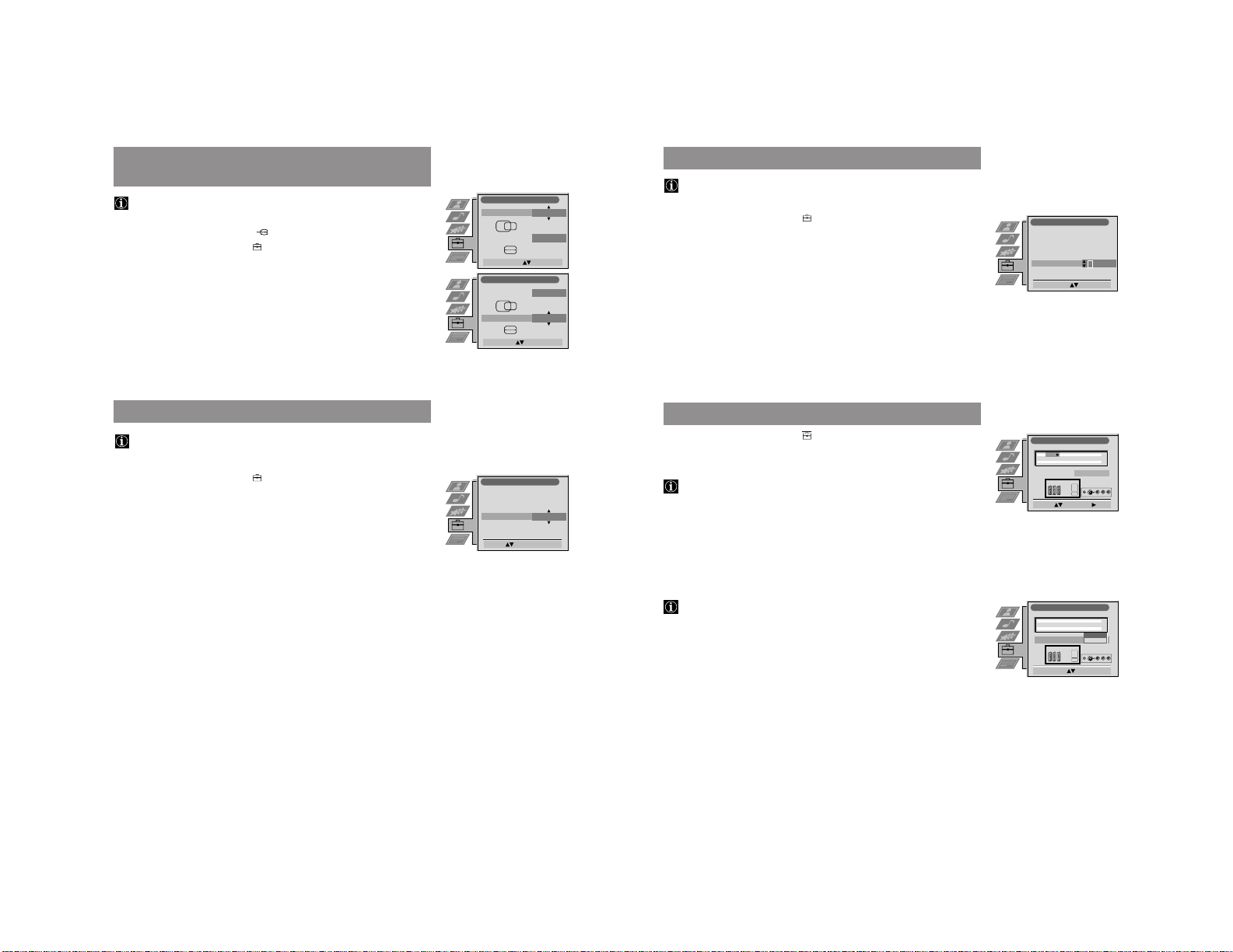
Adjusting the Picture Geometry
for an RGB Source
RGB Set Up
Adjust Size: Confirm: OK
H Centre
O
H Size
O
RGB Set Up
Adjust Position: Confirm: OK
H Centre
O
H Size
O
Installation
Rotate: Confirm: OK
Language/Country
Manual Programme Preset
Further Programme Preset
RGB Set Up
Picture Rotation
Personal ID
O
37
1 Press MENU. Select the symbol
using $. Push to ”.
2 Select AV Preset using $. Push to ” to enter.
3 Select the desired AV input (AV 1, 2 or 3) using 4 or $. Push to ” enter.
After each step you have the choice between memorizing (press OK) or going to
the next item (push to ”).
4 To label the source:
a Push to ” to select Label.
b Select the first character using 4 or $. Push to ” to confirm.
c Repeat step b to select the other 4 characters.
d Store by pressing OK.
5 Repeat steps 3 to 4 for the other AV inputs.
6 Selecting the AV3 Input Source:
In case of AV3 you have the choice between the front AV3 sockets BCor the
rear Scart 3 L connector.
a Push to $ to select AV3 Input. Push to ” to enter.
b Select Front or Rear using 4 or $.
c Store by pressing OK.
7 Press MENU to return to the normal TV screen.
Presetting and Labelling of Input Sources
Advanced Presetting
Inputting Your Personal ID
You can programme your TV with a safety code, so that you can be traced if
your TV is stolen and recovered. This code can only be input once!
Make sure to write it down in this Instruction Manual.
1 Press MENU. Select the symbol
using $. Push to ”.
2 Select Installation using $. Push to ” to enter. Select Personal ID using $.
Push to ” to enter.
3a Select the first of a total of 11 characters (letter, number, + or a blank) by
using 4 or $.
b Push to ” to go to the next character.
c Repeat a and b for all characters.
4 Store by pressing OK.
5 Press MENU to return to the normal TV screen.
Advanced Operation
Installation
Select A-Z, 0-9
: Store: OK
Language/Country
Manual Programme Preset
Further Programme Preset
RGB Set Up
Picture Rotation
Personal ID
- - - - - -
AV Preset
Select: Enter:
AV 3 Input Rear
INPUT LABEL
VIDEO
VIDEO
VIDEO
AV 1
AV 2
AV 3
AV Preset
Select Mode: Confirm: OK
AV 3 Input
INPUT LABEL
VIDEO
VIDEO
VIDEO
AV 1
AV 2
AV 3
Front
Rear
14
44
Advanced TV operation
Picture and sound are adjusted at the factory. You can however, adjust
them individually.
1 Press MENU.
Select the symbol
for Picture or for Sound using 4 or $.
Push to ” to enter.
The menu Picture or Sound Control is displayed.
2 Select the desired item using 4 or $. Push to ” to enter.
3 Adjust the selected item using 4, $, ” and “. Press OK to store.
Refer to the tables on this and the following page for more information.
4 Repeat steps 2 and 3 to adjust other items.
5 Press MENU to return to the normal TV screen.
Picture Control
Item Effect/Operation
Picture Mode $ Live (for live broadcasts)
Personal (for individual settings)
4 Movie (for movie broadcasts)
Contrast Less “” More
Brightness* Darker “” Brighter
Colour* Less “” More
Hue** Reddish “” Greenish
Sharpness* Softer “” Sharper
Reset Resets picture to the factory preset levels
AI 4 Off: normal
(Artificial Intelligence) $ On: Automatic optimization of contrast level
according to the TV signal
Noise Reduction 4 Off: Normal
$ On: Reduces picture noise in case of a weak
broadcasting signal
Digital Mode $ Normal: 100 Hz
Digital+: 100 Hz plus line flicker reduction
4 Advanced: Digital+ plus smoothing of motions
* Only if Personal is selected in Picture Mode
** Only available for NTSC colour signal (e.g. US video tapes)
Sound Control
Item Effect/Operation
Equaliser mode Select between the following sound settings
$ Personal
Vocal
Jazz
Rock
Pop
4 Flat (fixed setting, cannot be adjusted)
Adjusting Picture and Sound
Advanced Operation
Picture Adjustment
Select Mode: Enter:
Picture Mode
Contrast
Brightness
Color
Sharpness
Reset
AI
Noise Reduction
Digital Mode
Personal
On
On
Normal
Picture Mode
Live
Personal
Movie
Contrast
AI
On
Off
Noise Reduction
On
Off
Digital Mode
Normal
Digital+
Advanced
Audio Adjustment
Equaliser Mode
Equaliser
Adjustment
Surround Mode
SRS Mode
Auto Vol. Control
Dual Sound
Volume
Dual Sound
Personal
Mono
Off
SRS 2
SRS
Mono
Personal
Vocal
Jazz
Rock
Pop
Flat
Select Mode: Confirm: OK
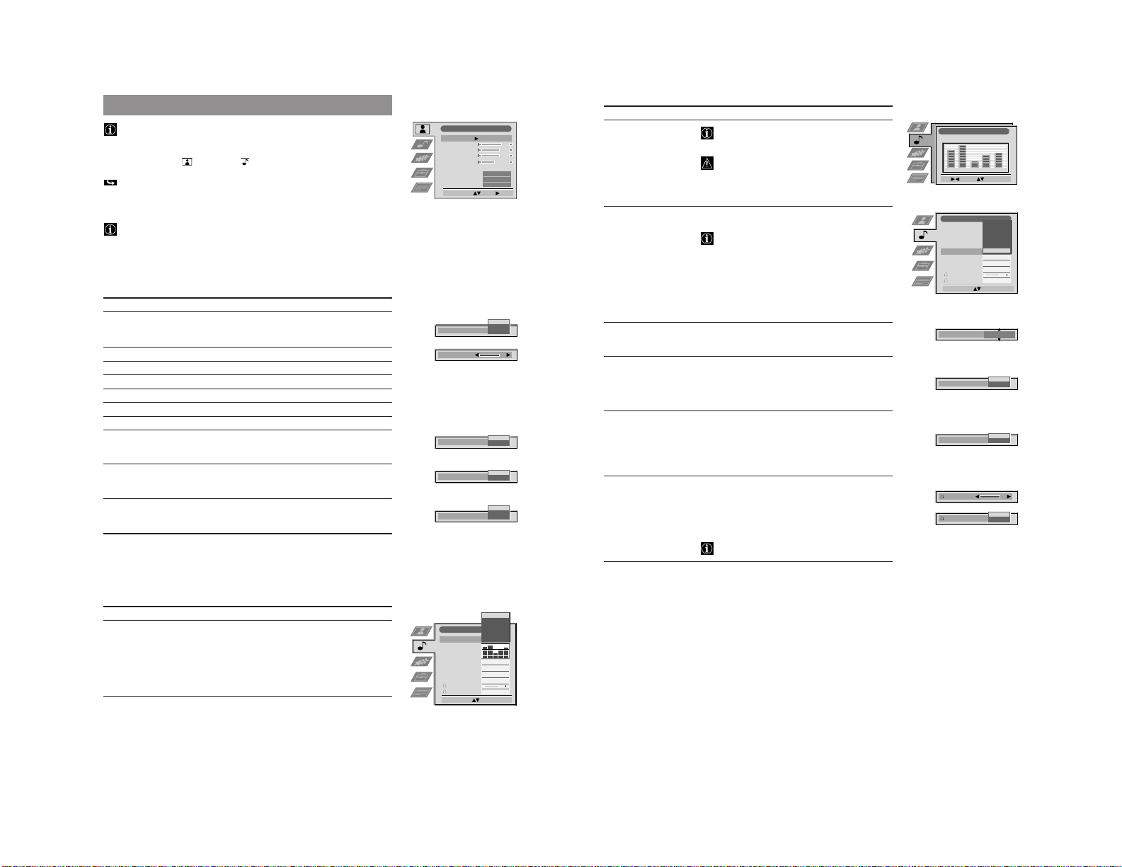
45
Sound Control (continued)
Item Effect/Operation
Equaliser adjustment
You can adjust the mode selected in Equaliser
mode by cutting and boosting of 5 selected
frequency bands.
Only the changes made in Personal can be stored,
the others return to factory setting.
•
Select the desired bar using ” or “, adjust using 4
and $.
Press OK to store.
Surround mode 4 Off: Normal
Dolby Sur. (Pro Logic or Tru Surround **)
Select when receiving a Dolby broadcast.
After the broadcast return to off, otherwise the
TV automatically selects Dolby for any stereo
broadcast and the sound will be distorted.
SRS
Hall
Church
Disco
$ Stadium
SRS-Mode* 4 SRS 1
*only when SRS is selected SRS 2
in Surround mode $ SRS 3
Auto Volume Control 4 On: volume level of the channels will stay the same
independent of the broadcast signal
(e.g. in case of advertisements)
$ Off: volume level changes according to the
broadcast signal
Dual Sound For a bilingual broadcast:
$ A for channel 1
4 B for channel 2
For a stereo broadcast:
$ Mono
4 Stereo
Headphones
2 Volume Less “ ” More
2 Dual Sound For a bilingual broadcast:
$ A for channel 1
4 B for channel 2
PAP
When PAP is switched on, you can additionally
select the PAP sound for the headphones
** TruSurround is a trademark of SRS Labs, Inc. SRS and the SRS symbol are
registered trademarks of SRS Labs, Inc. in the Unites States and selected foreign
countries. SRS and TruSurround are incorporated under license from SRS Labs, Inc.
and is protected under United States Patent Nos. 4,748,669 and 4,841,572 with
numerous additional issued and pending foreign patents. Purchase of this product
does not convey the right to sell recordings made with the TruSurround technology.
Advanced TV operation
Advanced Operation
Equaliser Adjustment
Sel: Adjust: Confirm:OK
Personal
+
0
–
120 150 1,5K 5 K 10 K
SRS 2
SRS Mode
Auto Vol. Control
Off
On
Dual Sound
Mono
Stereo
Volume
Dual Sound
A
B
Audio Adjustment
Personal
Mono
Off
SRS 2
SRS
Mono
Stadium
Disco
Church
Hall
SRS
Dolby Sur.
Off
Select Mode: Confirm: OK
Equaliser Mode
Equaliser
Adjustment
Surround Mode
SRS Mode
Auto Vol. Control
Dual Sound
Volume
Dual Sound

15
46
Using the Features Menu
1 Press MENU. Select the symbol using $. Push z to enter.
2 Select the desired menu item using $. Push z to enter.
3 Select the desired setting using 4 or $.
4 Store by pressing OK.
5 Press MENU to return to the normal TV screen.
Using Multi PIP
Multi PIP (picture in picture) mode displays a succession of 12 still pictures
and a 13th that is live. You can manually select which channel you wish to
watch, either full-screen or in the PIP mode.
1 Press
.
Now 13 programme positions appear on the screen, with the current channel in
the centre.
2 Press PROGR +/- repeatedly to get the next or the preceding 12 programme
positions .
3 Use 4, $, “ and ” to move within the 13 displayed channels.
Press OK to select the framed channel.
The selected channel moves to the centre.
4 When the centre channel is framed, press OK to get the channel full screen or
press
to return to the normal TV mode.
Advanced Operation
Advanced TV operation
Features
Item Effect/Operation
Auto Format* 4 On: Automatic selection of the screen format
*only for aerial signal $ Off: Normal mode
Format Correction* 4 On: Smart mode is selected automatically for 4:3/
*only if Auto Format is on 14:9 broadcasts
$ Off: 4:3/14:9 is selected
Sleep Timer
You can select a time period after which the TV
switches itself into standby mode
4 Off
10 min.
20 min.
.
.
.
$ 90 min.
Parental Lock $ Off: Normal mode
4 On: TV can only be switched on out of
standby-mode using the Remote Commander,
the buttons on the TV do not work.
AV2 Source
You can select the source to be output from the
Scart connector
Y
2/
j
2. In this way you can
record from this socket while watching another
source.
4 TV audio/video signal from the aerial ˘
AV1 audio/video signal from Scart 1
AV2 audio/video signal from Scart 2
$ AV3 audio/video signal from front or rear connectors
Features
Auto Format
Format Correction
Sleep Timer
Parental Lock
AV 2 Source
On
On
Off
Off
TV
Select: Enter:
Auto Format
Off
On
Format Correction
Off
On
10 min
Sleep Timer
Parental Look
Off
On
AV 2 Source
AV 3
AV 2
AV 1
TV
03 05
01 06
11 09 08
02
10
07
13
12
04
47
Using Screen Mode
When Auto Format in the Features menu is preset to »On« and a format signal
is being transmitted, the TV set automatically selects the detected screen format.
Screen mode, however, lets you select the screen format of your choice.
•
Press 9 repeatedly to get one of the following formats:
Smart imitation of wide screen effect for 4:3 broadcasts, parts of the top and
bottom of the picture are cut off
4:3 conventional 4:3 aspect ratio, full picture information
14:9 compromise between 4:3 and 16:9 aspect ratios
Zoom imitation of wide screen effect for letterboxed movies
Wide for 16:9 broadcasts
In Zoom and 14:9 modes parts of the top and the bottom of the screen are cut
off. Using 4 and $ you can adjust the position of the image onscreen to e.g.
read subtitles. Press OK to confirm.
Advanced TV operation
Advanced Operation
Operating PAP (Picture and Picture)
PAP divides the screen into two for watching two channels simultaneously
(with a video source on one if you want).
The sound of the left screen is on the TV loudspeakers, the sound of the right
screen is selectable via headphones.
Switching PAP on and off
•
Press
´/´
6 once to display the screens in format 4:3 and twice to switch
PAP off.
Selecting a PAP source
1 Press > 5.
The symbol > appears in the right screen.
2 Select the desired source using the number buttons (for a TV channel) 7 or
…3 (for a video source).
Swapping screens
•
Press
Å/a
4 to swap the two screens.
Zooming the screens
•
Using the joystick buttons “ and ” you can change the size of the two screens.
When you press ” repeatedly the right screen gets bigger, while the left screen
gets smaller.
Smart
Zoom
Wide
16
50
Teletext
Most TV channels broadcast information via teletext. The index page of the teletext
service (usually page 100) gives you information on how to use the service.
Make sure to use a TV channel with a strong signal, otherwise there may be
Teletext errors.
Direct Access Functions
Switching Teletext on and off
1 Select the TV channel which carries the teletext service you want to view.
2a Press f @º once for Picture and Teletext (P&T).
The screen is divided in two, with the TV channel in the right corner and the
Teletext display on the left.
P&T mode: Press
Å/a
4. Press PROGR +/- !£ to change the channel of the
TV screen. Push “ or ” to change the size of the TV screen.
Press
Å/a
4 again to resume normal teletext reception.
b Press f twice to get Teletext only.
c Press f three times for Mix mode.
The TV broadcast and the Teletext display are overlapped.
3 Press
;
@¡ or press f a fourth time to switch teletext off.
Selecting a Teletext Page
Direct Page Selection
•
Input the three digits of the page number using the number buttons 7.
If you have made a mistake:
Type in any three digits, then re-enter the correct page number.
Page Catching
1 Select a teletext page which has several page numbers on it (e.g., the index
page).
2 Press OK !¡.
Page Catching is displayed.
3 Select the desired page number using 4 or $ !¡ and press OK.
The requested page is displayed after some seconds.
Selecting the next or the preceding page
•
Press !£ (Page +) or (Page -).
Selecting the index page
•
Press
+
2.
Selecting a subpage
A teletext page may consist of several subpages. In this case an information line
is displayed, showing the number of subpages.
•
Select the mode by pushing 4. Select the subpage by using 4 or $.
Freezing a Teletext subpage
1 Press !• or R 3
The symbol R is displayed and the subpage is not updated.
2 Press f @º to resume normal teletext reception.
Using Fastext*
*depending on availability of service
Fastext lets you access pages with one button stroke. When Fastext is broadcast,
a colour-coded menu appears at the bottom of the screen. The colours of this
menu correspond to the red, green, yellow and blue buttons 9, !º, !∞, !§ on
the Remote Control.
•
Press the coloured button which corresponds to the colour in the
colour-coded menu.
Advanced Operation
01
100
Teletext TV
216-02
01 03 04 05 06 07 0802
51
Using the Teletext Menu
This TV set has a menu-guided teletext system. When teletext is switched on
you can use the joystick buttons to operate the teletext menu.
Select the menu functions as follows:
1 Press MENU !™.
The Teletext menu is superimposed onto the teletext display.
2 Select the teletext function using 4 or $ !¡. Push ” to enter.
Top/Bottom/Full
For convenient reading of a Teletext page you can enlarge it.
After having selected the function, a sub menu Top 4 Bottom $ Full OK is
displayed.
•
Push 4 to enlarge the upper half of the screen, push $ to enlarge the lower
half. Press OK to resume the normal size.
Press f to resume the normal Teletext operation.
Text Clear
After having selected the function, you can watch a TV channel while waiting
for a requested Teletext page. As soon as the page is available, the symbol f
changes colour.
•
Press f to view the page.
Reveal
Some teletext pages contain hidden information (e.g., for a quiz), which you can
reveal.
After having selected the function, the hidden information appears.
•
Press f to resume the normal Teletext operation.
Time Page*
*depending on availability of service
You can call up a time-coded page - such as an alarm page - at a time specified
by you.
After having selected the function a sub menu is displayed.
1 Select On using 4 or $. Push ” to enter.
2 Enter the three digits of the desired page using the number buttons 7.
3 Enter the four digits of the desired time using the number buttons 7.
4 Press OK to store.
The time is displayed in the top left-handed corner of the screen.
At the requested time the page is displayed.
Teletext
Advanced Operation
Teletext
Top / Bottom / Full
Text Clear
Reveal
Time Page
Select: Enter Menu:
Top: Bottom: Full: OK
Time Page
PAGE TIME
Select: Enter:
– – – - - : - -
17
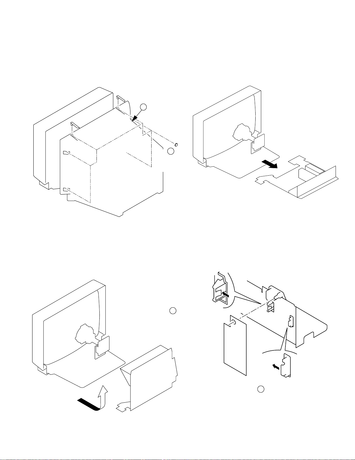
2-1. REAR COVER REMOVAL
2-3. SERVICE POSITION
2-2. CHASSIS ASSY REMOVAL
1
6 Screws
BTV 4x16
2 Rear Cover
2-4. U BOARD REMOVAL
2 Pull the Board in
the direction of the
arrow and remove.
SECTION 2
DISASSEMBLY
CAUTION:
Take care not to damage the C Board when removing
or refitting the rear cover.
1 Push the
claw in the
direction of the
arrow and
remove.
18
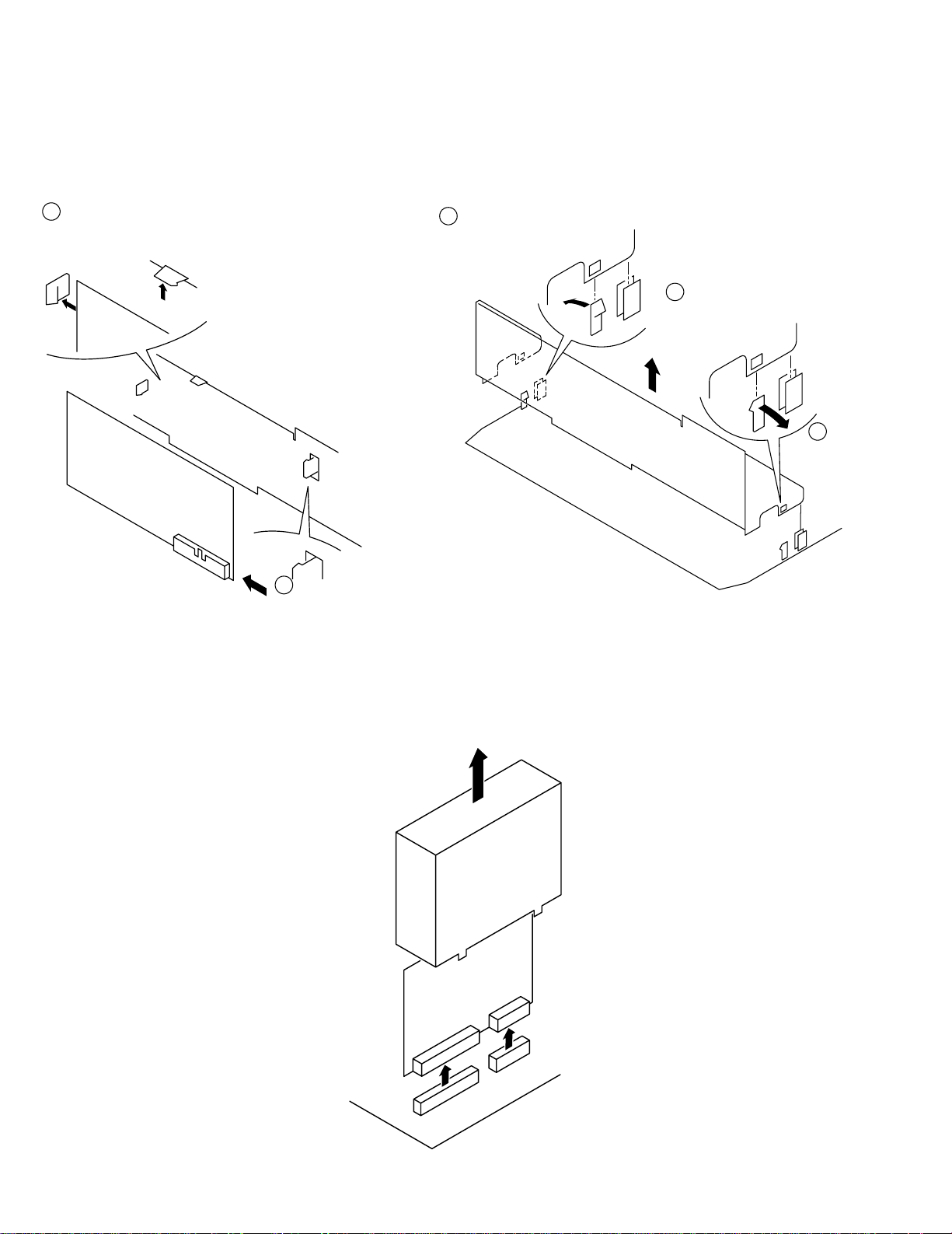
2-5. J BOARD REMOVAL
2-7. B1 BOARD REMOVAL
2-6. J SHIELD REMOVAL
1 Push the claw in
the direction of the
arrow and remove.
2 Pull the Board in
the direction of the
arrow and remove.
1 Push the claw in
the direction of the
arrow and remove.
2 Push the
claw in the
direction of
the arrow
and remove.
3 Remove the shield in
the direction of the arrow.
All other boards are removed in a
similar manner to those shown
NOTE
19
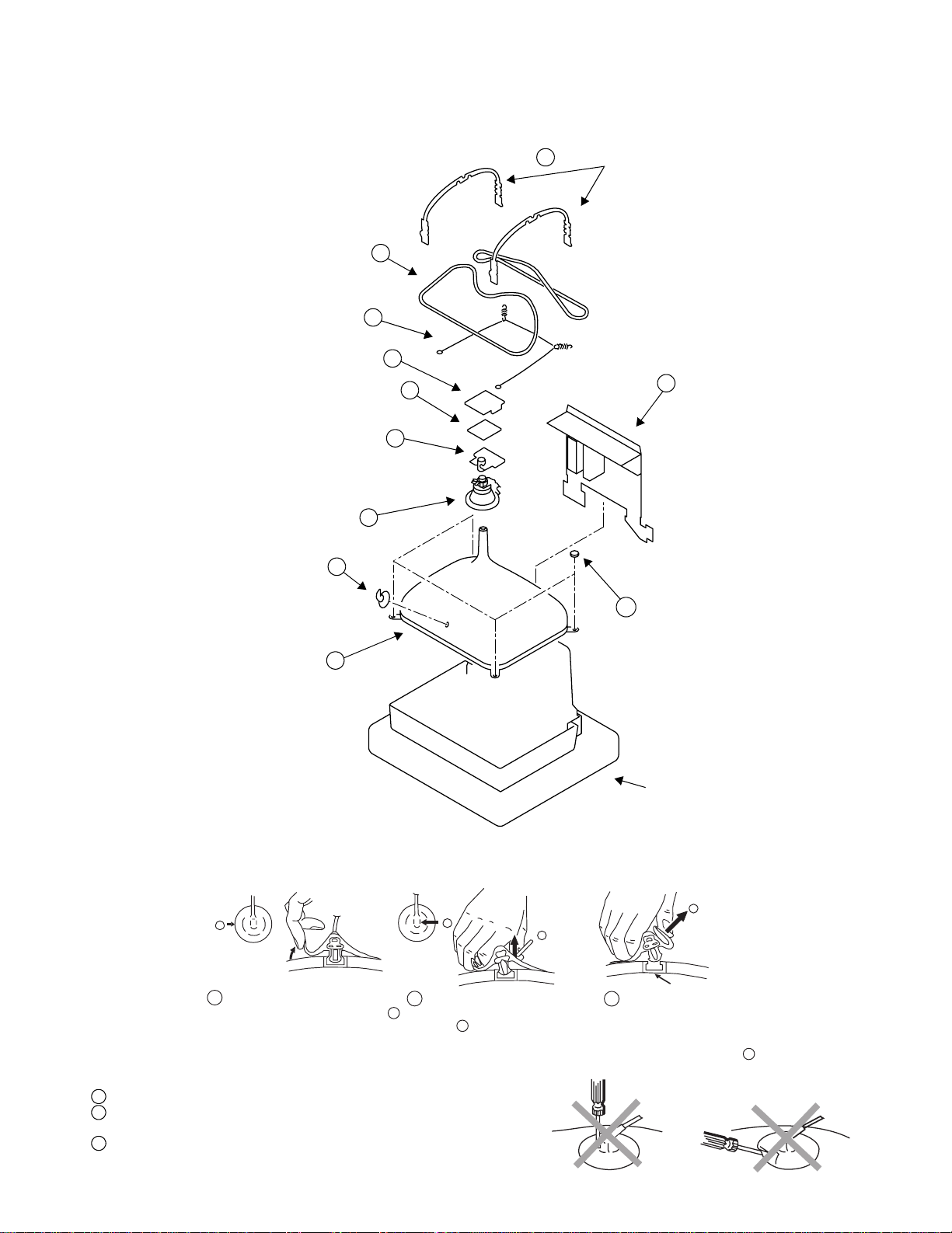
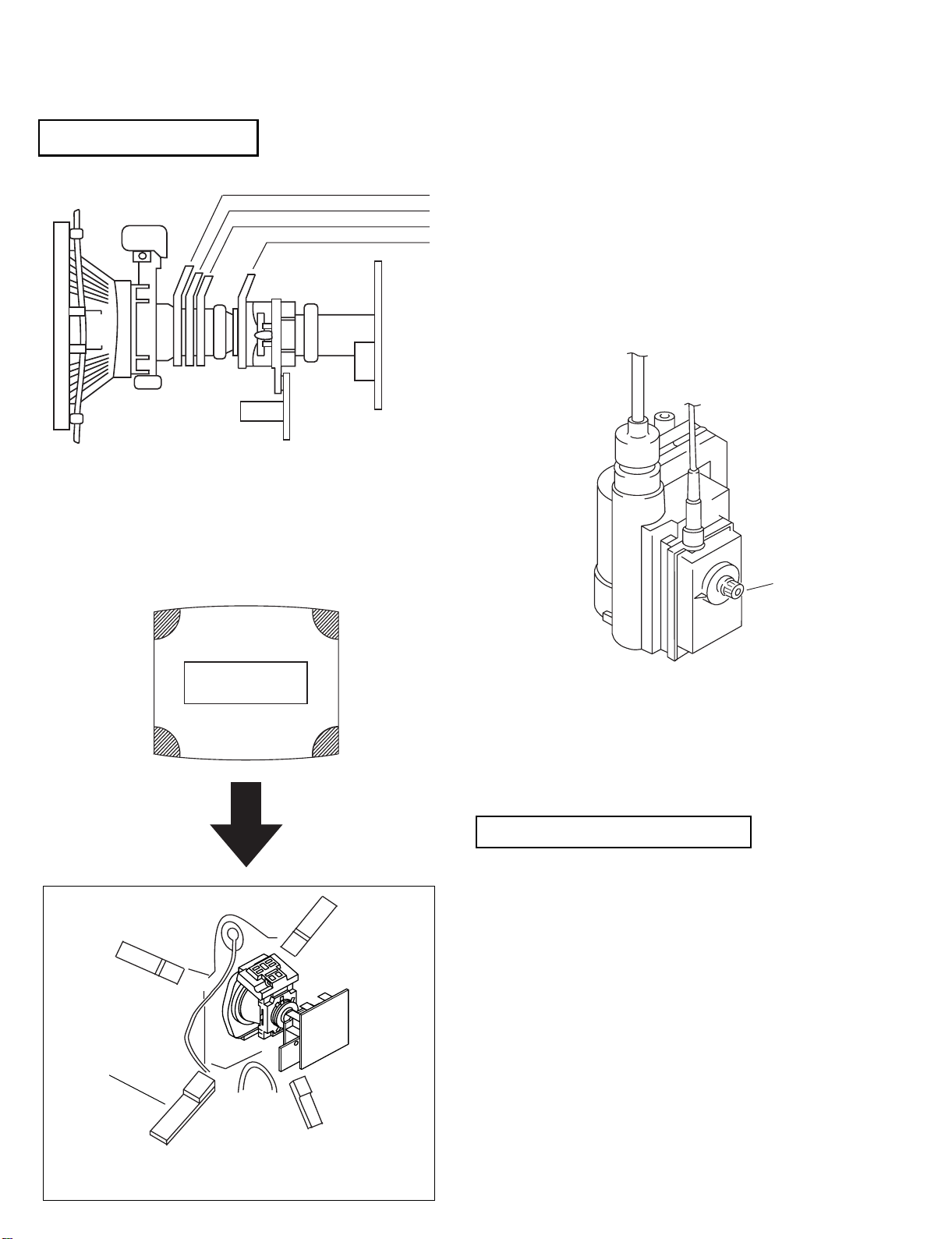
Anode button
a
* REMOVING PROCEDURES.
Turn up one side of the rubber cap in
the direction indicated by the arrow a
1
2 Using a thumb pull up the rubber cap
firmly in the direction indicated by the
arrow b
3 When one side of the rubber cap is
separated from the anode button, the
anode-cap can be removed by turning
up the rubber cap and pulling it up in
the direction of the arrow c
b
b
c
Note : Short circuit the anode of the picture tube and the anode cap to the metal chassis, CRT shield or carbon paint on the CRT, after removing the anode.
• REMOVAL OF ANODE-CAP
• HOW TO HANDLE THE ANODE-CAP
1 To prevent damaging the surface of the anode-cap do not use sharp materials.
2 Do not apply too great a pressure on the rubber, as this may cause damage to
the anode connector.
3 A metal fitting called a shatter hook terminal is fitted inside the rubber cap.
Do not turn the rubber foot over excessively this may cause dam age if the
shatter hook sticks out.
Cushion
7 DGC holder
Picture tube 11
C board 3
Spring tension 9
Degaussing coils 8
Anode cap 1
Neck assy 5
VM board 4
Deflection yolk 6
2 Chassis assy
10 Four PT screws
2-8. PICTURE TUBE REMOVAL
20
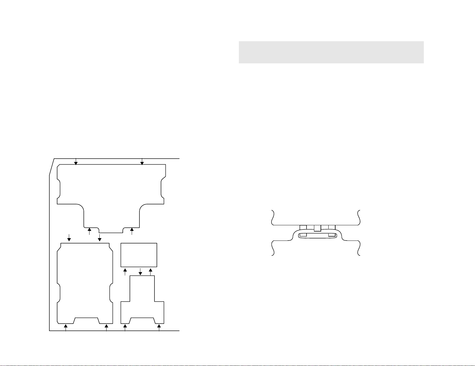
REMOVAL AND REPLACEMENT OF THE MAIN-BRACKET
BOTTOM PLATES.
(1) REMOVING THE PLATES
In the event of servicing being required to the solder side of the D Board printed
wiring board, the bottom plates fitted to the main chassis bracket require to be
removed.
This is performed by cutting the gates with a sharp wire cutter at the locations
indicated by arrows.
Note :There are 4 plates fitted to the main bracket and secured by 4 gates.
Only remove the necessary plate to gain access to the printed wiring board.
(2) REFITTING THE PLATES
Because the plates differ in size it is important that the correct plates are refitted in
their original location.
Please note that the plates need to be rotated 180 degrees from the cut position to
allow the tabs to be fitted in the catch positions.
£
For safety reasons, on no account should the plates be
removed and not refitted after servicing.
Tab
Catch
21
• When complete readjustment is necessary or a new
picture tube is installed, carry out the following
adjustments.
• Unless there are specific instructions to the contrary,
carry out these adjustments with the rated power supply.
• Unless there are specific instructions to the contrary, set the
controls and switches to the following settings:
Contrast ............... normal
Brightness ............... normal
Carry out the following adjustments in this order:
3-1. Beam Landing
3-2. Convergence
3-3. Focus
3-4. White balance
Note: Test equipment required
1. Color bar/pattern generator.
2. Degausser.
3. Digital multimeter.
4. Oscilloscope.
SECTION 3
SET-UP ADJUSTMENTS
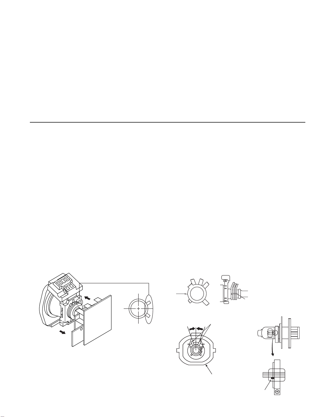
3-1.BEAM LANDING
Preparation:
1. In order to reduce the influence of geomagnetism on the set’s
picture tube, face it in an easterly or westerly direction.
2. Switch on the set’s power and degauss with the
degausser.
(1) Adjustment of Correction Magnet for Y-Splitting
Axis
1. Input a crosshatch signal from the pattern generator.
2. Set the Picture control to minimum and confirm that the
Brightness control is set to normal.
3. Position the neck assembly as indicated in Fig.3-2.
4. Move the deflection yolk as far forward as is possible.
5. Adjust the upper and lower pin symmetrically by opening or
closing the Y-splitting axis correction magnets located on the
neck assembly.
6. Return the deflection yolk to its original position.
Caution :
High voltages are present on the Deflection yolk terminals - take care
when handling the Deflection yolk whilst carrying out adjustments.
(2) Landing
Note :Before carrying out the following adjustments
adjust the magnets as indicated below [See Fig.3-3].
1. Input an all-white signal from the pattern generator.
Maximize the picture setting and adjust the Brightness
setting.
2. Rough-adjust the focus and horizontal convergence.
3. Loosen the deflection yolk screws and align the purity
adjustment knob to its central position. [See Fig.3-1].
4. Switch from the all-white pattern to an all-green pattern.
5. Move the deflection yolk backwards and adjust with the
purity magnet so that the green is at the centre and it aligns
symmetrically. [See Fig.3-4].
6. Move the deflection yolk forward and adjust so that the
entire screen becomes green.
7. Switch the raster signal to red, then to blue and verify the
landing condition.
8. When the position of the deflection yolk has been determined,
fasten the deflection yolk with the screw.
9. If the beam does not land correctly in all the corners of the
screen, use magnets to correct it. [See Fig.3-5].
Y-splitting axis correction magnet
Fig.3-1
Fig.3-2
Purity
Align Pips
on each
magnet
Neck assy
Align the bottom edge
of the neck assy with
the G3 hole centre.
Deflection yoke
Fig.3-3
22
(Open)
(Close)
B
G
R
B
G
R
B
GR
Fig.3-4
Fig. 3-5
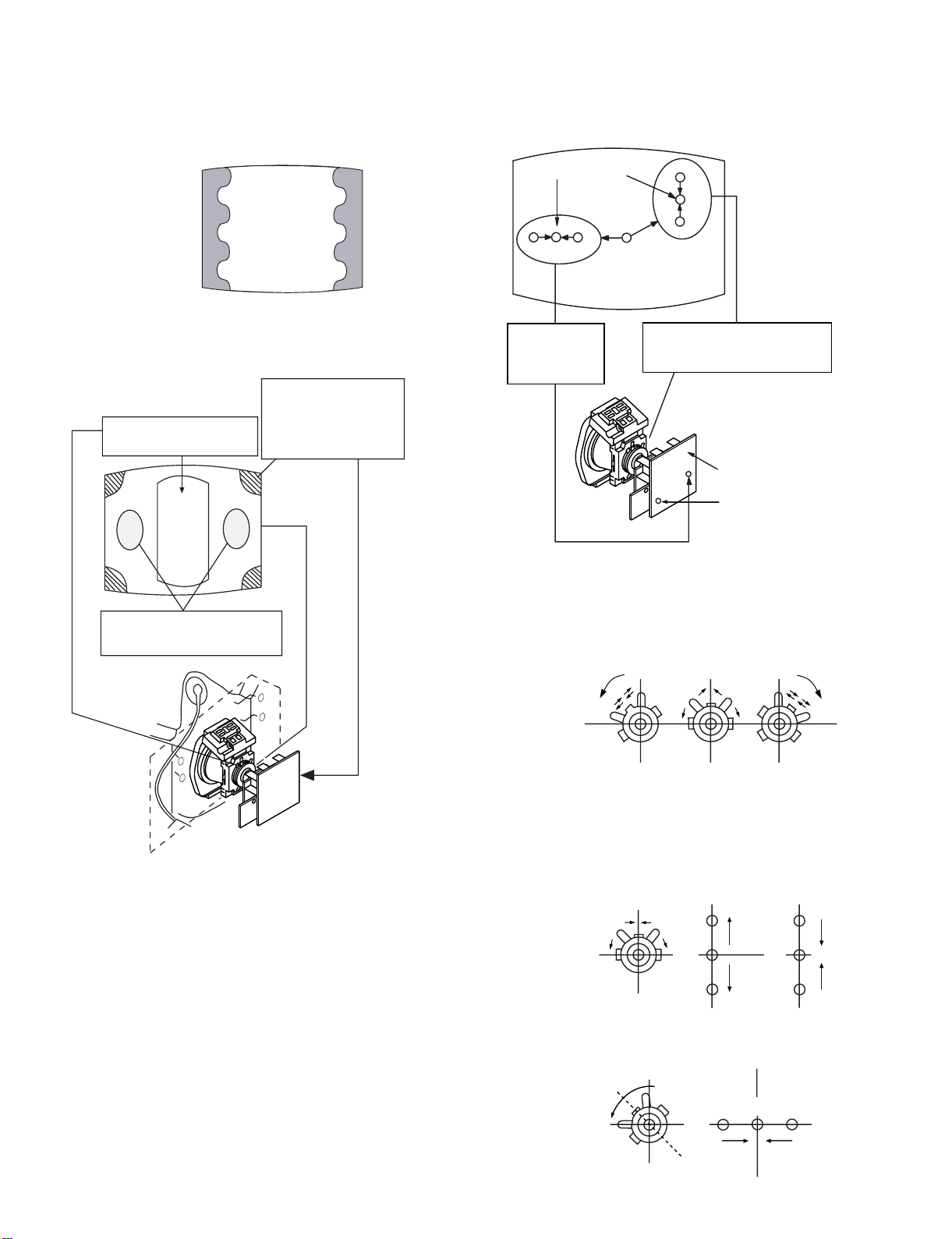
3-2.CONVERGENCE
(1) Screen centre convergence
[Static convergence]
1. Input a dot signal from the pattern generator.
Normalize the picture setting.
2. [Moving horizontally], adjust the H.STAT control so that the
horizontal red, green and blue dots coincide at the centre of the
screen.
3. [Moving vertically], adjust the V.STAT magnet so that the
vertical red, green and blue dots coincide at the centre of the
screen.
• If the horizontal dots are unable to coincide with the variable
range of the H.STAT convergence, adjust together with the
V.ST AT convergence while tracking.
[Adjust the convergence by tilting the V.STAT convergence or
by opening and closing the V.STAT convergence.]
4. Movement of the red, green and blue dots by tilting the
V.STAT magnet and by opening or closing the V.STAT
magnet.
a). By opening or closing the V.STAT magnet, the red, green and
blue dots move as indicated
below.
b). By rotating the V.STAT magnet counter
clockwise, the red,
green and blue
dots move as
indicated
below.
Purity control corrects
this area.
Disk magnets or
rotatable disk
magnets correct
these areas (a-d).
Deflection yoke positioning
corrects these areas
H.STAT
convergence
control
V.S TAT
vertical static magnet
Center dot
H.STAT VR on
mount side
RV5376
Screen (G2)
H.STAT convergence
GREEN
BLUE
RED
23
B
GR
B
G
R
B
G
R
HMC correction(A) HMC correction(B)
A < B
A = B
RG B
RG B
A > B
A = B
RGB
RG B
C < D
C = D C > D C = D
R
G
B
C
D
C
D
R
G
B
R
G
B
R
G
B
VMC correction(A) VMC correction(B)
c). By ro tating the V.STAT magnet clockwise, the red, green and
blue dots move in the direction indicated below.
d). By opening or closing the V.STAT magnet, the red, green and
blue dots move in the direction indicated below.
Note : If the blue dot does not coincide with the red and
green points correct the points by using the BMC
[Hexapole] magnet.
5. Correction for HMC [horizontal mis-convergence] and
VMC [vertical mis-convergence] by using the BMC
[Hexapole] magnet.
a). HMC correction by BMC [Hexapole] magnet and movement
of the electron beam.
b). VMC correction by BMC [Hexapole] magnet and movement
of the electron beam.
HAMP
7. HTIL correction can be performed by adding a THL correction
ASSY to the DY.
HTIL
TLH correction Assy
4-057-714-01
24
FOCUS
Layout of each control
Fig 3-5
Note : If you are unable to adjust the corner convergence
properly, this can be corrected with the use of
permalloys.
3-3.FOCUS
1. Receive a television broadcast signal.
2. Normalize the picture setting.
3. Adjust the focus control located on the flyback transformer to
obtain the best focus at the centre of the screen.
Bring only the centre area of the screen into focus, the
magenta-ring appears on the screen. In this case, adjust the
focus to optimize the screen uniformly.
3-4.SCREEN (G2), WHITE BALANCE
[Adjustment in the service mode using the remote
commander]
G2 adjustment (RV5376)
1. Input a dot signal from the pattern generator.
2. Set the Picture, Brightness and Colour to minimum.
3. Appl y 175V DC from an external power supply to the
R, G and B cathodes of the CRT.
4. Whilst watching the picture, adjust the G2 control
RV5376 [SCREEN] located on the C Board to the point
just before the flyback return lines disappear.
Y-splitting axis correction magnet
V STAT convergence magnet
BMC (Hexaploe) magnet
Purity magnet
a-d: screen-corner
convergence defect
a
b
c
d
Convergence adjustment with permalloy
Permalloy Assy
X-4387-214-1

25
White balance adjustment for TV mode
1. Inpu t an all-white signal.
2. Enter into the Service Mode by pressing ‘TEST’, ‘TEST’ and
‘MENU’ ‘MENU’on the Service Commander.
3. Select ‘Backend’ from the on screen menu
display and press ‘OK’.
4. The ‘Backend’ menu will appear on the screen.
5. Set the contrast to MAX.
6. Set the ‘R DRIVE’ to 41.
7. Adjust the ‘G DRIVE’ and ‘B DRIVE’ so that the white
balance becomes optimum.
8. Press the ‘OK’ button to write the data for each item.
9. Set the contrast to MIN.
10. Set the ‘R CUT-OFF’ to 31.
11. Adjust the ‘G CUT-OFF’, and ‘B CUT-OFF’ with the left and
right buttons on the remote commander so that the white balance
becomes optimum.
12. Press the ‘OK’ button to write the data for each item.
Backend
No D escr. Def Min Max Data
1R-on ONOFFON ON
2G-on ONOFFON ON
3 B-on ON OFF ON ON
4 D-col OFF OFF ON ON
5Color-axis 2032
6Contrast 6306363
7Limit-Luv 3033
8Hue 3106331
9Colour 3106328
10CTI -Level 2032
11 Brightness 31 0 63 31
12Gamma 2032
13 Sharpness 31 0 63 44
14LTI-Level 0030
15 R-Drive 41 0 63 40
16 BLK-Bottom 0030
17G-Drive 41063 38
18ABL-TH 0030
19 B-Drive 41 0 63 21
20ABL-Mode 2032
21 Sub Bright 31 0 63 32
22VM-Level 2032
23 R-Cutoff 31 0 63 41
24Preover 2032
25 G-Cutoff 31 0 63 45
26DPIC-Level 2032
27 B-Cutoff 31 0 63 48
28DC-Tran 1031
29 Sub-Cont 7 0 15 7
30 LRGB2-Lvl 12 0 15 12
31 P-Abl 15 0 15 15
32 DL-Pass OFF OFF ON OFF
33 Sharp.Fo ON OFF ON ON
34 Aging-W OFF OFF ON OFF
35 Aging-B OFF OFF ON OFF
36 CB-offset1 7 0 15 7
37 CR-offset1 7 0 15 7
38 CB-offset2 7 0 15 7
39 CR-offset2 7 0 15 7
40 Sub Colour 0 -8 8 -1
26
SECTION 4
CIRCUIT ADJUSTMENTS
4-1.ELECTRICAL ADJUSTMENTS
Service adjustments to this model can be performed using the supplied Remote Commander RM-891.
HOW TO ENTER INTO SERVICE MODE
1. Turn on the main power switch of the set while pressing PROG + (plus) and PROG - (minus) buttons on the top panel.
2. "TT" will appear in the upper right corner of the screen.
3. Press the ‘MENU’ button twice on the remote commander to obtain the service menu on the screen.
4. Push the joystick up or down on the remote commander to select the adjustment item.
5. Push the right button to proceed to the next menu.
6. If the required adjustment item is ‘Deflection’, push the down button to move to ‘Deflection’.
7. Push the joystick to the right to enter into ‘Deflection’.
8. Change the data in order to comply with each standard.
NOTE:
• Before performing any adjustments assure that the correct model has been selected in the Model Setting menu.
• After carrying out the service adjustments, to prevent the customer accessing the Service Menu switch the TV set OFF and then ON.
+
–
+
–
PROGR
CONTROL
SERVICE MENU
Initialising
Reset Devices
Monitoring
Backend
Deflection
Dynamic Convergence
Colour Decoder 1
Colour Decoder 2
Feature Low - End
PIP
Special Adjustment
Select :
Backend
Deflection
Dynamic Convergence
Colour Decoder 1
Colour Decoder 2
Feature Box
PIP
Sound
RESET DEVICES
INITIALISING
Model Setting
Basic Setting
Feature Setting
Device Status monitor
Error Monitor
Production Monitor
NVM Monitor
Line 23 Monitor
MONITORING
Next Menu

27
Fig.4-1
Model Setting
1 KV-29FX60A/D/E
2KV-29FX60B
3KV-29FX60U
4 KV-29FC60A/D/E
5 KV-29FC60B
6 KV-29FC60K
7 KV-29FC60R
8 KV-29FS60A/D/E
9KV-29FS60B
10 KV-29FS60K
11 KV-29FS60R
12 KV-28/32FX60A/D/E
13 KV-28/32FX60B
14 KV-28/32FX60K
15 KV-28/32FX60R
16 KV-28/32FX60U
17 KV-29FS60A/D/E
18 KV-29FS60B
Fig.4-2
Basic setting
No Descr. Min Max Data
1 Sys.B/G OFF ON ON
2 Sys.D/K OFF ON ON
3Sys.L OFFON ON
4 Sys I (UK) OFF ON OFF
5 Sys I (IRL) OFF ON OFF
6 Russian sound OFF ON OFF
7 TXT Nod.option 1 4 3
8 si mple PAT OFF ON OFF
9 16:9 CRT OFF ON OFF
10 Sub-woofer OFF ON ON
11 Auto stand-by OFF ON ON
12 comb-filter OFF ON OFF
13 Auto YC det OFF ON ON
14 Auto comb det OFF ON OFF
15 AV2 Available OFF ON ON
16 AV3 Available OFF ON ON
17 AV4 Available OFF ON OFF
18 AV3 Front & rear OFF ON ON
19 SECAM Tape OFF ON OFF
Fig.4-3
Backend
No D esc r. D ef Min Max Data
1R-on ONOFFON ON
2G-on ONOFFON ON
3 B-on ON OFF ON ON
4 D-col OFF OFF ON ON
5Color-axis 2032
6Contrast 6306363
7Limit-Luv 3033
8Hue 3106331
9Colour 3106328
10CTI -Level 2032
11 Brightness 31 0 63 31
12Gamma 2032
13 Sharpness 31 0 63 44
14LTI-Level 0030
15 R-Drive 41 0 63 40
16 BLK-Bottom 0030
17G-Drive 41063 38
18ABL-TH 0030
19 B-Drive 41 0 63 21
20ABL-Mode 2032
21 Sub Bright 31 0 63 32
22VM-Level 2032
23 R-Cutoff 31 0 63 41
24Preover 2032
25 G-Cutoff 31 0 63 45
26DPIC-Level 2032
27 B-Cutoff 31 0 63 48
28DC-Tran 1031
29 Sub-Cont 7 0 15 7
30 LRGB2-Lvl 12 0 15 12
31 P-Abl 15 0 15 15
32 DL-Pass OFF OFF ON OFF
33 Sharp.Fo ON OFF ON O N
34 Aging-W OFF OFF ON OFF
35 Aging-B OFF OFF ON OFF
36 CB-offset1 7 0 15 7
37 CR-offset1 7 0 15 7
38 CB-offset2 7 0 15 7
39 CR-offset2 7 0 15 7
40 Sub Colour 0 -8 8 -1
NOTE:
The above table is dependant on model, destination & size.

28
Fig.4-4
Feature setting
No Descr. Min Max Data
1PIP OFFON ON
Fig.4-5
Colour Decoder 1
No Descr. Def Min Max Data
1 DelayLinMd OFF OFF ON OFF
2Gain set 1031
3 Y-Delay 7 0 15 7
4Phase Time 0030
5 Vid Ident Md OFF OFF ON OFF
6 Sync Mode OFF OFF O N O FF
7 Vid Ident Sw ON OFF ON ON
8 H-Output OFF OFF ON OFF
9 Enagating OFF OFF ON OFF
10 IF Circuit ON OFF ON ON
11 GP Delay OFF OFF ON OFF
Fig.4-6
Colour Decoder 2
No Descr. Def Min Max Data
1 DelayLinMd OFF OFF ON OFF
2Gain set 1031
3 Y-Delay 7 0 15 7
4Phase Time 0030
5 Vid Ident Md OFF OFF ON OFF
6 Sync Mode OFF OFF O N O FF
7 Vid Ident Sw ON OFF ON ON
8 H-Output OFF OFF ON OFF
9 Enagating OFF OFF ON OFF
10 IF Circuit ON OFF ON ON
11 GP Delay OFF OFF ON OFF
Fig.4-7
Deflection
No Descr. Def Min Max Data
1 V-Size 31 0 63 34
2V-Position 3106321
3V-Comp 1031
4 V -Linear 7 0 15 7
5S-Corr 7 0158
6 H-Size 31 0 63 29
7 EW-DC OFF OFF ON OFF
8 Pin-Amp 31 0 63 36
9Up-Cpin 3106335
10M-Pin 2032
11 Lo-Cpin 31 0 63 37
12 Trapezium 7 0 15 7
13 H-Position 31 0 63 25
14 AFC-Bow 7 0 15 7
15 AFC-Angle 7 0 15 9
16 Up-Vlin 0 0 15 0
17 Lo-Vlin 0 0 15 0
Fig.4-8
Dynamic Convergence
No Descr. Def Min Max Data
1 Range 63 0 63 32
2 H Stat 33 0 63 33
3 H amp L 37 0 63 37
4 H amp R 36 0 63 36
5Up Y 3106331
6Low Y 3306333
7Y Up L 3006330
8Y Up R 3006330
9Y Low L 3106331
10 Y Low R 30 0 63 30
11Mbow Up L 3106331
12Mbow Up R 3206332
13 Mbow Low L 32 0 63 32
14 Mbow Low R 32 0 63 32
15 V Stat 32 0 63 32
16 Linearity 128 0 255 104
17 H Centre 32 0 63 32
18 H Trap 32 0 63 32
19 Rotation 0 0 255 0
20 Focus Phase 128 0 255 128

29
Fig.4-9
Feature Low-End
No Descr. Def Min Max Data
1 F.S.F.M OFF OFF ON OFF
2 G-Mode OFF OFF ON OFF
3 Picture Pos 0 0 3 0
4 Comp Mode OFF OFF ON OFF
5 CompSW OFF OFF ON OFF
6 Acqu.freq OFF OFF ON OFF
7 Still Pic OFF OFF ON OFF
8 Init OFF OFF ON OFF
9 Dis Feature ON OFF ON ON
10 Dis Vlimit ON OFF ON ON
11 Scr Fade 0 0 3 0
12 Hwe Delay 20 0 255 20
13 Auto Vshift OFF OFF ON OFF
14 Vwe Delay 0 0 127 0
15 SFR sw OFF OFF ON OFF
16IPQ 0030
17 D.Col Dec OFF OFF ON OFF
18 Blankfield 0 0 15 0
19 P1.5 OFF OFF ON OFF
20 P1.4 OFF OFF ON OFF
21 P1.3 OFF OFF ON OFF
22 P1.2 OFF OFF ON OFF
23 P1.1 OFF OFF ON OFF
24 Set Vdba OFF OFF ON OFF
25 Set Sidep ON OFF ON ON
26 Set Hwe OFF OFF ON OFF
27 Set Clv OFF OFF ON OFF
28 Set Hddel OFF OFF ON OFFF
29 Set Hblnd OFF OFF ON OFF
30 Set Hre ON OFF ON ON
31 Set Hbda ON OFF ON ON
32 Set Hdav ON OFF ON ON
33 Vbdasta 0 0 255 0
34 Vsdasto 0 0 255 0
35 Msbhwesto OFF OFF ON OFF
36 Msbhwesta OFF OFF ON OFF
37 Msbvbdasto OFF OFF ON OFF
38 Msbvbdasta OFF OFF ON OFF
39 Hdavsta 40 0 255 40
40 Hdavsto 255 0 255 255
Feature Low-End(Cont.)
No Descr. Def Min Max Data
41 Hbdasta 223 0 255 223
42 Hbdasto 222 0 255 222
43 Hresta 38 0 255 38
44 Hresto 202 0 255 202
45 Hblndsta 31 0 255 31
46 Hblndsto 30 0 255 30
47 MsbHblndsta OFF OFF ON OFF
48 MsbHblndsto OFF OFF ON OFF
49 Msb Hresto ON OFF ON ON
50 Msb Hresta OFF OFF ON OFF
51 Msbhbdasta ON OFF ON ON
52 Msbhbdasto ON OFF ON ON
53 Msbhdavsto ON OFF ON ON
54 Msbhdavsta OFF OFF ON OFF
55 Hddel 0 0 15 0
56 Clvsta 0 0 255 0
57 Clvsto 9 0 255 9
58 Hwesta 44 0 255 44
59 Hw esto 208 0 255 208
60 Ex-Thres OFF OFF ON OFF
61 Wes ON OFF ON OFF
62 Demo mode ON OFF ON OFF
63Limerick NR 0040
64 Nthr 0 0 255 2
65 Wval 200 0 255 200
66 Agc Ych 203 0 255 203
67 Agc Uvch 209 0 255 209
68 Aal-Bypass OFF OFF ON OFF
69 Stby Fr OFF OFF ON OFF
70 Lsb Agc-Uv OFF OFF ON OFF
71 Lsb Agc-Y OFF OFF ON OFF
72Vcl cor 0030
73Ucl cor 0030
74Uv cor mode 0030
75Uvcl tau 3033
76Uvcol Lvl 0030
77 Fil Mem OFF OFF ON OFF
78Overl Thr 1031
79Y delay f 4074
80 Dcti pdxsel ON OFF ON ON

30
Feature Low-End (Cont.)
No Des cr. Def Min Max Data
81 Dcti Thres 0 0 15 0
82Dcti Gain 0070
83 Dcti Super ON OFF ON ON
84 Dcti Fil ON OFF ON ON
85 Dcti Prot ON OFF ON ON
86 Dcti Sep ON OFF ON ON
87Dcti Limit 2032
88Peak Beta 0070
89Peak Alpha 2072
90Peak Neg g 0030
91Peak Delta 0030
92Peak Tau 0070
93 Peak Corth 0 0 15 0
94Overlay V 0 0150
95Overlay U 0 0150
96 Overlay Y 10 0 255 10
97 Sid ep sta 240 0 255 240
98 Sidep sto 36 0 255 36
99Y delay B 7077
100 Inv ert UV ON OFF ON ON
101 Output Range ON OFF ON ON
102Sidep Fdel 0030
Fig.4-10
PIP
No Descr. Def Min Max Data
1 Freeze OFF OFF ON OFF
2Frame ONOFFON ON
3Pipon ONOFFONOFF
4 Seldel 1 0 15 1
5 Mixdis ON OFF ON ON
6H-Poshi 0030
7 H-Pos 137 0 255 137
8 V-Pos 59 0 255 59
9Y-Delay 0070
10 V-Dec OFF OFF ON OFF
11 H-Dec OFF OFF ON OFF
12 Insvh ON OFF ON ON
13 Chrins ON OFF ON ON
14Pmod 0030
15Imod 0030
16 Clisw ON OFF ON ON
17 H side 4 0 15 4
18 Vsiisq OFF OFF ON OFF
19 Vsidel 0 0 31 0
20 Parasynd ON OFF ON ON
21 Vspisq OFF OFF ON OFF
22 Vspdel 10 0 31 10
23Con 1 0151
24Fry 8 0158
25Frv 3 0153
26Fru 4 0154
27 Sel Down OFF OFF ON OFF
28Frwidv 1031
29Frwidh 2072
30Mat 4074
31 Daconst OFF OFF ON OFF
32Plltc 1031
33 Dacontle OFF OFF ON OFF
34 Left 83 0 255 83
35RightHi 1031
36 Right 192 0 255 192
37 Up 46 0 255 46
38 Down 189 0 255 189
 Loading...