


KV-27S26
Sony KV-27S26, KV-27S36, KV-27V26, KV-27V36, KV-29RS26 Operating Instructions Manual
...
S ON3t_
3-859-518-21
Trinitron Color TV
Operating Instructions
KV-27S26 KV-29RS26 KV-32S26
KV-27S36 KV-29RS26C KV-32S36
KV-27V26 KV-29V36C KV-32TW26
KV-27V36 KV-29V66M KV-32V26
KV-29V76M KV-32V36
KV-34RS26C KV-35S26 KV-37RS26
KV-34 V36C KV-35S36 KV-37V36M
KV-35V36
KV-35V76
Q 1997 by Sony Corporation
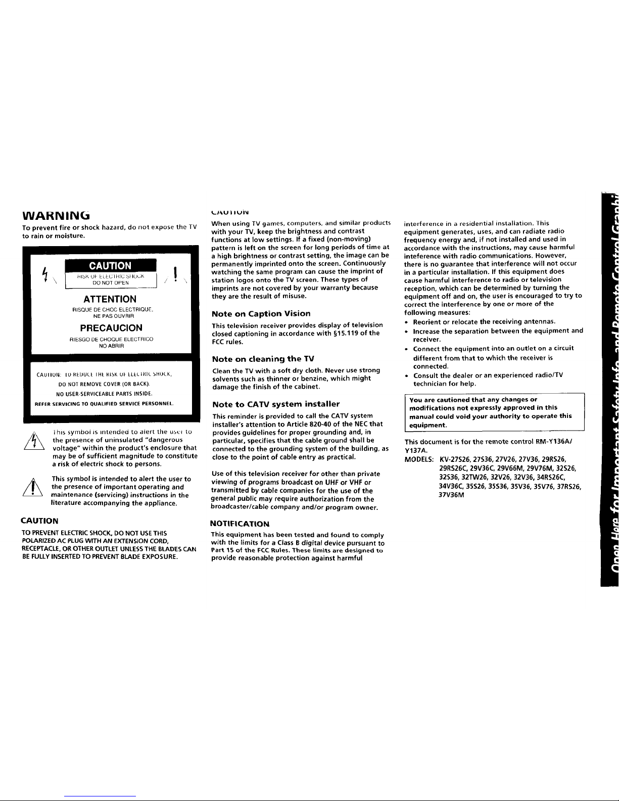
WAHNIN(a
To prevent fire or shock hazard, do not expose the TV
to rain or moisture.
ATTENTION
RISQUE DECHOC ELECTRIQUE,
NE PAS OUVRIR
PRECAUCION
RIESGO DE CHOQUE ELECTRI©O
NO ABRIR
CAUIIUN; IU REUULE IHE HIbK U_ ELLLIHIL bHOLK,
DO NOT REMOVE COVER (OR BACK).
NO USER-SERVICEABLE PARTS INSIDE.
REFER SERVICING TO QUALIFIED SERVICE PERSONNEL.
Ihis symbol is intended to alert the us_'_ to
the presence of uninsulated "dangerous
voltage" within the product's enclosure that
may be of sufficient magnitude to constitute
a risk of electric shock to persons.
This symbol is intended to alert the user to
the presence of important operating and
maintenance (servicing) instructions in the
literature accompanying the appliance.
CAUTION
TO PREVENT ELECTRIC SHOCK, DO NOT USE THIS
POLARIZED AC PLUG WITH AN EXTENSION CORD,
RECEPTACLE, OR OTHER OUTLET UNLESS THE BLADES CAN
BE FULLY INSERTED TO PREVENT BLADE EXPOSURE.
L/-kU i IUiV
When using TV games, computers, and similar products
with your TV, keep the brightness and contrast
functions at low settings. If a fixed (non-moving)
pattern is left on the screen for long periods of time at
a high brightness or contrast setting, the image can be
permanently imprinted onto the screen. Continuously
watching the same program can cause the imprint of
station Iogos onto the TV screen. These types of
imprints are not covered by your warranty because
they are the result of misuse.
Note on Caption Vision
This television receiver provides display of television
closed captioning in accordance with §15.119 of the
FCCrules.
Note on cleaning the TV
Clean the TV with a soft dry cloth. Never use strong
solvents such as thinner or benzine, which might
damage the finish of the cabinet.
Note to CATV system installer
This reminder is provided to call the CATV system
installer's attention to Article 820-40 of the NEC that
provides guidelines for proper grounding and, in
particular, specifies that the cable ground shall be
connected to the grounding system of the building, as
close to the point of cable entry as practical.
Use of this television receiver for other than private
viewing of programs broadcast on UHF or VHF or
transmitted by cable companies for the use of the
general public may require authorization from the
broadcaster/cable company and/or program owner.
NOTIFICATION
This equipment has been tested and found to comply
with the limits for a Class B digital device pursuant to
Part 15 of the FCC Rules, These limits are designed to
provide reasonable protection against harmful
interference in a residential installation. This
equipment generates, uses, and can radiate radio
frequency energy and, if not installed and used in
accordance with the instructions, may cause harmful
inteference with radio communications. However,
there is no guarantee that interference will not occur
in a particular installation. If this equipment does
cause harmful interference to radio or television
reception, which can be determined by turning the
equipment off and on, the user is encouraged to try to
correct the interference by one or more of the
following measures:
• Reorient or relocate the receiving antennas.
• Increase the separation between the equipment and
receiver.
• Connect the equipment into an outlet on a circuit
different from that to which the receiver is
connected.
• Consult the dealer or an experienced radio/TV
technician for help.
I You are cautioned that any changes or
modifications not expressly approved in this
manual could void your authority to operate this
equipment.
This document is for the remote control RM-Y136AI
Y137A.
MODELS: KV-27S26, 27S36, 27V26, 27V36, 29RS26,
29RS26C, 29V36C, 29V66M, 29V76M, 32S26,
32S36, 32TW26, 32V26, 32V36, 34RS26C,
34V36C, 35S26, 35S36, 35V36, 35V76, 37RS26,
37V36M
_ "idDle oJ (.olJ[enr5
Welcome! ........................................ 1
Precautions ...................................... 1
Using This Manual .......................... 1
Connecting and Installing the TV
Connector Types .......................................... 2
Making Connections ...................................2
Connecting directly to cable
or an antenna ....................................... 2
Cable or antenna ...................................... 3
Cable and antenna ................................... 3
Connecting a cable box ............................ 3
Cable box and cable ................................. 3
Connecting an antenna/cable TV system
va_ a_/_R ..........................................4
Connecting to an S¥ideo equipped
VCR ..................................................... 4
Connecting a VCR and TV with a cable
box ...... 5
Connecting to an S Video equipped VCR
with a cable box ................................. 5
Connecting a DBS receiver ...................... 6
Connecting a DBS receiver and a VCR.... 6
Connecting an audio system ................... 7
Connecting an AV receiver ...................... 7
Cozmecting two VCRs tot tape edi_lg
using MONITOR OUT ....................... 8
Using the S-Link function ........................ 9
Connecting a carncorder .......................... 9
Installing the glass door ......................... 10
Adjusting the shelf ................................. 11
Basic Set Up
Inserting batteries ......................................... 12
Using the remote control Select buttons ..... 12
Adjusting sliders .......................................... 12
On Line Help/Instructions .......................... 12
Using your New TV
Settin_ up the TV automatically .................. 13
Watchin_ the TV .......................................... 14
Watching two programs at one
time-- PIP ......................................... 16
Adjusting your SET UP (menus)
Learning menu selection .............................. 18
Using the VIDEO menu ............................... 19
Using the AUDIO menu .............................. 20
Using the TIMER menu ............................... 21
Using [he SET UP menu ............................. 22
Operating video equipment
Settingthe manufacturer's code ................... 24
Operating a cable box or DBS receiver
Pr0gr_g theremote .............................26
Troubleshooting ........................... 27
Specifications ................................ 28
Index .............................................. 31
Owner's Record
The model and serial numbers are located at the rear
O_ the 7Dd, be|ow the Sony |o_o, on the s_.icker, and
also on the TV box (white label). Record these numbers
in the spaces provided below. Refer to them whenever
you call upon your Sony dealer regarding this product,
Model No. KV-
Serial No.
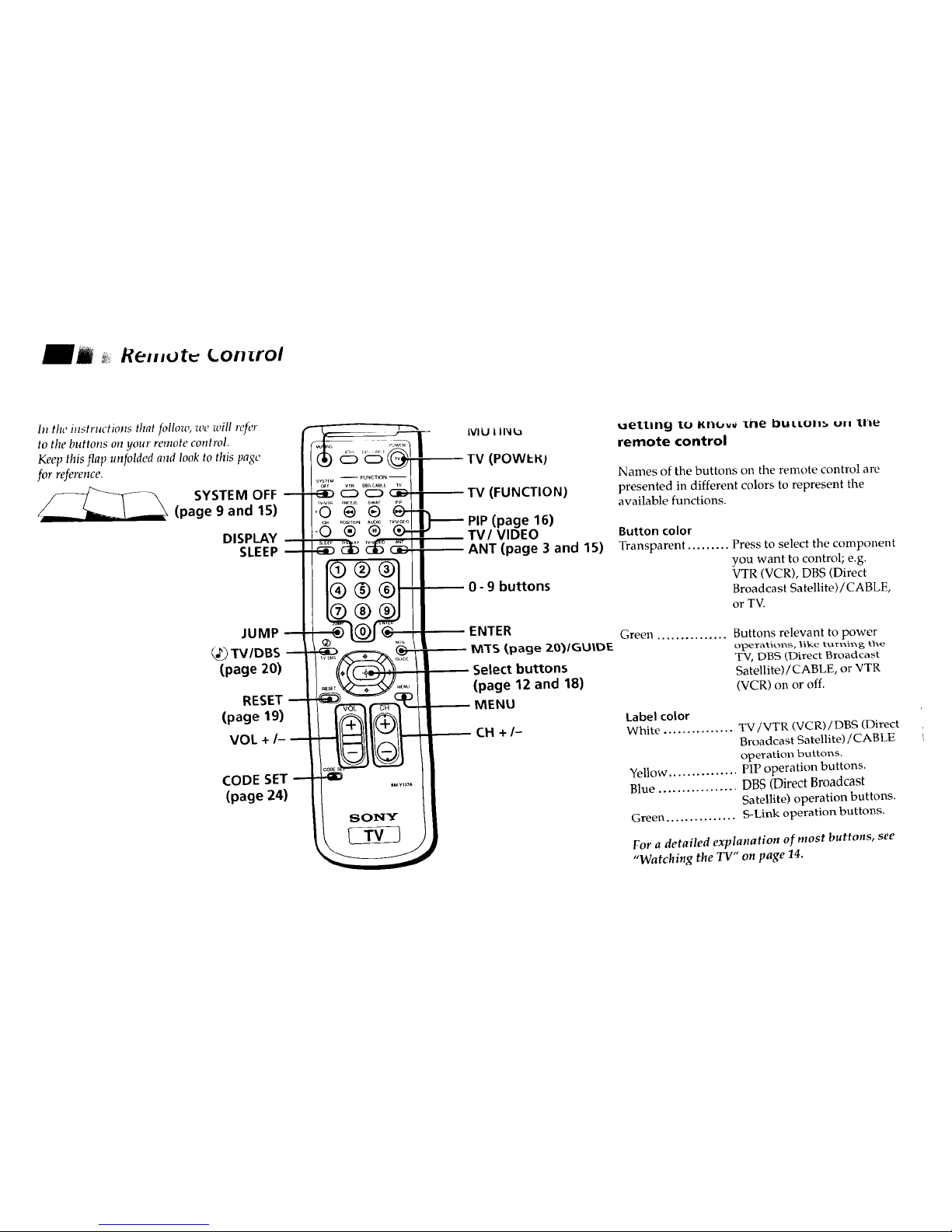
Remut Lon rol
In the instructions that fidlow, we will refer
to the buttons on your remote control.
Keep this flap unfolded and look to this page
for reference.
SYSTEM OFF
(page 9 and 15)
DISPLAY
SLEEP
JUMP
TV/DBS
(page 20)
RESET
(page 19)
VOL +/-
CODE SET
(page 24)
IVlU 1li_lla
(POWl:t_)
(FUNCTION)
PIP (page 16)
VIDEO
(page 3 and 15)
9 buttons
ENTER
M_S (,page ZO_/GUIDIE
Select buttons
(page 12 and 18)
MENU
CH +/-
uettlll_l IO Iiril.,vv ][BebLILLLIII_, Ull l[l'/_
remote control
Names of the buttons on the remote control are
presented in different colors to represent the
available functions.
Button color
Transparent ......... Press to select the component
you want to control; e.g.
VTR (VCR), DBS (Direct
Broadcast Satellite) / CABLE,
or TV.
Green ..............
Buttons relevant to power
operatkons, tlke turl_i_g tl_e
TV, DBS (Direct Broadcast
Satellite)/CABLE, or VTR
(VCR) on or off.
Label color
White ............... TV/VTR (VCR) / DBS (Direct
Broadcast Satellite)/CABLE
operation buttons.
Yellow ............... PIP operation buttons.
Blue ................. DBS (Direct Broadcast
Satellite) operation buttons.
Green ............... S-Link operation buttons.
For a detailed explanation of most buttons, see
"Watching the TV" on page 14.
WeicuJ J_ _.
Freca u tioHb
_ USII}y lhlS Malludl
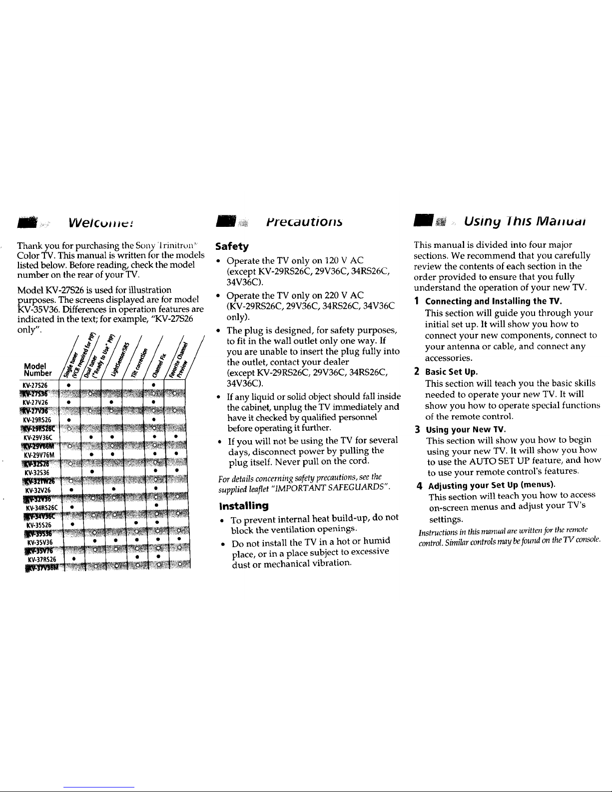
Thank you for purchasing the Sony '1rinitron
Color TV. This manual is written for the models
listed below. Before reading, check the model
number on the rear of your TV.
Model KV-27S26 is used for illustration
purposes. The screens displayed are for model
KV-35V36. Differences in operation features are
indicated in the text; for example, "KV-27S26
only".
Model
Number
KV-27S26
KV-27V26
KV-29RS26
Kv-zgv36c
KV-ZgV76M
KV-32S36
KV-32V26
KV-34RS26C
KV-35S26
KV-35V36
KV-37RS26
Safety
• Operate the TV only on 120 V AC
(except KV-29RS26C, 29V36C, 34RS26C,
34V36C).
• Operate the TV only on 220 V AC
(KV-29RS26C, 29V36C, 34RS26C, 34V36C
only).
• The plug is designed, for safety purposes,
to fit in the wall outlet only one way. If
you are unable to insert the plug fully into
the outlet, contact your dealer
(except KV-29RS26C, 29V36C, 34RS26C,
34V36C).
• If any liquid or solid object should fall inside
the cabinet, unplug the TV immediately and
have it checked by qualified personnel
before operating it further.
• If you will not be using the TV for several
days, disconnect power by pulling the
plug itself. Never pull on the cord.
Fordetails concerning safety precautions, see the
supplied leaflet "IMPORTANT SAFEGUARDS".
Installing
• To prevent internal heat build-up, do not
block the ventilation openings.
• Do not install the TV in a hot or humid
place, or in a place subject to excessive
dust or mechanical vibration.
This manual is divided into four major
sections. We recommend that you carefully
review the contents of each section in the
order provided to ensure that you fully
understand the operation of your new TV.
1 Connecting and Installing the TV.
This section will guide you through your
initial set up. It will show you how to
connect your new components, connect to
your antenna or cable, and connect any
accessories.
2 Basic Set Up.
This section will teach you the basic skills
needed to operate your new TV. It will
show you how to operate special functions
of the remote control.
3 Using your New TV.
This section will show you how to begin
using your new TV. It will show you how
to use the AUTO SET UP feature, and how
to use your remote control's features.
4 Adjusting your Set Up (menus).
This section will teach you how to access
on-screen menus and adjust your TV's
settings.
Instructions inthis manual arewritten for theremote
control.Similarcontrolsmay befound on the TV console.
/_ LoJ_e_.U/Ig _na Installi[_y _lie 1V
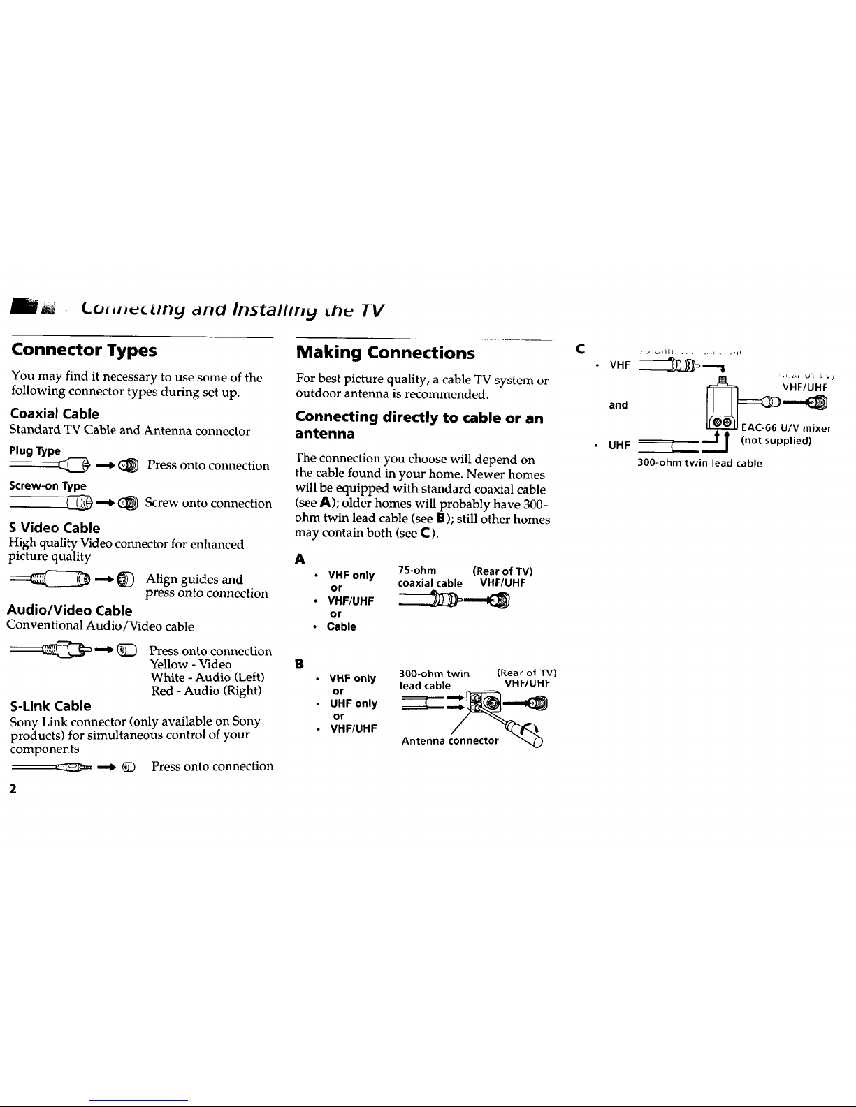
Connector Types
You may find it necessary to use some of the
following connector types during set up.
Coaxial Cable
Standard TV Cable and Antenna connector
PlugType
_C_ _ _ Press onto connection
Screw-on Type
--_ (_ Screw onto connection
S Video Cable
High quality Video connector for enhanced
picture quality
_ _) Align guides and
press onto connection
Audio/Video Cable
Conventional Audio/Video cable
_ _) Press onto connection
Yellow - Video
White - Audio (Left)
Red - Audio (Right)
S-Link Cable
Sony Link connector (only available on Sony
products) for simultaneous control of your
components
_¢:_EI_ _ K) Press onto connection
Making Connections
For best picture quality, a cable TV system or
outdoor antenna is recommended.
Connecting directly to cable or an
antenna
The connection you choose will depend on
the cable found in your home. Newer homes
will be equipped with standard coaxial cable
(see A); older homes will probably have 300-
ohm twin lead cable (see B); still other homes
may contain both (see C ).
A
• VHF only 75-ohm (Rear of TV)
coaxial cable VHF/UHF
or
. VHF/UHF __
or
• Cable
B
• VHF only 300-ohm twin (Rear ot lV)
lead cable VHF/U HF
or _::::.__
• UHFonly
or
• VHF/UHF
Antenna connector "_
C
VHF _--._
anO
EAC-66 U/V mixer
___.J_ (not supplied)UHF
B _
300-ohm twin lead cable

Cable or antenna
Most simple connection. Connection is made
directly from the cable or antenna to the TV.
Cable
(Rear of TV)
VHF/UHF
Cable and antenna
• KV-27S36, 27V36, 29V36C, 29V76M, 32S36, 32V36,
34V36C, 35S36, 35V36, 35V76, 37V36M only
You may find it convenient to use the
following set up if your cable provider does
not feature local channels that you are able to
receive using an antenna.
(Rear of TV)
AUX
CATVcable
(No connection "TO
CONVERTER"in thiscase)
TO CONVERTER
Antennacable
VHFIUHF
Select Cable or ANT mode by pressing ANT on
the remote control.
Connecting a cable box
Some pay cable TV systems use scrambled or
encoded signals that require a cable box* to
view all channels.
(Rearof TV)
Cable VHF/UHF
I |
*Cable box
Note:
• If you will be controlling all channel
selection through your cable box you
should consider using the CHANNEL FIX
feature discussed on page 22.
Cable box and cable
• KV-27S36, 27V36, 29V36C, 29V76M, 32S36, 32V36,
34V36C, 35S36, 35V36, 35V76, 37V36M only
Some pay cable TV systems use scrambled or
encoded signals requiring a cable box* only for
certain channels (e.g. HBO, SHOWTIME, etc.).
* Cable bux (Kea_ of lv)
AUX
I
I scrambleo /
I channels | TO CONVERTER
1
75-ohm coaxial )
cable (not supplied) i (signal)
i
CATV cable
(unscrambled channnels) VHF/UHF
For this set up, you can switch between scramblec
channels (through your cable box), and normal
(CATV) channels by pressing ANT on your
remote control.
* Your Sony remote control can be prograrnrned
to operate your cable box (see page 26).
Notes:
• You cannot watch the signal through the
"AUX" input as a window picture when
using Picture-in-Picture (PIP).
• If you are connecting a cable box through
the"AUX" input and would like to switch
between the "AUX" and normal (CATV) input
you should consider using the CHANNEL FI2
feature dks_ssed on page 22.
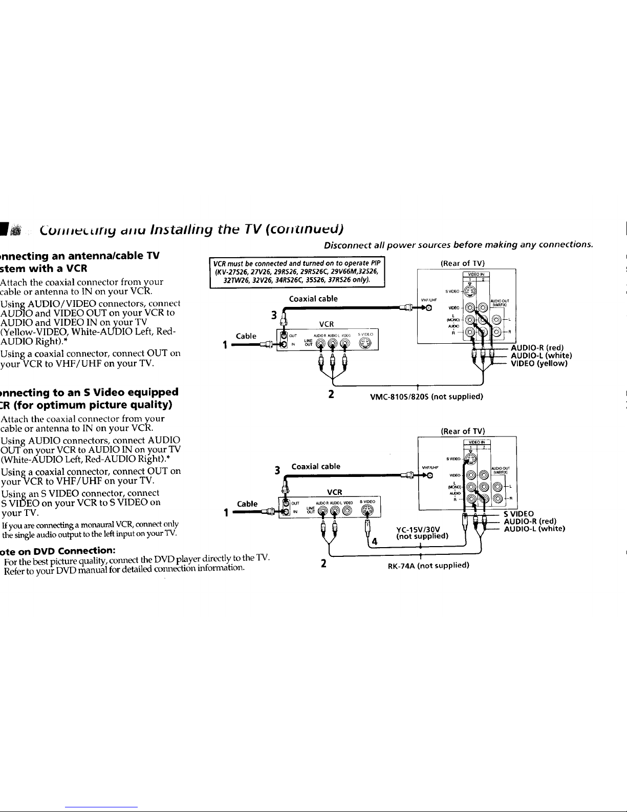
Cui_r_t d_u Installing the TV (coH_nu_d)
Disconnect all power sources before making any connections.
,nnecting an antennalcable TV
stem with a VCR
Attach the coaxial connector from your
cable or antenna to IN on your VCR.
Using AUDIO/VIDEO connectors, connect
AUDIO and VIDEO OUT on your VCR to
AUDIO and VIDEO IN on your TV
(Yellow-VIDEO, White-AUDIO Left, Red-
AUDIO Right).*
Using a coaxial connector, connect OUT on
your VCR to VHF/UHF on your TV.
_nnecting to an S Video equipped
.'R (for optimum picture quality)
Attach the coaxial connector from your
cable or antenna to IN on your VCR.
Using AUDIO connectors, connect AUDIO
OUT on your VCR to AUDIO IN on your TV
(White-AUDIO Left, Red-AUDIO Right).*
Using a coaxial connector, connect OUT on
yourVCR to VHF/UHF on your TV.
Using an S VIDEO connector, connect
S VIDEO on your VCR to S VIDEO on
your TV.
Ifyou areconnectinga monaural VCR, connect only
the single audio outputto the leftinput on your TV.
ote on DVD Connection:
For the best picture quality, connect the DVD player directly to the TV.
Refer to your DVD manual for detailed connection information.
VCR must be connected and turned on to operate PIP I
(KV.27526, 27V26, 29RS26, 29RS26C, 29V66M,32S26,
!
32TW26, 32V26, 34R$26C, 35526, 37R526 only).
Coaxial cable
VCR
r AUO_RAUD_LVIDEO SVIDEO
1 @
(Rear of TV)
s VIDEO
VHF UHF AUDIO OUT
_. _ _.o .....
L
(MONO) L
^upo
R
AUDIO-R (red)
AUDIO-L (white)
VIDEO (yellow}
!
2 VMC-810S/820S (not supplied)
(Rear of TV)
+ .......
3 Coaxial cable ._ AUD,O00,
w7 (V_lX}
VCR _ .
S VIDEO
V _ AUDIO-R (red)
YC-15V/30V AUDIO-L (white)
(not supplied)
4 i
!
2 RK-74A (not supplied)
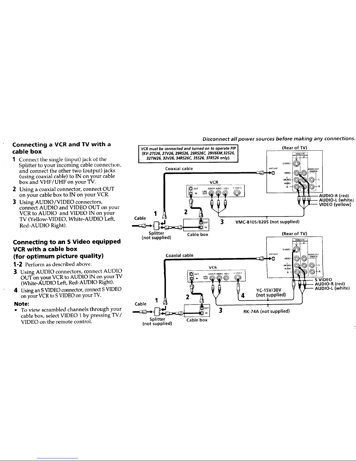
Connecting a VCR and TV with a
cable box
1 Connect the single (input) jack of the
Splitter to your incoming cable connection,
and connect the other two (output) jacks
(using coaxial cable) to IN on your cable
box and VHF/UHF on your TV.
2 Using a coaxial connector, connect OUT
on your cable box to IN on your VCR.
3 Using AUDIO/VIDEO connectors,
connect AUDIO and VIDEO OUT on your
VCR to AUDIO and VIDEO IN on your
TV (Yellow-VIDEO, White-AUDIO Left,
Red-AUDIO Right).
Connecting to an S Video equipped
VCR with a cable box
(for optimum picture quality)
1-2 Perform as described above.
3 Using AUDIO connectors, connect AUDIO
OUT on your VCR to AUDIO IN on your TV
(White-AUDIO Left, Red-AUDIO Right).
4 Using an S VIDEO connector, connect S VIDEO
on your VCR to S VIDEO on your TV.
Note:
• To view scrambled channels through your
cable box, select VIDEO I by pressing TV/
VIDEO on the remote control.
Disconnect all power sources before making any connections.
I VCRmust be connected and turned on to operate PIP I
(KV-27S26, 27V26, 29RS26, 29R$26C, 29V66M,32S26,
I
32TW26, 32V26, 34RS26C, 35S26, 37R$26 only).
Coaxial cable
(Rear of TV)
VCR
Splitter Cable box
(not supplied)
:oaxial cable
VCR
Cable 1 ;_ _
Splitter Cable box
(not suppUed)
,AUDIO OUT
(v_lx)
- AUDIO-R (red)
AUDIO-L (white)
VIDEO (yellow)
f
VMC-810S/820S (not supplied)
(Rear of TV)
HF AU_"OOU_
(VAP#FIX)
_'_
,,u'_
S VIDEO
AUDIO-R (red)
YC-15V/30V AUDIO-L (white)
(not supplied)
1
!
RK-74A (not supplied)
(_Olili_L{lll_ dilU irlS[allirlg [De
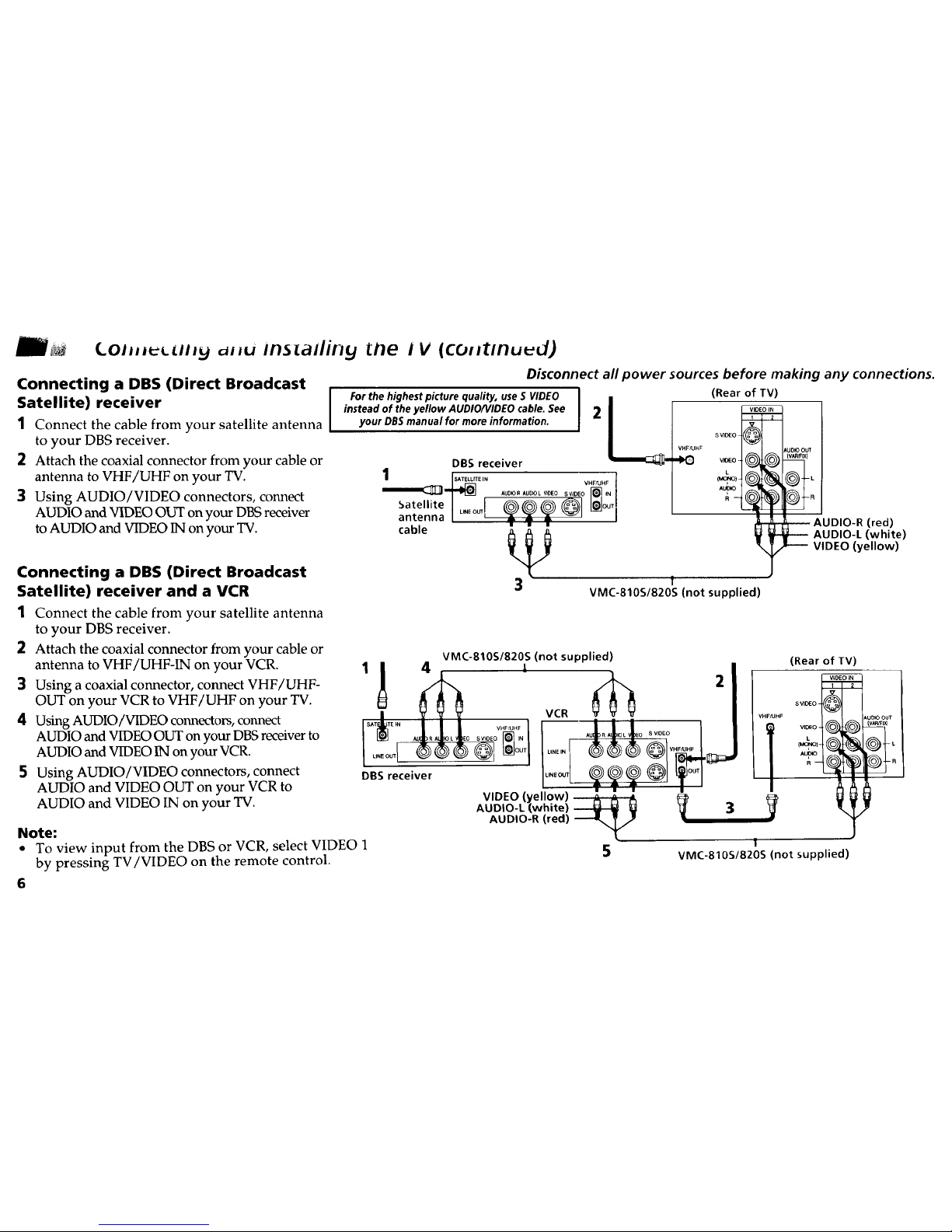
Connecting a DBS (Direct Broadcast
Satellite) receiver
1 Connect the cable from your satellite antenna
to your DBS receiver.
2 Attach the coaxial connector from your cable or
antenna to VHF/UHF on your TV.
3 Using AUDIO/VIDEO connectors, connect
AUDIO and VIDEO OUT on your DBS receiver
to AUDIO and VIDEO IN on your TV.
Connecting a DBS (Direct Broadcast
Satellite) receiver and a VCR
1 Connect the cable from your satellite antenna
to your DBS receiver.
2 Attach the coaxial connector from your cable or
antenna to VHF/UHF-IN on your VCR.
3 Using a coaxial connector, connect VHF/UHF-
OUT on your VCR to VHF/UHF on your TV.
4 Using AUDIO/VIDEO connectors, connect
AUDIO and VIDEO OUT on your DBS receiver to
AUDIO and VIDEO IN on your VCR.
5 Using AUDIO/VIDEO connectors, connect
AUDIO and VIDEO OUT on your VCR to
AUDIO and VIDEO IN on your TV.
Note:
• To view input from the DBS or VCR, select VIDEO 1
by pressing TV/VIDEO on the remote control.
6
I V (coHtmuud)
Disconnect all power sources before making any connections.
For the highest picture quality, use S VIDEO I II (Rear of TV)
instead of the yellow AUDIONIDEO cable. See I 2your DBS manual for more information.
VHF&IIIF
DBS receiver
1 rsAT_,_ v..... 1
Satellite| _ l_]OUT[
antenna I ..... I _ _m I
cable , , , (red)
_ AUDIO-L (white)
VIDEO (yellow)
3 T
VMC-810S/820S(not supplied)
ls_ 4 . I
DBS receiver
VIDEO (yellow) _
AUDIO-L (white)
AUDIO-R (red)
5
VMC-810S/820S (not supplied)
VCR VHFAJI-CF
3
(Rear of TV)
VMC-810S/820S (not supplied)
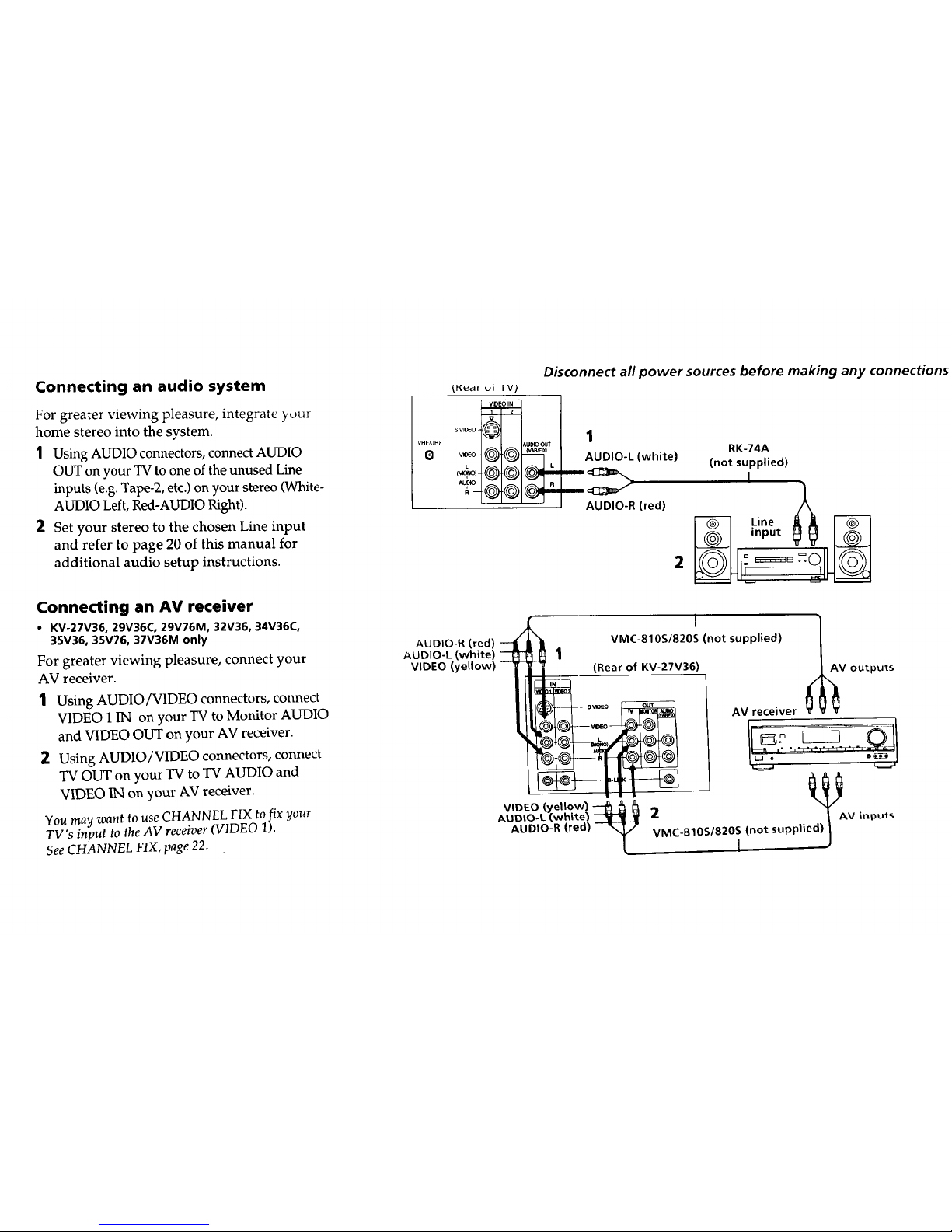
Connecting an audio system
For greater viewing pleasure, integrate your
home stereo into the system.
1 Using AUDIO connectors, connect AUDIO
OUT on your TV to one of the unused Line
inputs (e.g. Tape-2, etc.) on your stereo (White-
AUDIO Left, Red-AUDIO Right).
2 Set your stereo to the chosen Line input
and refer to page 20 of this manual for
additional audio setup instructions.
Connecting an AV receiver
• KV-27V36, 29V36C, 29V76M, 32V36, 34V36C,
35V36, 35V76, 37V36M only
For greater viewing pleasure, connect your
AV receiver.
1 Using AUDIO/VIDEO connectors, connect
VIDEO 1 IN on your TV to Monitor AUDIO
and VIDEO OUT on your AV receiver.
2 Using AUDIO/VIDEO connectors, connect
TV OUT on your TV to TV AUDIO and
VIDEO IN on your AV receiver.
You may want to use CHANNEL FIX to fix your
TV's input to the AV receiver (VIDEO 1).
See CHANNEL FIX, page 22.
_l'(etdl ui I V)
s video
VHF/UHF AUDI O OUT
Disconnect all power sources before making any connections.
1
RK-74A
AUDIO-L (white) (not supplied)
,
AUDIO-R (red)
Line [_
input
2 IL= I
AUDIO-R (red) -_
AUDIO-L (white) --_ 1
VIDEO (yellow)
VIDEO (,yellow) _ I_ h
AUDIO-L (white) --4_H_I_
AUDIO-R (red) -_
(Rear of KV-27V36)
VMC-810S/820S (not supplied)
outputs
AV receiver
2 ed)_/_v inputs
VMC-810S1820S (not suppli
I
.o Je¢ting d Jd Ins alling I V (cunrlnued)
Disconnect all power sources before making any connection
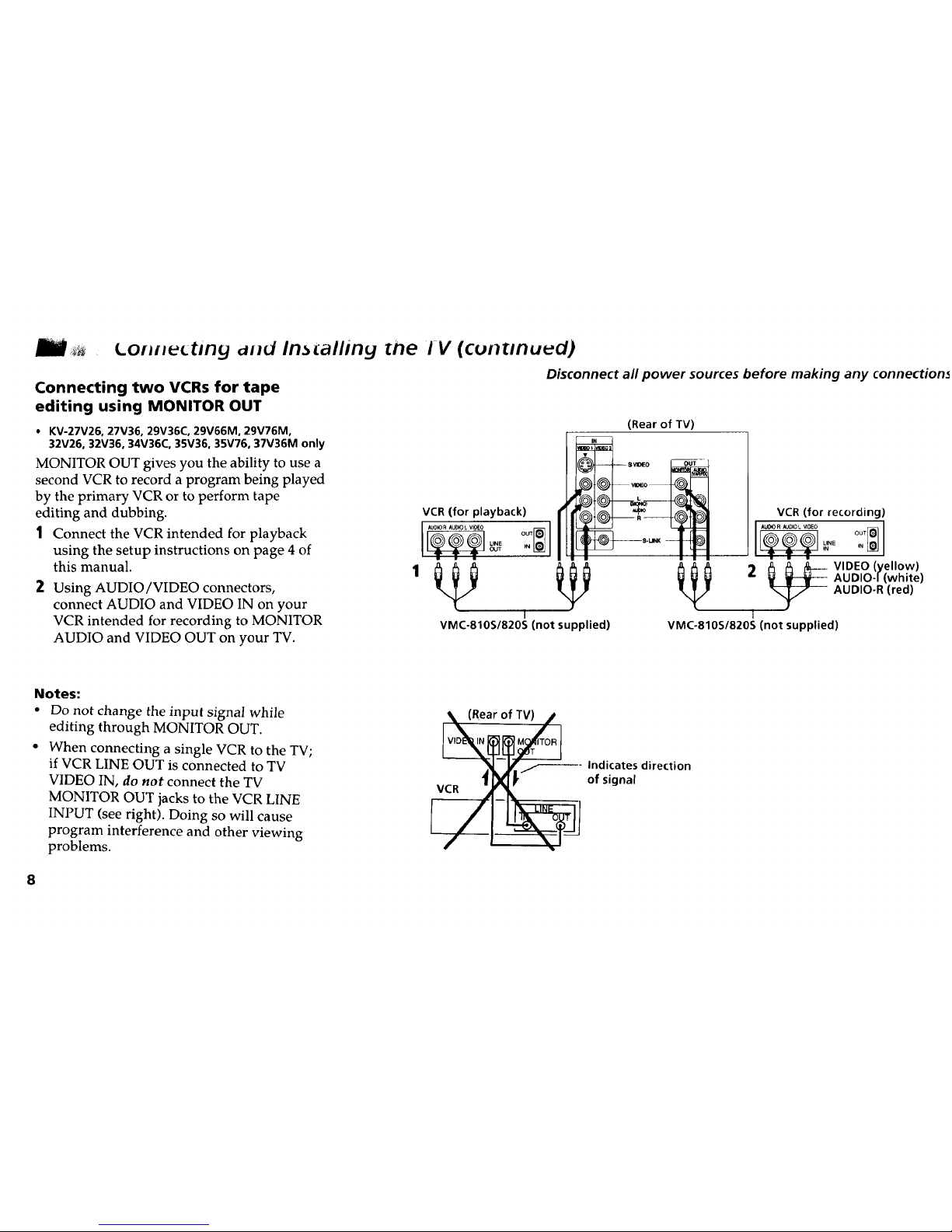
Connecting two VCRs for tape
editing using MONITOR OUT
• KV-27V26, 27V36, 29V36C, 29V66M, 29V76M,
32V26, 32V36, 34V36C, 35V36, 35V76, 37V36M only
MONITOR OUT gives you the ability to use a
second VCR to record a program being played
by the primary VCR or to perform tape
editing and dubbing.
1 Connect the VCR intended for playback
using the setup instructions on page 4 of
this manual.
2 Using AUDIO/VIDEO connectors,
connect AUDIO and VIDEO IN on your
VCR intended for recording to MONITOR
AUDIO and VIDEO OUT on your TV.
(Rear of TV)
VCR (for playback)
AUO_OR AUD_ VlOEO I
J
I
VMC-810S/820S (not supplied)
VCR/,for recording)
_E _N
2 AUDIO-/lwhite)
AUDIO-R (red)
VMC-810S/820S (not supplied)
Notes:
• Do not change the input signal while
editing through MONITOR OUT.
• When connecting a single VCR to the TV;
if VCR LINE OUT is connected to TV
VIDEO IN, do not connect the TV
MONITOR OUT jacks to the VCR LINE
INPUT (see right). Doing so will cause
program interference and other viewing
problems.
VCR
(Rear of TV)
Indicates direction
of signal
 Loading...