


KDL-26S2010E
Sony KDL-26S2010E, KDL-32S2000E, KDL-32S2010E, KDL-40S2010E, KDL-46S2010E Service Manual
...
- 1 -
WAX2
RM-ED005
SERVICE MANUAL
WAX2
CHASSIS
MODEL
COMMANDER DEST
MODEL
COMMANDER DEST
KDL-26S2000U
RM-ED005 UK
KDL-32S2000U
RM-ED005 UK
KDL-40S2000U
RM-ED005 UK
KDL-46S2000U
RM-ED005 UK
KDL-26S2010U
RM-ED005 UK
KDL-32S2010U
RM-ED005 UK
KDL-40S2010U
RM-ED005 UK
KDL-46S2010U
RM-ED005 UK
KDL-26S2020U
RM-ED005 UK
KDL-32S2020U
RM-ED005 UK
RM-ED005
FLAT PANEL COLOR TV
KDL-26S2000 / KDL-32S2000 / KDL-40S2000 / KDL-46S2000
KDL-26S2010 / KDL-32S2010 / KDL-40S2010 / KDL-46S2010
KDL-26S2020 / KDL-32S2020
KDL-26S2000E
RM-ED005 AEP
KDL-32S2000E
RM-ED005 AEP
KDL-40S2000E
RM-ED005 AEP
KDL-46S2000E
RM-ED005 AEP
KDL-26S2010E
RM-ED005 AEP
KDL-32S2010E
RM-ED005 AEP
KDL-40S2010E
RM-ED005 AEP
KDL-46S2010E
RM-ED005 AEP
KDL-26S2020E
RM-ED005 AEP
KDL-32S2020E
RM-ED005 AEP

- 2 -
WAX2
RM-ED005
TABLE OF CONTENTS
Section Title Page Section Title Pa ge
Caution ................................................................ 3
Specifications ...................................................... 4
Connectors .......................................................... 6
Self Diagnosis ..................................................... 7
1. GENERAL ................................................................... 8
2. DISASSEMBLY
2-1. Rear Cover Removal ........................................... 18
2-2. Stand Removal .................................................... 18
2-3. Vesa Bracket Removal ........................................ 19
2-4. Shield Cover Removal ........................................ 19
2-5. Speaker Removal ................................................ 20
2-6. AC Inlet Removal ............................................... 20
2-7. AE and TUE Board Removal ............................. 21
2-8. BE and FEE Board Removal .............................. 21
2-9. G1 or G2 Board Removal................................... 22
2-10. H1E Board Removal ........................................... 22
2-11. H2E or H46E Board Removal ............................ 23
2-12. H3E Board Removal ........................................... 23
2-13. Shield Base Removal .......................................... 24
2-14. LCD Panel Removal ........................................... 24
3. SET-UP ADJUSTMENTS
3-1. How to enter Service Mode ............................... 25
3-2. Signal Level Adjustment .................................... 25
3-2-1. Set up of AD calibration1 adjustment for
terrestrial analog ............................................... 25
3-2-2. Y signal calibration1 adjustment for
terrestrial analog ............................................... 25
3-2-3. Set up of C signal calibration1 adjustment for
terrestrial analog ............................................... 25
3-2-4. C signal calibration1 adjustment for
terrestrial analog ............................................... 26
3-2-5. Set up of AD calibration1 adjustment for
video ................................................................ 26
3-2-6. Y signal calibration1 adjustment for video ...... 26
3-2-7. Set up of C signal calibration1 adjustment for
video ................................................................ 26
3-2-8. C signal calibration1 adjustment for video ...... 26
3-2-9. Set up of AD calibration2 adjustment for
video ................................................................ 26
3-2-10. Y signal calibration2 adjustment for video .... 26
3-2-11. Set up of C signal calibration2 adjustment for
video .............................................................. 27
3-2-12. C signal calibration2 adjustment for video .... 27
3-3. Gamma Adjustment ........................................... 27
3-3-1. Set up mode for Gamma Adjustment .............. 27
3-3-2. Set up Trident internal SG and brightness
measurement .................................................... 27
3-4. White Balance Adjustment ................................. 27
3-4-1. Set up mode for White Balance Adjustment ... 27
3-4-2. White Balance of colour temperature “High” .. 27
3-5. Panel Replacement ............................................. 29
3-6. Board Replacement ............................................ 29
3-6-1. AE Board Replacement ................................... 29
3-6-2. BE Board Replacement .................................... 29
4. DIAGRAMS
4-1. Block Diagrams(1) ............................................. 30
Block Diagrams(2) ............................................. 31
Block Diagrams(3) ............................................. 32
Block Diagrams(4) ............................................. 33
4-2. Circuit Board Location ........................................ 33
4-3. Schematic Diagrams and Printed Wiring
Boards ................................................................. 33
AE Board Schematic Diagram ............................ 34
AE Printed Wiring Board ................................. 38
BE Board Schematic Diagram ............................ 40
BE Printed Wiring Board ................................... 50
FEE Board Schematic Diagram .......................... 52
FEE Printed Wiring Board ................................. 58
G2 Board Schematic Diagram (40 & 46 inch) ... 59
G2 Printed Wiring Board (40 & 46 inch) ......... 60
H1E Board Schematic Diagram .......................... 62
H1E Printed Wiring Board ............................... 63
H2E Board Schematic Diagram .......................... 62
H2E Printed Wiring Board ............................... 63
H3E Board Schematic Diagram .......................... 62
H3E Printed Wiring Board ............................... 63
H46E Board Schematic Diagram (46 inch) ........ 64
H46E Printed Wiring Board (46 inch) ................ 63
TUE Schematic Diagram .................................... 64
TUE Printed Wiring Board ............................... 66
4-4. Semiconductors .................................................. 67
5. EXPLODED VIEWS
5-1. Chassis................................................................ 69
5-2. Rear Cover, Stand and Vesa Bracket .................. 71
6. ELECTRICAL PARTS LIST .................................. 73
SAFETY-RELATED COMPONENT WARNING !!
COMPONENTS IDENTIFIED BY SHADING AND MARKED
ON
THE SCHEMATIC DIAGRAMS, EXPLODED VIEWS AND IN THE
PARTS LIST ARE CRITICAL FOR SAFE OPERATION. REPLACE
THESE COMPONENTS WITH SONY PARTS WHOSE PART
NUMBERS APPEAR AS SHOWN IN THIS MANUAL OR IN
SUPPLEMENTS PUBLISHED BY SONY.
WARNING !!
AN ISOLATION TRANSFORMER SHOULD BE USED DURING
ANY SERVICE WORK TO AVOID POSSIBLE SHOCK HAZARD
DUE TO LIVE CHASSIS, THE CHASSIS OF THIS RECEIVER IS
DIRECTLY CONNECTED TO THE POWER LINE.
- 3 -
WAX2
RM-ED005
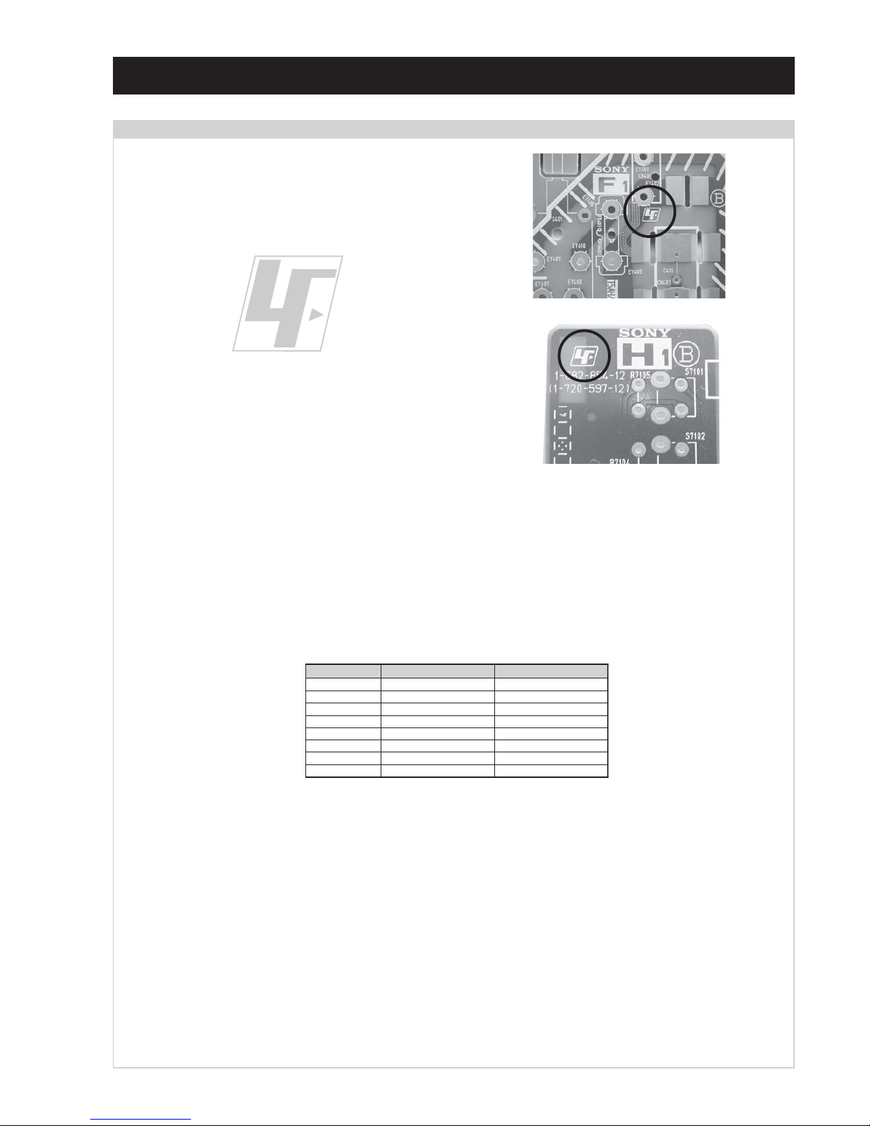
The circuit boards used in these models have been processed using
Lead Free Solder. The boards are identified by the LF logo located
close to the board designation e.g. F1, H1 etc [ see examples ]. The
servicing of these boards requires special precautions to be taken as
outlined below.
CAUTION
Lead Free Soldered Boards
example 1
example 2
It is strongly recommended to use Lead Free Solder material in order to guarantee optimal quality of new solder joints. Lead Free Solder is
available under the following part numbers :
Due to the higher melting point of Lead Free Solder the soldering iron tip temperature needs to be set to 370 degrees centigrade. This requires
soldering equipment capable of accurate temperature control coupled with a good heat recovery characteristics.
For more information on the use of Lead Free Solder, please refer to http://www.sony-training.com
rebmuntraP retemaiD skrameR
91-500-046-7mm3.0gK52.0
02-500-046-7mm4.0gK05.0
12-500-046-7mm5.0gK05.0
22-500-046-7mm6.0gK52.0
32-500-046-7mm8.0gK00.1
42-500-046-7mm0.1gK00.1
52-500-046-7mm2.1gK00.1
62-500-046-7mm6.1gK00.1
- 4 -
WAX2
RM-ED005
LEDOMMETI metsySnoisiveleT metsySoeretS egarevoClennahC metsySroloC
ET-BVD,L,I,K/D,H/G/B
MACIN/NAMREG
oeretS
21E-20E:FHV
96E-12E:FHU
02S-10S:VTAC
14S-12S:REPYH
96R-12
R,21R-1R:K/D
96F-12F,Q-B,01F-2F:L
96B-12BFHU:I
MACES,LAP
34.4/85.3CSTN
)YLNOOEDIV(
LM@PM2-GEPM
UT-BVD,IoeretSM
ACIN96B-12B:FHU
MACES,LAP
34.4/85.3CSTN
)YLNOOEDIV(
LM@PM2-GEPM
eziSerutciPdetcejorP
lenaP)yalpsiDlatsyrCdiuqiL(DCL
)sehcni62(mc1.66xorppA
)sehcni23(mc1.08xorppA
)sehcni
04(mc6.101xorppA
.)sehcni64(mc9.611xorppA
tuptuOdnuoS
rekaepstfeLdnathgiR
refoow-buS
)SMR(W01x2
]RAER[slanimreTtuptuO/tupnI snoitacificepSlareneG
rotcennocoruEnip-12:1
)dradnatsCELENEC(
.slangisoediVdnaoiduArofstupnI
.BGRrofstupnI
oiduAdnaoediVVTfostu
ptuO
.slangis
stnemeriuqeRrewoPV042-022
/noitpmusnoCrewoP
ybdnatS
)hcni62(W3.0/W001xorppA
)hcni23(W3.0/W521xorppA
)hcni04(W3.0/W081xorppA
)hcni64(
W3.0/W052xorppA
rotcennocoruEnip-12:2
)dradnatsCELENEC(
.slangisoediVdnaoiduArofstupnI
.BGRrofstupnI
slangisoiduAdnaoediV
fostuptuO
.ecafretnikniLtramS.)elbatceleS(
snoisnemiD
)dnatshtiwhcni62(mm912x615x856xorppA
)dnatstuohtiwhcni62(mm49x074x856xorppA
)dnatshtiwhcni23(
mm912x395x297xorppA
)dnatstuohtiwhcni23(mm99x645x297xorppA
)dnatshtiwhcni04(mm433x617x889xorppA
)dnatstu
ohtiwhcni04(mm301x466x889xorppA
)dnatshtiwhcni64(mm433x508x0211xorppA
)dnatstuohtiwhcni64(mm611x557x021
1xorppA
thgieW
)dnatshtiwhcni62(gk31xorppA
)dnatstuohtiwhcni62(gk11xorppA
)dnatshtiwhcni23(gk71xorppA
)dnatstuoht
iwhcni23(gk51xorppA
)dnatshtiwhcni04(gk72xorppA
)dnatstuohtiwhcni04(gk12xorppA
)dnatshtiwhcni64(gk43xorp
pA
)dnatstuohtiwhcni64(gk82xorppA
skcaJonohP
rofelbairavsrotcennoCtuptuO
.slangiSoiduA
seirosseccAdeilppuS
)1(rednammoCetomeR500DE-MR
)2(yrettab60RdetangisedCEI
)1(daeLsniaM
tupnIIMDH.rotcennoCIMDH
serutaeFrehtO
,renuTT-BVD,lenaPDCLelgnAediW
thgiL,txeteleT,kniLtramS,retliFbmoCD3
,tupniIMDH,latigiDEBB,
ezeerfPniP,rosneS
.tupniCP
tupnICP.rotcennoCbuS-DniP51
MACeludoMsseccAlanoitidnoC
]EDIS[slanimreTtuptuO/tupnI lortnocderarfnI:metsyslortnocetomeR
kcajenohpdaeHkcajinimoeretS
stnemeriuqerrewoP
cdV3
noitangisedCEIseirettab2
)AAezis(60R
tupnioiduAskcajonohP
tupnioediVkcajonohP
tupnioediVSNIDinimnip4
.ecitontuohtiwegnahcottcejbuserasnoitacificepsdnangiseD
- 5 -
WAX2
RM-ED005
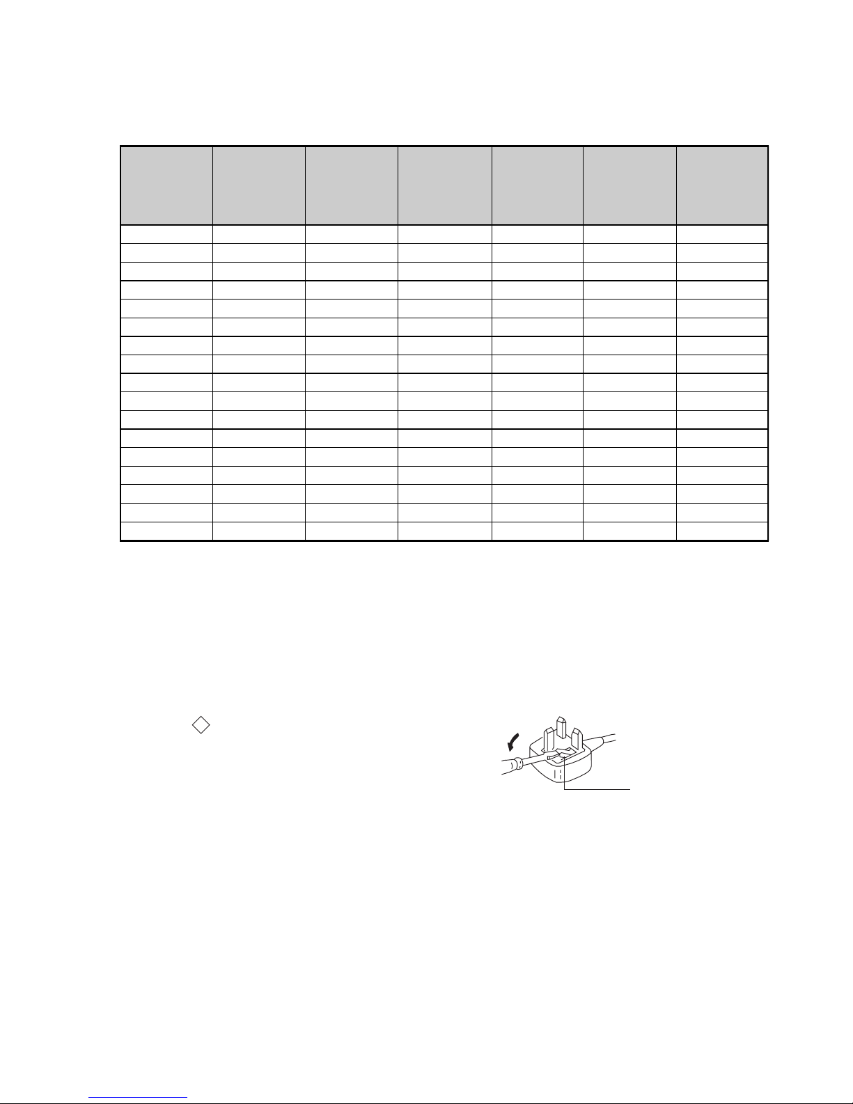
How to replace the fuse.
Open the fuse compartment with
a screwdriver blade and replace
the fuse.
FUSE
WARNING (UK Models only)
The flexible mains lead is supplied connected to a B.S. 1363 fused
plug having a fuse of 13 AMP rating. Should the fuse need to be
replaced, use a 13AMP FUSE approved by ASTA to BS 1362, ie one
that carries the
ASA
T
mark.
IF THE PLUG SUPPLIED WITH THIS APPLIANCE IS NOT SUITABLE FOR THE OUTLET SOCKETS IN YOUR HOME, IT SHOULD
BE CUT OFF AND AN APPROPRIATE PLUG FITTED. THE PLUG
SEVERED FROM THE MAINS LEAD MUST BE DESTROYED AS A
PLUG WITH BARED WIRES IS DANGEROUS IF ENGAGED IN A
LIVE SOCKET.
When an alternative type of plug is used, it should be fitted with a
13 AMP FUSE, otherwise the circuit should be protected by a
13AMP FUSE at the distribution board.
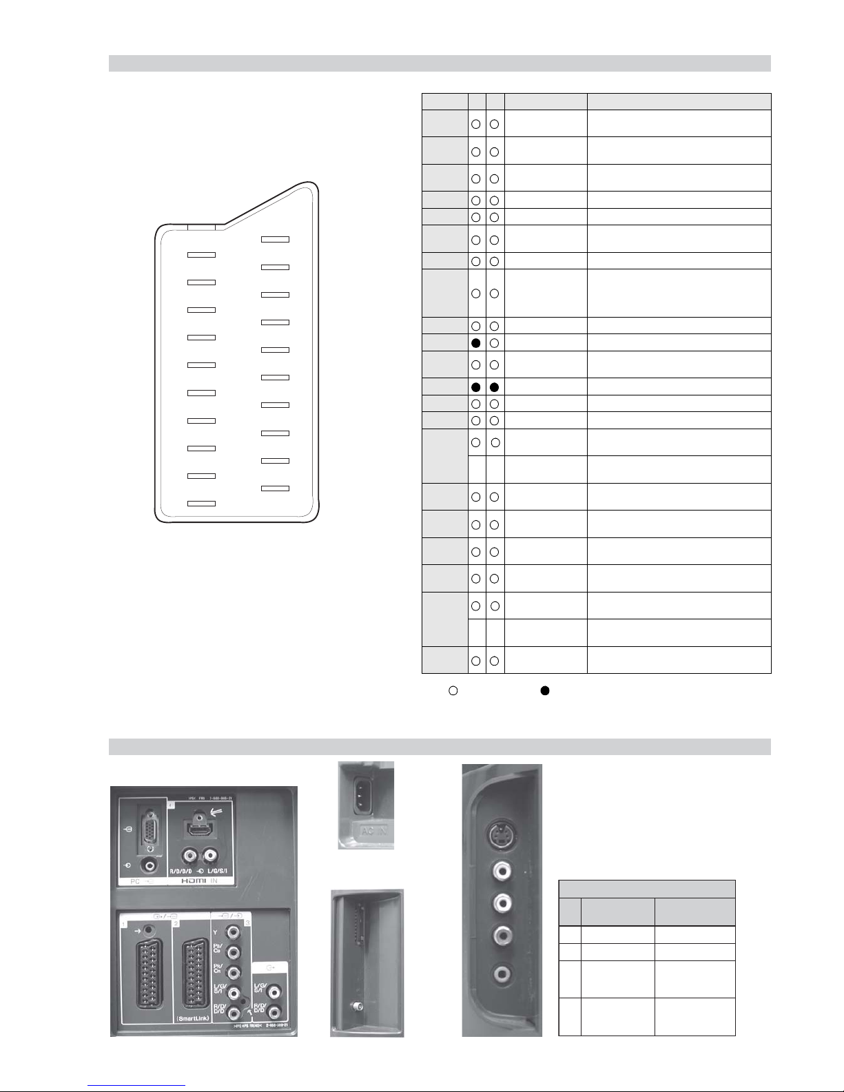
Model Name
Item
KDL-26S2000E
KDL-32S2000E
KDL-40S2000E
KDL-46S2000E
KDL-26S2000U
KDL-32S2000U
KDL-40S2000U
KDL-46S2000U
KDL-26S2010E
KDL-32S2010E
KDL-40S2010E
KDL-46S2010E
KDL-26S2010U
KDL-32S2010U
KDL-40S2010U
KDL-46S2010U
KDL-26S2020E
KDL-32S2020E
KDL-26S2020U
KDL-32S2020U
PAP OFF OFF OFF OFF OFF OFF
PAT OFF OFF OFF OFF OFF OFF
RGB Priority ON ON ON ON ON ON
Sub Woofer OFF OFF OFF OFF OFF OFF
Scart 1 ONONONONONON
Scart 2 ONONONONONON
Front in (5)ONON ONONONON
Projector OFF OFF OFF OFF OFF OFF
Norm B/G ON OFF ON OFF ON OFF
Norm I ON ON ONONONON
Norm D/K ON OFF ON OFF ON OFF
Norm AUS OFF OFF OFF OFF OFF OFF
Norm L ON OFF ON OFF ON OFF
Norm SAT OFF OFF OFF OFF OFF OFF
Norm M OFF OFF OFF OFF OFF OFF
Teletext ON ON ON ON ON ON
Nicam Stereo ON ON ON ON ON ON
- 6 -
WAX2
RM-ED005
21 pin connector
19
17
15
13
11
9
7
5
3
1
20
18
16
14
12
10
8
6
4
2
21
Rear Connection Panel Side Connection Panel
noitarugifnocniptekcosoediVS
niP
oN
langiS leveLlangiS
1dnuorG-
2dnuorG-
3tupni)langisS(Y,mho57Bd3-/+V1
V3.0.cnySevitisop
Bd01+3-
4tupni)langisS(CBd3-/+V3.0
ev
itisop,mho57
.cnyS
S-Video
socket
_ _ Red input 0.7 +/- 3dB, 75 ohms, positive
_ (S signal Chroma
Connected Not Connected (open) * at 20Hz - 20kHz
Pin No 1 2 Signal Signal level
1 Audio output B
(right)
Standard level : 0.5V rms
Output impedence : Less than 1kohm*
2
Audio input B
(right)
Standard level : 0.5V rms
Output impedence : More than 10kohm*
3
Audio output A
(left)
Standard level : 0.5V rms
Output impedence : Less than 1kohm*
4 Ground (audio)
5 Ground (blue)
6 Audio input A
(left)
Standard level : 0.5V rms
Output impedence : More than 10kohm*
7 Blue input 0.7 +/- 3dB, 75 ohms positive
8 Function select
(AV control)
High state (9.5-12V) : Part mode
Low state (0-2V) : TV mode
Input impedence : More than 10K ohms
Input capacitance : Less than 2nF
9 Ground (green)
10 AVlink
11 Green Green signal : 0.7 +/- 3dB, 75 ohms,
positive
12 Open
13 Ground (red)
14 Ground (blanking)
15
input)
0.3 +/- 3dB, 75 ohms, positive
16 Blanking input
(Ys signal)
High state (1-3V) Low state (0-0.4V)
Input impedence : 75 ohms
17 Ground (video
output)
18 Ground (video
input)
19 Video output 1V +/- 3dB, 75ohms, positive sync 0.3V
(-3+10dB)
20
Video input 1V +/- 3dB, 75ohms, positive sync 0.3V
(-3+10dB)
Video input
Y (S signal)
1V +/- 3dB, 75ohms, positive sync 0.3V
(-3+10dB)
21 Common ground
(plug, shield)
-
-
--

- 7 -
WAX2
RM-ED005
WAX2 SELF DIAGNOSTIC SOFTWARE
The identification of errors within the WAX2 chassis is triggered in one of two ways :- 1: Busy or 2: Device failure to respond to IIC. In the
event of one of these situations arising the software will first try to release the bus if busy (Failure to do so will report with a continuous
flashing LED) and then communicate with each device in turn to establish if a device is faulty. If a device is found to be faulty the relevant
device number will be displayed through the LED (Series of flashes which must be counted).
Flash Timing Example : e.g. error number 3
StBy LED
ON ON
OFF
OFF
LED Error Code
DEL
RORRE
EDOC
NOITPIRCSEDRORRE
1)3TRELACD(elbuorTegatloVylppuSV33GERNU
2)2TRELACD(elbuorTegatloVV6/V5ED,8.1DV
3)1TRELACD(
elbuorTegatloVV5LENAP,V5.01GERNU
4elbuorTthgilkcaB
5elbuorTegatloVylppuSniaM
6elbuorTegatloVdeilppArekaepS
7)
edislenapehtno.pse(erutarepmeT-edisnIniesaercnInarotinoM
8elbuorTCItnedirT
9)TORP_SC_SB/snoitacinummoC(el
buorTTTD
– 8 –
WAX2
RM-ED005
The operating instructions mentioned here are partial abstracts
from the Operating Instruction Manual. The page numbers of
the Operating Instruction Manual remain as in the manual.
SECTION 1 GENERAL
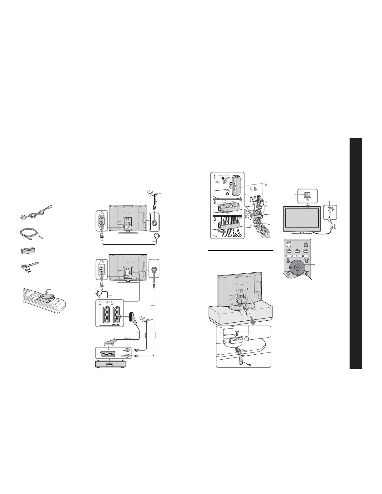
1: Checking the
accessories
Remote RM-ED005 (1)
Size AA batteries (R6 type) (2)
Mains lead (Type BF) (1)
Coaxial cable (1)
Cable holder (1)
Support belt (1) and screws (2)
To insert batteries into the remote
Notes
• Observe the correct polarity when inserting batteries.
• Dispose of batteries in an environmental ly friendly way.
Certain regions may regulate disposal of the battery .
Please consult your local authority .
• Do not use different types of batteries t ogether or mix old
and new batteries.
• Handle the remote with care. Do not dro p or step on it, or
spill liquid of any kind onto it.
• Do not place the remote in a location near a heat source, or
in a place subject to direct sunlight, or in a damp room.
2: Connecting an aerial/
VCR
Connecting an aerial only
Connecting an aerial and VCR
Coaxial cable
(supplied)
Mains lead (supplied)
Scart lead (not supplied)
RF lead
(not supplied)
VCR
Mains lead
(supplied)
3: Bundling the cables
4: Preventing the TV
from toppling over
5: Selecting the
language and country/
region
1
Connect the TV to your mains socket (220240V AC, 50Hz).
2
Press 1 on the TV (top side).
When you switch on the TV for the first time, the
Language menu appears on the screen.
When the TV is in standby mode (the
1
(standby)
indicator on the TV (front) is red), press "/1 on
the remote to switch on the TV.
2
3
1
1
2
3,4
3,4
2
Continued
– 9 –
WAX2
RM-ED005
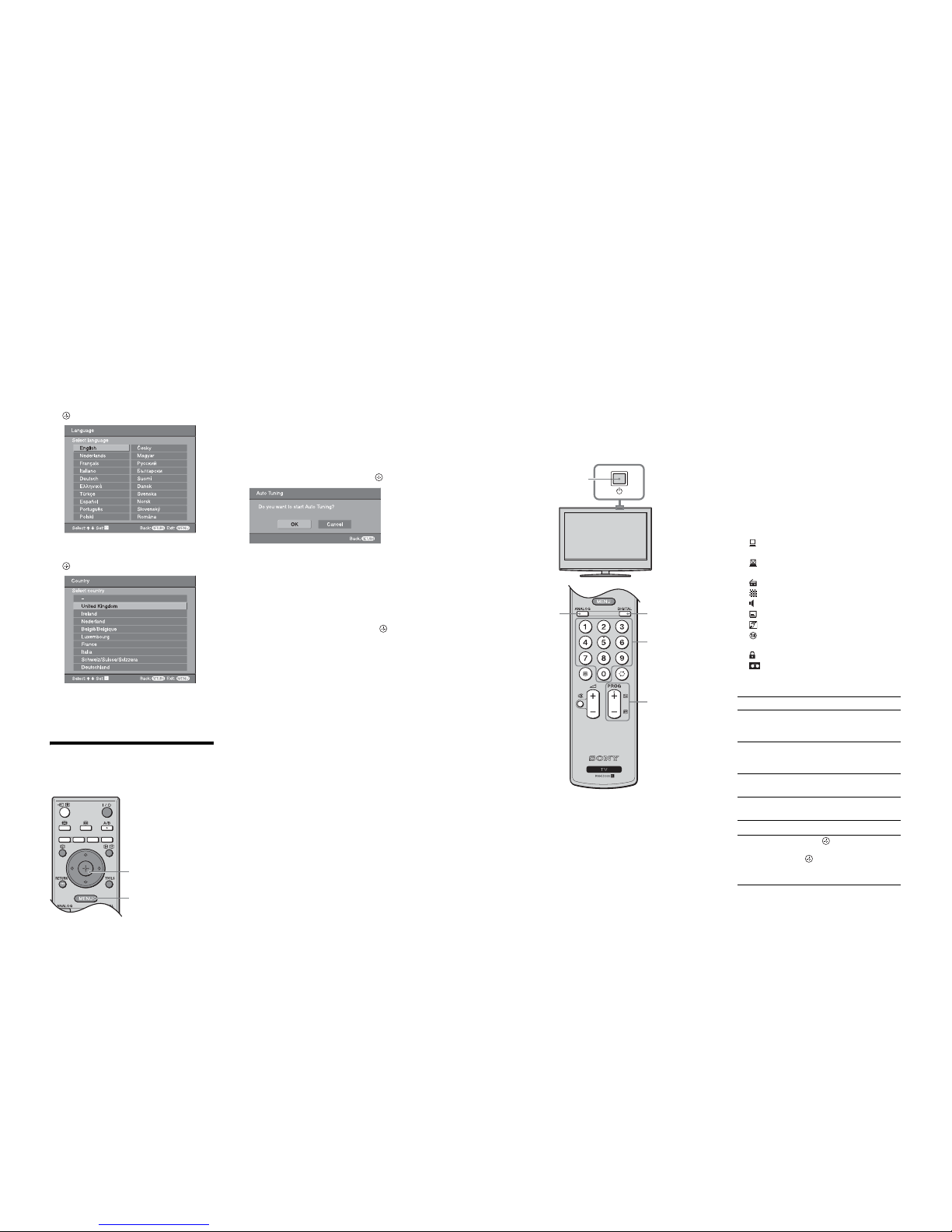
3
Press F/f to select the language
displayed on the menu screens, then press
.
4
Press F/f to select the country/region in
which you will operate the TV, then press
.
If the country/region in which you want to use the
TV does not appear in the list, select “-” instead of
a country/region.
The message confirming the TV start auto-tuning
appears on the screen, then go to “6: Auto-tuning
the TV”.
6: Auto-tuning the TV
The TV will now search for and store all availabl e TV
channels.
1
Before you start auto-tuning the TV, insert
a pre-recorded tape into the VCR
connected to the TV (page 4) and start play
back.
The video channel will be located and stored on
the TV during auto-tuning.
If no VCR is connected to the TV, this procedure
is not required. Go to step 2.
2
Press G to select “OK”, then press .
The TV starts searching for all available digital
channels, followed by all available analogue
channels. This may take some time, please be
patient and do not press any butt ons on the TV or
remote.
If a message appears for you t o confirm the aerial
connections
No digital or analo gue channels were found.
Check all the aerial connections and press to
start auto-tuning again.
3
When the Programme Sorting menu
appears on the screen, follow the steps of
“Programme Sorting” (page 29).
If you do not wish to change the order in which the
analogue channels are stored on the TV, go to step
3.
4
Press MENU to exit.
The TV has now tuned in all the available
channels.
4
2
Watching TV
1 Press 1 on the TV (top side) to switch on
the TV.
When the TV is in standby mode (t he 1 (standby)
indicator on the TV (front) is red), press "/1 on
the remote to switch on the TV.
2 Press DIGITAL to switch to digital mode or
ANALOG to switch to analogue mode.
The channels available vary depe nding on the
mode.
3 Press the number buttons or PROG +/- to
select a TV channel.
To select channel numbers 10 and above usi ng the
number buttons, enter the second and third digits
within two seconds.
To select a digital channel using the Digital
Electronic Programme Guide (EPG), see page 16.
In digital mode
An information banner appears briefly. The
following icons may be indicated on the ba nner.
Additional operations
3
1
22
3
: Interactive service is available (MHEG Digital
Text)
: Interactive service (MH EG Digital Text) is
currently disabled
: Radio service
: Scrambled/Subscription service
: Mu ltiple audio languages available
: Subtitles available
: Subtitles available for the hear ing impaired
: Recommended minimum age for current
programme (from 4 to 18 years)
: Parent al Lock
: Current programme is being recorded
To Do this
Turn off the TV
temporarily
(Standby mode)
Press "/1.
Turn on the TV
from Standby mode
without sound
Press %. Press 2 +/- to set the
volume level.
Turn off the TV
completely
Press 1 on the TV (top side).
Adjust the volume Press 2 + (increase)/
- (decrease).
Mute the sound Press %. Press again to restore.
Access the
Programme index
table (in analogue
mode only)
Press . To select an analogue
channel, press
F/f
, then press
.
To access the Input signal index
table, see page 19.
– 10 –
WAX2
RM-ED005
Checking the Digital Electronic Programme Guide
(EPG) *
1
In digital mode, press to display the
Digital Electronic Programme Guide
(EPG).
2
Perform the desired operation, as shown in
the following table.
Note
Programme information will only be displayed if the T V
station is transmitting it.
* Please note that th is function may not be available in some countries.
Digital Electronic Programme Guide (EPG)
To Do this
Turn off the EPG Press .
Move through the EPG Press
F/f/G/g
.
Watch a current programme Press while the current programme is selected.
Sort the programme information by
category – Category list
1 Press the blue button .
2 Press
F/f/G/g
to select a category. The category name is
displayed on the side.
The categories available include:
“Favourite”: Contains all the chan nels that have been stored in the
Favourite list (page 18).
“All Categories”: Contains all available channels.
“News”: Contains all news chan nels.
3 Press .
The Digital Electronic Programme Guide (EPG) now only displays the
current programmes from the category selected.
Set a programme to be recorded – Timer
REC
1 Press F/f/G/g to select the future programme you want to
record.
2 Press .
3 Press
F/f
to select “Timer REC”.
4 Press to set the TV and your VCR timers.
A symbol ap pears by that programme’s information. The
indicator on the TV (front) lights up.
Notes
• You can set VCR timer recording on the TV only for Smartlin k compatible
VCRs. If your VCR is not Smartlink compatible, a message will be displayed to
remind you to set your VCR timer.
• Once a recording has begun, you can swi tch the TV to standby mode, but do not
switch off the TV completely or the recording may be cancelled.
• If an age restriction for programmes has be en selected, a message asking for pin
code will appear on the screen. For more details refer to “Parental Lock” on
page 32.
Viewing pictures from
connected equipment
Switch on the connected equipment, the n
perform one of the following operati on.
For equipment connected t o the scart sockets using a
fully-wired 21-pin scart lead
Start playback on the connect ed equipment.
The picture from the connected equipmen t appears on
the screen.
For an auto-tuned VCR (page6)
In analogue mode, press PROG +/-, or the number
buttons, to select the video channel.
For other connected equipment
Press / repeatedly until the correct input
symbol (see below) appears on the screen.
Additional operations
Using the Tools menu
Press TOOLS to display the following options when
viewing pictures from connected equipment other
than PC.
AV1/ AV1, AV2/ AV2:
Audio/video or RGB input signal through the scart
socket / 1 or 2. appears only if an RGB
source has been connected.
AV3:
Component input signal through the Y, P
B/CB
, PR/CR
sockets / 3, and audio input signal through the
L, R sockets / 3.
AV4:
Digital audio/video signal is inp ut through the HDMI IN
4 socket. Audio input signal is analog ue only if the
equipment has been connected using the DVI and audio
out socket.
AV5/ AV5:
Video input signal through the video socket 5, and
audio input signal through the L (MO NO), R audio
sockets 5. appears only if the equipment is
connected to the S video socket 5 instead of the
video socket 5, and S video input signal is input
through the S video so cket 5.
To Do this
Return to the norma l
TV operation
Press DIGITAL or ANALOG.
Access the Input
signal index table
Press to access the Input signa l
index table. (Then, only in
analogue mode, press
g
.) To
select an input source, press
F/f
,
then press .
Options Description
Power Saving See page 27.
Picture Mode See page 21.
Sound Mode See page 23.
Auto Clock Set (in
analogue mode only)
Allows you to switch to digital
mode and obtain the time.
Sleep Timer See page 26.
i Volume See page 24.

– 11 –
WAX2
RM-ED005
Navigating through menus
“MENU” allows you to enjoy various convenient features of thi s TV. You can easily select channels or external
inputs with the remote. Also, settings for your TV can be changed easily using “MENU”.
1 Press MENU to display the menu.
2 Press
F/f
to select an option.
3 Press to confirm a selected option.
To exit the menu, press MENU.
1
2,3
Menu Description
\
Digital Favourites
(only in areas with
digital broadcasting)
Launches the Favourite list. For details about settings, see page 18.
Programme List
(only in areas with
analogue broadcasting)
Allows you to select TV programs from a list of channel labels.
• To watch the desired channel, select the channel, then press .
• To assign a label to a program, see page 29.
Analogue
(only in areas with
digital broadcasting)
Returns to the last viewed analogue channel.
Digital
(only in areas with
digital broadcasting)
Returns to the last viewed digital channel.
Digital EPG
(only in areas with
digital broadcasting)
Launches the Digital Electronic Programme Guide (EPG).
For details about settings, see page16.
External Inputs
Selects equipment connected to your TV.
• To watch the desired external input, select the input source, then
press .
• To assign a label to an external input, see page 26.
Settings
Opens the Settings menu screen where most of advanced settings and
adjustments are performed. Sele ct a menu icon, select an option and make the
desired change or adjustment using
F/f/G/g
.
For details about settings, see page21 to 32.
Picture menu
You can select the options listed below on the Picture
menu. To select options in “Settings”, see “Navigating
through menus” (page 20).
Target Inputs
Selects whether to apply settings made in the Picture menu to all inputs, or only to
the input currently being watched.
“All”: Applies settings to all inputs.
“Viewing Only”: Applies settings only to the current input.
Picture Mode
Selects the picture mode.
“Vivid”: For enhanced picture contrast and sharpness.
“Standard”: For standard picture. Recommended for home entert ainment.
“Custom”: Allows you to store your preferred settings.
Reset
Resets all picture settings except “Picture Mode” to the factory settings.
Backlight
Adjusts the brightness of the backl ight.
Contrast
Increases or decreases picture contrast.
Brightness
Brightens or darkens the picture.
Colour
Increases or decreases colour intensity.
Hue
Increases or decreases the green tones .
Tip
“Hue” can only be adjusted for an NTSC colour signal (e .g., U.S.A. video tapes).
Colour Temperature
Adjusts the whiteness of the picture.
“Cool”: Gives the white colours a blue tint.
“Neutral”: Gives the white colours a neutral tint.
“Warm1”/“Warm2”: Gives the white colours a red tint. “Warm2” g ives a redder tint
than “Warm1”.
Tip
“Warm1” and “Warm2” can only be selected when you set “Picture Mode” to “Custom”.
– 12 –
WAX2
RM-ED005
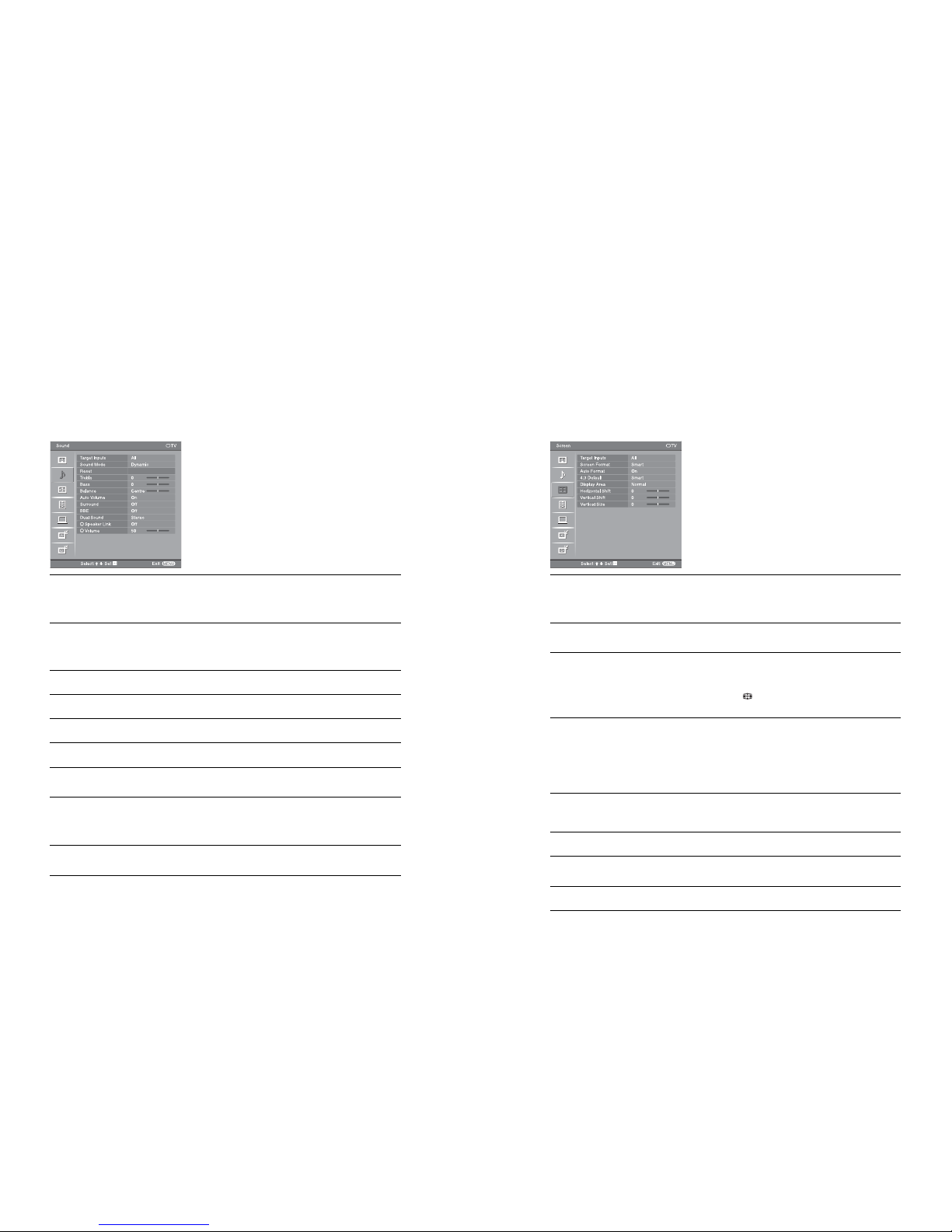
Sound menu
You can select the options listed be low on the Sound
menu. To select options in “Settings”, see “Navigating
through menus” (page 20).
Target Inputs
Selects whether to apply settings made in the Sound menu to all inputs, or only to the
input currently being watched.
“All”: Applies settings to all inputs.
“Viewing Only”: Applies settings only to the current input.
Sound Mode
Selects the sound mode.
“Dynamic”: Enhances treble and bass.
“Standard”: For standard sound. Recommended for home entert ainment.
“Custom”: Flat response. Also allows you to store your preferred settings.
Reset
Resets all the sound settings to the factory settings.
Treble
Adjusts higher-pitched sounds.
Bass
Adjusts lower-pit ched sounds.
Balance
Emphasizes left or right speaker ba lance.
Auto Volume
Keeps a constant volume level even when volu me level gaps occur (e.g., adverts tend
to be louder than programmes).
Surround
Selects the surround mode.
“TruSurround XT”: For surround sound (for stereo programmes only).
“Simulated Stereo”: Adds a surround- like effect to mono programs.
“Off”: For normal stereo or mono reception.
BBE
Gives sound more impact by compensatin g for phase effects in speakers using the
“BBE High Definition Sound System”.
Screen menu
You can select the options listed below on the Screen
menu. To select options in “Settings”, see “Navigating
through menus” (page 20).
Target Inputs
Selects whether to apply settings made in the Screen menu to all inputs, or only to
the input currently being watched.
“All”: Applies settings to all inputs.
“Viewing Only”: Applies settings only to the current input.
Screen Format
For details about the screen format, see “To change the screen mode manually to suit
the broadcast” (page 14).
Auto Format
Automatically changes the screen format according to the broadcast signal. To keep
your setting, select “Off”.
Tips
• Even if you have selected “On” or “Off ” in “Auto Format”, you can always modify the
format of the screen by pressing repeatedly.
• “Auto Format” is available for PAL and SECAM signals only.
4:3 Default
Selects the default screen mode for use with 4:3 broadcasts.
“Smart”: Displays conventional 4:3 broadcasts with an imitation wide screen effect.
“4:3”: Displays conventional 4:3 broadcasts in the correct proportions.
“Off”: Keeps the current “Screen Format” setting when the channel or inpu t is
changed.
Tip
This option is available only if “Auto Format” is set to “On”.
Display Area
Adjusts the screen area displaying the picture.
“Normal”: Displays the picture in the original size.
“–1”/“–2”: Enlarges the picture to hide the edge of the pi cture.
Horizontal Shift
Adjusts the horizontal position of the picture for each screen format.
Vertical Shift
Adjusts the vertical position of the picture when the screen format is set to Zoom or
14:9.
Vertical Size
Adjusts the vertical size of the picture.
– 13 –
WAX2
RM-ED005
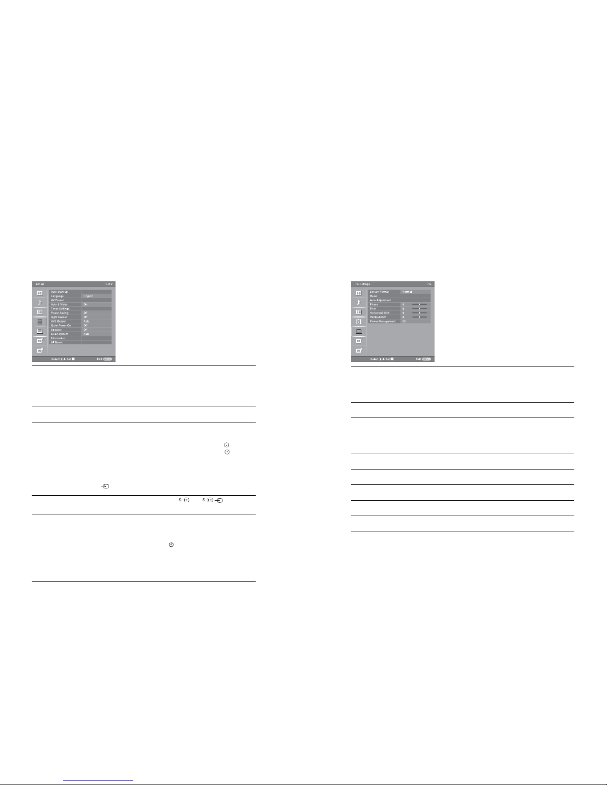
Set-up menu
You can select the options listed below on the Set-up
menu. To select options in “Settings”, see “Navigating
through menus” (page 20).
Auto Start-up
Starts the “first time operation menu” to select the language and country/region, and
tune in all available digital and analogue channels. Usually, you do not need to do
this operation because the language and country/region will have been selected and
channels already tuned when the TV was first installed (page5, 6). However, this
option allows you to repeat the proc ess (e.g., to retune the TV after moving house,
or to search for new channels that have been laun ched by broadcasters).
Language
Selects the language in which the menus are displayed.
AV Preset
Assigns a name to any equipment connected to the side and rear sockets. The name
will be displayed briefly on the screen when the equipment is selected. You can skip
an input source that is not connected to any eq uipment.
1 Press
F/f
to select the desired input source, then press .
2 Press F/f to select the desired option below, then press .
Equipment labels: Uses one of the pres et labels to assign a name to connected
equipment.
“Edit”: Creates your own label. Follow steps 2 to 4 of “Programme Labels”
(page 29).
“Skip”: Skips an input source that is not connected to any equipment when yo u press
to select the input source.
Auto S Video
Selects the input signal from S video sockets
5 when /
5 sockets are both
connected.
Timer Settings
Sets the timer to turn on/off the TV.
Sleep Timer
Sets a period of time after which the TV automatically switches itself into standby
mode.
When the Sleep Timer is activated, the (Timer) indicator on the TV (front) lights
up in orange.
Tips
• If you switch off the TV and switch it on again, “Sleep Timer” is reset to “Off”.
• “TV will soon turn off by sleep timer.” appears on t he screen one minute before the TV
switches to standby mode.
PC Settings menu
You can select the options listed be low on the PC
Settings menu. To select options in “Settings”, see
“Navigating through menus” (page 20).
Screen Format
Selects a screen mode for displaying input from your PC.
“Normal”: Displays the picture in its original size.
“Full1”: Enlarges the picture to fill the display area, keeping its original horizontalto-vertical aspect ratio.
“Full2”: Enlarges the picture to fill the display area.
Reset
Resets all the PC settings to the factory settings.
Auto Adjustment
Automatically adjusts the display position and phase of the picture when the TV
receives an input signal from the connected PC.
Tip
Auto Adjustment may not work well with certain input si gnals. In such cases, manually adjust
“Phase”, “Pitch”, “Horizontal Shift” and “Vertical Shift”.
Phase
Adjusts the phase when the screen flickers.
Pitch
Adjusts the pitch when the picture has unwan ted vertical stripes.
Horizontal Shift
Adjusts the horizontal position of the picture for each screen format.
Vertical Shift
Adjusts the vertical position of the picture for each screen format.
Power Management
Switches the TV to standby mode if no sign al is received for 30 seconds.

– 14 –
WAX2
RM-ED005
Analogue Set-up menu (Analogue mode only)
You can change/set the analogue settings using t he
Analogue Set-up menu. To select options in
“Settings”, see “Navigating throug h menus”
(page 20).
1 Digit Direct
When “1 Digit Direct” is set to “On”, you can select an analogue channel using one
preset number button (0 - 9) on the remote.
Note
When “1 Digit Direct” is set to “On” , you cannot select channel numbers 10 and abov e entering
two digits using the remote.
Auto Tuning
Tunes in all the available analogue channels.
Usually you do not need to do this operat ion because the channels are already tuned
when the TV was first installed (page 5, 6). However, this option allows you to
repeat the process (e.g., to retune the TV after moving house, or to search for new
channels that have been launched by broadcasters).
Programme Sorting
Changes the order in which the analogue channels are stored on the TV.
1 Press
F/f
to select the channel you want to move to a new position,
then press .
2 Press
F/f
to select the new position for your channel, then press .
Programme Labels
Assigns a channel name of your choice up to five letters or numbers. The name will
be displayed briefly on the screen when the chann el is selected. (Names for channels
are usually taken automatically from Analogue Text (if available).)
1 Press
F/f
to select the channel you want to name, then press .
2 Press F/f to select the desired letter or number (“-” for a blank space),
then press
g
.
If you input a wrong character
Press G/g to select the wrong character. Then, press F/f to select the correct
character.
To delete all the characters
Select “Reset”, then press
.
3 Repeat the procedure in step 2 until the name is complete.
4 Select “OK”, then press .
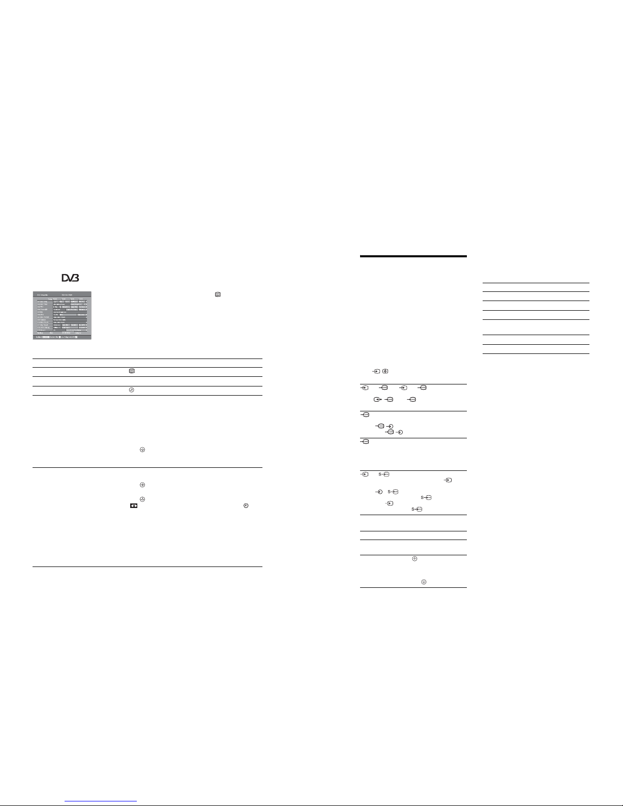
Digital Set-up menu
You can change/set the digital settings using the
Digital Set-up menu. To select options in “Settings”,
see “Navigating through menus” (page 20).
Digital Tuning
Displays the “Digital Tuning” menu.
Digital Auto Tuning
Tunes in all the available digital channels.
Usually you do not need to do this operat ion because the channels are already tuned
when the TV was first installed (page 6). However, this option allows you to repeat
the process (e.g., to retune the TV after moving house, or to se arch for new channels
that have been launched by broadcasters).
Programme List Edit
Removes any unwanted digital chann els stored on the TV, and changes the order of
the digital channels stored on the TV.
1 Press
F/f
to select the channel you want to remove or move to a new
position.
If you know the programme number ( frequency)
Press the number buttons to enter the three-digit programme number of the broadcast
you want.
2 Remove or change the order of the digital channels as follows:
To remove the digital channe l
Press . A message that confirms whether the selected digital channel is to be
deleted appears. Press
G
to select “Yes”, then press .
To change the order of the digital channels
Press g, then press F/f to select the new position for the channel and press G.
Repeat the procedure in steps 1 and 2 to move other channels if required.
3 Press RETURN.
Digital Manual Tuning
Tunes the digital channels manua lly.
1 Press the number button to select the channel number you want to
manually tune, then press
F/f
to tune the channel.
2 When the available channels are found, press
F/f
to select the channel
you want to store, then pres s .
3 Press
F/f
to select the programme number where you want to store the
new channel, then press .
Repeat the procedure above to tune other channels manua lly.
– 15 –
WAX2
RM-ED005
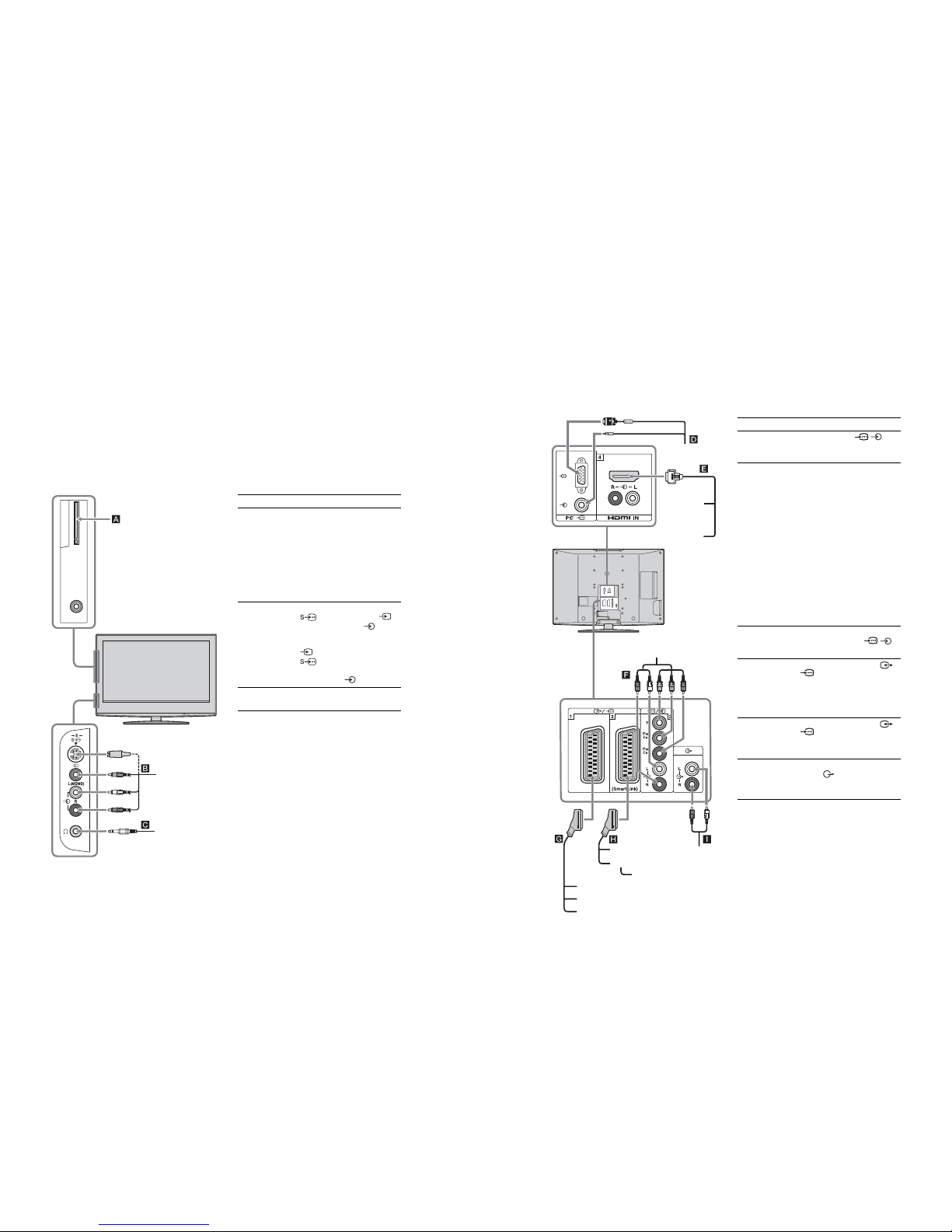
Connecting optional equipment
You can connect a wide range of optio nal equipment to your TV. Connecting cables are not supplied.
Connecting to the TV (side)
Headphones
S VHS/Hi8/DVC
camcorder
To connect Do this
Conditional Access
Module (CAM) A
To use Pay Per View services.
For details, refer to the instruction
manual supplied with your CAM.
To use the CAM, remove the
rubber cover from the CAM slot.
Switch off the TV when inserting
your CAM into the CAM slot.
When you do not use the CAM, we
recommend that you replace the
cover on the CAM slot.
S VHS/Hi8/DVC
camcorder B
Connect to the S video socket
5 or the video socket 5,
and the audio sockets 5. To
avoid picture noise, do not connect
the camcorder to the video socket
5 and the S video socket
5 at the same time. If you
connect mono equipment, conne ct
to the L socket 5.
Headphones C Connect to the i socket to listen to
sound from the TV on headph ones.
Connecting to the TV (rear)
DVD player
with component output
DVD player
Decoder
DVD recorder
VCR
Hi-Fi
Video game equipment
DVD player
Digital satellite receiver
PC
Decoder
To connect Do this
PC D Connect to the PC /
sockets. It is recommended to use
a PC cable with ferrites.
Digital satellite
receiver or DVD
player E
Connect to the HDMI IN 4 socket
if the equipment has a HDMI
socket. The digital video and a udio
signals are input from the
equipment. If the equipment has a
DVI socket, connect the DVI
socket to the HDMI IN 4 socket
through a DVI - HDMI adaptor
interface (not supplied), and
connect the equipment’s audio out
sockets to the audio in HD MI IN 4
sockets.
Note
The HDMI sockets only support the
following video inputs: 480i , 480p,
576i, 576p, 720p and 1080i. T o
connect a PC, please use the P C input
socket.
DVD player with
component output
F
Connect to the component sockets
and the audio sockets / 3.
Video game
equipment, DVD
player or decoder
G
Connect to the scart socket /
1. When you connect the
decoder, the scrambled signal from
the TV tuner is output to the
decoder, then the unscrambled
signal is output from the decode r.
DVD recorder or
VCR that supports
SmartLink H
Connect to the scart socket /
2. SmartLink is a direct l ink
between the TV and a VCR/DVD
recorder.
Hi-Fi audio
equipment I
Connect to the audio output
sockets to listen to the sound
from the TV on Hi-Fi audio
equipment.

– 16 –
WAX2
RM-ED005
Specifications
Display Unit
Power Requirements:
220–240 V AC, 50 Hz
Screen Size:
KDL-46S2000/KDL-46S2010:
46 inches (Approx. 116.9 cm measured diagonally)
KDL-40S2000/KDL-40S2010:
40 inches (Approx. 101.6 cm measured diagonally)
KDL-32S2000/KDL-32S2010:
32 inches (Approx. 80.1 cm measured diagonally)
KDL-26S2000/KDL-26S2010:
26 inches (Approx. 66.1 cm measured diagonally)
Display Resolution:
1,366 dots (horizontal) × 768 lines (vertical)
Power Consumption:
KDL-46S2000/KDL-46S2010: 250 W
KDL-40S2000/KDL-40S2010: 180 W
KDL-32S2000/KDL-32S2010: 125 W
KDL-26S2000/KDL-26S2010: 100 W
Standby Power Consumption:
0.3 W
Dimensions (w × h × d):
KDL-46S2000/KDL-46S2010:
Approx. 1,120 × 805 × 334 mm (with stand)
Approx. 1,120 × 755 × 116 mm (without stand)
KDL-40S2000/KDL-40S2010:
Approx. 988 × 716 × 334 mm (with stand)
Approx. 988 × 664 × 103 mm (without stand)
KDL-32S2000/KDL-32S2010:
Approx. 792 × 593 × 219 mm (with stand)
Approx. 792 × 546 × 99 mm (without stand)
KDL-26S2000/KDL-26S2010:
Approx. 658 × 516 × 219 mm (with stand)
Approx. 658 × 470 × 94 mm (without stand)
Mass:
KDL-46S2000/KDL-46S2010:
Approx. 34 kg (with stand)
Approx. 28 kg (without stand)
KDL-40S2000/KDL-40S2010:
Approx. 27 kg (with stand)
Approx. 21 kg (without stand)
KDL-32S2000/KDL-32S2010:
Approx. 17 kg (with stand)
Approx. 15 kg (without stand)
KDL-26S2000/KDL-26S2010:
Approx. 13 kg (with stand)
Approx. 11 k
g (without stand)
Panel System
LCD (Liquid Crystal Display) Panel
TV System
Analogue: Depending on your country/region selection:
B/G/H, D/K, L, I
Digital: DVB-T
Colour/Video System
Analogue: PAL, SECAM
NTSC 3.58, 4.43 (only Video In)
Digital: MPEG-2 MP@ML
Aerial
75 ohm external terminal for VHF/UHF
Channel Coverage
Analogue: VHF: E2–E12
UHF: E21–E69
CATV: S1–S20
HYPER: S21–S41
D/K: R1–R12, R21–R69
L: F2–F10, B–Q, F21–F69
I: UHF B21–B69
Digital: VHF/UHF
Terminals
/1
21-pin Scart connector (CENELEC standard) including
audio/video input, RGB input, and TV audio/video
output.
/ 2 (SmartLink)
21-pin Scart connector (CENELEC standard) including
audio/video input, RGB input, selectable audio/video
output, and SmartLink interface.
3
Supported formats: 1080i, 720p, 576p, 576i, 480p, 480i
Y: 1 Vp-p, 75 ohms, 0.3V negative sync
P
B/CB
: 0.7 Vp-p, 75 ohms
P
R/CR
: 0.7 Vp-p, 75 ohms
3
Audio input (phono jacks)
500 mVrms
Impedance: 47 kilo ohms
HDMI IN 4
Video: 1080i, 720p, 576p, 576i, 480p, 480i
Audio: Two channel linear PCM
32, 44.1 and 48 kHz, 16, 20 and 24 bits,
or analogue audio input (phono jacks)
5 S video input (4-pin mini DIN)
5 Video input (phono jack)
5Audio input (phono jacks)
Audio output (Left/Right) (phono jacks)
PC PC Input (15 Dsub) (see page 37)
G: 0.7 Vp-p, 75 ohms, non Sync on Green
B: 0.7 Vp-p, 75 ohms, non Sync on Green
R: 0.7 Vp-p, 75 ohms, non Sync on Green
HD: 1-5 Vp-p
VD: 1-5 Vp-p
PC audio input (minijack)
i Headphones jack
CAM (Conditional Access Module) slot
Additional Information
Sound Output
10 W + 10 W
Supplied Accessories
Refer to “1: Checking the accessories” on page4.
Optional Accessories
• Wall-Mount Bracket
SU-WL51 (for KDL-46S2000/KDL-46S2010/
KDL-40S2000/KDL-40S2010)
SU-WL31 (for KDL-32S2000/KDL-32S2010/
KDL-26S2000/KDL-26S2010)
Design and specifications are subject to change
without notice.
PC Input Signal Reference Chart
• This TV’s PC input does not support Sync on Green or Composite Sync.
• This TV’s PC input does not support interlaced signals.
• This TV’s PC input supports the boldfaced signals in the above chart with a 60 Hz vertical frequency.
• For the best picture quality, it is recommended to use signals with a 60 Hz vertical frequency from a personal computer. In plug
and play, signals with a 60 Hz vertical frequency will be selected automatically.
Signals Horizontal (Pixel) Vertical (Line)
Horizontal
frequency
(kHz)
Vert ical
frequency (Hz)
Standard
VGA 640 480 31.5 60 VGA
640 480 37.5 75 VESA
720 400 31.5 70 VGA-T
SVGA 800 600 37.9 60 VESA Guidelines
800 600 46.9 75 VESA
XGA 1024 768 48.4 60 VESA Guidelines
1024 768 56.5 70 VESA
1024 768 60 75 VESA
WXGA 1280 768 47.4 60 VESA
1280 768 47.8 60 VESA
1360 768 47.7 60 VESA

– 17 –
WAX2
RM-ED005
Troubleshooting
Check whether the 1 (standby) indicat or is flashing in red.
When it is flashing
The self-diagnosis function is activated.
1 Measure how long the 1 (standby) indicator flashes and stops flashing.
For example, the indicator flashes for two seconds, stops flashing for one sec ond, and flashes for two seconds.
2 Press 1 on the TV (top side) to switch it off, disconnect the mains lead, and inform your dealer or
Sony service centre of how the indicator flashes (duration and interval).
When it is not flashing
1 Check the items in the tables below.
2 If the problem still persists, have your TV serviced by qualified service personnel.
Picture
Problem Cause/Remedy
No picture (screen is dark) an d
no sound
• Check the aerial connection.
• Connect the TV to the mains, and press 1 on the TV (top side).
• If the 1 (standby) indicator lights up in red, press "/1.
No picture or no menu
information from equipment
connected to the scar t
connector
• Check that the optional equipment is on and press / repeatedly until
the correct input symbol is displayed on the screen.
• Check the connection between the optional equipment and the TV.
Double images or ghosting
• Check ae rial/cable connections.
• Check the aerial location and direction.
Only snow and noise appear
on the screen
• Che ck if the aerial is broken or bent.
• Check i f the aerial has reached the end of its serviceable life (three to five
years in normal use, one to two years at the seaside).
Distorted picture (dotted lines
or stripes)
• Keep the TV away from electrical noise sources such as cars, motorcycles,
hair-dryers or optical equipment.
• When installing optional equipment, leave some space between the optional
equipment and the TV.
• Make sure that the aerial is connected using the supplied c oaxial cable.
• Keep the aerial cabl e away from other connecting cables.
Picture noise when viewing a
TV channel
• Select “Manual Programme Preset” in the “Analogue Set-up” menu and
adjust “AFT” (Automatic Fine Tuning) to obtain better picture reception
(page 30).
Some tiny black points and/or
bright points on the screen
• The p icture of a display unit is composed of pixels. Tiny black points and/or
bright points (pixels) on the screen do not indicate a malfunction.
No colour on programmes
• Select “Rese t” in the “Picture” menu to return to the factory settings
(page 21).
No colour or irre gular colour
when viewing a signal from the
Y, PB/CB, PR/CR jacks of 3
• Che ck the connection of the Y, PB/CB, PR/CR jacks of 3.
• Make sure that t he Y, PB/CB, PR/CR jacks of 3 are firmly seated in their
respective sockets.
Sound
Problem Cause/Remedy
No sound, but good picture
• Press 2 +/– or % (Mute).
• Check t hat “Speaker” is set to “On” in the “Set-up” menu (page 27).
Noisy sound
• See the “Pi cture noise” causes/remedies on page 38.
Channels
Problem Cause/Remedy
The desired channel cannot be
selected
• Switc h between digital and analogue mode and select the desired di gital/
analogue channel.
Some channels are blank
• Scramb led/Subscription only channel. Subscribe to the Pay Per View
service.
• Cha nnel is used only for data (no picture or sound).
• Contact the broadcaster for transmission details.
Digital channel is not displayed
• Contact a local installer to find out if digital transmissions are provided in
your area.
• Upgrad e to a higher gain aerial.
General
Problem Cause/Remedy
The TV turns off automatically
(the TV enters standby mode)
• Check if the “Sleep Timer” is activated, or confirm the “Duration” setting of
“On Timer” (page 26).
• If no signal i s received and no operation is performed in the TV mode for
10 minutes, the TV automatically switches to standby mode.
The TV turns on automatically
• Check i f the “On Timer” is activated (page 27).
Some input sources cannot be
selected
• Select “AV Preset” in the “Set-up” menu and cancel “Skip” of the input
source (page 26).
The remote does not function
• Replace the b atteries.
– 18 –
WAX2
RM-ED005
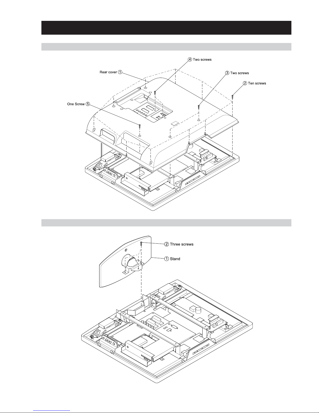
SECTION 2 DISASSEMBLY
2-2. STAND REMOVAL
2-1. REAR COVER REMOVAL
– 19 –
WAX2
RM-ED005
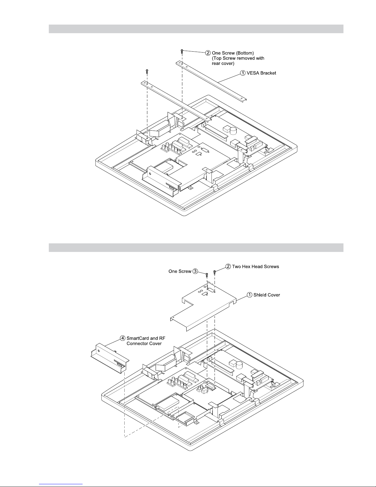
2-3. VESA BRACKET REMOVAL
2-4. SHIELD COVER REMOVAL
– 20 –
WAX2
RM-ED005
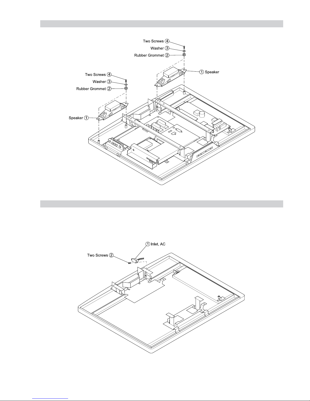
2-5. SPEAKER REMOVAL
2-6. AC INLET REMOVAL
– 21 –
WAX2
RM-ED005
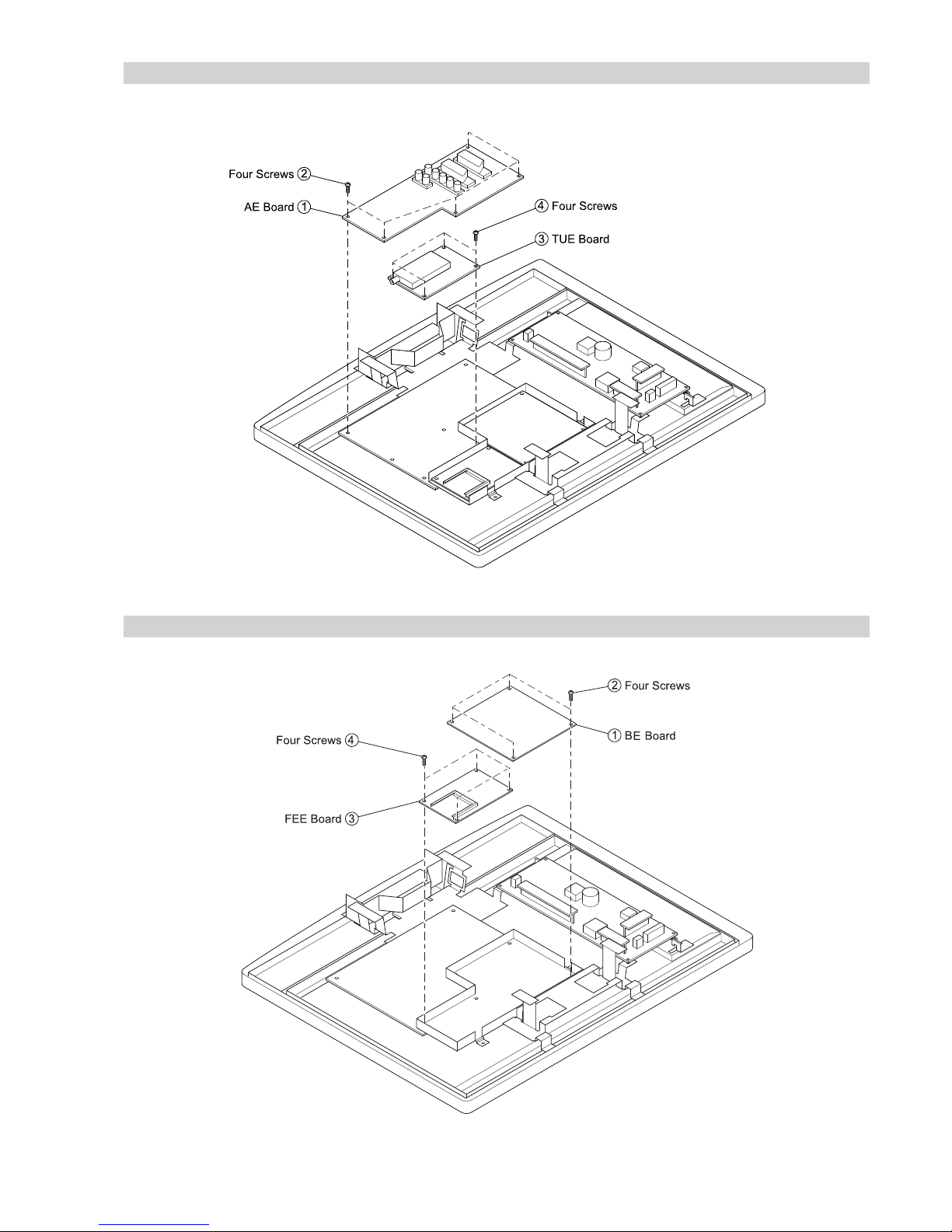
2-7. AE and TUE BOARD REMOVAL
2-8. BE and FEE BOARD REMOVAL

– 22 –
WAX2
RM-ED005
2-9. G1 or G2 BOARD REMOVAL
2-10. H1E BOARD REMOVAL

– 23 –
WAX2
RM-ED005
2-11. H2E or H46E BOARD REMOVAL
2-12. H3E BOARD REMOVAL
H2E or H46E Board
H2E or H46E Board
H2E or H46E Board Bracket
H2E or H46E Board Bracket
– 24 –
WAX2
RM-ED005
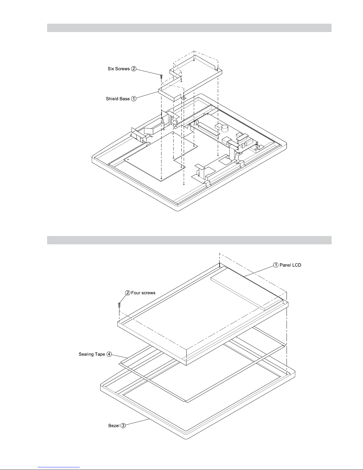
2-13. SHIELD BASE REMOVAL
2-14. LCD PANEL REMOVAL
- 25 -
WAX2
RM-ED005
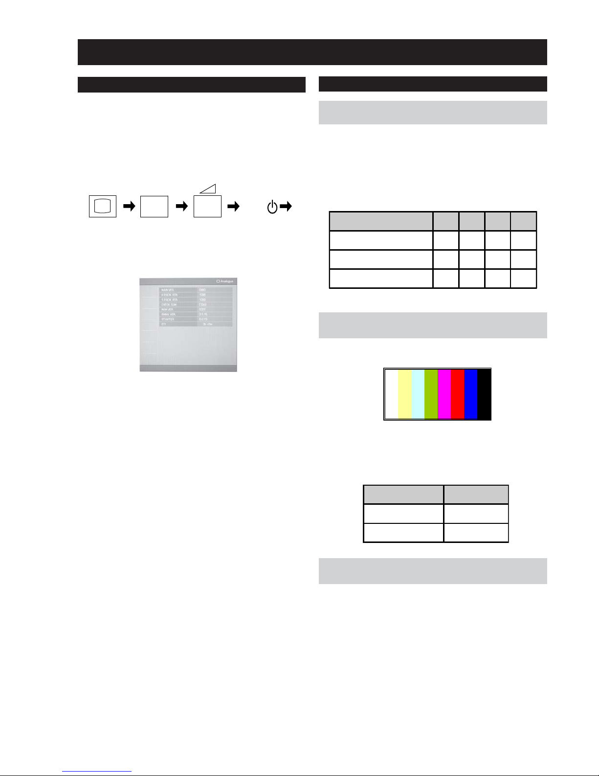
AD-Adjust RF Spec Spec.
Reference register name
S-REG: APL_LUMA TARGET_Y_RF±2
Service adjustments to this model can be performed using the
supplied remote Commander RM-ED005.
3. The following menu will then appear on the screen.
4. Move to the relevant command using the up or down arrow
buttons on the remote commander.
5. Press the right arrow button to enter into the required menu item.
6. Press the ‘Menu’ button on the remote commander to quit the
Service Mode when all adjustments have been completed.
Note :
• After carrying out the service adjustments, to prevent the
customer accessing the ‘Service Menu’ switch the TV set OFF
and then ON.
1. Turn on the power to the TV set and enter into the stand-by
mode.
2. Press the following sequence of buttons on the Remote
Commander.
SECTION 3 SET-UP ADJUSTMENTS
3-1. How to enter Service Mode
i+
5
+
(ON SCREEN (DIGIT 5) (VOLUME +) (TV)
DISPLAY)
I/
TV
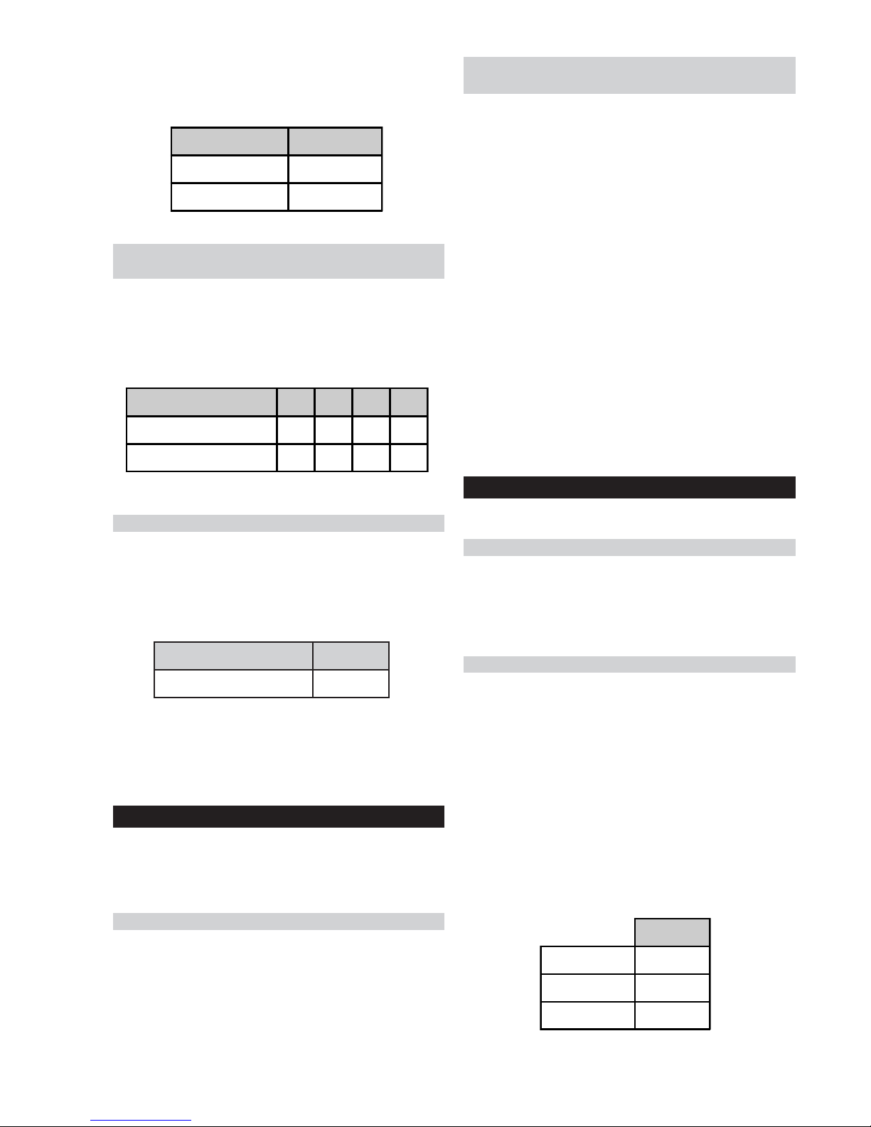
3-2-2.
Y signal calibration1 adjustment for
terrestrial analog.
1. Input PAL colour bar 75%Y, 75%C via terrestrial input.
2. Send ECS_ADJUST_TCD3_CONT_RF command.
3. Read the value of S-REG:APL_LUMA via ECS. Confirming that
the value is within spec of the table below.
3-2-3.
Set up of C signal calibration1 adjustment
for terrestrial analog.
1. Input PAL colour bar 75%Y, 75%C via terrestrial input.
2. Send ECS_ADJUST_LEVEL_SETTING_INIT command.
3. Ensure noise reduction NR=3 (High), GAMMA_EN=0,
P4_CVD2_85=0.
3-2-1.
Set up of AD calibration1 adjustment for
terrestrial analog.
The following adjustments are done via ECS.
1. Send ECS_ADJUST_LEVEL_SETTING_INIT command.
2. Ensure noise reduction NR=3 (High), GAMMA_EN=0,
P4_CVD2_85=0.
3. Set the following registration items.
3-2. Signal Level Adjustment
Screen Size 26" 32" 40" 46"
TARGET_Y_RF(PAL) 165 165 165 165
ADJ_COLOR_Y_ATT(PAL) 128 128 128 128
ADJ_COLOR_PAL(PAL) 3 3 3 3
㧜
㧞㧟㧠㧡㧢㧣

- 26 -
WAX2
RM-ED005
3-2-4.
C signal calibration1 adjustment for
terrestrial analog.
1. Send ECS_ADJUST_TCD3_HUE_RF command.
2. Read S-REG: READ_BACK_B00 via ECS. (READ_AREA=0).
3. Read S-REG: READ_BACK_B01 via ECS. (READ_AREA=6).
4. Confirm that 8 bits of MSB of item number 2) and 3) are within
spec of the table below.
metIecnerefeR .cepS
eulavecnereffid*0B_KCAB_DAER2±
3-2-5.
Set up of AD calibration1 adjustment for
video.
1. Send ECS_ADJUST_LEVEL_SETTING_INIT command.
2. Ensure noise reduction NR=1 (Low), GAMMA_EN=0,
P4_CVD2_85=0.
3. Set the following registration items.
3-2-6.
Y signal calibration1 adjustment for video.
1. Input PAL colour bar 75%Y, 75%C via AV1 input.
2. Send ECS_ADJUST_TCD3_CONT_V command.
3. Read the value of S-REG:APL_LUMA via ECS. Confirming that
the value is within spec of the table below.
Screen Size 26" 32" 40" 46"
TARGET_Y_V(PAL) 165 165 165 165
ADJ_COLOR_Y_ATT(PAL) 128 128 128 128
ADJ_COLOR_PAL(PAL) 3 3 3 3
㧜
㧞㧟
㧠㧡㧢㧣
㧠㧡㧢㧣
AD-Adjust Video Spec Spec.
Reference register name
S-REG: APL_LUMA TARGET_Y_V±2
5. Switch the TV set OFF and then ON again to retain adjustment
values.
3-2-7.
Set up of C signal calibration1 adjustment
for video.
1. Input PAL colour bar 75%Y, 75%C via AV1 input.
2. Send ECS_ADJUST_LEVEL_SETTING_INIT command.
3. Ensure noise reduction NR=1 (Low), GAMMA_EN=0,
P4_CVD2_85=0.
4. Set the following registration items.
Screen Size 26" 32" 40" 46"
ADJ_COLOR_Y_ATT(PAL) 128 128 128 128
ADJ_COLOR_PAL(PAL) 3 3 3 3
3-2-8.
C signal calibration1 adjustment for video.
1. Send ECS_ADJUST_TCD3_HUE_V command.
2. Read S-REG: READ_BACK_B00 via ECS. (READ_AREA=0).
3. Read S-REG: READ_BACK_B01 via ECS. (READ_AREA=6).
4. Confirm that 8 bits of MSB of item number 2) and 3) are within
spec of the table below.
metIecnerefeR .cepS
eulavecnereffid*0B_KCAB_DAER2±
5. Read S-REG: TCD3_SATURATION via ECS.
6. Switch the TV set OFF and then ON again to retain adjustment
values.
Screen Size 26" 32" 40" 46"
TARGET_Y_V(SECAM) 165 165 165 165
ADJ_COLOR_Y_ATT(SECAM) 128 128 128 128
ADJ_COLOR_PAL(SECAM) 2 2 2 2
3-2-9.
Set up of AD calibration2 adjustment for
video.
1. Send ECS_ADJUST_LEVEL_SETTING_INIT command.
2. Ensure noise reduction NR=1 (Low), GAMMA_EN=0,
P4_CVD2_85=0.
3. Set the following registration items.
㧜
㧞㧟㧠㧡㧢㧣
3-2-10.
Y signal calibration2 adjustment for video.
1. Input SECAM colour bar 75%Y, 75%C via AV1 input.
- 27 -
WAX2
RM-ED005
1. Ensure TEST_PATTEN_ON=1.
2. Ensure TEST_G_LEVEL=204.
3. Ensure TEST_R_LEVEL=0.
4. Ensure TEST_B_LEVEL=0.
5. Measure brightness A.
6. Ensure TEST_G_LEVEL=102.
7. Ensure TEST_R_LEVEL=0.
8. Ensure TEST_B_LEVEL=0.
9. Measure brightness B.
10. Set up G_GAMMA_OFST_01=brightness B/brightness
A*10000. The result is written to G_GAMMA_OFST_01.
11. Send Gamma_Tbl_Search_1 command.
12. Ensure TEST_G_LEVEL=153.
3-3-2. Set up Trident internal SG and brightness
measurement
13. Ensure TEST_R_LEVEL=0.
14. Ensure TEST_B_LEVEL=0.
15. Measure brightness C.
16. Set up G_GAMMA_OFST_02=brightness C/brightness
A*10000. The result is written to G_GAMMA_OFST_02.
17. Send Gamma_Tbl_Search_2 command.
18. Save set up value in NVM in register G_GAM_IDX_OFST.
20IRE
TEST_R_LEVEL 51
TEST_G_LEVEL 51
TEST_B_LEVEL 51
3-4. White Balance Adjustment
The following adjustments are done via ECS.
3-4-1. Set up mode for White Balance Adjustment
1. Send ECS_ADJUST_LEVEL_SETTING_INIT command.
2. Ensure COL_MATRIX_INDEX=15.
3. Ensure hreg p1_d_p_26=0 and hreg p1_d_p_28=0.
4. Ensure DYNAMIC_EN=0.
3-4-2. White Balance of colour temperature “High”
1. Set up COLOR_TEMP=0.
2. Set up GAMMA_OFF=15.
3. R_GAMMA_OFST_01=128
R_GAMMA_OFST_02=128
R_GAMMA_OFST_03=128
R_GAMMA_OFST_04=128
B_GAMMA_OFST_01=128
B_GAMMA_OFST_02=128
B_GAMMA_OFST_03=128
Set up B_GAMMA_OFST_04=128.
4. Set up “Wait”.
5. Set up the correct values for 20IRE for TEST_R_LEVEL,
TEST_G_LEVEL and TEST_B_LEVEL.
2. Send ECS_ADJUST_TCD3_CONT_V command.
3. Read the value of S-REG:APL_LUMA via ECS. Confirming that
the value is within spec of the table below.
AD-Adjust Video Spec Spec.
Reference register name
S-REG: APL_LUMA TARGET_Y_V±2
3-2-11.
Set up of C signal calibration2 adjustment
for video.
1. Input SECAM colour bar 75%Y, 75%C via AV1 input.
2. Send ECS_ADJUST_LEVEL_SETTING_INIT command.
3. Ensure noise reduction NR=1 (Low), GAMMA_EN=0,
P4_CVD2_85=0.
4. Set the following registration items.
Screen Size 26" 32" 40" 46"
ADJ_COLOR_Y_ATT(SECAM) 128 128 128 128
ADJ_COLOR_PAL(SECAM) 2 2 2 2
3-2-12.
C signal calibration2 adjustment for video.
1. Send ECS_ADJUST_TCD3_HUE_V command.
2. Read S-REG: READ_BACK_B00 via ECS. (READ_AREA=0).
3. Read S-REG: READ_BACK_B01 via ECS. (READ_AREA=6).
4. Confirm that 8 bits of MSB of item number 2) and 3) are within
spec of the table below.
metIecnerefeR .cepS
eulavecnereffid*0B_KCAB_DAER2±
5. Read S-REG: TCD3_SATURATION via ECS.
6. Switch the TV set OFF and then ON again to retain adjustment
values.
3-3. Gamma Adjustment
The following adjustments are done via ECS.
Note: Before Gamma adjustment can begin the set needs 1 hour aging.
1. Send ECS_ADJUST_LEVEL_SETTING_INIT command.
2. Ensure COL_MATRIX_INDEX=15.
3. Ensure hreg p1_d_p_26=0 and hreg p1_d_p_28=0.
4. Ensure G_GAMMA_IDX_OFST=15.
5. Ensure DYNAMIC_EN=0.
3-3-1. Set up mode for Gamma Adjustment
- 28 -
WAX2
RM-ED005
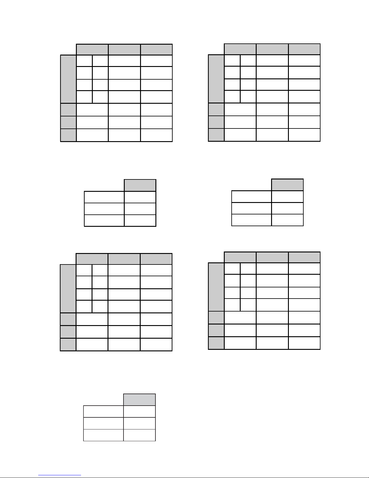
(*1) If adjustment results exceed the tolerance please extend
the tolerance to 0.6JND.
80IRE
TEST_R_LEVEL 204
TEST_G_LEVEL 204
TEST_B_LEVEL 204
40IRE
TEST_R_LEVEL 102
TEST_G_LEVEL 102
TEST_B_LEVEL 102
X Y Tol er anc e
26"
20IRE 0.263 0.274 0.5JND(*1)
40IRE 0.268 0.273 0.5JND(*1)
60IRE 0.265 0.272 0.5JND(*1)
80IRE 0.265 0.272 0.5JND(*1)
32"
0.27 0.271 0.5JND
40" 0.272 0.272 0.5JND
46" 0.273 0.274 0.5JND
6. Adjust R_GAMMA_OFST_01 and B_GAMMA_OFST_01
chroma values so that they are within tolerance in the table below.
10. Adjust R_GAMMA_OFST_03 and B_GAMMA_OFST_03
chroma values so that they are within tolerance in the table below.
ERI06
LEVEL_R_TSET351
LEVEL_G_TSET351
LEVEL_B_TSET351
7. Set up the correct values for 40IRE for TEST_R_LEVEL,
TEST_G_LEVEL and TEST_B_LEVEL.
8. Adjust R_GAMMA_OFST_02 and B_GAMMA_OFST_02
chroma values so that they are within tolerance in the table below.
9. Set up the correct values for 60IRE for TEST_R_LEVEL,
TEST_G_LEVEL and TEST_B_LEVEL.
11. Set up the correct values for 80IRE for TEST_R_LEVEL,
TEST_G_LEVEL and TEST_B_LEVEL.
12. Adjust R_GAMMA_OFST_04 and B_GAMMA_OFST_04
chroma values so that they are within tolerance in the table below.
13. Write R_GAMMA_OFST_01~R_GAMMA_OFST_04 and
B_GAMMA_OFST_01~B_GAMMA_OFST_04 in the NVM.
14. Write R_GAMMA_OFST_04~R_GAMMA_OFST_05 and
B_GAMMA_OFST_04~B_GAMMA_OFST_05 in the NVM.
15. Set up TEST_PATTEN_ON=0.
16. Set up COL_MATRIX_INDEX=30.
17. Set up hreg_p1_d_p_26=3.
18. Set up hreg_p1_d_p_28=3.
19. Set up DYNAMIC_EN=0xffff
20. Set up COLOR_TEMP=1.
21. Write the correct values for R_DRV, B_DRV, R_BKG and B_BKG
from the table below.
X Y Tol er an ce
26"
20IRE 0.263 0.274 0.5JND(*1)
40IRE 0.268 0.273 0.5JND(*1)
60IRE 0.265 0.272 0.5JND(*1)
80IRE 0.265 0.272 0.5JND(*1)
32" 0.27 0.271 0.5JND
40"
0.272 0.272 0.5JND
46"
0.273 0.274 0.5JND
X Y Tol er anc e
26"
20IRE 0.263 0.274 0.5JND(*1)
40IRE 0.268 0.273 0.5JND(*1)
60IRE 0.265 0.272 0.5JND(*1)
80IRE 0.265 0.272 0.5JND(*1)
32"
0.27 0.271 0.5JND
40" 0.272 0.272 0.5JND
46" 0.273 0.274 0.5JND
X Y Tol er anc e
26"
20IRE 0.263 0.274 0.5JND(*1)
40IRE 0.268 0.273 0.5JND(*1)
60IRE 0.265 0.272 0.5JND(*1)
80IRE 0.265 0.272 0.5JND(*1)
32"
0.27 0.271 0.5JND
40" 0.272 0.272 0.5JND
46" 0.273 0.274 0.5JND
(*1) If adjustment results exceed the tolerance please extend
the tolerance to 0.6JND.
(*1) If adjustment results exceed the tolerance please extend
the tolerance to 0.6JND.
(*1) If adjustment results exceed the tolerance please extend
the tolerance to 0.6JND.
- 29 -
WAX2
RM-ED005
3-5. Panel Replacement
When replacing the panel please reset the gamma and white balance
before performing W/B (See page 27) for new panel.
3-6. Board Replacement
3-6-1. AE Board Replacement
When replacing the ‘AE’ board please readjust the AD (See page 25)
and readjust the W/B (See page 27).
3-6-2. BE Board Replacement
When replacing the ‘BE’ board please readjust the AD (See page 25)
and readjust the W/B (See page 27).
Note :
In the event of a ‘BE’ board being re-used in service please
ensure that the Serial number is cleared in the NVM.
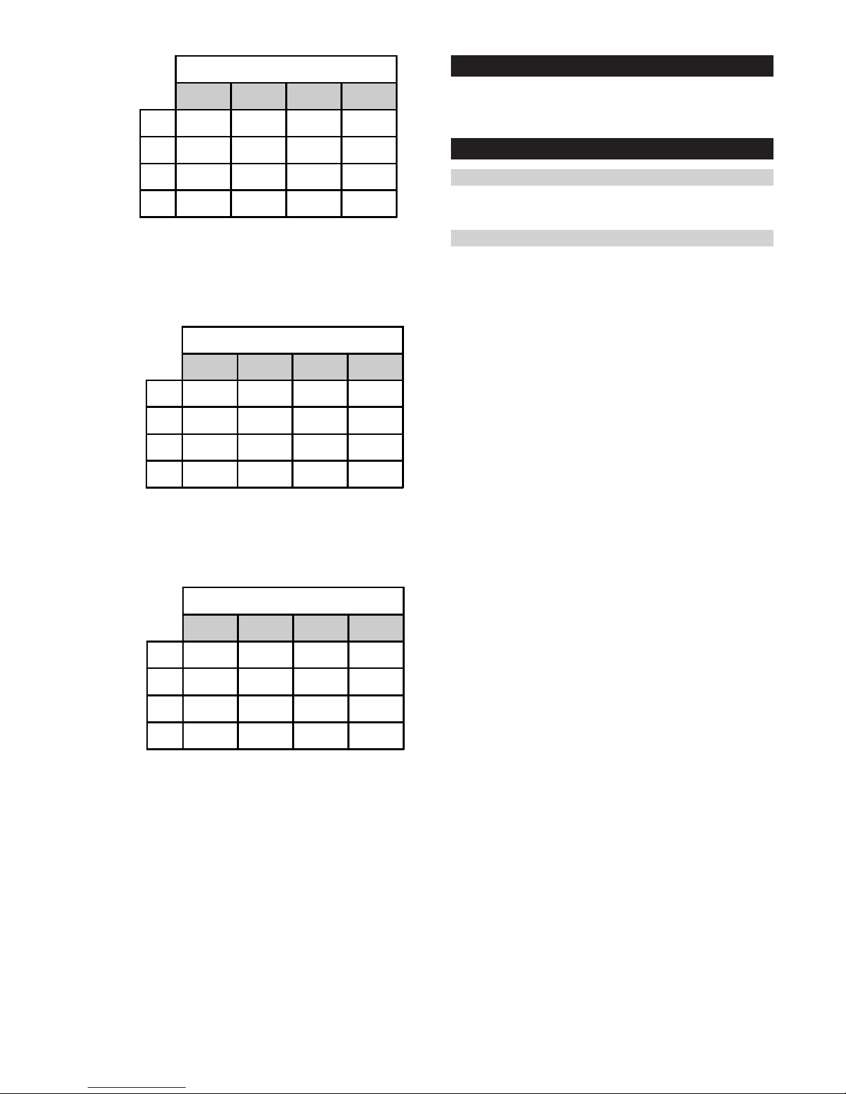
COLOR_TEMP=1
R_DRV B_DRV R_BKG B_BKG
26" TBD TBD TBD TBD
32" 262 240 504 504
40" 253 235 515 507
46" TBD TBD TBD TBD
22. Send ECS COLOR_SAVE command.
23. Set up COLOR_TEMP=2.
24. Write the correct values for R_DRV, B_DRV, R_BKG and B_BKG
from the table below.
COLOR_TEMP=2
R_DRV B_DRV R_BKG B_BKG
26"
TBD TBD TBD TBD
32"
262 218 507 509
40"
251 219 517 505
46"
TBD TBD TBD TBD
25. Send ECS COLOR_SAVE command.
26. Set up COLOR_TEMP=3.
27. Write the correct values for R_DRV, B_DRV, R_BKG and B_BKG
from the table below.
COLOR_TEMP=3
R_DRV B_DRV R_BKG B_BKG
26"
TBD TBD TBD TBD
32"
265 189 509 516
40"
260 198 511 500
46"
TBD TBD TBD TBD
28. Send ECS COLOR_SAVE command.
29. Switch the TV set OFF and then ON again to retain adjustment
values.
- 30 -
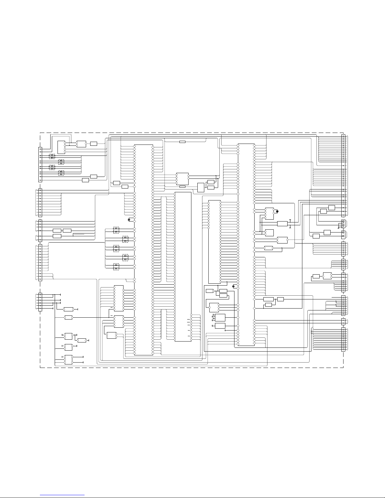
4-1. BLOCK DIAGRAMS (1)
IC5000
VIDEO PROCESSOR
RX0-
V6
W9
Y8
W6
Y9
W8
Y6
Y10
V8
Y5
V4
U4
W4
Y4
V9
M2
M1
N2
N1
P2
P1
L2
L1
U11
T11
W11
Y11
U12
V12
D19
C20
T10
Y20
C13
C11
B11
A11
A10
B10
C10
D10
D9
A8
B8
D6
A5
B5
A4
C5
A3
A2
A1
C8
D8
D7
C7
B7
C1
C2
C3
D3
K17
B2
B6
B9
B12
B1
A6
A9
A12
F1
F2
F4
G4
G3
G2
G1
H1
H2
H3
H4
Y7
Y-G1
D2-IN-L3/MODE
Y/CV
C
CN9000
1
HDMI
CONNECTOR
1
2
4
7
Q5001
BUFFER
TO G1/G2
BOARD
CN6200
3
2
17
16
IC5201
FET BUS SWITCH
MCLK0
CPU-CS
B1
PB-B1
PB-R1
Y-G2
PB-B2
PR-R2
Y-G3
PB-B3
PR-R3
FB1
FS1
FB2
FS2
CVBS1
C
TMDS-RX0-
HDMI-MCLK
PLUG-DET
V BLK
MD(0)
DSDA
DSCL
AUDIO CLK
SCK
WS
SDO
INTN
DPB VS
RESET TR
MD0
IC5500 DDR SRAM
158
64
63
PO1/DACKOX
49
CN1001
TO H3 BOARD
CN301
BE ( )
MAIN MICRO PROCESSOR
& VIDEO PROCESSOR
B13
A13
D12
A7
F3
W10
U8
V10
U10
TMDS-RX0+
TMDS-RX1-
TMDS-RX1+
TMDS-RX2-
TMDS-RX2+
TMDS-CLK-
TMDS-CLK+
DDC-SDA
DDC-SCL
HDMI-SCK
HDMI-WS
HDMI-SDO
INTN
MD(1)
MD(2)
MD(3)
MD(4)
MD(5)
MD(6)
MD(7)
MD(8)
MD(9)
MD(10)
MD(11)
MD(12)
MD(13)
MD(14)
MD(15)
MD(16)
MD(17)
MD(18)
MD(19)
MD(20)
MD(21)
MD(22)
MD(23)
MD(24)
MD(25)
MD(26)
MD(27)
MD(28)
MD(29)
MD(30)
MD(31)
62
61
60
59
58
57
47
48
46
45
43
44
42
41
70
71
69
72
68
67
66
65
56
55
54
53
51
52
50
49
141
9
11
8
10
37
40
38
39
25
24
23
22
21
20
19
18
17
16
15
14
12
13
6
5
7
MD(27)
MD(28)
MD(29)
MD(30)
MD(31)
MD(21)
MD(22)
MD(23)
MD(24)
MD(25)
MD(26)
MD(15)
MD(16)
MD(17)
MD(18)
MD(19)
MD(20)
MD(0)
MD(1)
MD(2)
MD(3)
MD(4)
MD(5)
MD(6)
MD(7)
MD(8)
MD(9)
MD(10)
MD(11)
MD(12)
MD(13)
MD(14)
RESET TR
INPUT V
DQS(3)
DQS(2)
DQS(1)
DQS(0)
DQS(3)
DQS(2)
DQS(1)
DQS(0)
DQM(3)
DQM(2)
DQM(1)
DQM(0)
DQM(3)
DQM(2)
DQM(1)
DQM(0)
MA(11) MA(11)
MA(10)
MA(9)
MA(8)
MA(7)
MA(6)
MA(5)
MA(4)
MA(3)
MA(2)
MA(1)
MA(0)
MA(4)
MA(3)
MA(2)
MA(1)
MA(0)
MA(8)
MA(7)
MA(6)
MA(5)
MA(10)
MA(9)
3
4
1
2
107
K3 DQ23
K2 DQ22
J2 DQ21
J3 DQ20
G2 DQ19
G3 DQ18
F2 DQ17
F3 DQ16
D2 DQ6
E2 DQ7
D3 DQ5
C2 DQ4
B6 DQ2
B5 DQ3
C6 DQ1
B7 DQ0
B9 DQ29
C9 DQ30
B10 DQ28
B8 DQ31
C13 DQ27
D12 DQ26
D13 DQ25
E13 DQ24
F12 DQ15
F13 DQ14
G12 DQ13
G13 DQ12
J13 DQ10
J12 DQ11
K12 DQ9
K13 DQ8
PB5/INT13/ICU1
H13 DQS1
B13 DQS3
B2 DQS0
H2 DQS2
B3 DQM0
B12 DQM3
H12 DQM1
H3 DQM2
M7 A11
L6 A10
M8 A9
N11 A8/AP
N10 A7
N9 A6
M9 A5
N8 A4
N7 A3
M6 A2
N6 A1
N5 A0 N13V REF
M12 CK
M11 CK
N2 CS
N12 CKE
L3 WE
M2 RAS
L2 CAS
M5 BA0
N4 BA0
BA0
E3
RX0+
RX1-
RX1+
RX2-
RX2+
RXC-
RXC+
PWR 5V
MD1
MD2
MD3
MD4
MD5
MD6
MD7
MD8
MD9
MD10
MD11
MD12
MD13
MD14
MD15
MD16
MD17
MD18
MD19
MD20
MD21
MD22
MD23
MD24
MD25
MD26
MD27
MD28
MD29
MD30
MD31
DRVS
DQS3
DQS2
DQS1
DQS0
DQM3
DQM2
DQM1
DQM0
MA11
MA10
MA9
MA8
MA7
MA6
MA5
MA4
MA3
MA2
MA1
MA0
PC-G
PC-B
PC-R
AIN-HS
AIN-VS
PC-G
PC-B
PC-R
PC-H
PC-V
E1
D1
J4
K2
K1
J2
J1
K4
K3
E20
BA0
BA1
CAS#
RAS#
WE#
CKE
CS#
MCLK0#
MV REF
F19
F18
F17
F20
G17
G18
G19
G20
H20
H19
H18
D20
E19
15
18
RD#
WR#
ALE
B2
B3
B4
4
19
A1
A2
A3
3
IC9711
INVERTER GATE
1A
12A6
1Y
ALE-PX
CS-PX
2
19
13
12
B5
11
14
B6
B7
B8
3
4
A1
A2
A3
17
16
15
18
6
5
7
8
9
IC5202
FET BUS SWITCH
B1
B2
B3
B4A4
A5
A6
A7
A8
OE
RD#
WR#
OE AD7
AD6
AD5
AD4
AD3
AD2
AD1
AD0
AD7
AD6
AD5
AD4
AD3
AD2
AD1
AD0
D2-IN-SW/FB
D1-IN-L3/MODE
D1-IN-SW/FB
D2-IN-CR
D2-IN-CB
D2-IN-Y
D1-IN-CR
D1-IN-CB
D1-IN-Y
D3-IN-CR
D3-IN-CB
D3-IN-Y
Q5000
BUFFER
W19
V18
W18
Y18
Y17
W17
V17
U17
Y15
DY0-AEP
DY1-AEP
DY2-AEP
DY3-AEP
DY4-AEP
DY5-AEP
DY6-AEP
DY7-AEP
DCLK-AEP
W1
Y1
B14
X5000
A14
2 3
41
L5000
INDUCTOR
B15
A15
2 3
41
L5001
INDUCTOR
B16
A16
2 3
41
L5002
INDUCTOR
B17
A17
2 3
41
L5003
INDUCTOR
B18
A18
2 3
41
L5004
INDUCTOR
RA-
RA+
RB-
RB+
RC-
RC+
RCLK-
RCLK+
RD-
RD+
Q9003
BUFFER
IC9001
EEPROM
7
6
WRT-PRT
2
7
IC9002
LEVEL SHIFTER
SCL A
6
3 5
WP
SCL
SDA
PLUG-DET
SDA A
SCL B
SDA B
DDC-SCL
DDC-SDA
CLK-
L9000 0uH
15
16
12
10
23
4
CLK+
1
23
4
1D1-6
4
23
4
D1+
1
23
4
L9002 0uH
L9001 0uH
L9003 0uH
D0+
D0-
D2D2+
7
9
3
1
DDC-CLK
DDC-DAT
18
Q9000
SWITCH
Q9001
SWITCH
19
DDC +5v
HPD
TDMS-CLKTDMS-CLK+
TDMS-RX0TDMS-RX0+
TDMS-RX1TDMS-RX1+
TDMS-RX2TDMS-RX2+
HDMI-RST
TDMS
CN4700
RESET DY0-AEP
DY1-AEP
DY2-AEP
DY3-AEP
DY4-AEP
DY5-AEP
DY6-AEP
DY7-AEP
DCLK-AEP
3
5
7
9
11
13
15
17
19
1 M-RST
AC DET
U2-TX
U-ACT
SPI-STATUS
U-CE
U-CLK
UD-OUT
U-DIN
DTT-RST
TO FEE BOARD
CN3400
30 RA-
RA+
RB-
RB+
RC-
RC+
RCLK-
RCLK+
RD-
RD+
28
26
24
22
20
18
16
14
12
6
4
1
DCC
DCC-LUT
DCC1/DCC2
CN5000
LCD PANEL
CN7009
2
1
4
BACKLIGHT
DIMMER
POWER 5
3 PANEL DET
Q7007
AMPLIFIER
Q7008
BUFFER
PANEL FAIL
Q1002
INVERTER
AC DET OFF
5
POWER ON6 POWER 1
S1 OFF
AC OFF DET AU
12
13
14 28
20
IC7000
5
1 2
5
1 2
IC7001
VOLTAGE REGULATOR
IC1010
9V REG
IC7002
VOLTAGE REGULATOR
PANEL 5V
FE5/6.2/10.5V
VD 1.8V
IC7004
SHUNT
IN OUT VDDMQ0
3.3V
A9VOUTVCC
17.5V
POWER 2
17.5V
POWER 2
17.5V
POWER 3
POWER 4
1 4
IC5203
EXC OR
POWER 2
VCC
CN1002
REG +18V
REG +18V
UNREG +33V
UNREG +10.5V
UNREG +10.5V
STBY 3.3V
8
10
REG +17.5V
DC DET
2
4
5
A OUT L
8
3
1
LRCLK
BCLK
DIN
IC9000
D/A CONVERTER
HDMI-MCLK
MCLK
A OUT R
HDMI-WS
HDMI-SCK
HDMI-SDO
HDMI
MUTING
Q9006,
Q9009,
Q9010,
D9014
HDMI-L
HDMI-R
R9070
HDMI-MUTE
INTN
Q9008
SWITCH
Q9007
SWITCH
DPA0
DPA1
DPA2
DPA3
DPA4
DPA5
DPA6
DPA7
DPA CLK
XTAL1
XTAL0
TA1M
TA1P
TB1M
TB1P
TC1M
TC1P
TCLK1M
TCLK1P
TD1M
TD1P
SDA
SCL
AD0
AD1
AD2
AD3
AD4
AD5
AD6
AD7
BA0
BA1
MCK0
CAS#
RAS#
WE#
CLKE
CSO#
MCK0#
MV REF
BA1
CAS#
RAS#
WE#
CKE
CS#
MCLK0
MCLK0#
MV REF
AD0
IC1002
FLASH MEMORY
30
32
34
36
39
41
43
45
11
28
AD1
AD2
AD3
AD4
AD5
AD6
AD7
WR#
RD#
DQ8
DQ2
DQ10
DQ11
DQ12
DQ13
DQ14
DQ15
WE#
CE#
48
1
2
3
4
5
6
7
8
9
16
17
18
29
31
33
35
38
40
42
44
25
24
23
22
21
20
19
26
12
A17
A5
A4
A13
A12
A11
A10
A9
A8
A19
A18
A17
A7
DQ0
DQ1
DQ2
DQ3
DQ4
DQ5
DQ6
DQ7
A0
A1
A2
A3
A4
A5
A6
CE#
RE
A17
IC1001
MAIN PROCESSOR
150
20
157
134
HDMI-RST
HDMI-HPG-DETI
WRT-PRT
DTT-RESET
128
11
15
16
10
9
8
7
6
5
4
55
56
51
50
49
48
47
46
45
59
58
57
44
169
170
171
172
173
174
175
176
37
38
39
40
41
42
43
18
68
A16
A15
A14
A13
A12
A11
A10
A9
A20
A19
A18
A8
D16
D17
D18
D19
D20
D21
D22
D23
A1
A2
A3
A4
A5
A6
A7
CS FLASH
RESET RESET
A17
A16
A15
A14
A13
A12
A11
A10
A9
A20
A19
A18
A8
D16
D17
D18
D19
D20
D21
D22
D23
A1
A2
A3
A4
A5
A6
A7
CS FLASH
V-BLK
RD#
WR#
AD7
AD6
AD5
AD4
AD3
AD2
AD1
AD0
66
64
X1001
6
IC1005
EEPROM
SDA
5
SCL
8
VCC
Q1007
BUFFER
IC1004
RESET
4
OUT
Q1004
BUFFER
7
115
114
24
EEPROM-WP
RESET
DC ALERT 1
CIRCUIT
Q7503, Q7504,
Q7505, Q7506
163
DC ALERT 1
D3.3V
VDDMQ0
VD1.8V
STBY 3.3V
DC ALERT 3
CIRCUIT
Q7500, Q7502
UNREG
10.5V
154
153
DC ALERT 3
DC ALERT 2
FE5/6.2/10.5V
30
19
21
25
165
ALE PX
CS-PX
DCC
DCC-LUT
DCC1/DCC2
D24
D25
D26
D27
D28
D29
D30
D31
WROX/DQMUU
RXD
PAO/INTO
A17/P51
A16/P50
A15
A14
A13
A12
A11
A10
A9
A20/P54
A19/P53
A18/P52
A8
D16/P20
D17/P21
D18/P22
D19/P23
D20/P24
D21/P25
D22/P26
D23/P27
A1
A2
A3
A4
A5
A6
A7
CSOX/P31
INTX
X1
X0
CS5X/P34
P40/BGR NTX
PE2/DEOP2X/TRG
149
112
81
32
111
83
138
139
140
123
62
113
26
61
101
155
DIMMER
BACKLIGHT
PANEL FAIL
POWER 1
POWER 5
S1 OFF
V-DET
HP-DET
SP MUTE
REC-MUTE
AUDIO RESET
LINE MUTE
AU-PROT
SP-SD MUTE
AU-OPT-OUT-MUTE
HP-MUTE
122
31
159
152
164
80
REC-R-LED
STBY-LED
ON-TIMER-LED
POWER RESERVE LED
AC MUTE LED
SENSOR DET
IC1009
REAL TIME CLOCK
XIN
3
XOUT
1
2
X1009
5
7
6
133
142
T-ALART
T-ALERM 2
IC1007
DIGITAL TEMP SENSOR
1
2
119
118
SDA
SCL
SDA
SCL
SDA
SCL
136
143
23
77
80
117
116
AV LINK OUT
AV LINK IN
AGC
AFT
TUNER SW
SDA-TUNER
SCL-TUNER
95
93
92
91
90
89
88
87
86
94
IBREAK
ICD3
ICD2
ICD0
IS2
IS1
ICLK
IS0
ICD1
TRSTX
71
Q1005
BUFFER AMP
FR/MD2
MH SYNC
Q1003
SWITCH
161
Q1006
BUFFER
MDO
76
130
108
109
110
82
151
99
100
KEY
POWER KEY
DC DET
B-INT
ECS-RXD
ECS-TXD
POWER 2
POWER 3
POWER 4
IC1003
COMPARATOR
5
1
+IN2
OUT 1
7
OUT 2
Q1001
SWITCHING
FET
SDA-B-5V
SCL-B-5V
Y1/G1D1-IN-Y
47
CB1/B1D1-IN-CB
45
CR1/R1D1-IN-CR
44
L3-1/MODE 1D1-IN-L3/MODE
43
NC/FB-1D1-IN-SW/FB
42
Y2/G2D2-IN-Y
40
CB2/B2D2-IN-CB
38
CR2/R2D2-IN-CR
37
L3-1/MODE 2D2-IN-L3/MODE
36
NC/FB-2D2-IN-SW/FB
34
Y3D3-IN-Y
32
CB3D3-IN-CB
30
CR3D3-IN-CR
28
SEL2-Y/CVY/CV
26
SEL2-CC
19
AC OFF DET
AU/TXR(AEP)
AC OFF DET AU
25
20
12
15
16
18
21
14
17
13
V-DETV-DET
REC-MUTE/TV-L(AEP)REC-MUTE
HP-DETHP-DET
SP-MUTESP-MUTE
RESET AUDIOAUDIO RESET
LINE MUTELINE MUTE
AU-PROTAU-PROT
SP-SD MUTESP-SD MUTE
AU-OPT-OUT-MUTEAU-OPT-OUT-MUTE
HP-MUTEHP-MUTE
3
1
11
9
23
22
HDMI-L
PC-IN-L
PC-IN-R
HDMI-R
24
SDA-B-5V
M-HSYNC
SCL-B-5V
7
5
35
DVI-L
DVI-R
NC/AV LINK/(AEP)
CN1008
RLLR
AUDIO IN
Q9004
BUFFER
AMP
Q9004
BUFFER
AMP
TO AE BOARD
CN9501
J9000
3
REC-RESERVEREC-R-LED
4
5
6
7
8
10
STBY-LED
ON-TIMER
PWR/RESERVE
AC MUTE
BL-IN
STBY-LED
ON-TIMER-LED
POWER RESERVE LED
AC-MUTE-LED
SENSOR-DET
SIRCS
CN1700
6
8
10
4
TO TUE BOARD
CN3903
AGC
AFT
TUNER-SW
SDA-TUNER
SCL-TUNER
CN6000
IC6000
EEPROM
8
5
PC-SDA
PC-SCL
6
SDA
SCL
VCC
PS6000
0.4A
2
12
15
9
2
3
6
13
14
PC-G
PC-B
PC-R
PC-H
PC-V
CN1004
EXTERNAL
CONNECTION
13
6
3
16
2
17
15
4
9
10
3
2
2
3
4
5
6
7
8
9
10
11
12
14
CN1007
CN1003
DTT-LOG
MDO
RXD
RXD
TXD
TXD
ECS-RXD
ECS-TXD
B-INT
RESET
TRI-SDA
TRI-SCL
KEY 1
POWER INT
EXTERNAL
CONNECTION
TO H1 BOARD
CN101
NO
CONNECTION
TRSTX
XRSTIN
INITX
IBREAK
ICD3
ICD2
ICD1
ICD0
IS2
IS1
IS0
ICLK
IC1008
LOGIC IC(SIRCS)
2Y
611
SIRCS
129
CH-IRQ
4Y
156
SIRCS
PC-IN-R
PC-IN-L L
R
EXTERNAL
CONNECTION
J6000
Q6000
BUFFER
AMP
Q6001
BUFFER
AMP
PLUG DET
R9048
PLUG DET HDMI-MPG-DET1
SD VIDEO
G1/G2 BOARD
CN6203
G1/G2 BOARD
CN6202
V OUT
ON/OFF
ON/OFF
V OUT
TRI-SDA
TRI-SCL
 Loading...