


KDL-19BX200
- 1 -
SERVICE MANUAL
AZ1-BK(5-3)
CHASSIS
MODEL DEST
RM-ED037
KDL-19BX200 AEP / UK / RUSS KDL-22BX200 AEP / UK / RUSS
MODEL DEST

- 2 -
TABLE OF CONTENTS
Section Title Page Section Title Page
1. GENERAL
Caution ................................................................ 3
Specifications ...................................................... 4
Connectors .......................................................... 6
2. DISASSEMBLY
2-1. Stand Assy Removal ............................................. 7
2-2. Rear Cover Removal ............................................. 7
2-3. Side Jack Bracket Removal ................................... 7
2-4. Loudspeaker Removal ........................................... 7
2-5. Switch Unit Board Removal ................................. 8
2-6. Power Unit Board Removal ................................... 8
2-7. Main Board Removal ............................................ 8
3. SERVICE MENUS
3-1. How to enter the Service Mode .......................... 9
3-2. Service Menu Structure ...................................... 9
3-2-1. Option 0 Menu .............................................. 9
3-2-2. Option 1 Menu .............................................. 9
3-2-3. Option 2 Menu ............................................. 10
3-2-4. Sound Options Menu ................................... 10
3-2-5. IF Settings Menu
.......................................... 10
3-2-6.
Adjustment Menu ......................................... 10
3-2-7. P
anel Adjustments Menu ............................. 10
3-2-8. Software Version Menu
................................ 10
4. DIA
GRAMS
4-1. Block Diagram ................................................... 11
4-2. Circuit Board Location ....................................... 12
5. EXPLODED VIEWS
5-1. Chassis ................................................................ 13
5-2. Bezel Assy & Stand Assy .................................... 15
5-3. Rear Cover Assy & Power Supply Cords ............ 16
6. PARTS LIST
............................................................... . 17
SAFETY-RELATED COMPONENT WARNING !!
COMPONENTS IDENTIFIED BY SHADING AND MARKED ON
THE EXPLODED VIEWS AND IN THE PARTS LIST ARE CRITICAL
FOR SAFE OPERATION. REPLACE THESE COMPONENTS WITH
SONY PARTS WHOSE PART NUMBERS APPEAR AS SHOWN IN
THIS MANUAL OR IN SUPPLEMENTS PUBLISHED BY SONY.
WARNING !!
AN ISOLATION TRANSFORMER SHOULD BE USED DURING ANY
SERVICE WORK TO AVOID POSSIBLE SHOCK HAZARD DUE TO
LIVE CHASSIS, THE CHASSIS OF THIS RECEIVER IS DIRECTLY
CONNECTED TO THE POWER LINE.
- 3 -
SECTION 1 GENERAL
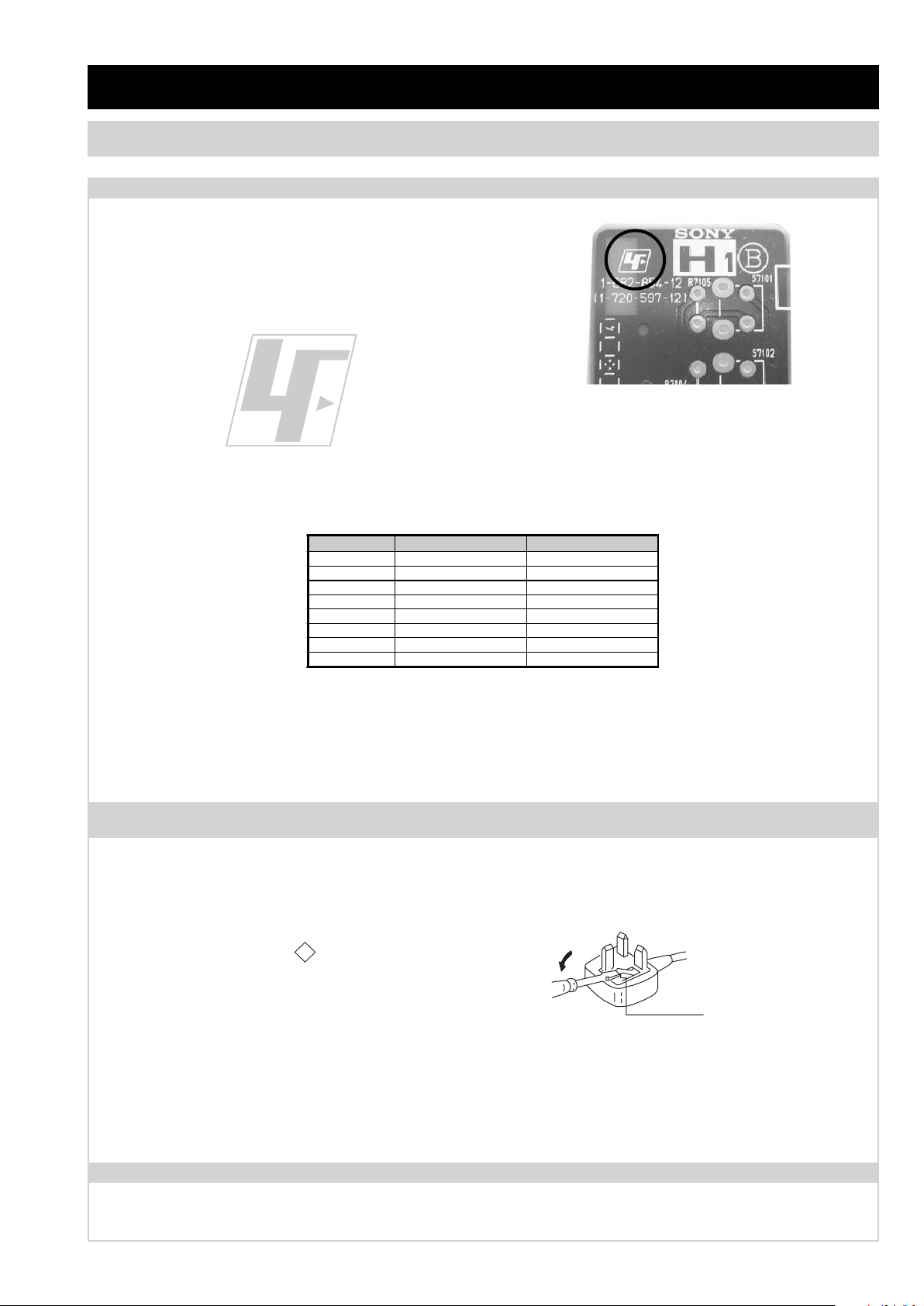
The circuit boards used in these models have been processed using
Lead Free Solder. The boards are identified by the LF logo located
close to the board designation e.g. H1 etc [ see example ]. The
servicing of these boards requires special precautions to be taken as
outlined below.
Lead Free Soldered Boards
example
Lead Free Solder material must be used to comply with environmental requirements of new solder joints. Lead Free Solder is available
under the following part numbers :
Due to the higher melting point of Lead Free Solder the soldering iron tip temperature needs to be set to 370 degrees centigrade. This
requires soldering equipment capable of accurate temperature control coupled with a good heat recovery characteristics.
For more information on the use of Lead Free Solder, please refer to http://www.sony-training.com
Partnumber Diameter Remarks
7-640-005-19 0.3mm 0.25Kg
7-640-005-20 0.4mm 0.50Kg
7-640-005-21 0.5mm 0.50Kg
7-640-005-22 0.6mm 0.25Kg
7-640-005-23 0.8mm 1.00Kg
7-640-005-24 1.0mm 1.00Kg
7-640-005-25 1.2mm 1.00Kg
7-640-005-26 1.6mm 1.00Kg
CAUTION
SECTION 1 GENERAL
How to replace the fuse.
Open the fuse compartment with
a screwdriver blade and replace
the fuse.
FUSE
WARNING (UK Models only)
The flexible mains lead is supplied connected to a B.S. 1363 fused
plug having a fuse of the correct rating for the set. Should the fuse
need to be replaced, use a fuse of the same rating approved by ASTA
to BS 1362, ie one that carries the
ASA
T
mark.
mark.
IF THE PLUG SUPPLIED WITH THIS APPLIANCE IS NOT SUITABLE
FOR THE OUTLET SOCKETS IN YOUR HOME, IT SHOULD BE CUT
OFF AND AN APPROPRIATE PLUG FITTED. THE PLUG SEVERED
FROM THE MAINS LEAD MUST BE DESTROYED AS A PLUG WITH
BARED WIRES IS DANGEROUS IF ENGAGED IN A LIVE SOCKET.
When an alternative type of plug is used, it should be fitted with the
correct rating fuse, otherwise the circuit should be protected by the
same rating fuse at the distribution board.
UK PLUG WARNING
LCD PANEL CAUTION
Whilst working on this product, it is not recommended to lay the TV set face down when powered up, as this can result in panel problems.
If it is necessary to power up the TV set when face down, the time should be minimised as much as possible.
- 4 -
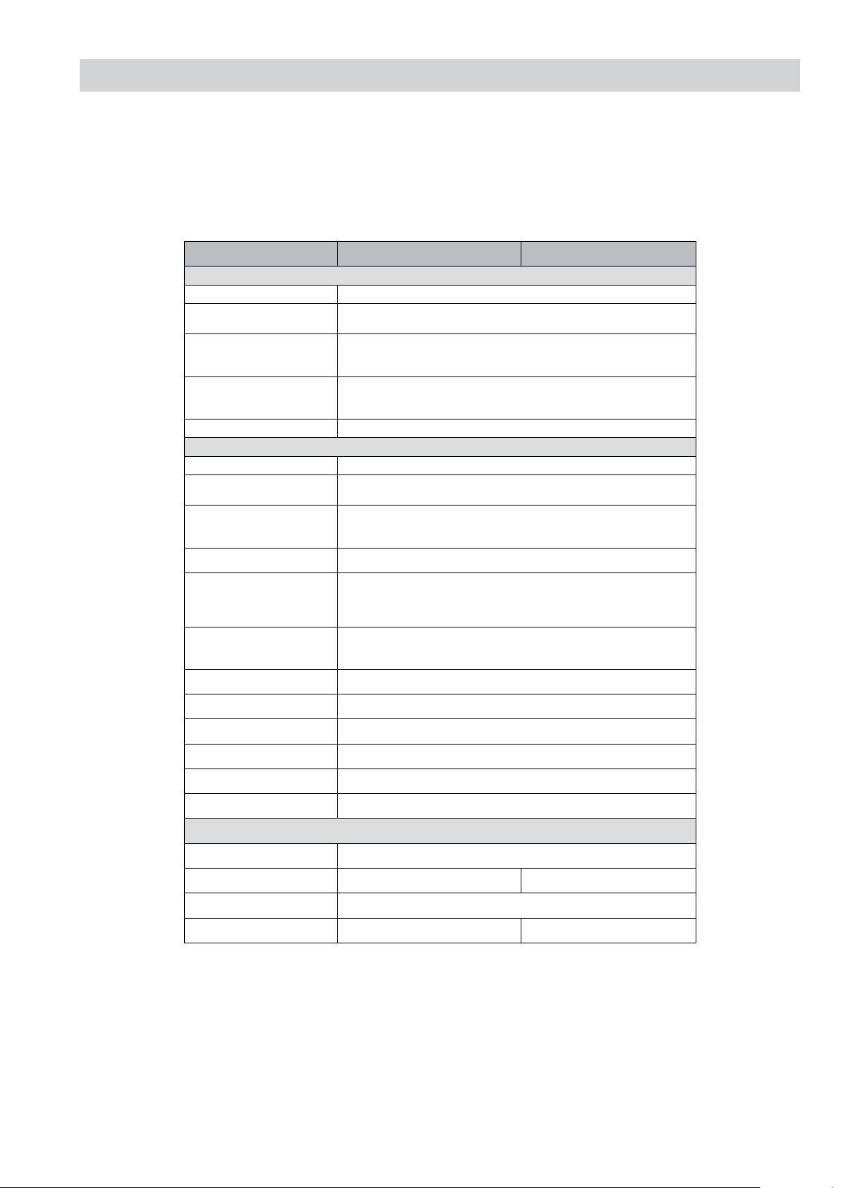
SPECIFICATIONS
Specifications
Model name
KDL-19BX200 KDL-22BX200
System
Panel System LCD (Liquid Crystal Display) Panel
TV System Analogue: Depending on your country/region selection: B/G, D/K, I, L
Digital: DVB-T
Colour/Video System Analogue: PAL, PAL60 (only video input), SECAM, NTSC3.58, NTSC4.43 (only
video input)
Digital: MPEG-2 MP@ML/HL, H.264/MPEG-4 AVC MP/HP@L4
Channel Coverage Analogue: VHF:E2-12 / UHF: E21-E69 / CATV:S1-S20 / HYPER: S21-S41 /
D/K: R1-R12, R21-R69 / L: F2-F10,B-Q, F21-F69 / I: UHF B21-B69
Digital: VHF / UHF
Sound Output 3 + 3 W
Input/Output jacks
Aerial / Cable 75 ohm external terminal for VHF / UHF
i / I / J AV1
21-pin scart connector including audio / video input, S-Video input, RGB input and TV
audio/video output.
I / Y Pb Pr IN
Supported formats: 1080p, 1080i, 720p, 576p, 576i, 480p, 480i
Y: 1 Vp-p, 75 ohm, 0.3V negative sync. / Pb/Cb: 0.7 Vp-p, 75 ohm /
Pr/Cr: 0.7 Vp-p, 75 ohm
o Y Pb Pr IN
Audio input (mini jack)
HDMI IN Supported formats: 1080/24p 1080p, 1080i, 720p, 576p, 576i, 480p, 480i
Audio: Two channel linear PCM: 32, 44.1 and 48 kHz, 16, 20 and 24 bit,
Dolby Digital 32, 44,1 and 48 kHz, Max bit rate 640 kHz
PC input (see page 5)
I PC
PC input (D-sub 15-pin) (see page 5)
G: 0.7 Vp-p, 75 ohm, non Sync on Green/B: 0.7 Vp-p, 75 ohm /
R: 0.7 Vp-p, 75 ohm
o PC
Audio input (mini jack)
M AV2
Video input (phono jack)
o AV2
Audio input (phono jacks)
i
Headphones jack input
H
USB input
G
CAM (Conditional Access Module) input
Power and others
Power Requirements 220-240V AC, 50 Hz
Screen Size (measured diagonally) 19 inches / Approx. 47 cm 22 inches / Approx. 55 cm
Display Resolution 1,366 dots (horizontal) x 768 lines (vertical)
Power Consumption 27.0 W 43.0 W
- 5 -
Standby Power Consumption 0.76 W
Average annual energy
Consumption
*1
39 kWh 63 kWh
Dimensions
(W x H x D)
(Approx)
(with stand) 457.3 x 334.5 x 152.6 mm 524.5 x 375.2 x 152.6 mm
(without stand) 457.3 x 310.8 x 62.8 mm 524.5 x 352.3 x 66.7 mm
Mass
(Approx.)
(with stand) 4.0 Kg 4.5 Kg
(without stand) 3.7 Kg 4.3 Kg
Design and specifications are subject to change without notice.
*1 4 hours a day and 365 days a year.
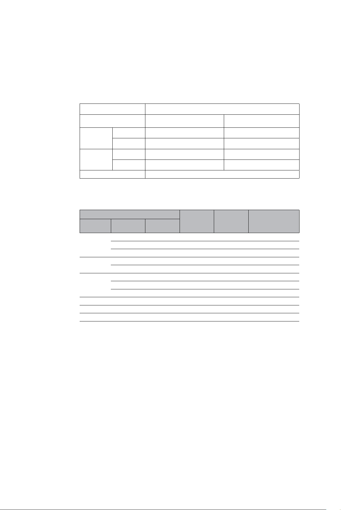
PC Input Signal Reference Chart for PC and HDMI IN
Resolution Horizontal
frequency
(kHz)
Vertical
frequency (Hz)
Standard
Signals Horizontal
Pixel
Vertical
(Line)
VGA 640 480 31.5 60 VESA
640 480 37.5 75 VESA
720 400 31.5 70 VESA
SVGA 800 600 37.9 60 VESA
800 600 46.9 75 VESA
XGA 1024 768 48.4 60 VESA
1024 768 56.5 70 VESA
1024 768 60.0 75 VESA
WXGA 1280 768 47.8 60 VESA
1280 768 47.4 60 VESA
1360 768 47.7 60 VESA
?
• For the best picture quality, it is recommended to use the signals in the above chart with a 60 Hz vertical
frequency (boldfaced).
- 6 -
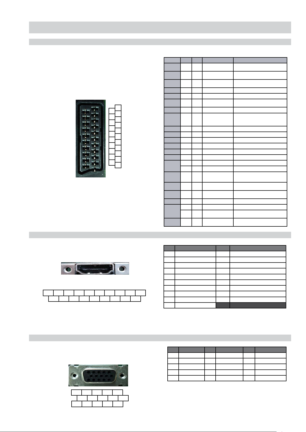
CONNECTORS
21 Pin Connector (SCART)
HDMI Connector
15 Pin D Sub Connector (PC)
Pin No AV-1 AV-2 Signal Signal Level
1 • • Audio Output B
(Right)
Standard Level: 0.5V rms
Impedance: less than 1KΩ*
2 • • Audio Input B
(Right)
Standard Level: 0.5V rms
Impedance: more than 10KΩ*
3 • • Audio Output A
(Left)
Standard Level: 0.5V rms
Impedance: less than 1KΩ*
4 • • Ground (Audio)
5 • • Ground (Blue)
6 • • Audio Input A (Left) Standard Level: 0.5V rms
Impedance: more than 10KΩ*
7 • • Blue Input 0.7V +/- 3dB, 75Ω, positive
8 • • Function Select
(AV control)
High State (9.5~12V): AV mode
Low State (0~2V): TV mode
Impedance: more than 10KΩ*
Capacitance: less than 2nF
9 • • Ground (Green)
10 - • AV Link
11 • • Green Input 0.7V +/- 3dB, 75Ω, positive
12 - • Open
13 • • Ground (Red)
14 • • Ground (Blanking)
15
• • Red Input 0.7V +/- 3dB, 75Ω, positive
• • S signal Chroma Input 0.3V +/-3dB, 75Ω, positive
16 • • Blanking Input
(Y Signal)
High State (1~3V)
Low State (0~0.4V)
Impedance: 75Ω
17 • • Ground
(Video Output)
18 • • Ground
(Video Input)
19 • • Video Output 1V +/-3dB, positive sync 0.3V (-3+10dB)
20
• • Video Input 1V +/-3dB, positive sync 0.3V (-3+10dB)
• • Video Input Y
(S Signal)
1V +/-3dB, positive sync 0.3V (-3+10dB)
21
• • Common Ground
(Shield)
1
3
5
7
9
11
13
15
17
19
21
2
4
6
8
10
12
14
16
18
20
19 17 15 13 11 9 7 5 3 1
18 16 14 12 10 8 6 4 2
5 4 3 2 1
10 9 8 7 6
15 14 13 12 11
Pin No Signal Assignment Pin No Signal Assignment Pin No Signal Assignment
1 Red Output 6 Red Return 11 Monitor IDO in display
2 Green Output 7 Green Return (Ground) 12 DCC Serial Data
3 Blue Output 8 Blue Return (Ground) 13 Horizontal Sync
4 Unused 9 +5V DC 14 Vertical Sync
5 Ground 10 Sync Return (Ground) 15 DCC Serial Clock
Pin No Signal Assignment Pin No Signal Assignment
1 TMDS Data2+ 11 TDMS Clock Shield
2 TMDS Data2 Shield 12 TMDS Clock-
3 TMDS Data2- 13 CEC
4 TMDS Data1+ 14 Reserved (N.C. on device)
5 TMDS Data1 Shield 15 SCL
6 TMDS Data1- 16 SDA
7 TMDS Data0+ 17 DDC/CEC Ground
8 TMDS Data0 Shield 18 +5V power
9 TMDS Data0- 19 Hot Plug Detect
10 TMDS Clock+
 Loading...