


 Loading...
HISTORY INFORMATION FOR THE FOLLOWING MANUAL:
SERVICE MANUAL (COMMON)
GN2TR CHASSIS
Segment: QEL
Version |
Date |
Subject |
1 |
06/2016 |
1st Issue. |
2 |
08/2016 |
Add Appendix 1 : Reset vs. Factory Reset ( pg 168 ) |
LCD TV
9-888-701-02
For SM - Unique , please refer :
9-888-701-Px ( Asia)
9-888-701-Ax ( America)
9-888-701-Ex ( Europe )
9-888-701-C1 ( China )
9-888-701-Jx ( Japan )

SERVICE MANUAL (COMMON)
GN2TR CHASSIS
Segment: QEL
LCD TV

MODEL LIST
THIS SERVICE MANUAL CONTAINS COMMON INFORMATION FOR BELOW REGIONS AND MODELS:
REGION |
|
|
|
|
ASIA |
AMERICA |
EUROPE |
CHINA |
JAPAN |
MODEL
KD-49X7*D KD-55X7*D
KD-49XD7* KD-55XD7*
KJ-49X7*D XBR-55X7*D
XBR-49X7*D

TABLE OF CONTENTS
Section Title |
Page |
1. SAFETY NOTES |
|
Warnings and Caution………………………………………………………. |
5 |
Caution Handling of LCD Panel ......…………….................................... |
5 |
Caution About the Lithium Battery……………......................................... |
6 |
Safety Check Out ........................……………......................................... |
6 |
Leakage Test .......................................................................................... |
6 |
How to Find a Good Earth Ground………………………………………… |
6 |
Lead Free Information….…………………………………………………… |
7 |
Handling the Flexible Flat Cable (FFC)……………………………………. |
7 |
Assemble and Dissemble Tuner Module …………………………..……. |
9 |
2. SELF DIAGNOSTIC FUNCTION |
|
Self Diagnosic ……………...................................................................... |
10 |
3. TROUBLE SHOOTING |
|
Troubleshooting Items …………………………………………………….. |
14 |
No Power…….……………………………………………………………….. |
15 |
LED Blinking............................................................................................. |
40 |
No Sound.............................………………………………………….......... |
76 |
No Picture................................................................................................. |
94 |
Side Buttons Malfunction ……………………………………………………. |
138 |
Network Malfunction …………………………………………………………… |
144 |
Section Title |
Page |
4. SERVICE ADJUSTMENTS |
|
How to Enter Service Mode............................................................. |
153 |
Software Version ……………....................……….……………………… |
154 |
Serial Number Edit ………………..………………………………..…….. |
155 |
Model Number Setting ………….…..……………………………………... |
157 |
WB Adjustment ………………………………….………………………….. |
158 |
WB/Mura/CUC data transfer ……........................................................ |
159 |
HDD Performance Check....................................................................... |
160 |
HDD Re-Register ………………………………………………………….. |
161 |
Summary of Service Control ……………………………………………… |
162 |
How to Enter Self Diagnosis Display …………………………………….. |
163 |
5. DIAGRAMS |
|
Circuit Board Location ......................................................................... |
164 |
Block Diagram...................................................................................... |
165 |
Connector Diagram ………………………………………...................... |
166 |
Please refer Service Manual – Unique for below information : -Safety Warnings
-Wire Dressing -Circuit Board Location
-Disassembly and Exploded View.
Note: Pictures provided in this Service Manual might have slight difference from the actual sets.
4

SECTION 1
SAFETY NOTES
1-1. Warnings and Caution
1)These servicing instructions are for use by qualified service personnel only.
2)To reduce the risk of electric shock, do not perform any servicing other than that contained in the operating instructions unless you are qualified to do so.
3)An isolation transformer should be used during any service to avoid Possible shock hazard, because of live chassis. The chassis of this receiver is directly connected to the ac power line.
4)Be sure to follow these guidelines to protect your property and
avoid causing serious injury :
•Carry the TV with an adequate number of people; larger size TVs require two or more people.
•Correct hand placement while carrying the TV is very important for safety and to avoid damages.
5) Components identified by shading and ! mark on the exploded views, and in the parts list are critical for safe operation. Replace these components with Sony parts whose part numbers appear as shown in this manual or in supplements published by Sony. Circuit adjustments that are critical for safe operation are identified in this manual. Follow these procedures whenever critical components are replaced or improper operation is suspected.
1-2. Caution Handling of LCD Panel
When repairing the LCD Panel, make sure you are grounded with a wrist band. When repairing the LCD Panel on the wall, the panel must be secured using the 4 mounting holes on the rear cover.
1)Do not press the panel or frame edge to avoid the risk of electric shock.
2)Do not scratch or press on the panel with any sharp objects.
3)Do not leave the module in high temperature or in areas of high humidity for an extended period of time.
4)Do not expose the LCD panel to direct sunlight.
5)Avoid contact with water. It may cause short circuit within the module.
6)Disconnect the AC power when replacing the backlight (CCFL) or
inverter circuit. (High voltage occurs at the inverter circuit at 650Vrms)
7)Always clean the LCD panel with a soft cloth material.
8)Use care when handling the wires or connectors of the inverter circuit. Damaging the wires may cause a short circuit.
9)Protect the panel from ESD to avoid damaging the electronic circuit (C-MOS).
10)During the repair, DO NOT leave the Power On or Burn-in period for more than 1 hour while the TV is face down on a cloth.
Figure 1. TV is faced down on a cloth during repair.
5

1-3. Caution About the Lithium Battery
1) Danger of explosion if battery is incorrectly replaced. Replace only with the same or equivalent type.
2) Outer case broken battery should not contact to water.
1-4. Safety Check-Out
After correcting the original service problem, perform the following safety checks before releasing the set to the customer:-
1)Check the area of your repair for unsoldered or poorly soldered connections. Check the entire board surface for solder splashes and bridges.
2)Check the inter board wiring to ensure that no wires are pinched or
contact high-wattage resistors.
3)Check all control knobs, shields, covers, ground straps and mounting hardware have been replaced. Be absolutely certain you have replaced all the insulators.
4) Look for unauthorized replacement parts, particularly transistors that
were installed during a previous repair. Point them out to the customer and recommend their replacement.
5)Look for parts which, though functioning show obvious signs of deterioration. Point them out to the customer and recommend their replacement.
6)Check the line cords for cracks and abrasion. Recommend the
replacement of any such line cord to the customer.
7) Check the antenna terminals, metal trim, metalized knobs, screws and all other exposed metal parts for AC leakage. Check leakage test as described next.
8. For safety reasons, repairing the Power board and/or Inverter board is prohibited.
1-5.Leakage Test
(To protect electric shock when customer touch the terminal.)
Leakage current can be measured by V: Voltmeter or oscilloscope (r.m.s. or peak reading)
Stabilized power supply instrument and isolated voltage transformer: Use too much current capacity and isolated voltage transformer does not need to use stabilized power supply equipment.
Specification of RMS volt meter: Input resistance > 1 Mohm, Input capacitance < 200 pF, Frequency range: 15 Hz – 1MHz . Refer Figure 1. Isolated type volt -meter (FLUKE 8921A etc *1)
*1 Not use FLUKE 8920A that connected to protective earth by diode
#Leakage currentof measurementinstrumentis less than 10μArms when under test equipment AC plug is opened
#Set up the following condition and turn on the set. Applied voltage: Nominal input voltage (Description on Nameplate)
#Measure the leakage current between one phase conductor and neutral for terminal 1 and terminal
2. Read rms value, and then calculate to peak value PEAK VALUE =√2
RMS VALUE
Comply with the following requirement
Class II equipment (2-pin plug): for each terminal, the worst value of measurement must not exceed AC 283uA peak).
Note: including AC adaptor, AC adaptor/DC operated unit combination Note: Products which are always used in touch with human body: 141uA (peak)
Note: As for products destined for Southeast Asia (Rod Antenna is accessory. Or it is packed with a product.), the worst value must not exceed AC 141uA (peak).
Figure 1 – Measuring network for Leakage Current
6
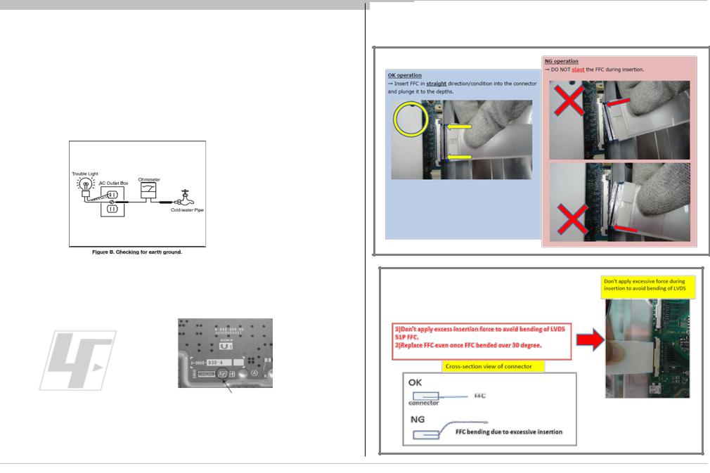
1-6. How to Find a Good Earth Ground
1)A cold-water pipe is a guaranteed earth ground; the cover-plate retaining screw on most AC outlet boxes is also at earth ground.
2)If the retaining screw is to be used as your earth ground, verify that it is at ground by measuring the resistance between it and a cold-water pipe with an ohmmeter. The reading should be zero ohms.
3)If a cold-water pipe is not accessible, connect a 60to 100-watt troublelight (not a neon lamp) between the hot side of the receptacle and the retaining screw. Try both slots, if necessary, to locate the hot side on the line; the lamp should light at normal brilliance if the screw is at ground potential (see Figure 3).
Figure 3. Checking for earth ground.
1-7. Lead Free Information
The circuit boards used in these models have been processed using Lead Free Solder. The boards are identified by the LF logo located close to the board designation.
Figure 4: LF Logo |
Figure 5: LF logo on circuit board |
The servicing of these boards requires special precautions. It is strongly recommended to use Lead Free Solder material in order to guarantee optimal quality of new solder joints.
1-8. Handling the FLEXIBLE FLAT CABLE (FFC)
When you insert / pull out FFC, please grasp a reinforcement board and main body of FFC.
7

<INSERTION>
Insert properly without slanting
<PULL OUT>
Press release button at the same time pull out FFC cable
8
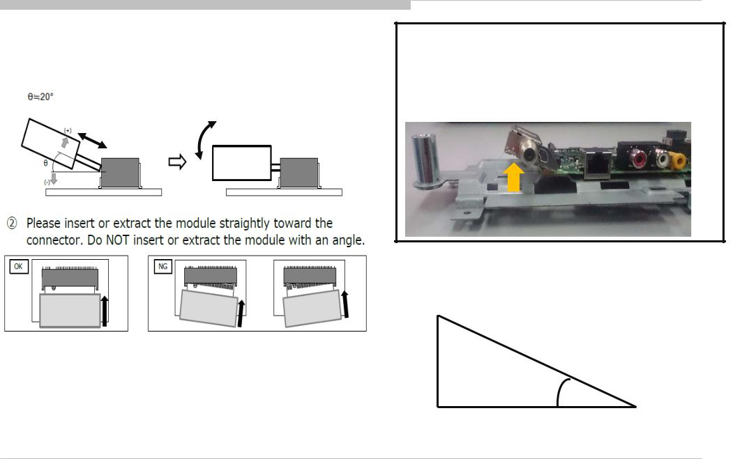
1-9. Assemble and Dissemble Tuner Module
Tuner Module treatment way
1.The insertion & extraction angle of the module is permitted to specified degree for connector
Push down to screw.
For removing Tuner Module,
After un screwed, Automatically the Module will float to correct degree.
So please extract it with keeping this degree.
20°
Reference paper for 20 degree
(If need please use for fit by cutting this paper)
20°
9

SECTION 2
SELF DIAGNOSTIC FUNCTION
The units in this manual contain a self-diagnostic function. If an error occurs, the Smart Core Red LED will automatically begin to flash. The number of times the LED flashes translates to a probable source of the problem.
A definition of the Smart Core Red LED flash indicators is listed in the instruction manual for the user’s knowledge and reference.
If an error symptom cannot be reproduced, the remote commander can be used to review the failure occurrence data stored in memory to reveal past problems and how often these problems occur.
DIAGNOSTIC TEST INDICATORS
When an error occurs, the Smart Core Red LED will flash a set number of times to indicate the possible cause of the problem.
If there is more than one error, the LED will identify the first of the problem areas.
Result for all of the following diagnostic items are displayed on screen.
If the screen displays a “0”, no error has occurred .
|
Smart Core RED |
QM-L/QH-L/QH2/QE-L/QE |
|
|
|
|
LED blinking count |
|
|
|
|
|
|
|
|
|
|
|
2x |
<B/G/A> Main 12V over voltage [MAIN_POWER] |
|
|
|
|
|
|
|
|
|
|
3x |
<B> Main 5.0V failure [DC_ALERT] |
|
|
|
|
|
|
|
|
|
|
<B/S> Audio amp. protection [AUD_ERR] |
|
|
|
|
|
|
|
|
|
|
|
|
|
|
|
|
|
4x |
None |
|
|
|
|
|
|
|
blue italic: detect at startup sequence only. |
|
|
|
<P/T/G/B> Panel ID EEPROM I2C No ACK (Also panel power |
|
||
|
5x |
|
<G>: Power supply board, |
||
|
failure is a suspect) [P_ID_ERR] |
|
<B>: Main board, |
||
|
|
|
|||
|
|
|
|
<T>: T-con board |
|
|
6x |
<G/P/B/LD> Backlight failure [BACKLIGHT] |
|
<LD> LD board (if AC adapter model, it would |
|
|
|
|
|
power supply for Set) |
|
|
|
|
|
||
|
7x |
Over temperature protection [TEMP_ERR] |
|
<P>: Panel module |
|
|
<B> Temp. sensor I2C No ACK [TEMP_ERR] |
|
<S>: Speaker |
||
|
|
|
<A>: Power Adapter, |
||
|
8x |
None |
|
<D>: 4KBE + audio board (w/ 4KBE only), |
|
|
|
<Tu>: Tuner board (w/o 4KBE only) |
|||
|
|
|
|
|
|
|
|
|
|
|
|
10
|
|
|
|
|
|
|
|
|
|
|
|
|
|
|
Record Only |
QM-L/QH-L/QH2/QE-L/QE |
|
|
|
|
|
Item |
|
|
|
|
|
|
|
|
|
|
|
|
|
|
<B/Tu> Tuner & Demodulator I2C |
|
|
|
|
|
TU_DEMOD |
communication failure |
|
|
|
|
|
|
Tuner board set detect |
|
|
Blue italic: detect at startup sequence only. |
|
|
|
|
|
|
<G>: Power supply board, |
|
|
|
|
|
|||
|
TCON_ERR |
None |
|
|
<B>: Main board, |
|
|
|
|
<T>: T-con board, |
|
||
|
|
|
|
|
<TE>: Temp Censor board, |
|
|
|
|
|
|
<LD> LD board (if AC adapter model, it would power |
|
|
|
<T> FRC device is not finished Initial sequence |
|
|||
|
FRCTC_I2C |
|
|
supply for Set) |
|
|
|
FRC device I2C communication failure |
|
|
<P>: Panel module |
|
|
|
|
|
|
|
||
|
|
|
|
|
<S>: Speaker |
|
|
|
|
|
|
<A>: Power Adapter, |
|
|
AUD_ERR_I2C |
None |
|
|
<D>: 4KBE + audio board (w/ 4KBE only), |
|
|
|
|
|
|
<Tu>: Tuner board (w/o 4KBE only) |
|
|
|
|
|
|
|
|
11

|
|
|
|
|
|
|
|
|
|
|
|
|
|
|
|
|
|
|
|
|
|
|
|
|
|
|
|
|
|
|
|
|
|
|
|
Entry (Self Diagnosis Display) |
|
|
|
|
|
|
|
|
|
|
|
|
|
|
|
|
|
|
|
|
|
|
|
|
|
|
|
|
|
|
|
|
|
|
- Go to the standby by a remote. |
|
|
|
|
|
|
|
|
|
|
|
|
|
|
|
|
|
|
|
|
|
|
|
|
|
|
|
|
|
|
|
|
|
|
- Push the buttons sequentially: |
|
|
|
|
|
|
|
|
|
|
|
|
|
|
|
|
|
|
|
|
|
|
|
|
|
|
|
|
|
|
|||
|
|
|
|
|
|
|
|
|
|
|
|
|
|
|
|
|
|
|
|
|
|
|
|
|
|
Error count |
|
|
|
|||||
|
<Display><5><Vol-><Power> |
|
|
|
|
|
|
|
Error Item |
SELF CHECK |
|
|
|
|
|
|
|
|
|
|
|
|||||||||||||
|
|
|
|
|
|
|
|
|
|
|
|
|
|
|
|
|
|
|
||||||||||||||||
|
Exit |
|
|
|
|
|
|
|
|
|
|
|
|
|
|
|
|
|
|
|
|
|
|
|
|
|||||||||
|
|
|
|
|
|
|
|
|
|
|
|
|
|
|
|
|
|
|
|
|
|
|
|
|
||||||||||
|
|
|
|
|
|
|
|
|
|
|
|
|
|
|
|
|
|
|
|
|
|
|
|
|
|
|
|
|
|
|
|
|
||
|
-If you want to finish service mode app, do AC OFF/ON |
|
|
|
|
|
|
|
|
|
|
|
|
|
|
|
|
|
|
|
|
|
|
|
|
|
|
|
||||||
|
|
|
|
|
|
|
|
|
|
|
|
|
|
|
|
|
|
|
|
|
|
|
|
<< |
|
|
|
|||||||
|
→*Service mode app is disable perfectly |
|
|
|
|
|
|
002 |
|
MAIN POWER |
|
|
|
000000000000 |
|
|
000000000000 |
|
|
000000000000 |
000 |
|||||||||||||
|
-if you want to move home menu, push <HOME>button |
|
003 |
|
DC ALERT |
|
|
|
000000000000 |
|
|
000000000000 |
|
|
000000000000 |
|||||||||||||||||||
|
|
003 |
|
AUD ERR |
|
|
|
150101000018 |
|
|
150101000018 |
|
|
150101000018 |
003 |
|||||||||||||||||||
|
→*Service mode app do background(not disable |
|
|
|
|
|
|
|
|
|
||||||||||||||||||||||||
|
|
003 |
|
TU DEMOD |
|
|
|
150101000218 |
|
|
150101000223 |
|
|
150101000105 |
003 |
|||||||||||||||||||
|
perfectly) |
|
|
|
|
|
|
004 |
|
LD ERR |
|
|
|
000000000000 |
|
|
000000000000 |
|
|
000000000000 |
000 |
|||||||||||||
|
|
|
|
|
|
|
|
|
005 |
|
TCON ERR |
|
|
|
150101000504 |
|
|
000000000000 |
|
|
000000000000 |
001 |
||||||||||||
|
|
|
|
|
|
|
|
|
005 |
|
P ID ERR |
|
|
|
000000000000 |
|
|
000000000000 |
|
|
000000000000 |
000 |
||||||||||||
|
|
|
Smart Core Red |
|
|
|
|
005 |
|
FRCTC I2C |
|
|
|
000000000000 |
|
|
000000000000 |
|
|
000000000000 |
000 |
|||||||||||||
|
|
|
LED blinking |
|
|
|
|
006 |
|
BACKLIGHT ERR |
|
|
|
000000000000 |
|
|
000000000000 |
|
|
000000000000 |
000 |
|||||||||||||
Format of error timestamps |
|
count |
|
|
|
|
007 |
|
TEMP ERR |
|
|
|
150101000200 |
|
|
150101000002 |
|
|
000000000000 |
002 |
||||||||||||||
|
|
|
|
|
|
|
|
|
|
|
|
|
|
|
|
|
|
|
|
|
|
|
|
|
|
|
|
|
|
|
|
|
||
|
|
|
|
|
|
|
|
|
|
|
|
|
|
|
|
|
|
|
|
|
|
|
|
|
|
|
|
|
|
|
|
|
||
|
|
|
|
|
|
|
|
|
|
|
|
|
|
|
|
|
|
|
|
|
|
|
|
|
|
|
|
|
|
|
|
|
||
|
YYMMDDhhmmss (in UTC) |
|
|
|
|
|
|
|
|
|
|
|
|
|
|
|
|
|
|
|
|
|
|
|
|
|
|
|
|
|
|
|
|
|
|
|
|
|
|
|
|
00005 |
00414 00002 |
|
|
|
|
|
|
|
|
|
|
|
|
|
|
|
|||||||||||
|
Example: |
|
|
|
|
|
|
|
|
|
|
[Home]Exit |
|
|
|
|
|
|||||||||||||||||
|
|
|
|
|
|
|
|
|
|
|
|
|
|
|
|
|||||||||||||||||||
|
|
|
|
|
|
|
|
|
|
|
|
|
|
|
|
|
|
|
|
|
|
|
|
|
|
|
||||||||
|
120823132523 -> Aug 23 2012 13:25:23 UTC |
|
|
|
|
|
|
|
|
|
|
|
|
|
|
|
|
|
|
|
|
|
|
|
||||||||||
|
|
|
|
|
|
|
|
|
|
|
|
|
|
|
Error |
|
|
|
Error |
|
|
|
Error |
|
|
|
|
|||||||
* Only when time is set, an error timestamp |
|
|
|
|
|
|
|
|
|
|
|
|
|
|
|
|
|
|
|
|
|
|
|
|||||||||||
|
|
|
|
|
|
|
|
|
|
|
|
|
|
|
|
|
timestam |
|
timestam |
|
|
|
timesta |
|
|
|||||||||
|
is saved. |
|
|
|
|
|
|
|
|
|
|
|
|
|
|
|
|
|
p for last |
|
p for |
|
|
|
mp for |
|
|
|||||||
|
|
|
|
|
|
|
|
|
|
|
|
|
|
|
|
|
|
|
|
recorded |
|
second |
|
|
|
3rd last |
|
|
||||||
|
|
|
|
|
|
|
|
|
|
|
|
|
|
|
|
|
|
|
|
|
|
|
||||||||||||
|
|
|
|
|
|
|
|
|
|
|
|
|
|
|
|
|
|
|
|
error |
|
last |
|
|
|
recorde |
|
|
||||||
|
|
|
|
|
|
|
|
|
|
|
|
|
|
|
|
|
|
|
|
|
|
|
|
recorded |
|
|
|
d error |
|
|
||||
|
Panel Operation Time clear |
|
|
|
|
|
|
|
|
|
|
|
|
|
|
|
|
|
|
|
|
|
error |
|
|
|
|
|
|
|
|
|
||
|
|
|
|
|
|
|
|
|
|
|
|
|
|
|
|
|
|
|
|
|
|
|
|
|
|
|
|
|
|
|
||||
|
|
|
|
|
|
|
|
|
|
|
|
|
|
|
|
|
|
|
|
|
|
|
|
|
|
|
|
|
|
|
|
|
||
<7> -> <0> |
|
|
|
|
|
|
|
|
|
|
|
|
|
|
|
|
|
|
|
|
|
|
|
|
|
|
|
|
|
|
|
|
|
|
|
|
|
|
|
|
|
|
|
|
|
|
|
|
|
|
|
|
|
|
|
|
|
|
|
|
|
|
|
|
|
|
|
||
|
|
Total Operation Time [hr] – Boot Count – Panel Operation Time [hr] |
|
|
|
|
|
|
|
|
|
|
||||||||||||||||||||||
|
Timestamps and Error Count clear |
|
|
|
|
|
|
|
|
|
|
|
|
|
|
|
|
|
|
|
|
|
|
|
|
|
|
|
|
|
|
|
|
|
<8> -> <0> |
|
|
|
|
|
|
|
|
•Panel Operation Time is recorded every 30 min, but Total |
|
||||||||||||||||||||||||
|
Total Operation Time and Boot Count clear |
|
|
|
|
|
|
|
Operation Time is recorded every 1 hr. |
|
|
|
|
|
|
|
|
|
||||||||||||||||
|
|
|
|
|
|
|
|
Therefore, the panel op. time might become larger than the |
|
|||||||||||||||||||||||||
<9> -> <0> |
|
|
|
|
|
|
|
|
total op. time. |
|
|
|
|
|
|
|
|
|
|
|
|
|
|
|
||||||||||
12

Triage Chart
Before you make the service call…
1.Confirm the symptom from the customer.
2.Select that symptom from the chart.
3.Bring all the boards and cables listed for that symptom.
4.Follow the troubleshooting charts in the technical guides to isolate the board.
Chart Color Code
RED DOT: Most likely defective part
BLUE TRIANGLE: Secondary possible defective part BLACK TEXT: Board that may correct the symptom
|
|
|
|
|
|
|
|
|
Symproms - no |
|
|
|
|
|
|
|
|
|
|
|
|||||
|
|
Symptoms - Shutdown. Power LED |
|
|
shutdown |
|
No |
|
Video |
|
Remote |
Network |
Audio |
Skype |
Smart Core |
Bluetooth |
|||||||||
|
|
blinking red diagnostics sequences |
|
Error log record |
Power |
- missing or distorted |
(BT) |
||||||||||||||||||
|
|
|
|
|
|
|
|
|
|
|
only |
|
|
|
|
|
|
|
|
|
|
|
|
||
Reference |
|
|
|
|
|
|
|
|
|
|
|
|
|
|
No White |
Statio |
No |
|
|
|
|
|
|
|
Bluetooth / |
|
|
|
|
|
|
|
|
|
TU_ |
TCO |
FRC |
AUD_E |
Power LED |
nary |
video |
|
No |
|
Wireless |
|
Skype |
Smart Core |
One Step |
||
|
2 |
|
3 |
4 |
5 |
6 |
7 |
8 |
DEM |
N_E |
TC_ |
RR_I2 |
& does not |
colore |
One |
NO RF |
video |
No |
can't |
No Audio |
Can't |
no LED (Set |
Remote |
||
|
|
|
|
|
|
|
|
|
OD |
RR |
I2C |
|
C |
reponse to |
d lines |
of |
input |
all |
Remote |
connect |
|
Work |
is still alive) |
(OSR) |
|
|
|
|
|
|
|
|
|
|
|
|
|
|
|
|
remote |
or dots |
Input |
|
Inputs |
|
|
|
|
|
can't |
|
|
|
|
|
|
|
|
|
|
|
|
|
|
|
(Dead Set) |
s |
|
|
|
|
|
|
|
connect |
|
B* Board |
|
|
|
|
|
|
|
|
|
|
|
|
|
|
|
|
|
|
|
|
|
|
|
|
|
|
|
|
|
|
|
|
|
|
|
|
|
|
|
|
|
|
|
|
|
|
|
|
|
|
|
DPA Board |
|
|
|
|
|
|
|
|
|
|
|
|
|
|
|
|
|
|
|
|
|
|
|
|
|
(QX only) |
|
|
|
|
|
|
|
|
|
|
|
|
|
|
|
|
|
|
|
|
|
|
|
|
|
G* |
|
|
|
|
|
|
|
|
|
|
|
|
|
|
|
|
|
|
|
|
|
|
|
|
|
Board/ADP |
|
|
|
|
|
|
|
|
|
|
|
|
|
|
|
|
|
|
|||||||
|
|
|
|
|
|
|
|
|
|
|
|
|
|
|
|
|
|
|
|
|
|
|
|
|
|
H* Board |
|
|
|
|
|
|
|
|
|
|
|
|
|
|
|
|
|
|
|
|
|
|
|
|
|
|
|
|
|
|
|
|
|
|
|
|
|
|
|
|
|
|
|
|
|
|
|
|
|
|
|
Speaker |
|
|
|
|
|
|
|
|
|
|
|
|
|
|
|
|
|
|
|
|
|
|
|
|
|
|
|
|
|
|
|
|
|
|
|
|
|
|
|
|
|
|
|
|
|
|
|
|
|
|
|
Tuner board |
|
|
|
|
|
|
|
|
|
|
|
|
|
|
|
|
|
|
|
|
|
|
|
|
|
(Except QX) |
|
|
|
|
|
|
|
|
|
|
|
|
|
|
|
|
|
|
|
|
|
|
|
||
|
|
|
|
|
|
|
|
|
|
|
|
|
|
|
|
|
|
|
|
|
|
|
|
|
|
|
|
|
|
|
|
|
|
|
|
|
|
|
|
|
|
|
|
|
|
|
|
|
|
|
|
Wifi & BT |
|
|
|
|
|
|
|
|
|
|
|
|
|
|
|
|
|
|
|
|
|
|
|
|
|
Module |
|
|
|
|
|
|
|
|
|
|
|
|
|
|
|
|
|
|
|
|
|
|
|||
|
|
|
|
|
|
|
|
|
|
|
|
|
|
|
|
|
|
|
|
|
|
|
|
|
|
|
|
|
|
|
|
|
|
|
|
|
|
|
|
|
|
|
|
|
|
|
|
|
|
|
|
LD* Board |
|
|
|
|
|
|
|
|
|
|
|
|
|
|
|
|
|
|
|
|
|
|
|
|
|
|
|
|
|
|
|
|
|
|
|
|
|
|
|
|
|
|
|
|
|
|
|
|
|
|
|
V By One |
|
|
|
|
|
|
|
|
|
|
|
|
|
|
|
|
|
|
|
|
|
|
|
|
|
FFC |
|
|
|
|
|
|
|
|
|
|
|
|
|
|
|
|
|
|
|
|
|||||
|
|
|
|
|
|
|
|
|
|
|
|
|
|
|
|
|
|
|
|
|
|
|
|
|
|
|
|
|
|
|
|
|
|
|
|
|
|
|
|
|
|
|
|
|
|
|
|
|
|
|
|
Tcon |
|
|
|
|
|
|
|
|
|
|
|
|
|
|
|
|
|
|
|
|
|
|
|
|
|
|
|
|
|
|
|
|
|
|
|
|
|
|
|
|
|
|
|
|
|
|
|
|
|
|
|
LCD Panel |
|
|
|
|
|
|
|
|
|
|
|
|
|
|
|
|
|
|
|
|
|
|
|
|
|
|
|
|
|
|
|
|
|
|
|
|
|
|
|
|
|
|
|
|
|
|
|
|
|
|
|
|
|
|
|
|
Panel |
Panel |
|
|
|
|
|
|
|
|
|
|
|
|
|
|
|
|
|
|
|
Problem |
|
|
|
|
(Commu |
(Backli |
|
|
|
|
|
|
|
|
|
|
|
|
|
|
|
|
|
|
|
Power |
Power |
LD |
nication) |
ght) |
TEMP |
4KBE |
|
|
|
|
|
|
|
|
|
|
|
|
|
|
|
|
|
||
|
|
|
Audio |
|
|
|
|
|
|
|
|
|
|
|
|
|
|
|
|
|
|
|
|
|
|
13
SECTION 3
TROUBLESHOOTING
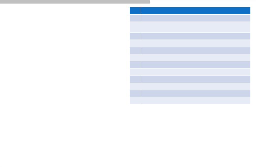
No |
Item |
1.0 |
No Power - PSU |
1.2 |
No Power -u-Com Failure |
1.3 |
No Power - DDCON/LDO |
1.4 |
No Power - Main Device Failure |
1.5 |
No Power - Main Device Replacement |
2.0 |
LED Blinking: 2x (Main power Error) |
2.1 |
LED Blinking: 3x (DC Alert) |
2.2 |
LED Blinking: 3x (Audio Error) |
2.3 |
LED Blinking: 4x (LD Voltage Error) |
2.4 |
LED Blinking: 5x (Panel Communication Error) |
2.5 |
LED Blinking: 6x (Backlight Error) |
2.6 |
LED Blinking: 7x (Temperature Error) |
3.0 |
No Sound |
3.1 |
No Sound: Audio (For all models) |
3.3 |
Main Board Power Off Checking (for Main SP Lch & |
Rch) |
|
3.4 |
Main Board Power On Checking (for Main SP Lch & |
Rch) |
|
3.5 |
No Sound: HP / Lineout Only |
3.6 |
No Sound: SCART OUT Audio |
3.7 |
No Sound: Tuner |
3.8 |
No Sound: HDMI |
No |
Item |
4.0 |
No Picture: All models |
4.1 |
No Picture: VIDEO Component/CVBS/SCART Analog |
Signal Path |
|
4.2 |
No Picture: VIDEO |
4.3 |
No Picture: Component/SCART |
4.4 |
No Picture: Tuner |
4.5 |
No Picture: HDMI |
5.0 |
Side Buttons Malfunction |
5.1 |
IR Remote Commander Malfunction |
5.2 |
Light Sensor Error |
6.0 |
Network Malfunction: Ethernet (Wired) |
6.2 |
Troubleshoot flow for Wireless Network malfunction |
6.3 |
Troubleshoot flow for Bluetooth malfunction (3D, TPR) |
14

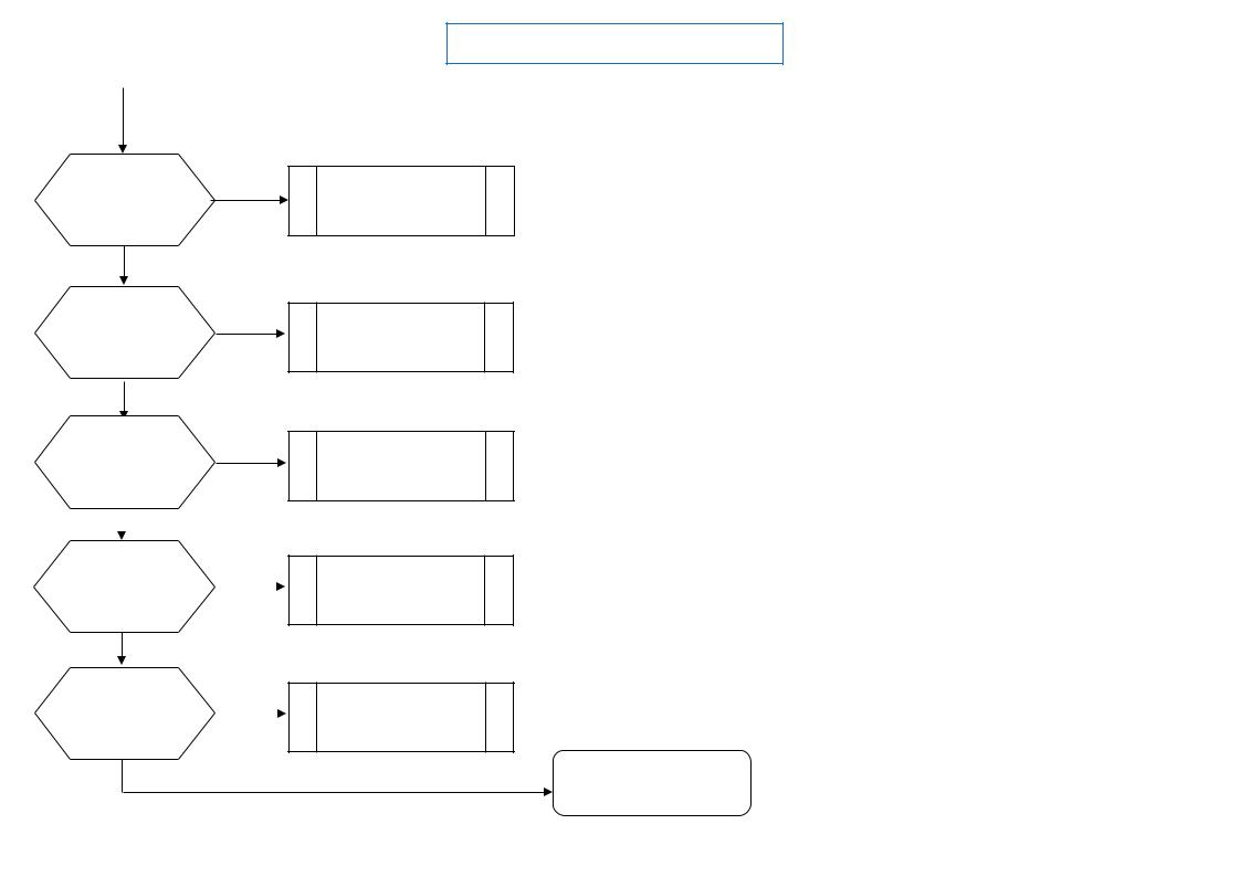
1.0 No Power – PSU
15

1 No Power
BFM Board Model
|
|
|
|
|
|
|
|
|
|
|
with G* board |
|
|
|
with AC-ADP |
|
|
|
|
||
|
No Power |
|
|
|
No Power |
|
|
|
|
|
Check STBY 3.3V |
|
Replace |
NG |
Check 19.5V |
|
Replace |
NG |
|
||
|
C413 |
NG |
|
C401 |
NG |
LD Board or |
||||
|
Between G* Board to |
G* Board |
|
Between LD Board to |
|
|||||
|
near CN400 |
|
near CN400 |
|
|
AC Adaptor |
||||
|
|
|
|
|||||||
|
|
BFM Board Harness |
|
|
BFM Board Harness |
|
||||
|
on BFM board |
|
|
on BFM board |
|
|
|
|||
|
|
OK |
|
|
OK |
|
|
|||
|
|
|
|
|
|
|
|
|
||
|
OK |
|
|
|
OK |
|
|
|
|
|
|
|
|
Harness |
|
|
|
|
Harness |
|
|
BFM Board |
BFM Board |
u-Com Failure |
u-Com Failure |
DDCON/LDO |
DDCON/LDO |
Main Device Failure |
Main Device Failure |
16

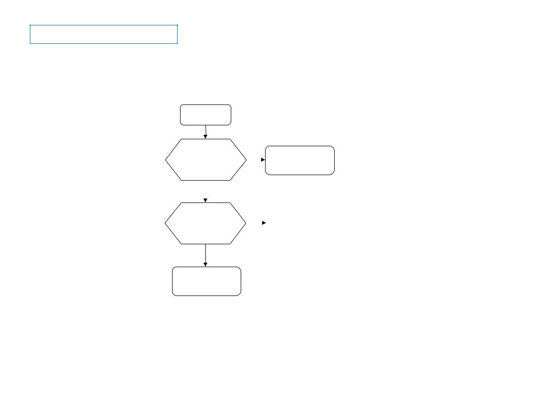
1 No Power
BM2/DPA Board Model
with G* board
No Power
Check STBY 3.3V
C497 near CN401 on DPA board
OK
Check STBY 3.3V
C402 near CN400 on BM2 board
OK
BM2 Board
NG
NG
Replace Between G* Board to DPA Board Harness
OK 
Harness
Replace Between DPA Board to
BM2 Board Harness OK 
Harness
u-Com Failure
DDCON/LDO
Main Device Failure
NG
G* Board
NG |
R407, R408 |
|
|
|
on DPA Board |
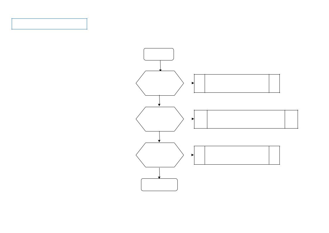
with AC-ADP
No Power
Check 24V
C485 near CN401 on DPA board
OK
Check STBY 3.3V
C402 near CN400 on BM2 board
OK
BM2 Board
NG
NG
Replace Between LD Board to DPA Board Harness
OK 
Harness
Replace Between DPA Board to
BM2 Board Harness OK 
Harness
u-Com Failure
DDCON/LDO
Main Device Failure
NG |
LD Board |
|
|
|
or |
|
AC Adaptor |
NG |
IC408 |
|
|
|
on DPA Board |
17

1.2 No Power – μ-Com Failure
18
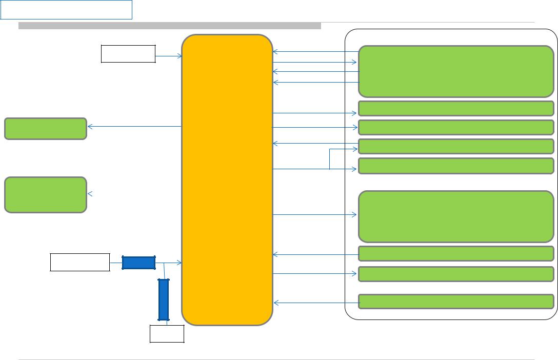
1.2 No Power u-com Failure
BFM Board Model
+3.3V_STBY
BL_ON
G-Board or LD
G-Board or LD |
POWER_ON |
or IC409 |
|
|
+12V_REG |
R430 |
R437 |
GND
P-on u-com control signal path summary |
B-Board |
#pin1
Vdd Ucom supply voltage
#pin18
#pin19IC401
#pin7
MAIN_VC C
ADC port
com u on-P -
#pin2
#pin12
#pin5
#pin10
#pin16
#pin1
1
#pin9
#pin1
3
#pin14
#pin3
#pin15
#pin8
OPWRSB
ORESETB
AC_OFF_INFO
PANEL_PWR_ON
X_SYSTEM_RST
P_ON_VBUS
PGOOD_ 1
P_ON_#1
P_ON_#2
DC_OFF_DET
P_ON_LNB
BL_MUTE
SOC Muffin 2 (IC1000)
Tuner (CN2800)
DDC: +5.0V_VBUS (IC402)
DDC : +1.0V_M2 (IC604)
DDCs : +1.8V_TU (IC405)
DDCs : +5V_MAIN (IC404), +3.3V_MAIN (Q406/Q407)
LDOs: +1.05V_M2_A_1 (IC603),
+1.05V_M2_A_2 (IC606), VCC3IO_EMMC (IC2002)
DC_OFF_DET (IC400)
+12V_LNB (Q408/Q409)
SOC Muffin 2 (IC1000)
19
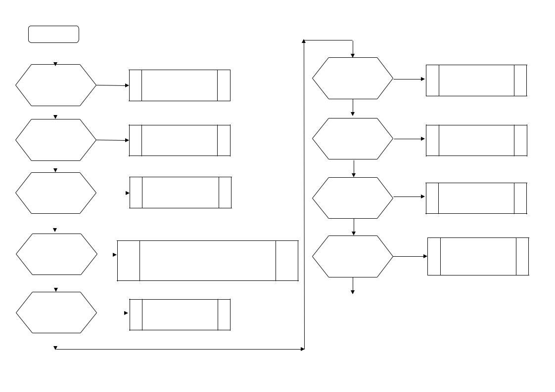
1.2 No Power u-com Failure |
BFM Board Model |
|
||
|
START |
|
|
|
|
|
|
|
|
|
|
|
|
|
|
|
|
|
|
|
|
|
|
|
Check VDD |
no |
|
|||
C419 Voltage. |
|
|
|
||
Is the voltage >3.0V? |
|
|
|
||
|
yes |
|
|
|
|
|
|
|
|
||
|
|
|
|
|
|
Check DC_OFF_DET |
no |
|
|||
C504 Voltage. |
|
|
|
||
Is the voltage >3.0V? |
|
|
|
||
|
yes |
|
|
|
|
|
|
|
|
||
Check OPWRSB |
no |
|
|||
R441 Voltage. |
|
|
|||
|
|
|
|
||
|
|
|
|
||
Is the voltage 0V? |
|
|
|
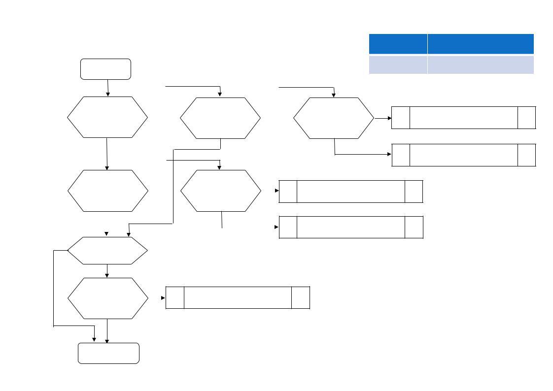
||
|
yes |
|
|
|
|
|
|
|
|
||
|
|
|
|
|
|
Check POWER_ON |
no |
|
|||
P-on ucom #pin19 |
|
||||
|
|
|
|||
|
|
|
|||
Is the voltage >3.0V? |
|
|
|
||
|
yes |
|
|
|
|
|
|
|
|
||
|
|
|
|
|
|
Check P_ON_LNB |
no |
|
|||
P-on ucom #pin15 |
|
||||
|
|
|
|||
|
|
|
|||
Is the voltage >3.0V? |
|
|
|
||
|
yes |
|
|
|
|
|
|
|
|
||
|
|
|
|
|
|
Check +3.3V_STBY
C413, CN400 #24pin
Check DC_OFF_DET
IC400
SOC
Muffin 2 problem
Try AC Off and On after few minutes. If #pin19 keep Low, change IC401.
If #pin19 goes High few seconds and downs to Low, Check +12V_MAIN Line (G board, LD or IC409).
Change IC401
Check MAIN_VCC
no
R437 Voltage. Is the voltage >1.6V?
yes
Check P_ON_VBUS
no
P-on ucom #pin11 is >3.0V?
yes
Check P_ON_#1
no
P-on ucom #pin13 is >3.0V?
yes
Check PGOOD_1
no
R434 Voltage. Is the voltage >3.0V?
Continue next page…
Check +12V_MAIN Line (G board, LD or IC409).
Change IC401
Change IC401
1.3 No POWER - DDCON/LDO
Check 1.0V DDCON (IC604)
And (if it is mounted)
12V DDCON (IC409).
20 |
20 |
|
|
1.2 No Power u-com Failure |
BFM Board Model |
Cont…
yes
Check P_ON_#2 P-on ucom #pin14 Is the voltage >3.0V?
yes
Check ORESETB P-on ucom #pin12 Is the voltage >3.0V?
yes
Check X_SYSTEM_RST P-on ucom #pin16 Is the voltage >3.0V?
yes
If BL_MUTE (R435) is 0V Check BL_ON
P-on ucom #pin18
Is the voltage >3.0V? yes
no
no
no
no
Change IC401
Change IC401
Change IC401
Change IC401
END
Ucom IC401 is working OK
21 |
21 |
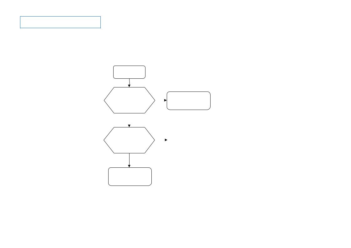
1.2 No Power u-com Failure
BFM Board Model
DC_OFF_DET check
START
Check DC_OFF_DET |
no |
|||||
R420 |
|
|
|
END |
||
|
|
IC400 is working OK |
||||
Is voltage < 3V? |
|
|
||||
|
|
|
|
|
||
|
yes |
|
|
|
|
|
|
|
|
|
|
|
|
|
|
|
|
|
|
|
Check Vdd |
no |
|
|
|
||
|
Change IC400 |
|
||||
C418 |
|
|
||||
|
|
|
|
|||
|
|
|
|
|||
Is voltage < 5V? |
|
|
|
|
|
|
yes
END
IC400 is working OK
22 |
22 |
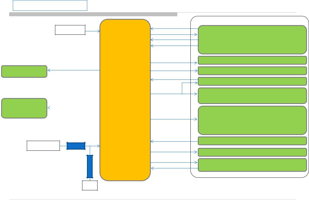
1.2 No Power u-com Failure
BM2/DPA Board Model |
P-on u-com control signal path summary |
|
+3.3V_STBY
BL_ON
G-Board or LD
G-Board or LD |
POWER_ON |
or IC403 on DPA |
|
|
+12V_REG |
R430 |
R437 |
GND
#pin1
Vdd Ucom supply voltage
#pin18
#pin19IC401
#pin7
MAIN_VC C
ADC port
com u on-P -
#pin2
#pin12
#pin5
#pin10
#pin16
#pin1
1
#pin9
#pin1
3
#pin14
#pin3
#pin15
#pin17
#pin8
OPWRSB
ORESETB
AC_OFF_INFO
PANEL_PWR_ON
X_SYSTEM_RST
P_ON_VBUS
PGOOD_ 1
P_ON_#1
P_ON_#2
DC_OFF_DET
P_ON_LNB
X_BE_RST
X_LED_MUT
E
BM2 or DPA Board
SOC Muffin 2 (IC1000)
Tuner (TU2801 , TU2802, TU2803)
DDC: +5.0V_VBUS (IC402)
DDC : +1.0V_M2 (IC604)
DDCs : +1.8V_TU (IC405), +1.1V_TU_SKP (IC406)
DDCs : +5V_MAIN (IC404), +3.3V_MAIN
+1.0V_BE (IC4003/DPA) (IC409/DPA),
+1.5V_BE (IC4001/DPA) , +1.1V_BE (IC4002/DPA)
LDOs: +1.05V_M2_A_1 (IC603),
DC_OFF_DET (IC400)
+12V_LNB (Q408/409)
SOC BE (IC4000/DPA)
23
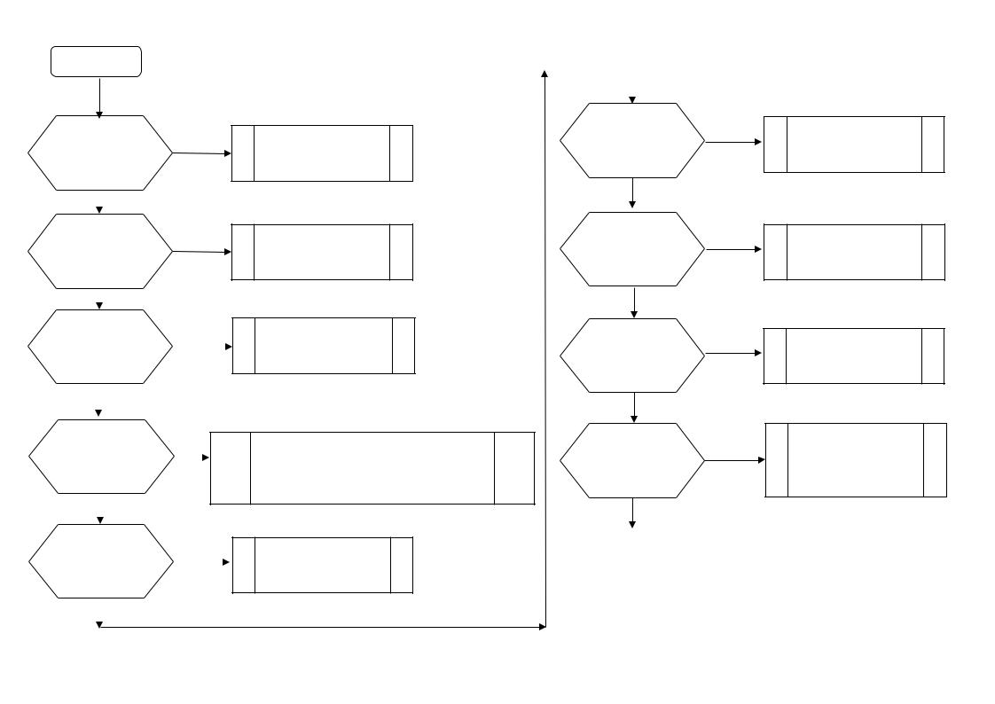
1.2 No Power u-com Failure |
BM2/DPA Board Model |
|
||
START |
|
|
|
|
|
|
|
|
|
|
|
|
|
|
|
|
|
|
|
|
|
|
|
|
Check VDD |
no |
|
|||
C419 Voltage. |
|
|
|
||
Is the voltage >3.0V? |
|
|
|
||
|
yes |
|
|
|
|
|
|
|
|
||
|
|
|
|
|
|
Check DC_OFF_DET |
no |
|
|||
C481 Voltage. |
|
|
|
||
Is the voltage >3.0V? |
|
|
|
||
|
yes |
|
|
|
|
|
|
|
|
||
Check OPWRSB |
no |
|
|||
R441 Voltage. |
|
|
|||
|
|
|
|
||
|
|
|
|
||
Is the voltage 0V? |
|
|
|
||
|
yes |
|
|
|
|
|
|
|
|
||
|
|
|
|
|
|
Check POWER_ON |
no |
|
|||
P-on ucom #pin19 |
|
||||
|
|
|
|||
|
|
|
|||
Is the voltage >3.0V? |
|
|
|
||
|
yes |
|
|
|
|
|
|
|
|
||
|
|
|
|
|
|
Check P_ON_LNB |
no |
|
|||
P-on ucom #pin15 |
|
||||
|
|
|
|||
|
|
|
|||
Is the voltage >3.0V? |
|
|
|
||
|
yes |
|
|
|
|
|
|
|
|
||
|
|
|
|
|
|
Check +3.3V_STBY
C402, CN400 #1pin
Check DC_OFF_DET
IC400
SOC
Muffin 2 problem
Try AC Off and On after few minutes. If #pin19 keep Low, change IC401.
If #pin19 goes High few seconds and downs to Low, Check +12V_MAIN Line (G board or IC403 on DPA).
Change IC401
Check MAIN_VCC
no
R437 Voltage. Is the voltage >1.6V?
yes
Check P_ON_VBUS
no
P-on ucom #pin11 is >3.0V?
yes
Check P_ON_#1
no
P-on ucom #pin13 is >3.0V?
yes
Check PGOOD_1
no
R434 Voltage. Is the voltage >3.0V?
Continue next page…
Check +12V_MAIN Line
(G board or IC403 on DPA).
Change IC401
Change IC401
1.3 No POWER - DDCON/LDO Check 1.0V DDCON (IC604) and (only for AC-ADP model) 12V DDCON (IC403 on DPA).
24 |
24 |
1.2 No Power u-com Failure
Cont… yes
Check P_ON_#2
no
P-on ucom #pin14 Is the voltage >3.0V?
yes
Check ORESETB
no
P-on ucom #pin12 Is the voltage >3.0V?
yes
Check X_SYSTEM_RST
no
P-on ucom #pin16 Is the voltage >3.0V?
|
yes |
|
|
|
|
|
|
If PANEL_PWER_ON (R433) is 0V |
|
||
Check X_BE_RST |
no |
||
|
|
|
|
P-on ucom #pin17 |
|
||
Is the voltage >3.0V? |
|
||
|
yes |
|
|
If BL_MUTE (R435) is 0V |
|
||
Check BL_ON |
no |
||
|
|
|
|
P-on ucom #pin18 |
|
||
Is the voltage >3.0V? |
|
||
|
yes |
|
|
Change IC401
Change IC401
Change IC401
Change IC401
Change IC401
BM2/DPA Board Model
END
Ucom IC401 is working OK
25 |
25 |
1.2 No Power u-com Failure
BM2/DPA Board Model
DC_OFF_DET check
START
Check DC_OFF_DET |
no |
|||||
R420 |
|
|
|
END |
||
|
|
IC400 is working OK |
||||
Is voltage < 3V? |
|
|
||||
|
|
|
|
|
||
|
yes |
|
|
|
|
|
|
|
|
|
|
|
|
|
|
|
|
|
|
|
Check Vdd |
no |
|
|
|
||
|
Change IC400 |
|
||||
C418 |
|
|
||||
|
|
|
|
|||
|
|
|
|
|||
Is voltage < 5V? |
|
|
|
|
|
|
yes
END
IC400 is working OK
26 |
26 |

1.3 No Power DDCON/LDO
27 |
27 |

1.3 No Power DDCON/LDO
BFM Board Model
Check item summary
IC Ref |
Voltage supply |
Output ref. |
Enable pin |
Enable source |
Fuse |
Vcc ref. |
|
|
|
|
|
|
|
|
|
IC402 |
+5.0V_VBUS |
C430 |
R455 |
P-on ucom IC401 #pin11 |
F400 |
C423 |
|
|
|
|
|
|
|
|
|
IC403 |
+3.3V_DDC_OUT |
C444 |
R467 |
R464 (19.5 or 12.5V) |
F401 |
C436 |
|
|
|
|
|
|
|
|
|
IC404 |
+5V_MAIN |
C456 |
IC404 #PIN1 |
P-on ucom IC401 #pin14 |
F402 |
C453 |
|
|
|
|
|
|
|
|
|
IC405 |
+1.8V_TU |
C463 |
IC405 #PIN5 |
P-on ucom IC401 #pin13 |
F403 |
C461 |
|
|
|
|
|
|
|
|
|
IC409 |
+12V_MAIN (AEP/J AC-ADP |
C483 |
R513 |
P-on ucom IC401 #pin19 |
F404 |
C476 |
|
only) |
|||||||
|
|
|
|
|
|
||
|
|
|
|
|
|
|
|
IC601 |
+1.5V_DDR |
C609 |
C605 |
R603 (3.3V or 5V) |
- |
C602 |
|
|
|
|
|
|
|
|
|
IC602 |
+1.05V_M2_STBY |
C611 |
R612 |
C610 (+3.3V _STBY) |
- |
C610 |
|
|
|
|
|
|
|
|
|
IC603 |
+1.05V_M2_A_1 |
C613 |
R619 |
P-on ucom IC401 #pin14 |
- |
C612 |
|
|
|
|
|
|
|
|
|
IC604 |
+1.0V_M2 |
C625 |
R623 |
P-on ucom IC401 #pin13 |
F600 |
C618 |
|
|
|
|
|
|
|
|
|
IC605 |
+1.05V_M2_ST_ET |
C631 |
R613 |
M2 IC1000 #AP34 |
- |
C630 |
|
|
|
|
|
|
|
|
|
IC606 |
+1.05V_M2_A_2 |
C633 |
R633 |
P-on ucom IC401 #pin14 |
- |
C632 |
|
|
|
|
|
|
|
|
28 |
28 |
1.3 No Power DDCON/LDO
BFM Board Model
IC Ref |
Voltage supply |
|
|
IC402 |
+5.0V_VBUS |
|
|
IC403 |
+3.3V_DDC_OUT |
|
|
IC404 |
+5V_MAIN |
|
|
IC405 |
+1.8V_TU |
|
|
IC409 |
+12V_MAIN (AEP/J AC-ADP only) |
|
|
IC604 |
+1.0V_M2 |
|
|
DDCONs check
START
Check fuse |
no |
||
F4xx or F6xx |
|||
|
|
||
|
|
||
Is fuse OK? |
|
|
|
yes |
|
|
|
Check Vcc voltage |
no |
||
C4xx or C6xx |
|||
|
|
||
|
|
||
Is voltage >12.0V? |
|
|
|
yes |
|
|
|
Check Enable pin |
no |
||
voltage |
|||
|
|
||
|
|
||
Is voltage >2.5V? |
|
|
|
yes |
|
|
|
Change DDCON IC |
|
|
|
Please refer page-28 for Ref number.
Change Fuse
Check POWER_ON P-on ucom #pin19 (Refer 1.2 No Power U-Com Failure)
1.2 No Power U-Com Failure or
Enable source
29 |
29 |
1.3 No Power DDCON/LDO |
BFM Board Model |
DDCON check
START
Check IC404Vcc voltage |
no |
|
C454 |
||
|
||
|
||
Is voltage >12V? |
|
yes
Check Vcc voltage |
no |
|
C602 |
||
|
||
|
||
Is voltage >4V? |
|
 yes
yes
no
Is IC600 mounted?
yes
Check Enable |
no |
||
IC600 #pin1 |
|||
|
|
||
|
|
||
Is voltage >2.5V? |
|
|
|
yes
Change DDCON
IC601
Check Vcc voltage |
no |
|
C602 |
||
|
||
|
||
Is voltage >3V? |
|
yes
Check |
no |
|
|
|
|
D601 |
|
|
|
||
Is diode ? |
|
|
|
yes |
|
|
|
|
Change IC600
IC Ref |
Voltage supply |
IC601 |
+1.5V_DDR |
Check |
no |
|
|
D600 |
Change D600 |
Is diode ? |
|
yes |
Check +3.3V_STBY. |
|
|
|
G board or IC403 |
Change D601 |
|
Check +5V_MAIN DDCON (IC404)
30 |
30 |
Loading...