


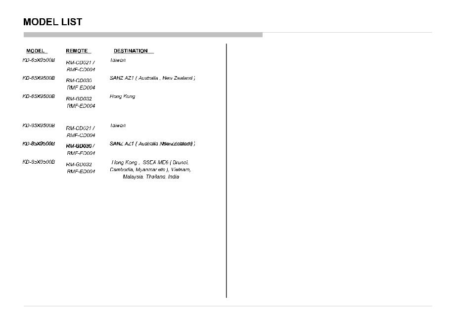
KD-65/85X9500B |
3 |
|
These servicing instructions are for use by qualified service personnel only.
To reduce the risk of electric shock, do not perform any servicing other than that contained in the operating instructions unless you are qualified to do so.
An isolation transformer should be used during any service to avoid possible shock hazard, because of live chassis.
The chassis of this receiver is directly connected to the ac power line.
Be sure to follow these guidelines to protect your property and avoid causing serious injury.
•Carry the TV with an adequate number of people; larger size TVs require two or more people.
•Correctthanddplacementtwhile carrying thethTVis very importanttfortsafetyfandt toavoidt damagesid.
Components identified by shading and ! mark on the schematic diagrams, exploded views, and in the parts list are critical for safe operation. Replace these components with Sony parts whose part numbers appear as shown in this manual or in supplements published by Sony. Circuit adjustments that are critical for safe operation are identified in this manual. Follow these procedures whenever critical components are replaced or improper operation is suspected.
•Danger of explosion if battery is incorrectly replaced. Replace only with the same or equivalent type.
•Outer case broken battery shouldldnot contactt t tto water.
KD-65/85X9500B |
4 |
|
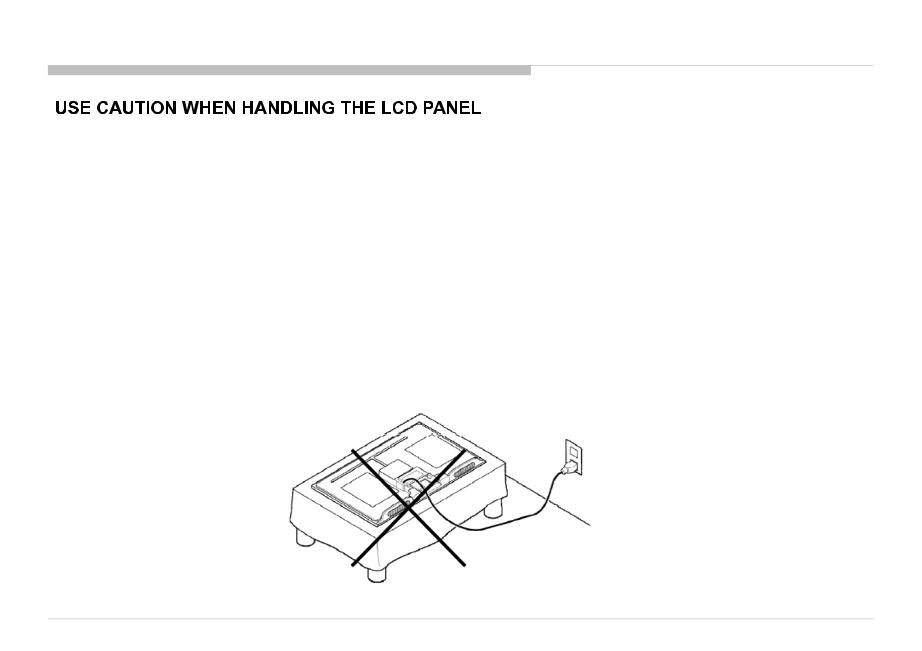
WARNINGS AND CAUTIONS
When repairing the LCD panel, be sure you are grounded by using a wrist band.
When repairing the LCD panel on the wall,allthetheLCDpanelmuststbebesecuredusingthe44mountingnting holesononthetherearrearcocover.
1)Do not press on the panel or frame edge to avoid the risk of electric shock.
2)Do not scratch or press on the panel with any sharp objects.
3)Do not leave the module in high temperatures or in areas of high humidity for an extended period of time.
4)Do not expose the LCD panel to direct sunlight.
5)Avoid contact with water. It may cause a short circuit within the module.
6)Disconnect the AC power when replacing the backlight (CCFL) or inverter circuit. (High voltage occurs at the inverter circuit at 650Vrms.)
7)Always clean the LCD panel with a soft cloth material.
8)Use care when handlinggthe wires or connectors of the inverter circuit. Damagingtheg wires may causey a short.
9)Protect the panel from ESD to avoid damaging the electronic circuit (C-MOS).
10)It is recommended not to exceed 1 hour of Power-On nor Burn-in period with LCD panel face down condition, in repair activity.
KD-65/85X9500B |
5 |
|
After correcting the original service problem, perform the following safety checks before releasing the set to the customer:
1.Check the area of your repair for unsoldered or poorly soldered connections. Check the entire board surface for solder splashes and bridges.
2.Check the interboard wiring to ensure that no wires are “pinched” or touching high-wattage resistors.
3.Check that all control knobs, shields, covers, ground straps, and mounting hardware have been replaced. Be absolutely certain that you have replaced all the insulators.
4.Look for unauthorized replacement parts, particularly transistors, that were installed during a previous repair. Point them out to the customer and recommend their replacement.
5.Look for parts which, though functioning, show obvious signs of deterioration. Point them out to the customer and recommend their replacement.
6.Check the line cords for cracks and abrasion. Recommend the replacement of any such line cord to the customer.
7.Check the antenna terminals, metal trim, “metallized” knobs, screws, and all other exposed metal parts for AC leakage. Check leakage as described below.
8.For safety reasons, repairing the Power board and/or Inverter board is prohibited.
KD-65/85X9500B |
6 |
|

SAFETY CHECK-OUT
KD-65/85X9500B |
7 |
|
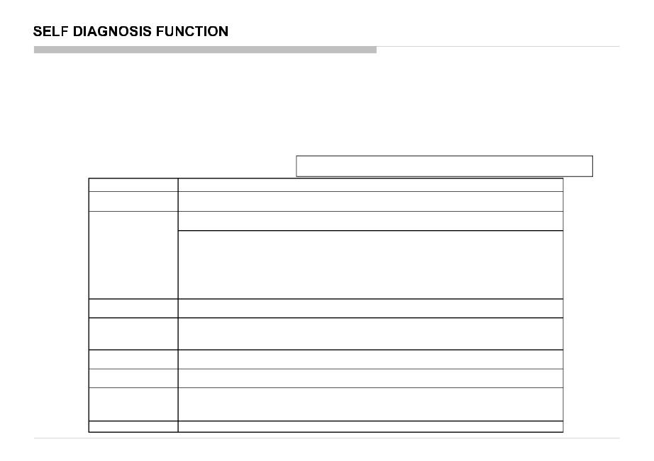
The units in this manual contain a self-diagnostic function. If an error occurs, the Smart Core Red LED will automatically begin to flash. The number of times the LED flashes translates to a probable source of the problem.
A definition of the Smart Core Red LED flash indicators is listed in the instruction manual for the user’s knowledge and reference.
If an error symptom cannot be reproduced, the remote commander can be used to review the failure occurrence data stored in memory to reveal past problems and how often these problems occur.
DIAGNOSTIC TEST INDICATORS
When an error occurs, the Smart Core Red LED will flash a set number of times to indicate the possible cause of the problem.
If there is more than one error, the LED will identify the first of the problem areas. |
|
||
Result for all of the following diagnostic items are displayed on screen. |
<G>: Power supply board, <B>: Main board, <T>: Tcon board, <L>: LED driver (LD) board , |
||
|
|
||
If the screen displays a “0”, no error has occurred . |
<P>: Panel module , <S>: Speaker , <A>: Power Adapter, <U> Tuner board |
||
RED LED blinking count |
|
Detection Items |
|
2x |
<G/B> Main 12V failure [MAIN_POWE] |
|
|
* This failure is not saved. |
|
||
|
|
||
|
<B> Main 5.0/3.3/1.8/1.0 failure [DC_ALERT] |
|
|
|
* 5.0/1.0V failures are not saved. |
|
|
|
<B/S> Audio amp. protection / Audio amp. I2C NACK [AUD_ERR] |
||
|
<B> HDMI equalizer/switch I2C NACK [HDMI_EQ/HDMI_EQ2/HDMI_EQ3] * There is Temp. sensor on the same I2C bus |
||
3x |
<B/U> Tuner or demodulator I2C NACK [TU_DEMOD] |
|
|
<B/U> AFE device I2C NACK [AFE_I2C] |
|
||
|
|
||
|
<B/U> AFE device SPI NACK [AFE_SPI] * only for AEP,CH |
|
|
|
<B> V-by-One lock monitoring between CXD4746 and NT72324[SC_OUT_ERR] |
||
|
<B> CXD4746 I2C NACK and V-by-One lock monitoring between CXD4746 and Ayu2[SC_ERR] |
||
|
<B> FW initialization error and I2C NACK for NT72324[FRCD_I2C] |
||
4x |
<L/P> LED driver failure [LD_ERR] |
|
|
<L/P> LED voltage error [VLED] |
|
||
|
|
||
|
<B/T>Tcon device initialization failure detection [TCON_ERR] |
||
5x |
<B/T>Tcon device I2C communication error detection [TCON_ERR] |
||
<P/T/G/B> Panel ID EEPROM I2C NACK (Also panel power failure is a suspect) [P_ID_ERR] |
|||
|
|||
|
*PCON_ERR and TG_ERR is not used. |
|
|
6x |
<G/P/B> Backlight failure [BACKLIGHT] |
|
|
<G/T/P/B> Backlight converter OVP [BACKLIGHT] |
|
||
|
|
||
7x |
Over temperature protection [TEMP_ERR] |
|
|
<B> Temp. sensor I2C NACK [TEMP_ERR] * There is HDMI Eq on the same I2C bus. |
|||
|
|||
|
Software Error (Also the main boardʼs memory or CAM module is a suspect) |
||
8x |
<B> CXD4754 device error and WDT detection [LYON_ERR] |
||
*EvenififdetectingCXD4745Deviceerrror,thesetdoesnotgogototosafetyshutdown(onlywhenuserusesCXD4754function,thesetreboots)ts) |
|||
|
|||
|
and not flash LED, only records error logs. |
|
|
9x |
<U>Tuner board error [TU_BOARD] |
|
|
KD-65/85X9500B |
8 |
|
[SELF DIAGNOSTIC SCREEN DISPLAY]
Smart Core
Red LED
blinkinggcount
|
Error item name |
*Following error is invalid in RB2. |
||
|
|
|
FAN_ERR |
|
|
|
EMIT _ ERR |
|
|
|
|
TCON _ ERR |
|
|
SELF CHECK |
|
|
|
|
002 MAIN_POWE |
------------Error------------ |
------------ Error |
00 |
Error |
003 AFE_I2C ------------ |
00 |
|||
003 DC_ALERT |
------------timestam------------ ------------ |
timestam |
00 |
timestam |
003 AUD_PROT |
------------p for last------------ ------------ |
p for |
00 |
p for 3rd |
003 HDMI_EQ ------------ |
recorded------------ ------------ |
second |
00 |
last |
003 TU_DEMOD |
------------error------------ ------------ |
last |
00 |
recorded |
_ |
003 AFE SPI |
recorded r |
00 |
error |
------------ ------------ ------------ |
||||
003 SC_OUTERR |
|
error |
00 |
error |
------------ ------------ ------------ |
|
|||
003 SC_ERR ------------ |
------------ ------------ |
00 |
|
|
003 FRCD_I2C |
------------ ------------ ------------ |
|
00 |
|
003 HDMI_EQ2 |
------------ ------------ ------------ |
|
00 |
|
|
003 HDMI_EQ3 |
|
00 |
|
|
------------ ------------ ------------ |
|
|
|
003 LYON_ERR ------------ |
Format------------of error ------------timestamps00 |
|
||
004 VLED ------------ |
YYMMDDhhmmss------------ ------------(in UTC)00 |
|
||
004 LD_ERR |
004 LD ERR |
|
00 |
00 |
------------Example:------------Example:------------ |
||||
005 TCON_ERR |
------------ ------------ ------------ |
|
00 |
|
005 P_ID_ERR ------------ |
120823132523------------ -------------> Aug 23002012 13:25:23 UTC |
|||
005 PCON_ERR |
* Only when time is set, an error timestamp is saved. |
|||
------------ ------------ ------------ |
|
00 |
|
|
|
005 TG_ERR |
|
00 |
|
|
------------ ------------ ------------ |
|
|
|
006 BACKLITE |
------------ ------------ ------------ |
|
00 |
|
007 TEMP_ERR |
120823132523 ------------ ------------ |
|
01 |
|
|
007 FAN_ERR |
|
00 |
|
|
------------ ------------ ------------ |
|
|
|
008 VPC_WDT |
------------ ------------ ------------ |
|
00 |
|
008 MEPS_WDT |
------------ ------------ ------------ |
|
00 |
|
008 HOST_WDT |
------------ ------------ ------------ |
|
00 |
|
008 STBY_WDT |
------------ ------------ ------------ |
|
00 |
|
008 AFE_WDT ------------ |
------------ ------------ |
|
00 |
|
009 TU_BOARD |
------------ ------------ ------------ |
|
00 |
|
00081-000671-00088 00000000000000000570-00000000000000000132
SELF DIAGNOSIS FUNCTION
|
Model Name |
|
:KDL-RB2T |
|||
|
Serial Number |
|
:1000162 |
|||
MAC address |
Package Number |
:PKG0.410EUA |
||||
Device ID |
|
:B0:00:02:4D:72:88 |
||||
of Wi-Fi USB |
|
|||||
Wired Mac |
Wired Mac |
|
||||
|
|
:D8:D4:3C:A2:EE:9F |
||||
dongle*1. |
|
|
|
|
|
:D8:D4:3C:A2:EE:9F |
Wireless Mac |
:34:23:87:d4:48:a4 |
|||||
|
USB dongle |
|
:N/A |
|||
|
<MAIN> |
|
|
|
|
<EXT> |
|
DM0.410EUA |
|
|
|
WF:3.5.3.9999 |
|
|
WF0.300W00AA |
|
|
WF:-------- |
||
|
DF5.137W00AA |
|
|
BT: |
||
|
YM1.224W00AA |
|
|
2.1.14.471 |
||
|
M5.503C |
|
|
|
|
EFR:03.01.01.18 |
|
(DM0.390EUA) |
|
|
|
||
Error count |
DD0.370W00AA |
|
|
<FS> |
||
PK0.370W00AA |
|
|
SCF:50.10 |
|||
|
AM0.410WW |
|
|
|
ROF:----------------- |
|
|
MID:2411AB19 |
|
|
|
|
|
|
PIDPID:0E0E042042040 |
|
|
|
||
|
PNL:YD4S550LTU010 |
|
||||
Main CPU |
External module |
|
information |
||
information |
||
|
*1
1.When no Wi-Fi USB dongle is connected, NA is displayed.
2.If you insert/disconnect Wi-Fi USB Dongle during Self Diagnosis Display, press <1> -> <4> on remote commander to refresh Mac address displayed on “USB dongle”.
-Alternatively, you can re-display Self Diagnosis Display to update the information.
Panel operation time by hour
Panel Operation Time is recorded every 30 min, but Total Operation Time is recorded every 1 hr. Therefore, the panel op. time might become larger than the total op. time.
Count of writing to NAND device: As vfat partition– As ext4 partition
Boot count
Total operation time by hour
KD-65/85X9500B |
9 |
|
SELF DIAGNOSIS FUNCTION
SELF-DIAGNOSTIC SCREEN DISPLAY
For errors with symptoms such as “power sometimes shuts off” or “screen sometimes goes out” that cannot be confirmed, it is possible to bring up past occurrences of failure for confirmation on the screen:
S |
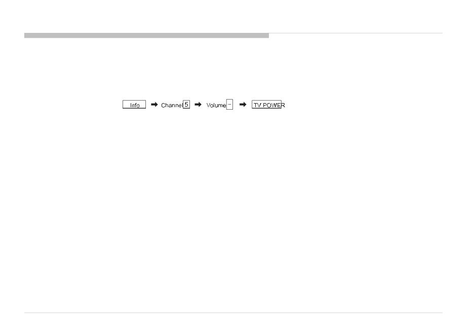
[To Bring Up Screen Test] |
In standby mode, press buttons on the remote commander sequentially in rapid succession as shown below:
*
* : Note that this differs from entering the service mode (volume +)
Since the diagnostic results displayed on the screen are not automatically cleared,alwayschecktheselfdiagnosticscreen.
After you have completed the repairs, clear the result display to “0”.
Clearing the Self Check Diagnostic List
1.Error history :
2.Panel operation time :
Press the Channel 8 => Channel 0 . Press the Channel 7 => Channel 0 .
Exiting the Self-diagnostic screen
To exit the Self Diagnostic screen, turn off the power to the TV by pressing the POWER button on the remote or the POWER button on the TV.
KD-65/85X9500B |
10 |
|
• There are clutch in the yellow frame[ |
]. Therefore please be careful in the case of the disassembly or assembly of parts. |
KD-65/85X9500B |
11 |
|
DISASSEMBLY
1-1-1. STAND
2 Screws (SCREW, +PSW M5X16) P/N: 2-580-608-01 |
2 Screws (SCREW, +PSW M5X16) P/N: 2-580-608-01 |
1
2
STAND,RIGHT (2L MIA) |
STAND,LEFT (2L MIA) |
|
P/N: 4-486-545-02 |
||
P/N: 4-486-550-02 |
||
|
KD-65/85X9500B |
12 |
|

DISASSEMBLY
1-1-2. CAMERA MODULE EXTERNAL TYPED
1
Screw (SCREW +PSW M4X10) P/N: 4-159-298-01
2 |
CAMERA MODULE |
|
EXTERNAL TYPED |
||
|
KD-65/85X9500B |
13 |
|

DISASSEMBLY
1-1-3. COVER, TERMINAL SIDE
2
1 |
3 |
COVER, TERMINAL SIDE
KD-65/85X9500B |
14 |
|

DISASSEMBLY
1-1-4. COVER, TERMINAL REAR
2
1 |
3 |
COVER, TERMINAL REAR
KD-65/85X9500B |
15 |
|

DISASSEMBLY
1-1-5. LABEL, REAR TERMINAL/LABEL, SIDE TERMINAL
LABEL, SIDE TERMINAL
LABEL,REARTERMINALINAL
KD-65/85X9500B |
16 |
|

DISASSEMBLY
1-1-6. REAR COVER (2L MIA) A |
2 |
1
3
REAR COVER (2L MIA) A
16 Screws (SCREW, +PSW M3X6 STEP) P/N: 4-457-815-02
CATCH, HOOK N
1 Screw (SCREW, +PSW M4X10) P/N: 4-159-298-01
3Screws (SCREW, +BVTP, 4X12 TYPE2 IT-3) P/N:)2-580-639-01
4Screws (SCREW, ORNAMENTAL M6X12) P/N: 4-268-126-02
KD-65/85X9500B |
17 |
|

DISASSEMBLY
1-1-7. TAPE
TAPE
TAPE |
TAPE |
TAPE
KD-65/85X9500B |
18 |
|

DISASSEMBLY
1-1-8. WIRE DRESSING
KD-65/85X9500B |
19 |
|

DISASSEMBLY
1-1-9. TAPE
TAPE
TAPE
KD-65/85X9500B |
20 |
|

DISASSEMBLY
1-1-10. TAPE
TAPE
TAPE
KD-65/85X9500B |
21 |
|
DISASSEMBLY
1-1-11. WIRE DRESSING
KD-65/85X9500B |
22 |
|

DISASSEMBLY
1-1-12. WIRE DRESSING
KD-65/85X9500B |
23 |
|

DISASSEMBLY
2
1-1-13. AC INLET ASSY
3
1
4 |
AC INLET ASSY |
Screw (SCREW, +PSW M3X6 W12) P/N: 4-256-393-11
KD-65/85X9500B |
24 |
|

DISASSEMBLY
1-1-14. AC INLET
1 |
2 |
BRACKET, AC INLET |
AC INLET
2 Screws (SCREW (+PSW) (M3X6)) P/N: 2-990-421-41
KD-65/85X9500B |
25 |
|

DISASSEMBLY
1-1-15. USB ASSY
2
1
USB ASSY
3
KD-65/85X9500B |
26 |
|
DISASSEMBLY
1-1-16. USB HOLDER, CABLE WITH CONNECTOR (USB) and BRACKET, TOP (MIA)
2
USB HOLDER
CABLE WITH CONNECTOR (USB)
1 |
3 |
BRACKET, TOP (MIA)
KD-65/85X9500B |
27 |
|

DISASSEMBLY
1-1-17. CONNECTOR ASSY
CONNECTOR ASSY, 3P |
CONNECTOR ASSY 20P |
|
P/N: 1-846-714-11 |
||
P/N: 1-910-109-27 |
||
|
KD-65/85X9500B |
28 |
|

DISASSEMBLY
1-1-18. SWF-SPEAKER BOX ASSY
2
1 |
3 |
SWF-SPEAKER BOX ASSY
KD-65/85X9500B |
29 |
|

DISASSEMBLY
1-1-19. SPEAKER BOX ASSY (L)
2
1 |
3 |
SPEAKER BOX ASSY (L)
KD-65/85X9500B |
30 |
|

DISASSEMBLY
1-1-20. SPEAKER BOX ASSY (R)
2
1 |
3 |
SPEAKER BOX ASSY (R)
KD-65/85X9500B |
31 |
|
 Loading...