

Sony HDCAM HDW-F900R, HKDW-702, HDCAM HKDW-703, HDCAM HKDW-902R, HDCAM HKDW-905R Maintenance Manual
...
HD CAMCORDER
HDW-F900R
MAINTENANCE MANUAL
Volume 1 1st Edition (Revised 1)
Serial No. 10001 and Higher : HDW-F900R (SY)
DOWN CONVERTER BOARD
HKDW-702
PICTURE CACHE BOARD
HKDW-703
2-3 PULL-DOWN/DOWN CONVERTER BOARD
HKDW-902R
SLOW SHUTTER/IMAGE INVERTER BOARD
HKDW-905R

HDW-F900R/V1 (E)
! WARNING
This manual is intended for qualified service personnel only.
To reduce the risk of electric shock, fire or injury, do not perform any servicing other than that
contained in the operating instructions unless you are qualified to do so. Refer all servicing to
qualified service personnel.
! WARNUNG
Die Anleitung ist nur für qualifiziertes Fachpersonal bestimmt.
Alle Wartungsarbeiten dürfen nur von qualifiziertem Fachpersonal ausgeführt werden. Um die
Gefahr eines elektrischen Schlages, Feuergefahr und Verletzungen zu vermeiden, sind bei
Wartungsarbeiten strikt die Angaben in der Anleitung zu befolgen. Andere als die angegeben
Wartungsarbeiten dürfen nur von Personen ausgeführt werden, die eine spezielle Befähigung
dazu besitzen.
! AVERTISSEMENT
Ce manual est destiné uniquement aux personnes compétentes en charge de l’entretien. Afin
de réduire les risques de décharge électrique, d’incendie ou de blessure n’effectuer que les
réparations indiquées dans le mode d’emploi à moins d’être qualifié pour en effectuer d’autres.
Pour toute réparation faire appel à une personne compétente uniquement.
HDW-F900R/V1 (E)
1 (P)
Vorsicht!
Explosionsgefahr bei unsachgemäßem Austausch
der Batterie.
Ersatz nur durch denselben oder einen vom
Hersteller empfohlenen ähnlichen Typ. Entsorgung
gebrauchter Batterien nach Angaben des
Herstellers.
ATTENTION
Il y a danger d’explosion s’il y a remplacement
incorrect de la batterie.
Remplacer uniquement avec une batterie du même
type ou d’un type équivalent recommandé par le
constructeur.
Mettre au rebut les batteries usagées conformément
aux instructions du fabricant.
ADVARSEL!
Lithiumbatteri-Eksplosionsfare ved fejlagtig
håndtering.
Udskiftning må kun ske med batteri
af samme fabrikat og type.
Levér det brugte batteri tilbage til leverandøren.
ADVARSEL
Lithiumbatteri - Eksplosjonsfare.
Ved utskifting benyttes kun batteri som
anbefalt av apparatfabrikanten.
Brukt batteri returneres
apparatleverandøren.
VARNING
Explosionsfara vid felaktigt batteribyte.
Använd samma batterityp eller en likvärdig typ
som rekommenderas av apparattillverkaren.
Kassera använt batteri enligt gällande
föreskrifter.
VAROITUS
Paristo voi räjähtää jos se on virheellisesti
asennettu.
Vaihda paristo ainoastaan laitevalmistajan
suosittelemaan tyyppiin.
Hävitä käytetty paristo valmistajan ohjeiden
mukaisesti.
CAUTION
Danger of explosion if battery is incorrectly replaced.
Replace only with the same or equivalent type
recommended by the manufacturer.
Dispose of used batteries according to the
manufacturer’s instructions.

HDW-F900R/V1 (E)
For the customers in the Netherlands
Voor de klanten in Nederland
Hoe u de batterijen moet verwijderen, leest u in de tekst
van deze handleiding.
Gooi de batterij niet weg maar lever deze in als klein
chemisch afval (KCA).
Für Kunden in Deutschland
Entsorgungshinweis: Bitte werfen Sie nur entladene
Batterien in die Sammelboxen beim Handel oder den
Kommunen. Entladen sind Batterien in der Regel dann,
wenn das Gerät abschaltet und signalisiert “Batterie
leer” oder nach längerer Gebrauchsdauer der Batterien
“nicht mehr einwandfrei funktioniert”. Um
sicherzugehen, kleben Sie die Batteriepole z.B. mit
einem Klebestreifen ab oder geben Sie die Batterien
einzeln in einen Plastikbeutel.
For the customers in the U.S.A. and Canada
RECYCLING LITHIUM-ION BATTERIES
Lithium-Ion batteries are recyclable.
You can help preserve our environment
by returning your used rechargeable
batteries to the collection and recycling
location nearest you.
For more information regarding recycling of rechargeable batteries, call toll free
1-800-822-8837, or visit http://www.rbrc.org/
Caution: Do not handle damaged or leaking Lithium-Ion
batteries.
2 (P)

1
HDW-F900R/V1 (E)
Table of Contents
Manual Structure
Purpose of this manual ................................................................. 6
Related manuals ........................................................................... 6
1. Service Overview
1-1. Locations of Main Parts and Circuit Configuration .......1-1
1-1-1. Circuit Configuration and Locations of
the Printed Wiring Boards .....................................1-1
1-1-2. Locations of Main Mechanical Parts ..................... 1-4
1-1-3. Functions and Locations of Sensors ......................1-6
1-2. Matching Connectors ......................................................1-8
1-3. Signal Inputs and Outputs ............................................... 1-8
1-4. Removing and Reinstalling the Outside Panel
Assembly ...................................................................... 1-11
1-5. Opening and Closing the Inside Panel Assembly .........1-12
1-6. Removing and Reinstalling the Connector Box ........... 1-13
1-7. Removing and Reinstalling the Plug-in Boards ............ 1-14
1-7-1. DCP Board Assembly .........................................1-14
1-7-2. DVP Board Assembly ......................................... 1-16
1-8. Removing and Reinstalling the Flexible
Card Wires ....................................................................1-18
1-9. Removing and Reinstalling the Cassette
Compartment ................................................................1-19
1-10. On-Board Switch/Slit Land Description ....................... 1-22
1-10-1. AT-172 Board ..................................................... 1-22
1-10-2. EQ-88G Board ..................................................... 1-23
1-10-3. FP-152 Board ...................................................... 1-24
1-10-4. MDC-13G Board .................................................1-25
1-10-5. SS-92G Board ..................................................... 1-26
1-10-6. RP-131 Board ......................................................1-27
1-10-7. AXM-33 Board ................................................... 1-27
1-11. How to Eject a Cassette Tape Manually .......................1-28
1-12. How to Insert a Cassette Tape While the Outside
Panel Assembly is Being Removed ..............................1-30
1-13. How to Clean the Heads When the Heads are
Clogged .........................................................................1-30
1-14. List of Tools and Measuring Equipment ...................... 1-31
1-14-1. Tools ....................................................................1-31
1-14-2. Measuring Equipment ......................................... 1-34
1-14-3. Alignment Tapes ................................................. 1-35
1-15. How to Extend the Circuit Board ................................. 1-36
1-15-1. Extending the AT-172 Board .............................. 1-36
1-15-2. Extending the HKDW-702 (DC-110A Board)/
HKDW-902R (DC-139 Board) ........................... 1-37
1-15-3. Extending the DCP Board Assembly ..................1-38
1-15-4. Extending the DCP Board Assembly
(When you want to check the B side or a
part of A side of the DVP board assembly) ........1-39
1-15-5. Extending the DVP Board Assembly ..................1-40
1-15-6. Extending the DVP Board Assembly
(When you want to check the B side or a
part of A side of the SS-92G board) .................... 1-41
1-15-7. Extending the EQ-88G Board ............................. 1-42
1-15-8. Extending the HKDW-703 (MY-99 Board) ........ 1-43
1-15-9. Extending the SS-92G Board .............................. 1-44
1-15-10. Extending the RP-131 Board
(When you want to check the B side or
the A side of the PA-340 board) .......................... 1-45
1-15-11. Extending the CCD Unit ..................................... 1-46
1-15-12. Extending the Mechanical Deck Assembly ........1-47
1-16. Description on Cassette Mechanism ............................. 1-49
1-17. Adjustments/Setting Items When Boards Are
Replaced ....................................................................... 1-51
1-17-1. DR-614 Board ..................................................... 1-51
1-17-2. CN-2871 Board ................................................... 1-51
1-17-3. PA-340 Board ...................................................... 1-51
1-17-4. RP-131 Board ......................................................1-51
1-17-5. TG-256 Board .....................................................1-52
1-17-6. CCD Unit ............................................................. 1-52
1-17-7. DCP-43 Board .....................................................1-52
1-17-8. MDC-13G Board ................................................. 1-52
1-17-9. MDR-14G Board ................................................. 1-52
1-17-10. FP-152 Board ...................................................... 1-53
1-17-11. EQ-88G Board ..................................................... 1-53
1-17-12. CCM-45G Board .................................................1-53
1-17-13. IFA-19G Board ...................................................1-53
1-17-14. DC-110A Board (HKDW-702) ...........................1-53
1-17-15. DC-139 Board (HKDW-902R) ........................... 1-53
1-17-16. PM-23 Board (HKDW-905R) .............................1-53
1-18. Contents of the EEPROM, NV-RAM and
FRAM Data .................................................................. 1-54
1-19. Description on the CCD Block Number .......................1-55
1-20. Filter Knob Position Adjustment ..................................1-56
1-21. Memory Backup Battery ............................................... 1-57

2
HDW-F900R/V1 (E)
1-22. Fuse and IC Link Replacement ..................................... 1-57
1-23. Circuit Protection Element ........................................... 1-58
1-24. Upgrading the ROM Version ........................................ 1-59
1-24-1. Confirming the ROM Version ............................. 1-59
1-24-2. When a Memory Stick is Used for Version
Upgrading (AT-172 Board, FP-152 Board,
SS-92G Board) .................................................... 1-59
1-24-3. When the ROM-28 Board is Used for Version
Upgrading (AT-172 Board) ................................. 1-61
1-24-4. When the FL-272 Board is Used for Version
Upgrading (SS-92G Board) ................................. 1-62
1-25. How to Replace the Photo Sensors on
the MDC-13G Board ....................................................1-63
1-26. Circuit Description ........................................................ 1-64
1-26-1. CCD Block (TG-256 Board, DR-614 Board,
BI-199/200/201 Board, and PA-340 Board) ....... 1-64
1-26-2. Camera System (DCP-43 Board) ........................ 1-65
1-26-3. Video Signal System (DVP-41 Board) ............... 1-66
1-26-4. Audio System (FP-152 Board, IFA-19G
Board, APR-59AG Board, AL-43 Board,
and AXM-33 Board) ...........................................1-67
1-26-5. System Control (FP-152 Board and
SS-92G Board) .................................................... 1-71
1-26-6. Servo Control System (SS-92G Board,
MDC-13G Board, MDR-14G Board,
and SE-613 Board) ..............................................1-74
1-26-7. RF System (EQ-88G Board) ............................... 1-75
1-26-8. Power Supply Systems (CNB-23 Board,
RE-186 Board, and RE-187B Board) .................. 1-76
1-26-9. Option Board (DC-110A Board,
DC-139 Board, MY-99 Board, PM-23 Board) ... 1-77
1-27. Unleaded Solder ............................................................ 1-80
1-28. Notes on Repair Parts ...................................................1-80
1-29. Precautions for use of Condensation Sensor ................ 1-80
2. Periodic Maintenance and Inspection
2-1. Cleaning ..........................................................................2-1
2-1-1. General Information for Cleaning .........................2-1
2-1-2. Cleaning the Upper Drum Tape Running
Surface and Video Heads ...................................... 2-3
2-1-3. Cleaning the Lower Drum Tape Running
Surface and Rabbet Guide .....................................2-4
2-1-4. Cleaning the Stationary Heads .............................. 2-5
2-1-5. Cleaning the Tape Running Path and
Cleaning Blade ...................................................... 2-6
2-1-6. Cleaning the S/T Plate Assemblies and S/T
Slider Assemblies ..................................................2-7
2-1-7. Cares after Using under Special Environment ...... 2-8
2-2. Periodic Inspection .........................................................2-9
2-2-1. Hours Meter ........................................................... 2-9
2-2-2. Periodic Inspection List ....................................... 2-10
2-2-3. Applying Oil to Reel Drive Gear Assembly ....... 2-11
2-2-4. Applying Grease to S Tension Regulator
Assembly .............................................................2-12
2-2-5. Notes on Repair Parts ..........................................2-14
2-2-6. Recommended Periodic Replacement Parts ........ 2-15
2-2-7. Recommended Replacement Parts ......................2-17
3. Error Diagnostics
3-1. When Does the Error Code Appear? .............................. 3-1
3-1-1. Description of Error Codes ................................... 3-2
3-1-2. Details of Error Codes ...........................................3-4
3-2. Device Check ..................................................................3-8
4. Setup Menu
4-1. Setup Menus ................................................................... 4-1
4-1-1. Basic Operations of Setup Menus ......................... 4-1
4-1-2. How to Display the SERVICE Menu .................... 4-2
4-2. TOP Menu ......................................................................4-3
4-3. USER Menu ....................................................................4-4
4-4. OPERATION Menu ....................................................... 4-5
4-5. PAINT Menu ................................................................ 4-23
4-6. MAINTENANCE Menu ............................................... 4-36
4-7. FILE Menu .................................................................... 4-52
4-8. DIAGNOSIS Menu ......................................................4-62
4-9. SERVICE Menu ........................................................... 4-66
4-10. Setup Menu List ............................................................ 4-78
5. File System
5-1. Structure of File System ................................................. 5-1
5-2. Data Structure ................................................................. 5-2
5-3. Operating the USER File ................................................5-3
5-4. Operating the ALL File ..................................................5-6
5-5. Operating the SCENE File ............................................ 5-10
5-6. Operating the REFERENCE File .................................5-13

3
HDW-F900R/V1 (E)
5-7. Operating the LENS File .............................................. 5-16
5-8. Special Saving Items ..................................................... 5-18
5-8-1. White Gain .......................................................... 5-18
5-8-2. Master Gain .........................................................5-19
5-8-3. Shutter ................................................................. 5-19
6. Parts Replacement
6-1. CCD Unit and its Components Parts Replacement
Procedure ........................................................................ 6-1
6-1-1. CCD Unit Replacement ......................................... 6-1
6-2. Filter Disk Unit Replacement ......................................... 6-5
6-3. Replacement of the Circuit Boards inside
the CCD Unit .................................................................. 6-6
6-4. Shutter, AUTO W/B BAL Switch and AUDIO
Volume Controls Replacement .......................................6-8
6-5. MIC IN Connector Replacement .................................. 6-10
6-6. Rotary Encoder Replacement ....................................... 6-11
6-7. Connector Box Board Replacement .............................6-13
6-7-1. Removing the Connector Box Assembly ............6-13
6-7-2. Removing the CNB-23 Board and
AL-43 Board ....................................................... 6-13
6-7-3. Removing the IO-202 Board ............................... 6-13
6-7-4. Removing the RM-201 Board .............................6-14
6-7-5. Removing the SW-1309 Board and
the AXM-33 Board .............................................. 6-14
6-7-6. Removing the DC IN Connector .........................6-15
6-7-7. Removing the DC OUT/HD SDI OUT
Connectors ........................................................... 6-15
6-8. DC-DC Converter Replacement ................................... 6-16
6-9. Fan Replacement .......................................................... 6-18
6-9-1. Replacing the Fan on the Inside Panel
Assembly .............................................................6-18
6-9-2. Replacing the Fan in the Unit .............................. 6-19
6-10. Camera SW Ornamental Plate (3) Replacement .......... 6-20
6-11. 50P Fitting Bracket Assembly Replacement ................ 6-21
6-12. MS Lid Assembly Replacement ................................... 6-22
6-13. VF Connector Replacement .......................................... 6-25
6-14. POWER Switch Replacement ......................................6-26
6-15. IFA-19G Board Replacement ....................................... 6-27
6-16. Battery Connector Assembly (DC-111 Board)
Replacement .................................................................6-28
6-17. CCM-45G Board Replacement ..................................... 6-29
6-18. PS-595 Board Replacement ..........................................6-30
6-19. IF-794G Board, HN-277G Board and
RX-54G Board Replacement ........................................6-31
6-20. SS-92G Board Replacement .........................................6-34
6-21. LP-114 Board Replacement .......................................... 6-35
6-22. SW-1312 Board Replacement ......................................6-36
6-23. MB-1096 Board Replacement ...................................... 6-37
6-24. Mechanical Deck Assembly Boards Replacement .......6-38
6-24-1. MDR-13G Board Replacement ...........................6-38
6-24-2. MDR-14G Board Replacement ...........................6-38
6-24-3. SE-613 Board Replacement ................................ 6-39
7. Part Replacement of Mechanical Deck
Assembly
7-1. General Information on Mechanical
Part Replacement ............................................................ 7-1
7-1-1. Index ...................................................................... 7-1
7-1-2. Notes ...................................................................... 7-2
7-1-3. Threading-End State and Unthreading-
End State ...............................................................7-3
7-1-4. How To Eject a Cassette Tape Manually ..............7-4
7-1-5. About Oil and Grease ............................................7-6
7-1-6. Screw Tightening Torque and Washer ..................7-7
7-2. Upper Drum Assembly Replacement ............................. 7-8
7-3. Drum Assembly Replacement ...................................... 7-24
7-4. Replacement of Brush Assembly for Slip Ring ............ 7-31
7-5. Slip Ring Assembly Replacement ................................ 7-34
7-6. Replacement of AHC Roller Assembly for
Video Head ................................................................... 7-38
7-7. Pinch Roller Assembly Replacement ........................... 7-41
7-8. S-Tension Regulator Band Assembly Replacement ..... 7-44
7-9. T-Tension Regulator Band Assembly Replacement ..... 7-47
7-10. Timing Belt Replacement .............................................7-50
7-11. S Idler Assembly Replacement and T Idler
Assembly Replacement ................................................ 7-52
7-12. CTL Head Replacement ...............................................7-54
7-13. FE Head Replacement ..................................................7-57
7-14. Holder Assembly Sensor (REC) Replacement .............7-60
7-15. End Sensor Assembly Replacement ............................. 7-62
7-16. Full Top Sensor Assembly Replacement ...................... 7-63
7-17. S1, T1, T3 Tape Guide Replacement ............................ 7-64
7-18. (S) Soft Brake Assembly Replacement ........................ 7-66
7-19. T Soft Brake Replacement ............................................7-68
7-20. Manual Eject Assembly Replacement ..........................7-70

4
HDW-F900R/V1 (E)
7-21. S-Tension Regulator Assembly Replacement .............. 7-72
7-22. T-Tension Regulator Assembly Replacement .............. 7-75
7-23. Cassette Stopper Replacement ...................................... 7-78
7-24. Gear Block Assembly Replacement ............................. 7-80
7-25. S Reel Table Replacement and T Reel Table
Replacement .................................................................7-83
7-26. Reel Drive Gear Assembly Replacement ..................... 7-87
7-27. Holder Assembly Sensor (ID) Replacement ................. 7-90
7-28. Top Sensor Assembly Replacement ............................. 7-92
7-29. Pinch Arm Assembly Replacement .............................. 7-94
7-30. Threading Arm Assembly Replacement ....................... 7-97
7-31. CUE/TC Head Assembly Replacement ......................7-101
7-32. S Slider Assembly Replacement ................................. 7-106
7-33. T Slider Assembly Replacement ................................7-111
7-34. Cam Gear Assembly Replacement ............................. 7-116
7-35. Mechanical Deck Assembly Removal/
Installation ..................................................................7-122
7-36. MDC-13G Board Replacement ..................................7-126
7-37. Capstan Motor Replacement ....................................... 7-131
8. Mechanical Adjustmen
8-1. Mechanical Adjustment .................................................. 8-1
8-1-1. Reel Table Height Adjustment ..............................8-3
8-1-2. S Tension Regulator Operating Position
Adjustment ............................................................ 8-5
8-1-3. FWD Back Tension Adjustment ........................... 8-7
8-1-4. REV Back Tension Adjustment ............................ 8-9
8-1-5. Timing Belt Tension Adjustment ........................8-11
8-1-6. T Tension Regulator Operating Position
Adjustment .......................................................... 8-12
8-1-7. S3 Guide Height Adjustment .............................. 8-14
8-1-8. Gear Chain Phase Adjustment ............................. 8-16
8-2. Tape Run System Adjustment ...................................... 8-19
8-2-1. Tape Run Adjustment .......................................... 8-21
8-2-2. Video Tracking Adjustment ................................ 8-27
8-2-3. CTL Head Height Adjustment ............................8-32
8-2-4. CTL Head Position Adjustment .......................... 8-34
8-2-5. CUE/TC Head Height Adjustment ...................... 8-36
8-2-6. CUE/TC Head Azimuth Adjustment ................... 8-39
8-2-7. CUE/TC Head Tape-to-Head Contact
Adjustment .......................................................... 8-41
8-2-8. CUE/TC Head Position Adjustment ................... 8-43
8-2-9. CUE/TC Output Level Check ............................. 8-46
9. Electrical Alignment of Camera System
9-1. General Information on Electrical Alignment ................ 9-1
9-1-1. Notes on Electrical Alignment .............................. 9-1
9-1-2. Required Equipment, Fixtures and Tools .............. 9-1
9-1-3. Initial Position of Switches during Adjustment ....9-1
9-1-4. Gray-Scale Chart and its Maintenance ..................9-2
9-2. VCO Frequency Adjustment .......................................... 9-4
9-3. TEST OUT Level Adjustment ........................................9-4
9-4. VF DC Level Adjustment ...............................................9-5
9-5. VA Gain Adjustment ...................................................... 9-6
9-6. Black Offset Adjustment ................................................9-7
9-7. VSUB Adjustment ..........................................................9-9
9-8. PA Gain Adjustment .....................................................9-10
9-9. Pre Knee Adjustment ....................................................9-11
9-10. DCC Pre Knee Adjustment ........................................... 9-12
9-11. Black Shading Adjustment ........................................... 9-13
9-12. White Shading Adjustment ...........................................9-14
9-13. Flare Adjustment ..........................................................9-16
9-14. Gamma Correction Adjustment ....................................9-17
9-15. Knee and White Clip Adjustment .................................9-18
9-16. DCC Knee Adjustment .................................................9-19
9-17. Crispening Adjustment ................................................. 9-20
9-18. Level Depend Adjustment ............................................ 9-20
9-19. Detail Signal Frequency Adjustment ............................9-21
9-20. H/V Ratio Adjustment .................................................. 9-22
9-21. Detail Signal Level Adjustment .................................... 9-22
9-22. Knee Aperture Adjustment ...........................................9-23
9-23. H. Detail Black Clip Adjustment ..................................9-23
9-24. V. Detail Black Clip Adjustment ..................................9-24
9-25. Skin Tone Adjustment .................................................. 9-25
9-26. Zebra Adjustment ......................................................... 9-26
9-27. Auto Iris Adjustment .................................................... 9-27
9-28. Adjustment upon Replacement of Filter Disc Unit ...... 9-27
9-29. SD VCO Adjustment .................................................... 9-28
9-30. SD Y Level Adjustment ................................................ 9-28
9-31. SD ZEBRA Clamp Level Adjustment .......................... 9-29
9-32. SD ZEBRA Y Level Adjustment .................................9-30
9-33. VF 2-3 Pull Down HD Y Level Adjustment ................ 9-30
9-34. RPN Concealment ........................................................9-31
9-34-1. Manual RPN Concealment ..................................9-31
9-34-2. When RPN Concealment Does Not Succeed ......9-32
9-34-3. Effectively Performing Auto RPN
Recognition ......................................................... 9-32
9-34-4. RPN Concealment Flowchart ..............................9-33

5
HDW-F900R/V1 (E)
10. Electrical Alignment of VTR System
10-1. Preparation ....................................................................10-1
10-2. Audio System Alignment ............................................. 10-2
10-2-1. Audio A/D Error Adjustment ..............................10-2
10-2-2. Audio D/A Error Adjustment ..............................10-3
10-2-3. AUDIO LEVEL Volume Control
(Inside Panel) Adjustment ...................................10-3
10-3. CUE Audio Alignment ................................................. 10-4
10-3-1. Bias Trap Adjustment .......................................... 10-4
10-3-2. CUE Playback Level Adjustment ....................... 10-4
10-3-3. CUE Recording Bias Preset Adjustment ............. 10-5
10-3-4. CUE Record Level Adjustment-1 ....................... 10-6
10-3-5. CUE Record Level Adjustment-2 ....................... 10-7
10-4. System Control Alignment ........................................... 10-8
10-4-1. Battery Voltage Correction Adjustment .............. 10-8
10-4-2. Antenna Tuning Frequency
Adjustment (Tele-File) ........................................10-8
10-5. Servo System Alignment .............................................. 10-9
10-5-1. Servo System Adjustment Data Initialization ..... 10-9
10-5-2. Capstan FG Duty Ratio Adjustment .................. 10-10
10-5-3. Capstan Add-On Recording Adjustment ........... 10-10
10-5-4. Drum Phase Adjustment .................................... 10-11
10-6. RF System Alignment ................................................. 10-11
10-6-1. RF System Continuous Automatic
Adjustment ........................................................ 10-11
10-6-2. Saving the RF System Adjustment Data ...........10-12
10-6-3. PB Channel Condition Check ...........................10-13
10-6-4. REC Channel Condition Check ......................... 10-13
11. VTR Maintenance Mode
11-1. Introduction ................................................................... 11-1
11-2. Operation Procedure ..................................................... 11-2
11-2-1. Identifying Switches ............................................ 11-2
11-2-2. How to Enter VTR Maintenance Mode ..............11-2
11-2-3. How to Exit VTR Maintenance Mode ................ 11-3
11-2-4. Tips on Operations .............................................. 11-3
11-3. Contents of Menus ........................................................11-4
11-3-1. Servo System Self-Diagnosis Mode
(C0 : SERVO CHECK) .......................................11-4
11-3-2. RF System Self-Diagnosis Mode
(C1 : RF CHECK) .............................................11-14
11-3-3. Audio System Adjustment Value
Check Mode (C2 : AUDIO CHECK) ...............11-18
11-3-4. SERVO System Adjustment Mode
(A0 : SERVO ADJUST) ................................... 11-19
11-3-5. RF System Adjustment Mode
(A1 : RF ADJUST) ...........................................11-24
11-3-6. Audio System Adjustment Mode
(A2 : AUDIO ADJUST) ...................................11-38
11-3-7. Mechanism Adjustment Mode
(A4 : MECHANISM ADJUST) ........................11-41
11-3-8. Other Adjustments
(A9 : OTHERS ADJUST) .................................11-42

6
HDW-F900R/V1 (E)
Purpose of this manual
This manual is the maintenance manual volume 1 of HD Camcorder HDW-F900R.
This manual is intended for use by the trained system engineers and service engineers. The volume 1 describes the information (periodic inspection and maintenance, diagnosis, part replacements and adjustment procedures) on the premise of
component level service.
Related manuals
Beside this Maintenance Manual Volume 1, the following manuals are available for
the unit.
. Operation Manual (Supplied with this unit)
This manual is necessary for application and operation of this unit.
Part number: 3-991-852-0X
. Maintenance Manual Vol. 2 (Available on request)
This manual intended for use by trained system and service engineers describes
(the parts list, semiconductor model list, block diagrams, schematic diagrams and
board layouts) required for parts-level service.
For obtaining, contact your local Sony Sales Office/Service Center.
Part number: 9-968-282-0X
. HDVF-20A Maintenance Manual (Available on request)
This manual is the maintenance manual of the supplied viewfinder.
This manual is intended for use by trained system and service engineers, and
describes the information regarding the service overview, electrical alignment,
parts list, semiconductor pin assignments, block diagrams, schematic diagrams
and board layouts.
For obtaining, contact your local Sony Sales Office/Service Center.
Part number: 9-968-559-0X
..
..
. “Semiconductor Pin Assignments” CD-ROM (Available on request)
This “Semiconductor Pin Assignments” CD-ROM allows you to search for
semiconductors used in Broadcast and Professional equipment.
This manual contains a complete list of semiconductors and their ID Nos., and
thus should be used together with the CD-ROM.
Part number: 9-968-546-0X
Manual Structure

1-1
HDW-F900R/V1 (E)
Section 1
Service Overview
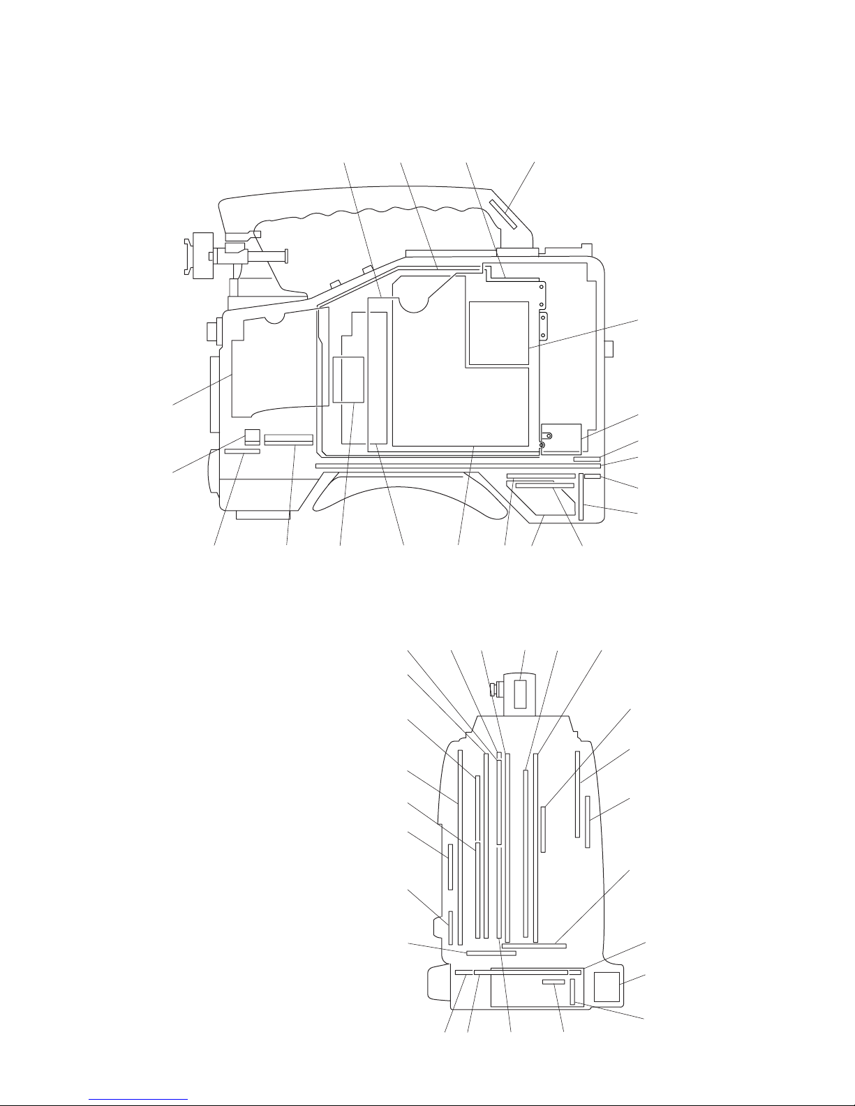
1-1. Locations of Main Parts and Circuit Configuration
1-1-1. Circuit Configuration and Locations of the Printed Wiring Boards
System Board Name Circuit No.
Configuration Function
CCD Block BI-199, 200, 201 CCD Imager #[
CN-2871 Connector for $\
DR-614
DR-614 CCD Driver $]
PA-340 Pre AMP #]
RP-131 Pulse Generator #=
TG-256 Timing #/
Generator
Camera AT-172 System ![
System Control
DCP-43 Camera Processor 2
Video Signal DVP-41 VTR Processor 3
System
Audio System AL-43 Audio AMP 0
APR-59AG Audio Volume !,
AXM-33 Connector 9
FP-152 Audio Processor 1
IFA-19G Lens Control #;
System/Servo MDC-13G Mecha Deck @/
Control Control
MDR-14G Drum Motor @-
Drive
SE-613 Sensor @.
SS-92G Servo/System !.
Control
RF System EQ-88G Equalizer @'
Power Supply CNB-23 Circuit Breaker 8
DC-111 Battery DC Filter 6
RE-186 Regulator $/
RE-187B Regulator #.
Connector IO-202 In/Out !Box
LP-114 Rear Tally 4
RM-201 Connector (RM) @]
Mic MA-103 Mic AMP #'
System Board Name Circuit No.
Configuration Function
Others BP-33 Battery !]
CCM-45G TELE-FILE @[
CI-32G 50pin adaptor $[
Interface
ENC-61 Rotary Encoder !'
HN-277G Harness #,
HP-103 Headphone !;
HP-104 Headphone 5
IF-794G Interface $-
KY-475G Function Key @,
MB-1096 Motherboard 7
PS-595 Power Supply @=
(Light)
RX-54G Wireless $=
Receiver
Interface
SW-1312 Light Switch #-
SW-1031 Switch #\
SW-1038 Switch !\
SW-1309 MIC SWITCH $;
TX-78 HDSDI Driver @;
Option DC-110A Down Converter !=
(HKDW-702)
MY-99 Picture Cache @\
(HKDW-703)
DC-139 2-3 Pull-Down/ !=
(HKDW-902R) Down Converter
PM-23 Slow Shutter/ $'
(HKDW-905R) Image Inverter
1-2
HDW-F900R/V1 (E)
<View of the inside panel assembly>
<Rear view>
1
23
4
5
6
7
$;
$'
9
0
!.
4
3
@;
2
$'
1
!]
@/
@-
@=
6
@]
9
!-
0
@\8
$;
5
7
!-
8
!=
![!]!\!;
!'
!,
@'
@[
!=
1-3
HDW-F900R/V1 (E)
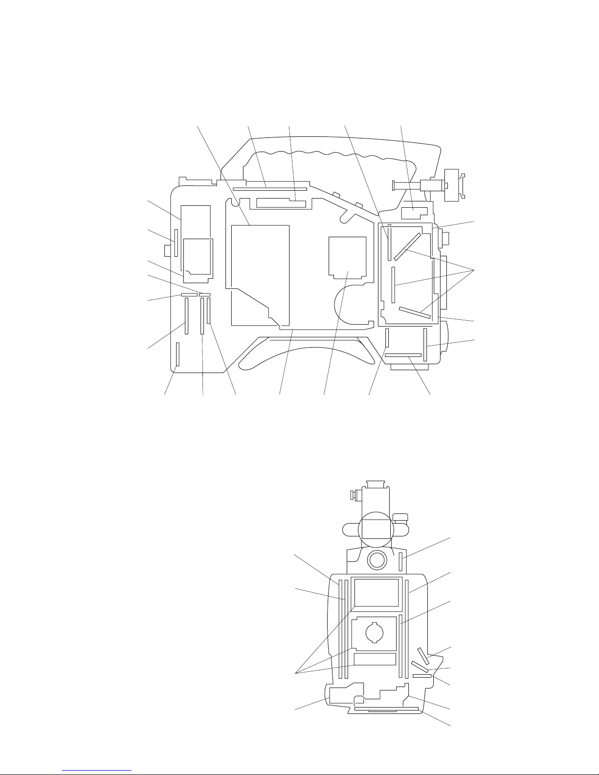
<View of the outside panel assembly>
<Front view>
#\
!\
$]
$\
!'
#-
#;
!;
#]
#=
#'
@-
@/
#,
#.
@]
$/
$-
$=
@[
$[
@=
!. @.
@,
#/ #-
#=
#[
#]
#\
#;
#[
#'
1-4
HDW-F900R/V1 (E)
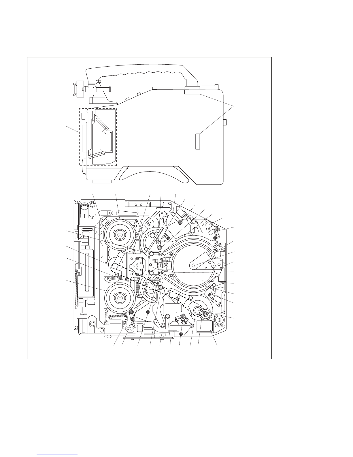
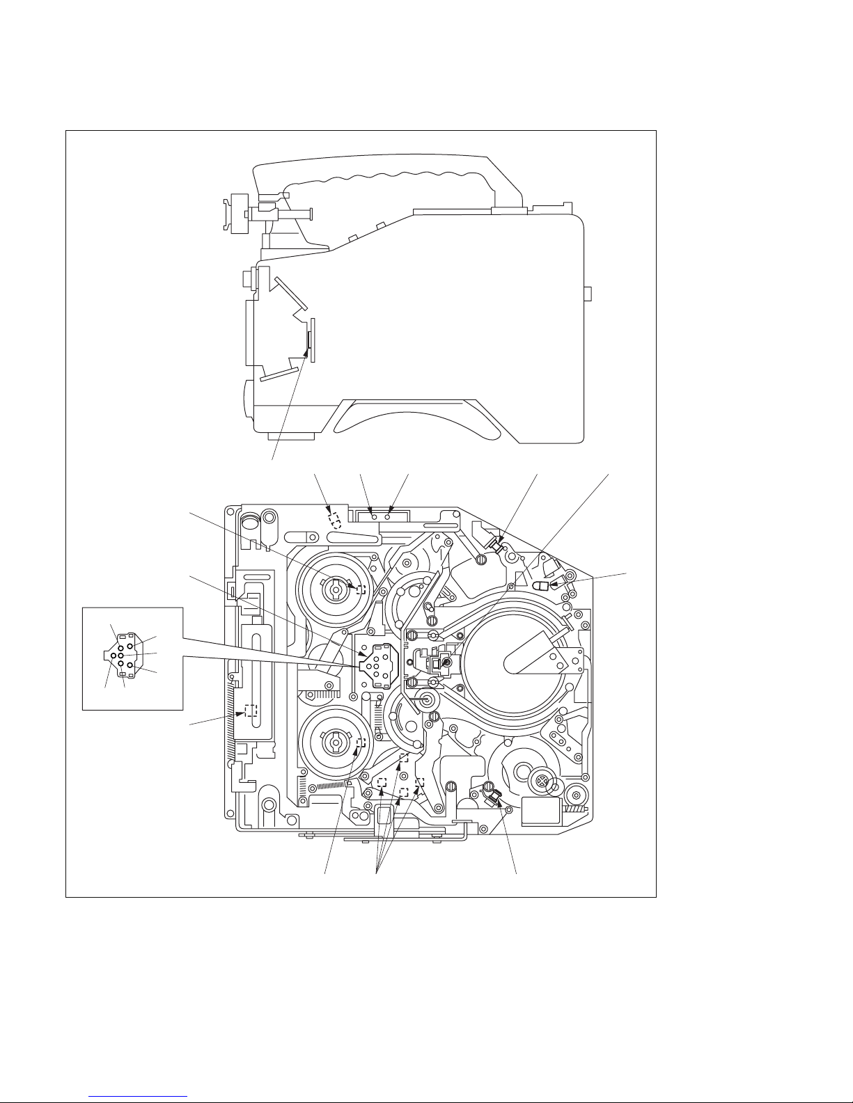
1-1-2. Locations of Main Mechanical Parts
1
2
3
4
5
6
#\
7
8
9
0
!-
!=
![
!]
!\
!;
!'
!,
!.
@/
@- @=#]
@[
@]
@\
@;
@'
@,
@.
#/
#-
#=
#[

1-5
HDW-F900R/V1 (E)
1 CCD block
2 Fan motor
3 Threading arm assembly
4 S1 tape guide (on top of S-slider assembly)
5 S2 tape guide (on top of S-slider assembly)
6 S4 tape guide (on top of threading arm assembly)
7 S5 tape guide (on top of S-tension regulator assembly)
8 S3 tape guide (on top of threading arm assembly)
9 Full erase head
0 CTL head
!- Brush assembly
!= Slip ring assembly
![ Cleaning assembly
!] Upper drum
!\ Lower drum
!; T4 guide
!' CUE/TC head
!, Manual eject gear (A)
!. Loading motor
@/ Capstan motor
@- T3 tape guide
@= T5 guide (on top of T-tension regulator assembly)
@[ Pinch roller assembly
@] T2 tape guide (on top of T slider assembly)
@\ T1 tape guide (on top of T slider assembly)
@; (T) soft brake
@' T reel table assembly
@, Timing belt
@. S-tension regulator band assembly
#/ S reel table assembly
#- T-tension regulator band assembly
#= (S) soft brake assembly
#[ Reel drive gear assembly
#] T-tension regulator assembly
#\ S-tension regulator assembly
1-6
HDW-F900R/V1 (E)
1-1-3. Functions and Locations of Sensors
1
2
3
4
5
6
6
7
8
9
0
!-
!=
ID1
ID2
ID3
ID4
ID5
ID6

1-7
HDW-F900R/V1 (E)
1 Temperature sensor
Detects temperature and drives the fan.
2 Cassette-in sensor
Detects whether a cassette is inserted or not.
3 REC INHIBIT sensor
Detects REC INHIBIT plug of a cassette tape.
4 Tape end sensor
Detects the tape end of a tape that is running in the FWD direction.
5 Full top sensor
Detects whether the inserted cassette tape is in the full top position or not.
6 Humid sensor
Detects the dew condensation inside the unit.
7 Tape top sensor
Detects the tape end of a tape that is running in the REV direction.
8 Function cam sensor
Detects the rotary position of the function cam.
9 T-reel table assembly rotation sensor
Detects rotation of the take-up reel table with the use of the T-reel table assembly rotation sensor. The
FG generator output of this sensor is input to the servo circuit where diameter of the remaining tape is
calculated.
0 Cassette lock sensor (switch)
Detects whether the cassette compartment assembly is locked or not.
!- Cassette ID sensor
ID1 : Tape type
Detects the tape type (Oxide or Metal).
ID2 : Tape thickness
Detects thickness of the tape that is wound in the cassette tape inserted in the set, with the
use of the tab on the rear of a cassette tape.
ID3 : Reel hub diameter
The reel hub diameter of a cassette tape is different depending on the length of a tape that
is wound in the cassette tape. The reel hub diameter sensor detects the reel hub diameter
with the use of a tab on the rear of a cassette tape.
ID4 to 6 : Tape format
Detects whether a cassette conforms to the HDCAM format or not.
!= S-reel table assembly rotation sensor
Detects rotation of the supply reel table with the use of the S-reel table assembly rotation sensor. The
output of this sensor is input to the servo circuit where diameter of the remaining tape is calculated.
1-8
HDW-F900R/V1 (E)
1-2. Matching Connectors
Use the following connectors at the ends of the cables
when connecting the cables during installation and maintenance, or alternately use the following cables.
Panel indication Matching connectors/cables
GENLOCK IN (RETURN)
TC IN 1-569-370-12
TC OUT Plug, BNC
TEST OUT
VBS/SDI OUT
*
HD SDI OUT 1-750-489-21 Plug, BNC or
BELDEN 8281 or equivalent
AUDIO IN CH1/CH2 1-508-084-00 XLR 3-pin, male
AUDIO OUT Audio cable
(XLR 5 pin-XLR 3-pin, 2 m)
CCXA-53 made by Sony or
equivalent
MIC IN +48 V 1-508-370-00 XLR 5-pin, male
DC IN 1-508-362-00 XLR 4-pin, female
DC OUT 12 V 1-566-425-11 round type 4-pin,
male
REMOTE 1-766-848-11 round type 8-pin,
male
EARPHONE Mini jack (commercially available
on market)
LIGHT Power tap (OE)
Made by ANTONBAUER Inc.,
33710 or equivalent
WIRELESS WRR-855A (by Sony) only
RECEIVER IN connectable
n
Do not connect with a connector/
cable other than above.
* : Camcorder in which DC-110A board (HKDW-702) and DC-139 board
(HKDW-902R) is installed.
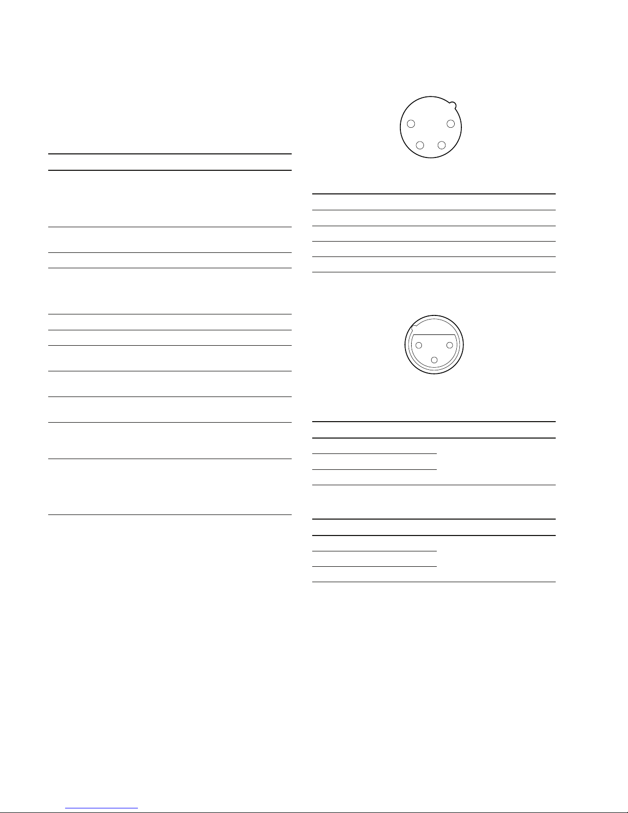
DC IN : XLR, 4-pin (Male)
__
__
_ EXT VIEW
__
__
_
No. Signal I/O Specifications
1 GND _ GND for BATT OUT (+)
2 _ No connection
3 _ No connection
4 BATT OUT (+)IN +11 to 17 V dc
AUDIO IN CH-1, CH-2 : XLR, 3-pin (Female)
__
__
_ EXT VIEW
__
__
_
(0 dBu = 0.775 V rms)
MIC/LINE INPUT
No. Signal I/O Specifications
1 MIC/LINE (G) __60 dBu/+4 dBu, selectable
2 MIC/LINE (X) IN
High impedance, Balanced
3 MIC/LINE (Y) IN
AES/EBU INPUT
No. Signal I/O Specifications
1 AES/EBU (G) _ 1Vp-p, 110Z, Balanced
2 AES/EBU (X) IN
3 AES/EBU (Y) IN
1-3. Signal Inputs and Outputs
Inputs
GENLOCK IN (RETURN) : 1.0 V p-p, 75 Z
TC IN : 0.5 V to 18 V p-p, 10 kZ
Outputs
TEST OUT : 1.0 V p-p, 75 Z unbalanced
VBS/SDI OUT
*1, 2
: VBS 1.0 V p-p, 75 Z unbalanced,
or SDI 0.8 V p-p, 75 Z, 270 Mbps
TC OUT : 1.0 V p-p, 75 Z
HD SDI OUT : 0.8 V p-p, 75 Z, 1.485 Gbps
EARPHONE : 8 Z or more, _∞ to _18 dBu variable
*1 : Camcorder in which DC-110A board (HKDW-702) and DC-139 board
(HKDW-902R) is installed.
*2 : Selectable by the SD REAR BNC OUT in the OUTPUT SEL page of the
menu.
1
23
4
1
2
3
1-9
HDW-F900R/V1 (E)
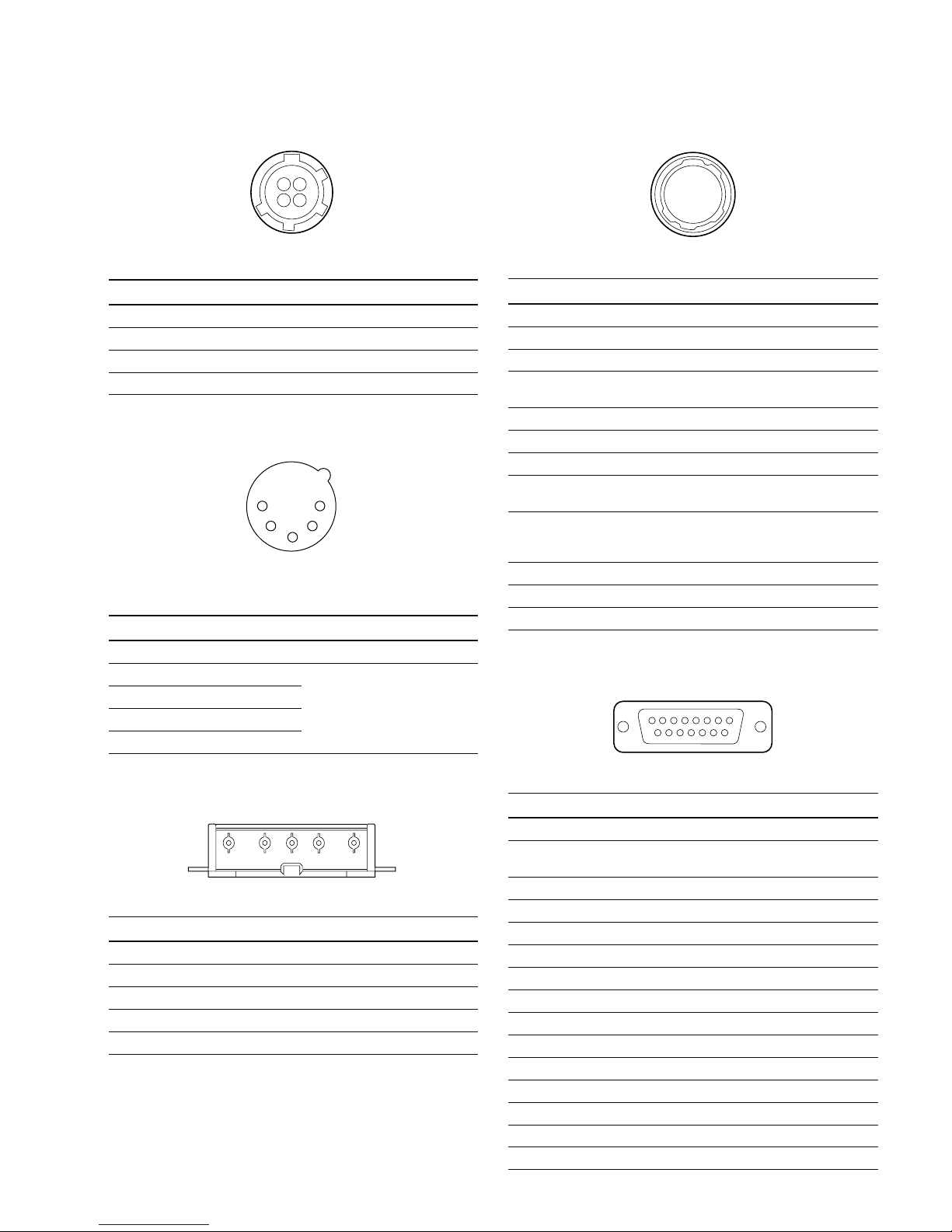
DC OUT 12 V : DIN, 4-pin (Female)
__
__
_ EXT VIEW
__
__
_
No. Signal I/O Specifications
1 UNREG GND _ GND for POWER
2 _ No connection
3 _ No connection
4 UNREG +12 V OUT +11 to 17 V dc
AUDIO OUT : XLR, 5-pin (Male)
__
__
_ EXT VIEW
__
__
_
(0 dBu = 0.775 V rms)
No. Signal I/O Specifications
1 ANALOG GND _
2 AUDIO CH-1 (X) OUT 0 dBm (600 Z terminated)
3 AUDIO CH-1 (Y) OUT
4 AUDIO CH-2 (X) OUT
5 AUDIO CH-2 (Y) OUT
BATT IN : 5-pin (Male)
__
__
_ EXT VIEW
__
__
_
No. Signal I/O Specifications
1 BATT (_)IN
2 BATT ID IN
3 BATT REM IN
4 LIGHT CONT OUT
5 BATT (+) IN+11 to 17 V dc
LENS : 12-pin (Female)
__
__
_ EXT VIEW
__
__
_
No. Signal I/O Specifications
1 RET (SW) IN ON : 0 V, OFF : OPEN
2 VTR TRIG IN ON : 0 V, OFF : OPEN
3 LENS GND _
4 AUTO +5 V IN AUTO : +5 V,
MANU : 0 V or OPEN
5 IRIS CONT OUT +3.4 V (F16) to +6.2 V (F2.8)
6 UNREG +12 V OUT +11 V to 17 V
7 IRIS PSTN IN +3.4 V (F16) to +6.2 V (F2.8)
8 REMOTE/LOCAL OUT AUTO IRIS : 0 V
MANUAL IRIS : +5 V
9 EXTENDER IN EX 2 ON : 0 V
EX 0.8 ON : +1.8 V
OFF : +4.8 V
10 ZOOM PSTN IN WIDE : 2 V, TELE : 7 V
11 LENS RX
12 LENS TX
WIRELESS RECEIVER IN : D-sub, 15-pin (Female)
__
__
_ EXT VIEW
__
__
_
No. Signal I/O Specifications
1 GND _ GND for AUDIO IN
2 AUDIO IN IN WIRELESS RECEIVER
AUDIO IN
3 _
4 DC +7V OUT OUT
5 GND _
6 _
7 _
8 GND _
9 WRR CLK IN WRR SERIAL CLOCK
10 CS OUT WRR SELECT
11 WRR DI OUT WRR SERIAL IN
12 WRR DO IN WRR SERIAL OUT
13 _
14 EXT OSC OUT _
15 OSC GND _
14
32
1
2
3
4
5
12345
1
2
3
4
5
6
7
8
9
0
!-!=
1
8
9
15
1-10
HDW-F900R/V1 (E)
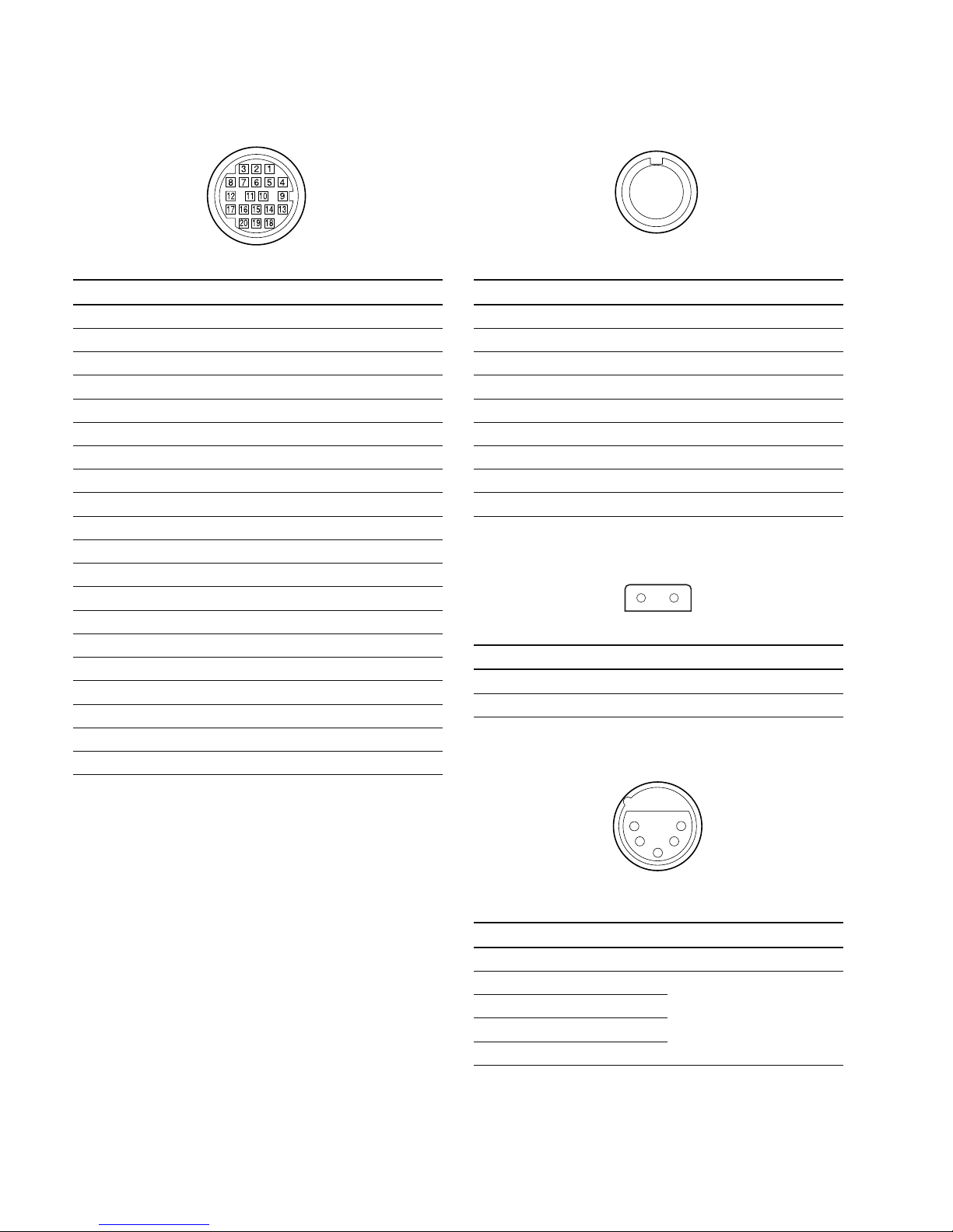
VF : 20-pin (Female)
__
__
_ EXT VIEW
__
__
_
No. Signal I/O Specifications
1 SDA VF I/O TTL level
2 _ No connection
3 _ No connection
4 SCL VF OUT TTL level
5 COLOR/BW IN ON : Color, OFF : B/W
6 _ No connection
7 _ No connection
8 G TALLY OUT ON : 5 V, OFF : GND
9 VF PEAKING CTL OUT 1.0 V p-p, Zo = 75 Z
10 _ No connection
11 _ No connection
12 VF VIDEO (Y) OUT 1.0 V p-p, Zo = 75 Z
13 VF VIDEO GND _ GND for VIDEO
14 VF VIDEO (Pb) OUT ± 0.35 V p-p, Zo = 75 Z
15 VF VIDEO (Pr) OUT ± 0.35 V p-p, Zo = 75 Z
16 _ No connection
17 R TALLY (UP) OUT ON : 5 V, OFF : GND
18 _ No connection
19 VF GND _ GND for VF
20 UNREG +12 V OUT +11 V to 17 V
REMOTE : 8-pin (Female)
__
__
_ EXT VIEW
__
__
_
No. Signal I/O Specifications
1 TX RCP DATA (X) OUT SERIAL DATA OUT
2 TX RCP DATA (Y) OUT SERIAL DATA OUT
3 RX RCP DATA (X) IN SERIAL DATA IN
4 RX RCP DATA (Y) IN SERIAL DATA IN
5 TX GND _ GND for TX
6 UNREG +12 V OUT +11 V to 17 V
7 UNREG (GND) _ GND for UNREG
8 Y OUT 1.0 V p-p, Zo = 75 Z
CHASSIS GND _ CHASSIS GND
LIGHT : 2-pin (Female)
__
__
_ EXT VIEW
__
__
_
No. Signal Specifications
1 LIGHT +12 V OUT 50 W MAX
2 GND
MIC IN
++
++
+48 V : XLR, 5-pin (Female)
__
__
_ EXT VIEW
__
__
_
(0 dBu = 0.775 V rms)
No. Signal I/O Specifications
1 CAM MIC (G) __50 dBu
2 CAM MIC1 (X) IN High impedance, Balanced
3 CAM MIC1 (Y) IN
4 CAM MIC2 (X) IN
5 CAM MIC2 (Y) IN
1
8
27
36
45
12
1
5
4
2
3
1-11
HDW-F900R/V1 (E)
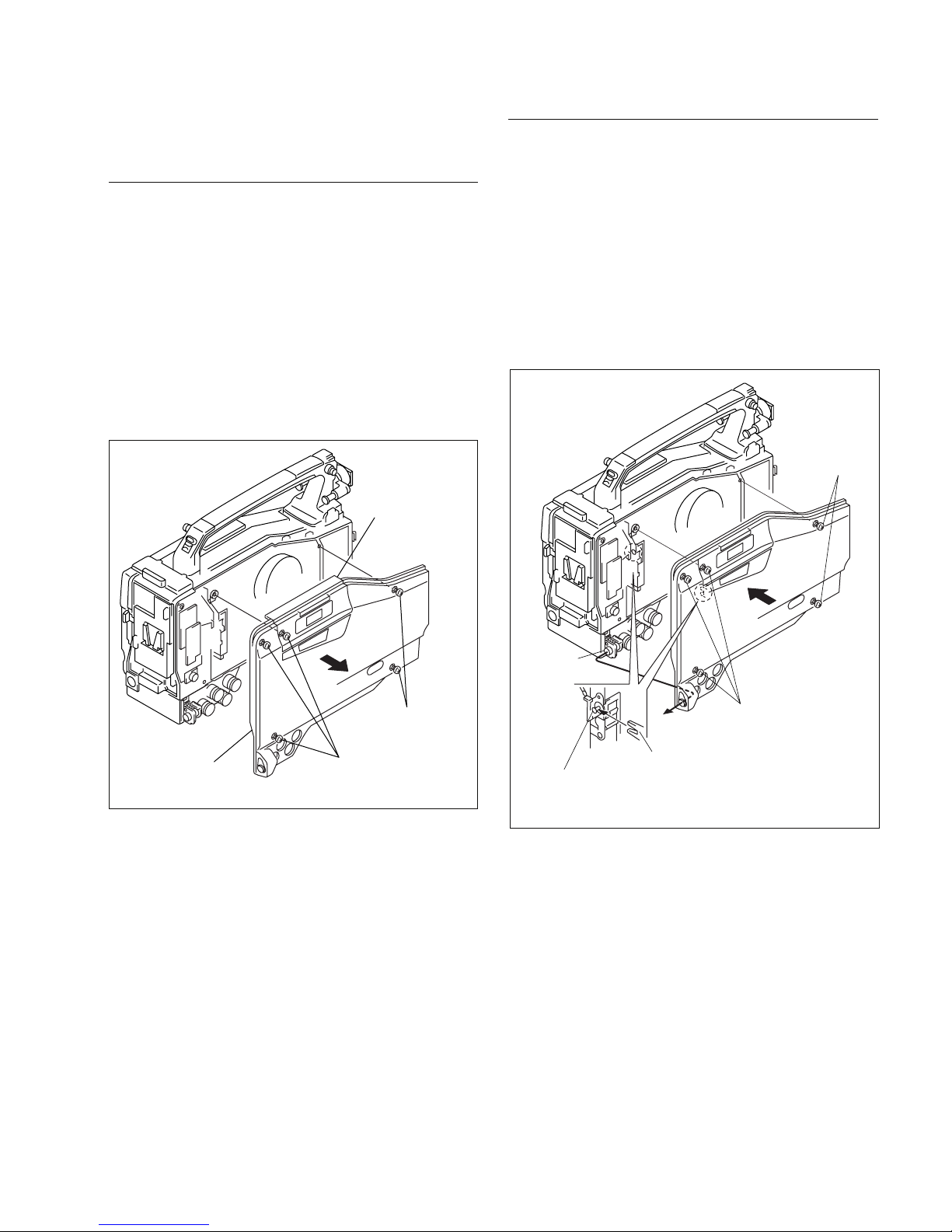
1-4. Removing and Reinstalling the
Outside Panel Assembly
Removal
n
Be sure to set the POWER switch to OFF, unplug the
power cord or remove the battery before starting any of the
following procedure to protect inside of the unit from
damage.
1. Loosen a screw (with drop-safe) in the left of the front
lid assembly.
2. Loosen the four screws (with drop-safe) and remove
the outside panel assembly.
Reinstallation
1. Pass the connector of the RM board of the main unit
through the hole of the outside panel assembly.
While inserting the hook of the outside panel assembly
into the guide shaft of the cassette compartment
assembly, install the outside panel assembly.
2. Reinstall it by reversing the steps of disassembling.
n
Standard tightening torque :
Screw (with drop-safe, B3 x 12)
80 x 10-2 N.m (8 kgf.cm)
Outside panel
assembly
Screws
(with drop-safe)
Screws
(with drop-safe)
Front lid assembly
Screws
(with drop-safe)
RM board
connector
Screws
(with drop-safe)
Hook of outside panel assembly
Guide shaft of
cassette compartment
assembly
1-12
HDW-F900R/V1 (E)
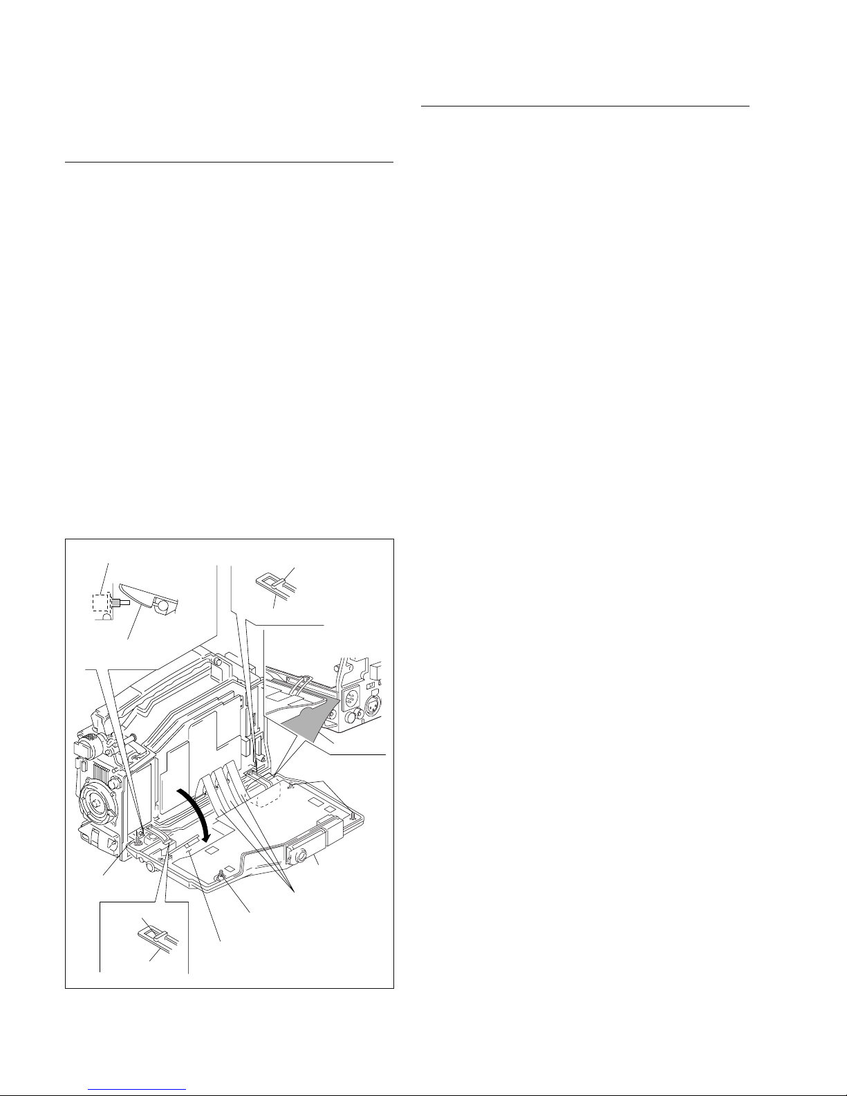
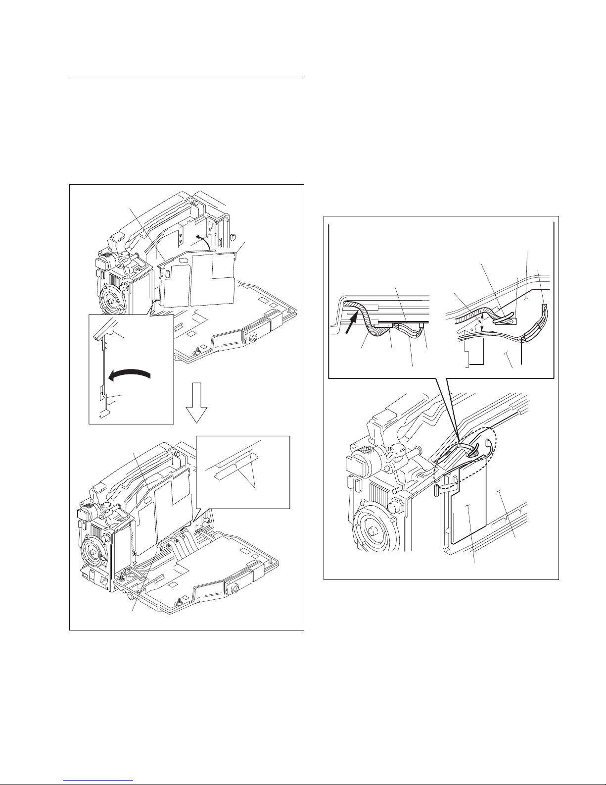
1-5. Opening and Closing the Inside
Panel Assembly
Opening
m
. Be sure to set the POWER switch to OFF, unplug the
power cord or remove the battery before starting any of
the following procedure to protect inside of the unit from
damage.
. Insert a piece of paper between the hinge and the
connector box.
1. Loosen the four screws (with drop-safe) and open the
inside panel assembly in the direction of the arrow.
m
. The flexible card wires that is connected to the FP-
152 board, will be significantly shortened its life if it
is folded. Be very careful not to fold the flexible
card wires.
. Stand the unit in the posture that the POWER switch
side faces upward when the inside panel assembly is
opened.
Closing
1. Check that the hinges in the right and left are engaged
securely with the hooks of the chassis.
2. Insert the inside panel assembly and tighten the four
screws (with drop-safe).
n
Standard tightening torque :
Screw (with drop-safe, B3 x 12)
80 x 10_2 N.m (8 kgf.cm)
n
Be careful not to pinch the harness between the inside
panel assembly and the chassis.
Flexible card wires
Inside panel
assembly
Screw
(with drop-safe)
FP-152 board
Inside panel
assembly
Hook
Hinge
POWER switch
Hinge
Hook
Screws
(with drop-safe)
Screw
(with drop-safe)
Place a sheet of paper
here to protect
the frame.
Paper
1-13
HDW-F900R/V1 (E)
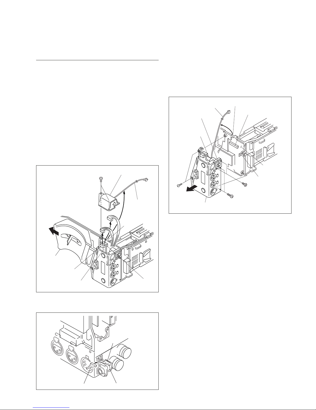
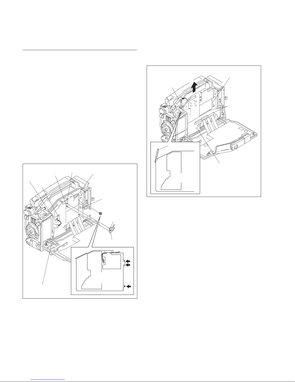
1-6. Removing and Reinstalling the
Connector Box
Removal
1. Remove the outside panel assembly.
(Refer to Section 1-4.)
2. Remove the inside panel assembly.
(Refer to Section 1-5.)
3. Remove the DCP board assembly and the DVP board
assembly. (Refer to Sections 1-7-1 and 1-7-2.)
4. Slide the shoulder pad assembly in the direction of the
arrow.
5. Remove the two screws (P2 x 4). While removing the
VIDEO OUT assembly, remove the coaxial cable from
the groove.
6. Disconnect the harness from connectors (CN101 and
CN103) on CNB-23 board.
7. Disconnect the harness from the connector (CN114)
on the RM-201 board.
8. Remove the two precision screws (P2.6 x 5) fixing
the DC IN connector and separate it from the shield
finger (BATT).
9. Remove the four screws (B3 x 8). Loosen the board-
to-board connector that is connected to the MB-1096
board. While removing the connector box assembly in
the direction of the arrow, remove the coaxial cable
and harness from the groove.
10. Reinstall it by reversing the steps of disassembling.
m
. When attaching the VIDEO OUT assembly, route
the coaxial cable such that the coaxial cable passes
through the groove.
. If the coaxial cable is pinched between the frame
and the VIDEO OUT assembly or the CNBOX sub
panel, the coaxial cable can have open-circuit.
n
Standard tightening torque :
P2 x 4 : 19 x 10_2 N.m (1.9 kgf.cm)
B3 x 8 : 80 x 10_2 N.m (8 kgf.cm)
CNB-23 board
CN103
CN101
Coaxial cable
(Orange)
Groove
Shoulder pad
assembly
P2 x 4
VIDEO OUT assembly
Coaxial cable (Brown)
B3 x 8
B3 x 8
Precision screws
P2.6 x 5
MB-1096
board
Connector box assembly
Groove
DC IN connector
Board-to-board
connector
Board-to-board
connector
Shield finger
(BATT)
RM-201 board
CN114
Harness
1-14
HDW-F900R/V1 (E)
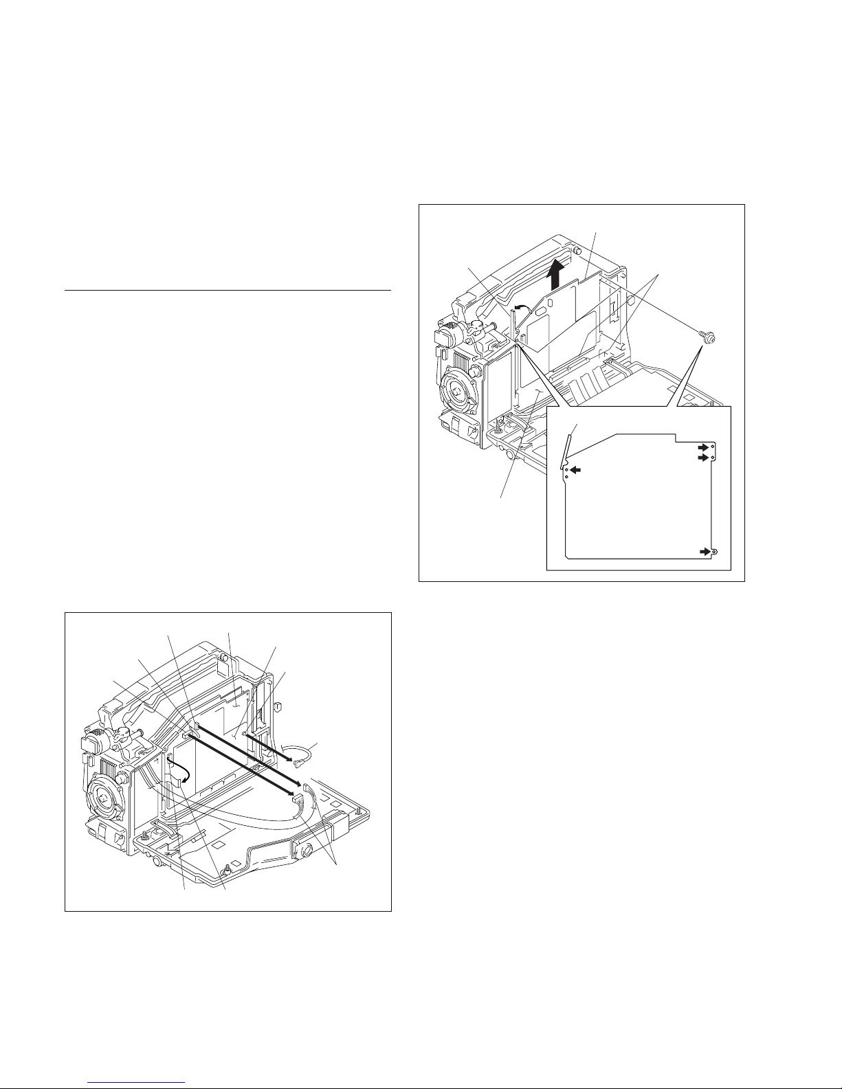
1-7. Removing and Reinstalling the
Plug-in Boards
When removing and reinstalling the plug-in boards, be
very careful not to damage the parts on the printed board
and also not to install them in the wrong direction or in the
wrong slot.
1-7-1. DCP Board Assembly
Removal
1. Open the inside panel assembly.
(Refer to Section 1-5.)
2. Remove the harness from the coating lead pin, then
disconnect the harnesses from the connectors (CN3
and CN4) of the DCP-43 board.
3. Disconnect the flexible card wire from the connector
(CN105) of the DCP-43 board.
n
. Life of flexible card wire will be significantly
shortened if it is folded. Be very careful not to fold
the flexible card wire.
4. Remove the coaxial cable from the connector (CN1/
DC-110A, CN601/DC-139) when the DC-110A/139
board is installed.
5. Remove the four screws. Open the board levers in the
direction of arrow A to release the board-to-board
connector that is connected to the MB-1096 board.
Pull the DCP board assembly in the direction of arrow
B to disconnect, and remove the DCP board assembly.
DCP-43 board
DC-110A/
DC-139 board
CN3
CN4
CN105
CN1/DC-110A
board,
CN601/DC-139
board
Flexible card wire
Coaxial cable
(Orange)
Coating lead pin
Harnesses
DCP board assembly
MB-1096 board
DCP-43 board
Board lever
Board lever
A
B
Board-to-board
connectors
PSW2 x 5
1-15
HDW-F900R/V1 (E)
Reinstallation
1. Close the board levers.
2. Insert the DCP board assembly into the groove on the
board holder in the direction of arrow A, and raise the
DCP board assembly in the direction of arrow B.
3. Connect the DCP board assembly and the MB-1096
board with the board-to-board connector.
4. Reinstall it by reversing the steps of disassembling.
m
. When re-installing the harness that is disconnected
in step 2, the CN3 harness must be hooked on the
top edge of the AT-172 board.
. When re-installing the CN4 harness, twist it by 3
turns and install it by pushing in the direction of
arrow A. The CN4 harness must be installed 20 mm
more far from the CN3 harness.
. Fix the harness with the coating lead pin.
Illustration when viewed
from the top
Illustration when viewed
from the front
Distance of
20 mm
or more
DCP-43 board
DCP-43 board
AT-172 board
AT-172 board
DCP-43 board
CN4
A
CN3
CN4
CN3
Harness
Harness
Coating
lead pin
DCP board
assembly
DCP board
assembly
B
A
A
Board holder
(F)
Board lever
Board lever
Board-to-board
connectors
MB-1096 board
1-16
HDW-F900R/V1 (E)
6. Open the board levers in the direction of arrow A and
remove the board-to-board connector that is connected
to the MB-1096 board, and remove the DVP board
assembly in the direction of arrow B.
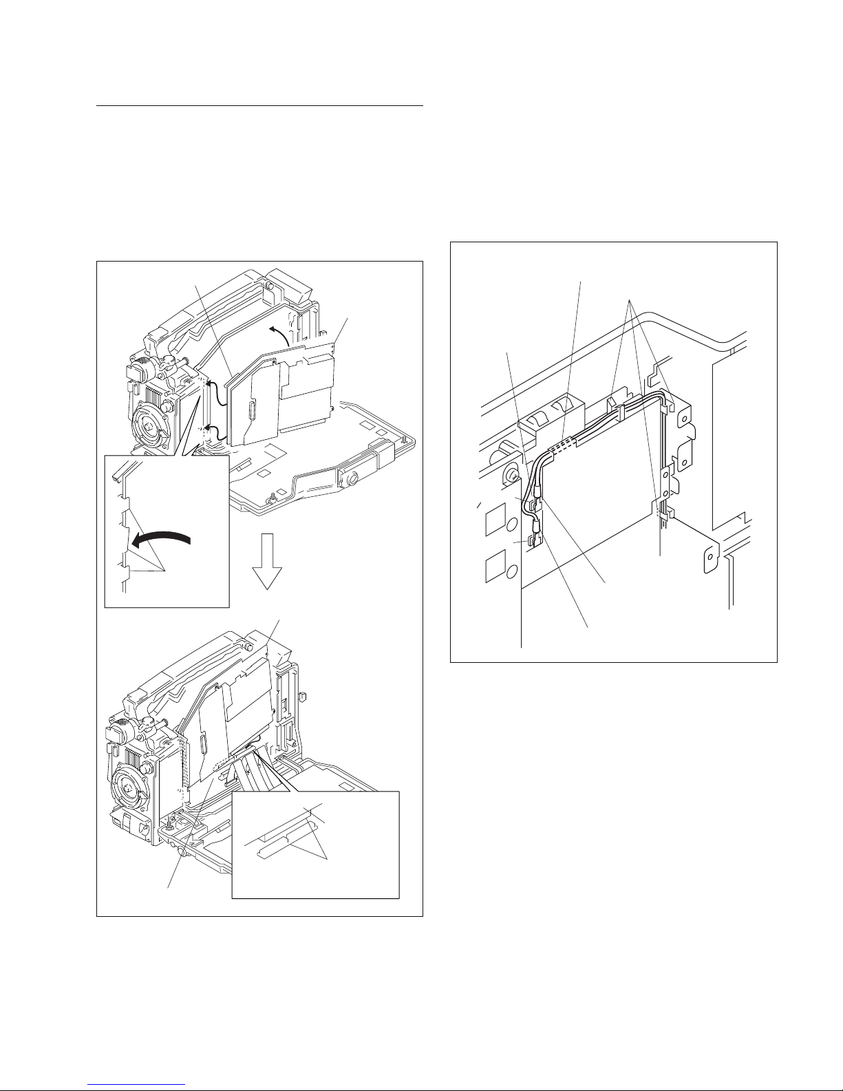
1-7-2. DVP Board Assembly
Removal
1. Open the inside panel assembly.
(Refer to Section 1-5.)
2. Remove the DCP board assembly.
(Refer to Section 1-7-1.)
3. Remove the flexible card wire from the EQ-88G board
connector (CN101).
n
Life of flexible card wire will be significantly
shortened if it is folded. Be very careful not to fold
the flexible card wire.
4. Remove the two coaxial cables from the connector
(CN201, CN202) on the TX-78 board.
5. Remove the three screws (PSW 2 x 5) that fix the
DVP board assembly.
EQ-88G board
TX-78 board
DVP board
assembly
CN202
CN201
Coaxial cable (Green)
Coaxial cable
(Brown)
CN101
Flexible card wire
PSW2 x 5
DVP board
assembly
DVP board
assembly
MB-1096 board
A
B
DVP board
assembly
Board lever
Board lever
Board-to-board
connectors
1-17
HDW-F900R/V1 (E)
Reinstallation
1. Close the board levers.
2. Insert the DVP board assembly into the groove on the
board holder in the direction of arrow A, and raise the
DVP board assembly in the direction of arrow B.
3. Connect the DVP board assembly and the MB-1096
board with the board-to-board connector.
4. Reinstall it by reversing the steps of disassembling.
n
When routing the two coaxial cables, pass them
through the three clamps and the groove on the SDI
shield plate, and connect the coaxial cable (green) to
CN201 on the TX-78 board, and the coaxial cable
(brown) to CN202.
DVP board
assembly
DVP board assembly
DVP board
assembly
Board
holder (F)
MB-1096 board
B
A
A
A
Board lever
Board-to-board
connectors
Coaxial cable (Brown)
Coaxial cable (Green)
Groove on the SDI shield plate Insert
a sheet of paper in the protected part.
TX-78 board
Clamps
CN201
CN202
1-18
HDW-F900R/V1 (E)
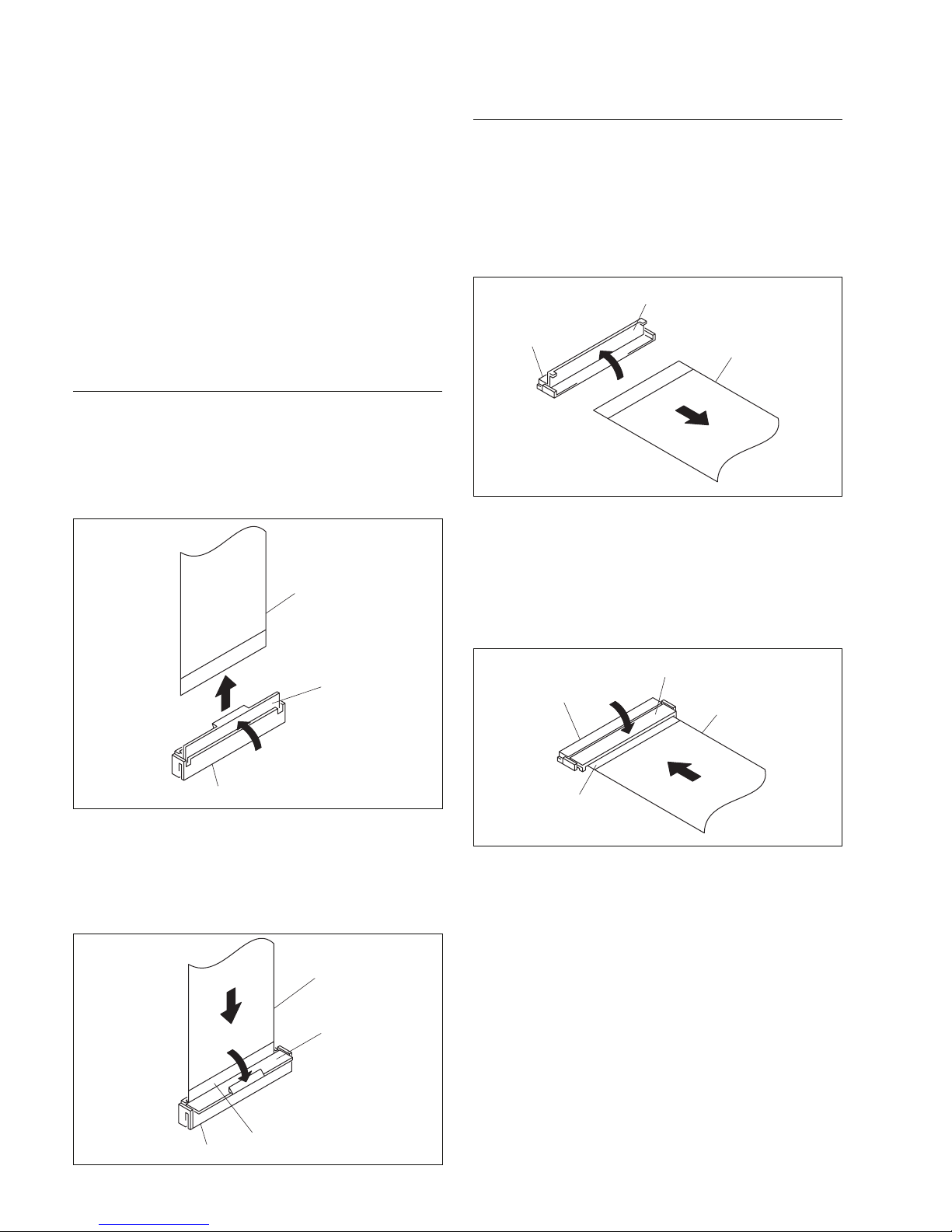
1-8. Removing and Reinstalling the
Flexible Card Wires
This unit uses two types of flexible card wire.
m
. Life of flexible card wire will be significantly shortened if it
is folded. Be very careful not to fold the flexible card wire.
.
When a flexible card wire is disconnected, check if it has
peeling-off or scratch on the tin plated contact of the
connector. If the copper plating of the base material
exposes due to wear of the tin plated contact of the
connector, replace it with the new flexible card wire.
Type-A
Removal
1. Open the connector latch in the direction of arrow A to
release the lock.
2.
Remove the flexible card wire in the direction of arrow B.
Reinstallation
1. Hold the flexible card wire with its blue surface to the
front, and insert it in the direction of arrow A.
2. Close the connector latch in the direction of arrow B to
lock it.
Type-B
Removal
1. Open the connector latch in the direction of arrow A to
release the lock.
2
Remove the flexible card wire in the direction of arrow B.
Reinstallation
1. Hold the flexible card wire with its blue surface to the
front, and insert it in the direction of arrow A.
2. Close the connector latch in the direction of arrow B to
lock it.
Flexible card wire
Connector
Connector latch
A
B
Flexible card wire
Connector
Connector latch
A
B
Blue surface
Flexible card wire
Connector
Connector latch
A
B
Flexible card wire
Connector
Connector latch
A
B
Blue surface
1-19
HDW-F900R/V1 (E)
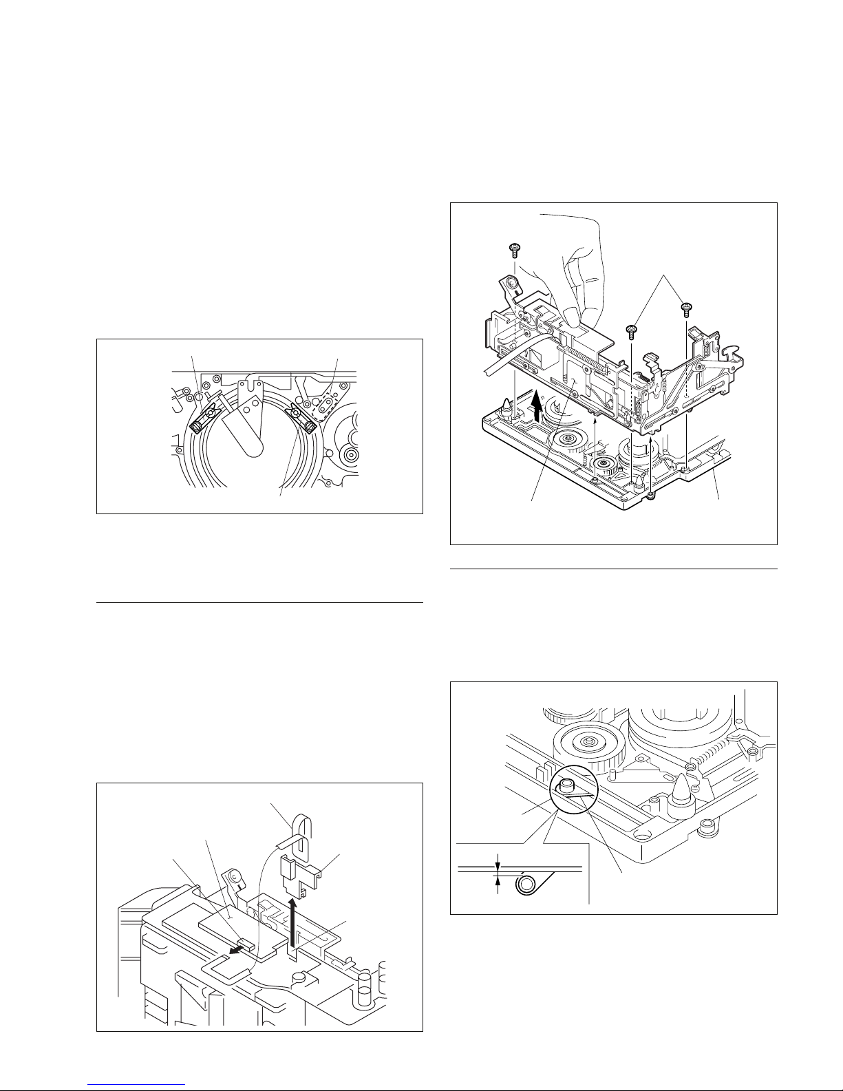
4. Remove the three precision screws (P1.4 x 3.5) and
move the cassette compartment assembly by holding
the specified position as shown in the illustration and
remove the cassette compartment assembly in the
direction of the arrow.
Reinstallation
1. Adjust position of the joint arm so that the gap between the outside circumference of the white roller of
the joint arm and the end surface of the mechanical
deck assembly is 0.5 mm.
1-9. Removing and Reinstalling the
Cassette Compartment
m
. Be sure to set the POWER switch to OFF, unplug the
power cord or remove the battery before starting any of
the following procedure to protect inside of the unit from
damage.
. Only when the release plate is attached to the T-tension
regulator assembly, remove and reinstall the Cassette
compartment assembly at the thread position shown in
the illustration below. When the TC head is at the other
position, T-tension regulator assembly interferes with the
cassette compartment.
n
. Cassette compartment can be removed when it is raised
up or when it pushed down.
Removal
1. Remove the outside panel assembly.
(Refer to Section 1-4.)
2. Remove the FL-283 printed wiring board from the
connector (CN1) on the CCM-45G board.
3. Remove the FL-283 printed wiring board while
removing the cable retainer 2 from the notch.
n
Life of the FL-283 printed wiring board will be
significantly shortened if it is folded. Be very careful
not to fold the FL-283 printed wiring board.
T slider (at the front of the TC head)
S slider
TC head
CCM-45G board
CN1
FL-283 printed wiring board
Notch
Cable retainer 2
Cassette compartment
assembly
Mechanical deck
assembly
Precision screw
P1.4 x 3.5
Precision screws
P1.4 x 3.5
0.5 mm
Roller (WHT)
Joint arm
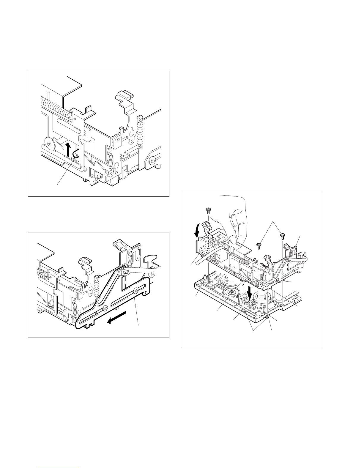
1-20
HDW-F900R/V1 (E)
2. Raise the white locking roller of the cassette compartment assembly to set the cassette compartment
assembly to its up position.
3. Slide the cam plate (A) of the right side of the cassette
compartment assembly in the direction of the arrow as
far as it can go.
4. Hold the cassette compartment assembly at the position
shown in the illustration and insert the chassis so that
the two cassette guide pins enter into the round hole of
the stage.
At this moment, confirm that the white roller at the
other end of the joint arm that is adjusted of its position
at step 1, enters into the notch of the cam plate (A) on
the right side.
5. Press the lid arm (L) of the cassette compartment
assembly and check to see that the stage can move up
and down smoothly. If the stage does not move up and
down smoothly, check above procedure starting from
step 1.
6. Attach the cassette compartment assembly with three
screws.
n
Standard tightening torque :
10 x 10_2 N.m (1.0 kgf.cm)
Locking roller (WHT)
Cam plate (A)
Notch of
cam plate (A)
Precision screw
P1.4 x 3.5
Precision screws
P1.4 x 3.5
Lever
Stage
Roller (WHT)
at the other end
Roller (WHT) of
step 1
Joint arms
Notch
Cassette
guide pin
Cassette guide pin
Round hole
of stage
Round hole
of stage
 Loading...