

Snorkel sn17573-19999 User Manual [en, de, fr]

Operator Manual
Guide De L’opérateur
Betriebsanleitung
XSeries
SERIAL NO. 17573 to Current
WARNING
All personnel shall carefully read, understand and follow all safety rules,
operating instructions, and National Safety Instructions/Requirements
before operating or performing maintenance on any UpRight Aerial Work
Platform.
The first section of this Operator Manual is the English language version.
AVERTISSEMENT
Tout le personnel doit lire attentivement, bien comprendre et suivre toutes
lesrèglesdesécurité,lemoded’emploietlesrèglesnationalesdesécurité avant d’entretenir ou d’utiliser une plate-forme élévatrice UpRight.
La deuxième section du guide de l’opérateur est la version française.
WARNUNG
Alle Bediener müssen die Sicherheitsregeln, Betriebsanleitungen sowie
geltenden Sicherheitsanweisungen/-anforderungen gründlich durchlesen,
verstehen und befolgen, bevor sie an irgendeiner UpRight-Hocharbeitsbühne Wartungsarbeiten ausführen oder diese in Betrieb nehmen.
Der dritte Abschnitt dieser Betriebsanleitung ist deutschsprachig.
P/N 060572-027
X Series
Serial Numbers 17573 – Current
E
NGLISH
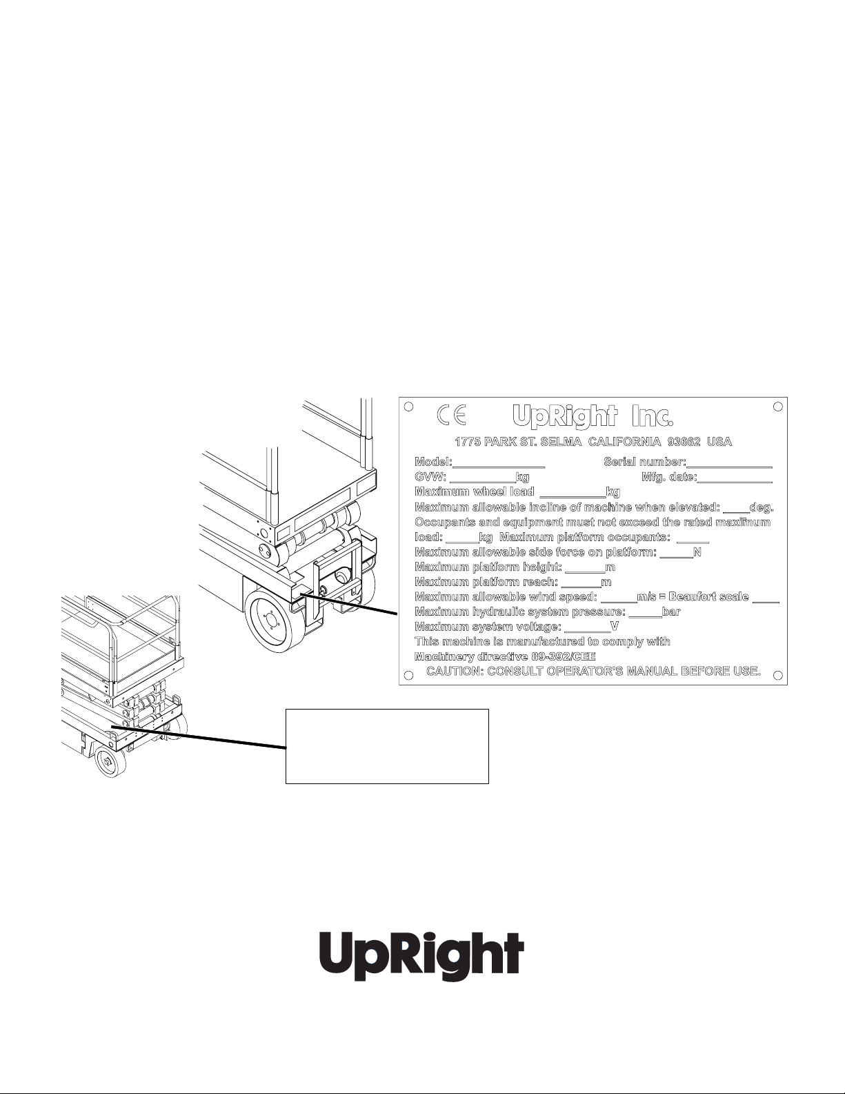
When contacting UpRight for service or parts information, be sure to include the MODEL and SERIAL NUMBERS from the
equipment nameplate. Should the nameplate be missing, the SERIAL NUMBER is also stamped on top of the chassis
above the front axle pivot.
F
RANÇAIS
Lors des communications avec UpRight pour des informations au sujet de l’entretient ou des pièces, ne pas oublier
d’inclure les NUMÉROS DE MODÈLE et de SÉRIE inscrits sur la plaque signalétique. Si la plaque signalétique manque, le
NUMÉRO DE SÉRIE est également estampé sur le dessus du châssis, au-dessus de l’axe pivot avant.
D
EUTSCH
Stellen Sie sicher, dass Sie die MODELL- und SERIENNUMMERN auf dem Gerätetypenschild angeben, wenn Sie sich mit
UpRight bezüglich Wartungs- oder Ersatzteilinformationen in Verbindung setzten. Sollte das Typenschild fehlen, finden Sie
die SERIENNUMMER auch auf dem Fahrwerk über der vorderen Schwenkachse.
UpRight, Inc.
1775 Park Street
Selma, California 93662
TEL: 559/891-5200
FAX: 559/891-9012
PARTS: 1-888-UR-PARTS
PARTS FAX: 559/896-9244
Stamped Serial Number
Estampille de numéro de série
Eingestanzte Seriennummer
Call Toll Free in U.S.A.
1-800-926-LIFT
UpRight International
Support Centre
61-63 Hong Kong Straat
3047 BR Rotterdam
Netherlands
TEL: +31-10-238-0000
FAX: +31-10-238-0001
Parts Tel: +31-10-490-8090
Parts Fax: +31-10-490-8099
OPERATION MANUAL
C
C
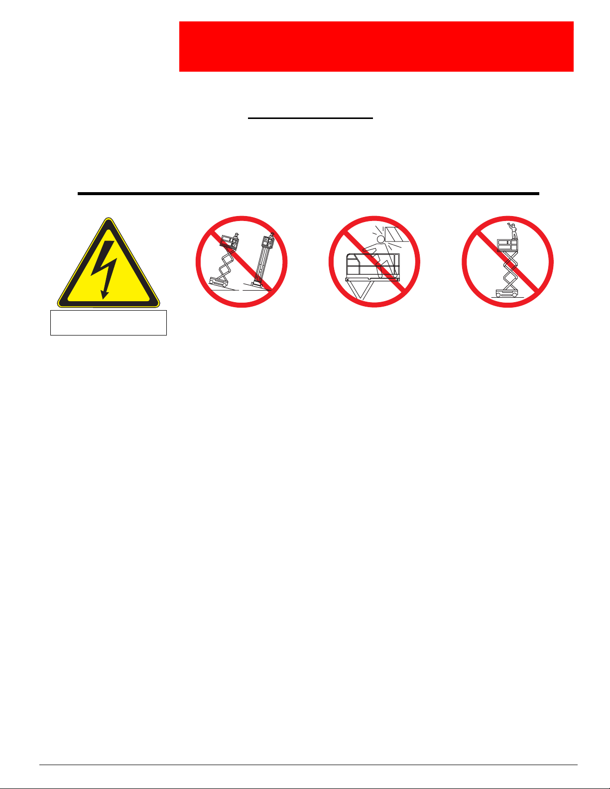
WARNING
All personnel shall carefully read, understand and follow all safety rules and operating
instructions before operating or performing maintenance on any UpRight aerial work platform.
Safety Rules
Safety Rules
Safety RulesSafety Rules
Electrocution Hazard
Electrocution Hazard TipOver Hazard
Electrocution HazardElectrocution Hazard
TipOver Hazard
Tip Over HazardTip Over Hazard
ollision Hazard
ollision Hazard Fall Hazard
Collision HazardCollision Hazard
Fall Hazard
Fall HazardFall Hazard
THIS MACHINE IS NOT
INSULATED!
USE OF THE AERIAL WORK PLATFORM: This aerial work platform is intended to lift persons and his tools as well as the material
used for the job. It is designed for repair and assembly jobs and assignments at overhead workplaces (ceilings, cranes, roof structures,
buildings etc.). All other uses of the aerial work platform are prohibited!
THIS AERIAL WORK PLATFORM IS NOT INSULATED! For this reason it is imperative to keep a safe distance from live parts of electrical equipment!
Exceeding the specified permissible maximum load is prohibited! See “Special Limitations” on page 4 for details.
The use and operation of the aerial work platform as a lifting tool or a crane (lifting of loads from below upwards or from up high on
down) is prohibited!
NEVER exceed the manual force allowed for this machine. See “Special Limitations” on page 4 for details.
DISTRIBUTE all platform loads evenly on the platform.
NEVER operate the machine without first surveying the work area for surface hazards such as holes, drop-offs, bumps, curbs, or debris;
and avoiding them.
OPERATE machine only on surfaces capable of supporting wheel loads.
NEVER operate the machine when wind speeds exceed this machine’s wind rating. See “Beaufort Scale” on page 4 for details.
IN CASE OF EMERGENCY push EMERGENCY STOP switch to deactivate all powered functions.
IF ALARM SOUNDS while platform is elevated, STOP, carefully lower platform. Move machine to a firm, level surface.
Climbing up the railing of the platform, standing on or stepping from the platform onto buildings, steel or prefab concrete structures, etc.,
is prohibited!
Dismantling the swing gate or other railing components is prohibited! Always make certain that the swing gate is closed and securely
locked!
It is prohibited to keep the swing gate in an open position (held open with tie-straps) when the platform is raised!
To extend the height or the range by placing of ladders, scaffolds or similar devices on the platform is prohibited!
NEVER perform service on machine while platform is elevated without blocking elevating assembly.
INSPECT the machine thoroughly for cracked welds, loose or missing hardware, hydraulic leaks, loose wire connections, and damaged
cables or hoses before using.
VERIFY that all labels are in place and legible before using.
NEVER use a machine that is damaged, not functioning properly, or has damaged or missing labels.
To bypass any safety equipment is prohibited and presents a danger for the persons on the aerial work platform and in its working
range.
NEVER charge batteries near sparks or open flame. Charging batteries emit explosive hydrogen gas.
Modifications to the aerial work platform are prohibited or permissible only at the approval by UpRight.
AFTER USE, secure the work platform from unauthorized use by turning both keyswitches off and removing key.
NEVER elevate the platform or drive
the machine while elevated unless the
machine is on a firm, level surface.
NEVER position the platform
without first checking for overhead
obstructions or other hazards.
NEVER climb, stand, or sit on
platform guardrails or midrail.
Page 1

060572-027 X Series
C
ONTENTS
Introduction..........................................................................3
General Description ...................................................................3
SpecialLimitations....................................................................4
PlatformCapacity........................................................................... 4
Manual Force . . ............................................................................ 4
BeaufortScale.............................................................................. 4
LiftOverloadAlarm.......................................................................... 4
ControlsandIndicators................................................................5
Pre-OperationSafetyInspection.........................................................6
SystemFunctionInspection............................................................7
Operation............................................................................8
PlatformExtension .......................................................................... 8
TravelWiththePlatformLowered............................................................... 8
Steering................................................................................... 8
ElevatingthePlatform........................................................................ 8
TravelWiththePlatformElevated............................................................... 9
LoweringthePlatform........................................................................ 9
EmergencyLowering......................................................................... 9
LowertheGuardrails,X26N .................................................................. 10
Fold Down guardrails, X32N .................................................................. 11
TowingorWinching..................................................................12
ParkingBrakeRelease...................................................................... 12
AfterUseEachDay......................................................................... 12
TransportingtheWorkPlatform........................................................13
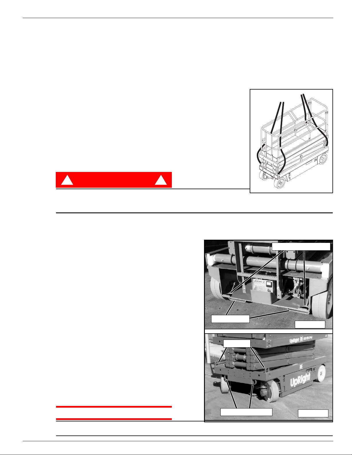
PreparationforShipment .................................................................... 13
LiftingByCrane............................................................................ 13
ByForklift ................................................................................ 13
DrivingorWinchingontoaTruckorTrailer....................................................... 13
Maintenance........................................................................14
BlockingTheElevatingAssembly.............................................................. 14
BatteryMaintenance........................................................................ 15
InspectionandMaintenanceSchedule...................................................16
Daily Preventative Maintenance Checklist................................................16
Labels .............................................................................17
Specifications.......................................................................19
X20N,X20WandX26N................................................................... 9
X32N ................................................................................. 9
LoweringProcedure..................................................................... 10
RaisingProcedure...................................................................... 10
FoldDownProcedure ................................................................... 11
Erection Procedure . . . .................................................................. 11
ScissorBraceInstallation................................................................. 14
ScissorBraceStowage .................................................................. 14
BatteryCharging ....................................................................... 15
Page 2 Operation Manual
Introduction 060572-027 X Series
I
NTRODUCTION
This manual covers operation of the X Series Self-Propelled Work Platforms. This manual must be
stored on the machine at all times.
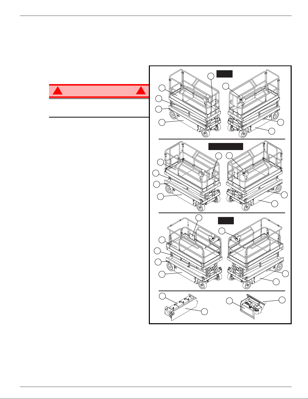
G
ENERAL
D
ESCRIPTION
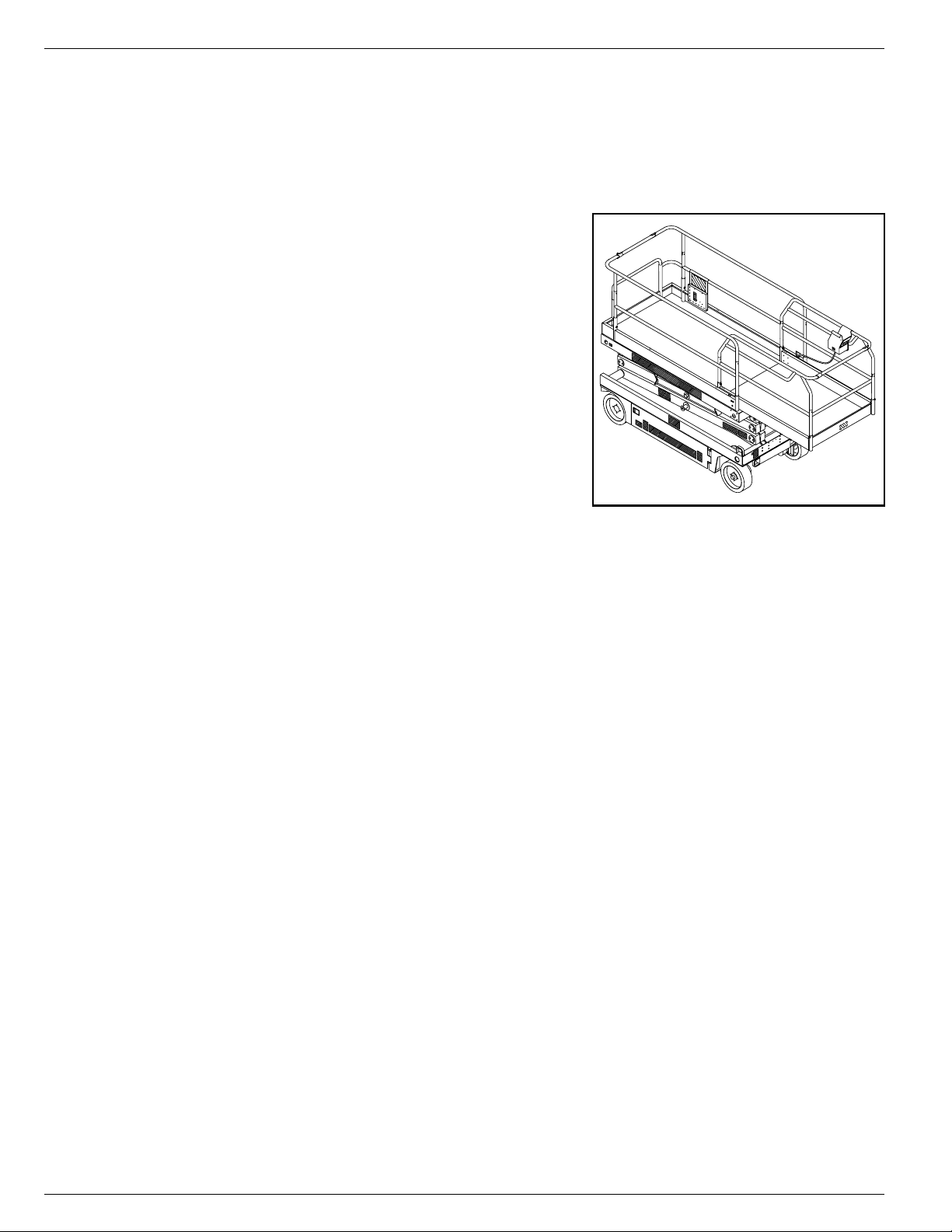
1. Platform
!
WARNING
DO NOT use the maintenance platform
without guardrails properly assembled
and in place
2. Elevating Assembly
3. Chassis
4. Power Module
5. Control Module
6. Platform Controls
7. Manual Case
8. Chassis Controls
9. Hydraulic Fluid Reservoir
10. Batteries
Figure 1:
X20N
7
1
6
XSeries
!
2
3
4
X20W & X26N
6
7
1
2
3
4
8
5
8
5
7
1
2
3
4
10
4
X32N
6
9
8
5
5
Operation Manual Page 3
060572-027 X Series Special Limitations
S
PECIAL
L
IMITATIONS
Travel with the platform raised is limited to creep speed range.
Elevating the Work Platform is limited to firm, level surfaces only.
DANGER
! !
The elevating function shall ONLY be used when the work platform is level and on a firm surface.
The work platform is NOT intended to be driven over uneven, rough, or soft terrain.
P
LATFORM
The maximum capacity for the MACHINE, including occupants is determined by model and options, and
is listed in “Specifications” on page 20.
DANGER
! !
DO NOT exceed the maximum platform capacity or the platform occupancy limits for this machine.
M
ANUAL
Manual force is the force applied by the occupants to objects such as walls or other structures outside the
work platform.
F
ORCE
C
APACITY
The maximum allowable manual force is limited to 200 N (45 lbs.) of force per occupant, with a maximum
of 400 N (90 lbs.) for two or more occupants.
DANGER
! !
DO NOT exceed the maximum amount of manual force for this machine.
B
EAUFORT
Never operate the machine when wind speeds exceed 25 km/h (15 mph) [Beaufort scale 4].
BEAUFORT
RATING
3 3,4~5,4 12,25~19,4 11.5~17.75 7.5~12.0 Papers and thin branches move, flags wave.
4 5,4~8,0 19,4~28,8 17.75~26.25 12.0~18 Dust is raised, paper whirls up,and small branches sway.
5 8,0~10,8 28,8~38,9 26.25~35.5 18~24.25 Shrubs with leaves start swaying. Wave crests are apparent in ponds or swamps.
6 10,8~13,9 38,9~50,0 35.5~45.5 24.5~31 Tree branches move. Power lines whistle. It is difficult to open an umbrella.
7 13,9~17,2 50,0~61,9 45.5~56.5 31.~38.5 Whole trees sway. It is difficult to walk against the wind.
m/s km/h ft/s mph
L
IFT
O
VERLOAD
All models include a feature that alerts the operator when the platform load is exceeded. If the alarm
sounds during the lift function, lower the platform and reduce the platform load.
DANGER
! !
S
WIND SPEED
CALE
A
LARM
GROUND CONDITIONS
Never operate the machine with a platform load greater than the rated capacity.
Page 4 Operation Manual
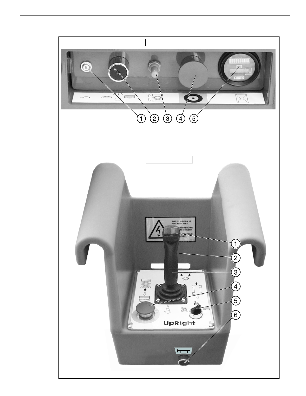
Controls and Indicators 060572-027 X Series
C
ONTROLS AND
I
NDICATORS
Chassis Controls
1 Circuit Breaker
2. Chassis Key Switch
3. Chassis Lift/Lower Switch
4. Chassis Emergency Stop Button
5. Hour Meter/Voltage Indicator
Platform Controls
Figure 2:
Controls and Indicators
1. Steering Switch
2. Interlock Switch (on front
of Control Handle)
3. Control Handle
4. Platform Emergency Stop
Switch
5. Lift Drive Selector Switch
6. Horn Button
Operation Manual Page 5

060572-027 X Series Pre-Operation Safety Inspection
P
RE
-O
PERATION
NOTE: Carefully read, understand and follow all safety rules, operating instructions, labels and National Safety
Instructions/Requirements. Perform the following steps each day before use.
1. Open modules and inspect for damage, fluid leaks or missing parts.
2. Check the level of the hydraulic fluid with
the platform fully lowered. The hydraulic
reservoir is located in the Control Module Door. The fluid level must be
between the MIN and MAX lines. Add
hydraulic fluid if necessary.
3. Check that fluid level in the batteries is
correct.
4. Verify that batteries are charged.
5. Check that A.C. extension cord has
been disconnected from the plug in the
rear of the machine.
6. Check that all guardrails are in place
and all fasteners are properly tightened.
7. Inspect the machine thoroughly for
cracked welds and structural damage,
loose or missing hardware, hydraulic
leaks, damaged control cable, loose wire connections and wheel bolts.
S
AFETYINSPECTION
Figure 3:
Hydraulic Tank
Page 6 Operation Manual

System Function Inspection 060572-027 X Series
S
YSTEM
F
UNCTION
Refer to Figure 2 for the locations of various controls and indicators.
I
NSPECTION
!
WARNING
STAND CLEAR of the work platform while performing the following checks.
Before operating the work platform, survey the work area for surface hazards such as holes, drop-offs,
bumps and debris.
Check in ALL directions, including above the work platform, for obstructions and electrical conductors.
Protect the control console cable from possible damage while performing checks.
1. Move the machine, if necessary, to an unobstructed area to allow for full elevation.
2. Pull Chassis Emergency Stop Switch to the ON position.
3. Pull Platform Emergency Stop Switch to the ON position.
4. Turn and hold the Chassis Key Switch to CHASSIS. Push the Chassis Lift/Lower Switch to the UP posi-
tion and raise the platform approximately 2,1 m (7 feet). BLOCK THE ELEVATING ASSEMBLY AS
DESCRIBED ON PAGE 9.
5. Visually inspect the elevating assembly, lift cylinder, cables, and hoses for cracked welds and structural
damage, loose hardware, hydraulic leaks, loose wire connections, and erratic operation. Check for missing or loose parts.
6. Verify that the Depression Mechanism Supports have rotated into position under the machine. REMOVE
THE SCISSOR BRACE AS DESCRIBED ON page 14.
7. Turn and hold the Chassis Key Switch to CHASSIS. Push the Chassis Lift/Lower Switch to the UP position and fully elevate the platform.
8. Partially lower the platform by pushing Chassis Lift/Lower Switch to LOWER, and check for proper operation of the audible lowering alarm.
9. Open the Emergency Lowering Valve (see Figure 5) by pulling the knob out to check for proper operation. When the platform is lowered, release the knob.
10. Push the Chassis Emergency Stop Switch to check for proper operation. All machine functions should
be disabled. Pull out the Chassis Emergency Stop Switch to resume.
11. Turn the Chassis Key Switch to DECK.
12. Check that the route is clear of obstacles (persons, obstructions, holes, and drop-offs, bumps and
debris), is level, and is capable of supporting the wheel loads.
13. Mount the platform and properly close the entrance.
14. Turn the Drive/Lift Switch to DRIVE.
!
NOTE: Use both HI and LOW drive (if applicable) when performing the following step.
15. While engaging the Interlock Switch, move the Control Handle to FORWARD, then REVERSE, to check
for speed control.
16. Push the Steering Switch RIGHT, then LEFT, to check for steering control.
17. Turn the Drive/Lift Switch to LIFT. Grasp the Control Handle, engaging the Interlock Switch, and push it
forward to check platform lift controls. Raise the platform to full elevation.
18. Pull back on the Control Handle. The platform should descend and the audible lowering alarm should
sound.
19. Push the Platform Emergency Stop Switch to check for proper operation. All machine functions should
be disabled. Pull out the Platform Emergency Stop Switch to resume.
Operation Manual Page 7
060572-027 X Series Operation
O
PERATION
Before operating the work platform, ensure that the Pre-Operation Safety Inspection has been completed
and that any deficiencies have been corrected. Never operate a damaged or malfunctioning machine.
The operator must be thoroughly trained on this machine.
P
LATFORM
1. Mount the platform and properly close the entrance.
2. Depress the foot lever located at the rear of the platform
extension. Push the platform extension forward until the
pin engages the front stop.
3. To retract the platform extension, depress the foot lever
and pull the platform extension toward the rear of the
machine until the pin engages the rear stop.
T
RAVEL
L
OWERED
1. Check that the route is clear of obstacles (persons,
obstructions, holes, drop-offs, bumps, and debris), is level,
and is capable of supporting the wheel loads.
2. Verify that the Chassis Key Switch is turned to DECK and
the Chassis Emergency Stop Switch is ON (pulled out).
3. Mount the platform and properly close the entrance.
4. Check clearances above, below, and to the sides of platform.
5. Pull the Platform Emergency Stop Switch out to the ON position.
6. Turn the Drive/Lift Switch to DRIVE.
E
W
ITH THE
XTENSION
P
LATFORM
Figure 4:
Platform Extension
NOTE: Turn Lift/Drive SwitchtoHI (if applicable) for traveling onlevel ground, or to LOW when extra torque is required
for climbing grades.
7. Engage the Interlock Switch and move the Control Handle to FORWARD or REVERSE to travel in the
desired direction. The speed of the machine will vary depending on how far from center the Control
Handle is moved.
S
TEERING
1. Turn the Drive/Lift Switch to DRIVE.
2. While engaging the Interlock Switch, push the Steering Switch to RIGHT or LEFT to turn the wheels in
the desired direction. Observe the tires while maneuvering the work platform to ensure proper direction.
NOTE: Steering is not self-centering. Wheels must be returned to the straightahead position by operating the Steering
Switch.
E
LEVATING THE
1. Select a firm, level surface.
2. Turn the Drive/Lift Switch to LIFT.
3. While engaging the Interlock Switch, push the Control Handle forward.
4. If the machine is not level the tilt alarm will sound and the machine will not lift or drive. If the tilt alarm
sounds the platform must be lowered and the machine moved to a firm level surface before
attempting to re-elevate the platform.
P
LATFORM
NOTE: Depression Mechanism supports will deploy automatically as the platform elevates and will retract after the
platform has been lowered completely and has been driven.
Page 8 Operation Manual
Operation 060572-027 X Series
T
RAVEL
NOTE: The machine will travel at reduced speed when the platform is elevated.
1. Check that the route is clear of obstacles (persons, obstructions, holes, drop-offs, bumps, and debris), is
level, and is capable of supporting the wheel loads.
2. Check clearances above, below, and to the sides of platform.
3. Turn the Drive/Lift Switch to DRIVE.
4. Engage the Interlock Switch and move the Control Handle to FORWARD or REVERSE to travel in the
desired direction. The speed of the machine will vary depending on how far from center the Control Handle is moved.
5. If the machine is not level the tilt alarm will sound and the machine will not lift or drive. If the tilt alarm
sounds the platform must be lowered and the machine moved to a firm, level surface before
attempting to re-elevate the platform.
L
OWERING THE
1. Turn the Drive/Lift Switch to LIFT.
2. Check around the base of the platform to ensure that no one is in contact with the machine. Engage the
Interlock Switch and pull back on the Control Handle to lower the platform.
3. The platform will stop when it reaches the PPE cutout height. Inspect around the machine to ensure no
one is in contact with the machine. After a four-second time delay, lower the platform as in step 2.
W
ITH THE
P
LATFORM
P
LATFORM
E
LEVATED
E
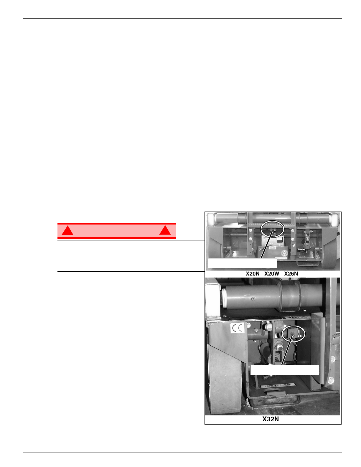
MERGENCY
!
WARNING
If the platform should fail to lower, NEVER climb
down the elevating assembly.
Stand clear ofthe elevating assembly while operating
the Emergency Lowering Valve Knob.
X20N, X20W
The Emergency Lowering Valve for the X20N,
X20W, and X26N is located at the rear of the
machine, above the charger.
1. Open the Emergency Lowering Valve by pulling
and holding the knob.
2. To close, release the knob. The platform will not
elevate if the Emergency Lowering Valve is open.
L
OWERING
AND
X26N
!
X32N
The emergency lowering control switch is located at
the rear of the machine.
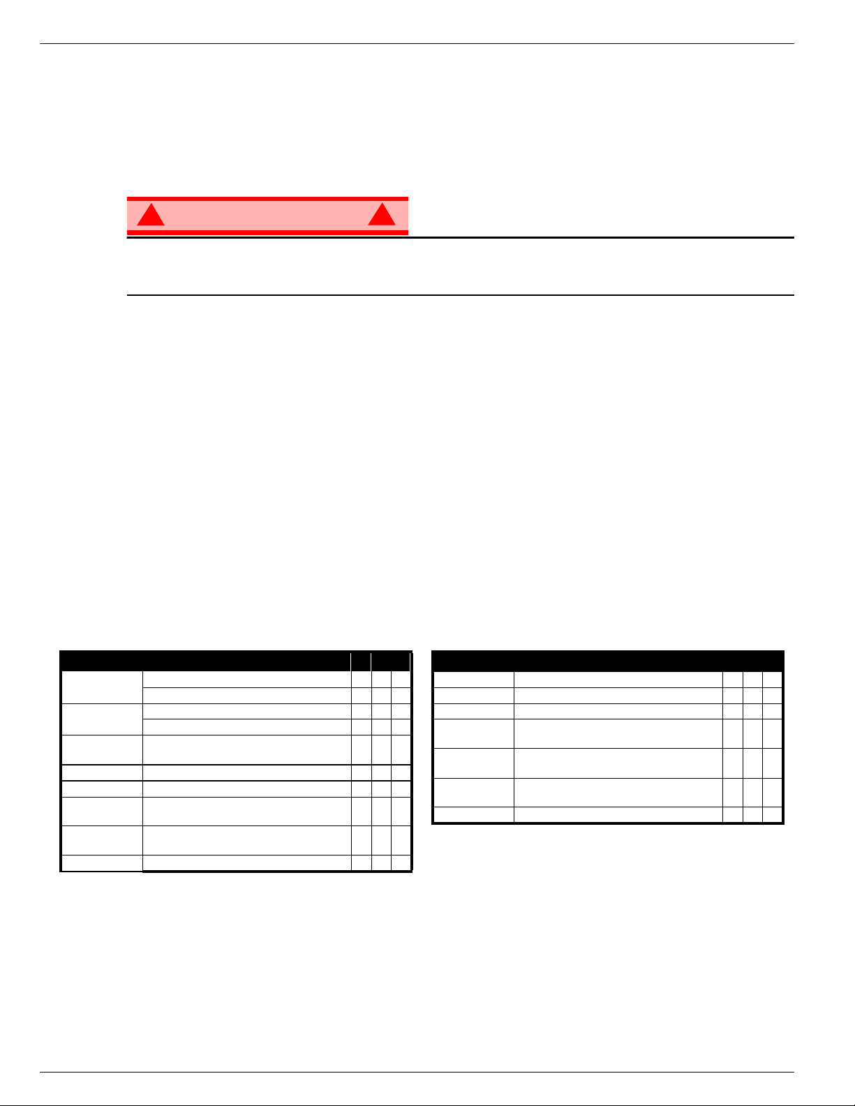
Figure 5:
Emergency Lowering Knob
Emergency Lowering Switch
Emergency Lowering Valve
1. Open the emergency lowering valve by pushing
down on the toggle switch and holding it.
2. Once the platform is fully lowered, release the
toggle switch to close the valve. The platform will
not elevate if the Emergency Lowering Valve is
open.
Operation Manual Page 9

060572-027 X Series Operation
L
OWER THE
This procedure applies only to the X26N model for the purpose of passing through a standard double
doorway. Guardrails must be returned to proper position before using the machine.
L
OWERINGPROCEDURE
1. Ensure that the slide-out deck extension is fully retracted and the deck pin is locked. Place the Platform
Controls on the floor of the platform.
2. Remove and retain the set screws from the side guardrails and the slide-out deck guardrails.
3. Lower the slide-out deck guardrail completely.
4. Lower the rear guardrail until it rests on the stop screws.
5. Lower the side guardrails completely.
6. Raise the rear guardrail until the retaining pins engage. Remove and retain the stop screws and nuts
from the rear guardrail.
7. Pull the two retaining pins and lower the rear guardrail completely.
R
AISINGPROCEDURE
1. Raise the rear guardrail until the retaining pins engage.
2. Install the stop screws and nuts on the rear guardrail and torque to 42 N-m (31 ft. lbs).
3. Pull the two retaining pins and lower the rear guardrail until it rests on the stop screws.
4. Raise the side guardrails until the tops are level with the rear guardrail.
• Install the set screws
5. Raise the slide-out deck guardrail until the top is level with the side guardrails.
• Install the set screws
6. Hang the controller on the slide-out deck guardrail.
7. Torque all set screws to 42 N-m (31 ft. lbs).
G
UARDRAILS
, X26N
!
WARNING
Before operating machine, guardrails must be securely fastened in their proper position.
!
Page 10 Operation Manual

Operation 060572-027 X Series
F
OLD
This procedure applies only to the X32N model for the purpose of passing through a standard double doorway. Guardrails must be returned to proper position before using the machine.
F
OLDDOWNPROCEDURE
1. Unhook the controller from the side guardrail and place it on the floor of the platform.
2. Pull the retaining pin on the front guardrail and rotate inwards.
3. Pull the retaining pin on the rear guardrail and rotate inwards.
4. Starting with the slide-out deck guardrails and then the outer guardrails, lift up on each guardrail and fold
E
RECTIONPROCEDURE
1. Starting with the outer guardrails and then the slide-out deck guardrails, raise each guardrail and drop it
2. Rotate the front and rear upper guardrails outward and secure them to the opposite side guardrails,
3. Hang the controller on the side guardrail.
D
OWN GUARDRAILS
inward.
down, securing it in the vertical position.
using the retaining pins.
, X32N
Operation Manual Page 11
060572-027 X Series Towing or Winching
T
OWING OR
Perform the following only when the machine will not operate under its own power and it is necessary to
move the machine or when winching onto a transport vehicle (see “Transporting the Work Platform” on
page 13).
W
INCHING
CAUTION
DO NOT tow or winch the machine faster than 0,3 m/s (1ft./s). Faster speeds will damage drive
components and void the warranty.
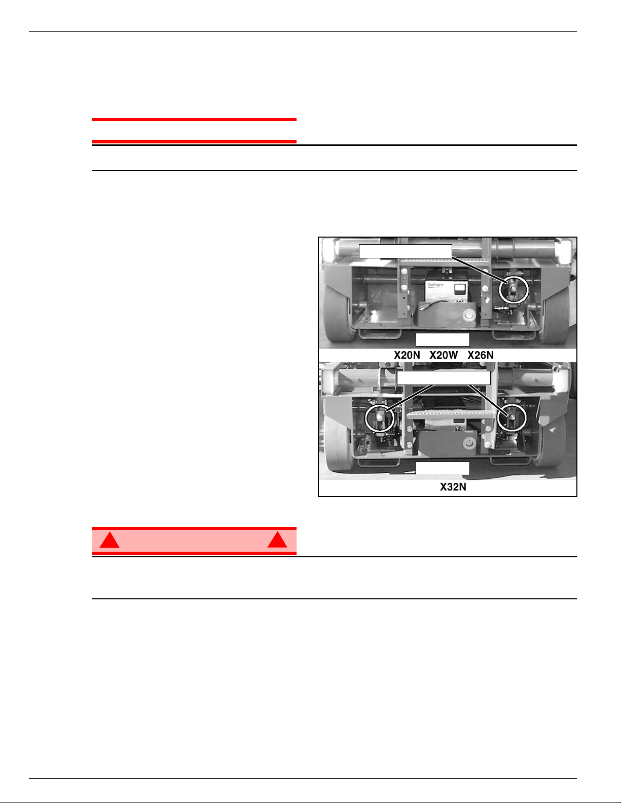
P
ARKING
Perform the following procedure only when the machine will not operate under its own power and it is necessary to move the machine, or when winching onto a trailer to transport.
B
RAKE
R
ELEASE
Figure 6:
Parking Brake Release
NOTE: X32N models have two identical brake
adjustment nuts located on both sides of the
ladder. The X20N, X20W, and X26N have only
one.
The Brake Adjustment/Release Nut(s) is/are
located at the rear of the machine to the right
and/or left of the ladder.
1. To release the brakes turn the nut(s) counterclockwise until the brakes disengage the
tires.
2. The machine will now roll when pushed or
pulled.
3. To re-engage the brakes, turn the nut(s)
clockwise until the brakes have fully
engaged the tires. Verify that the brakes
have fully engaged the rear tires before
operating the machine by testing their abilitytoholdthemachineona22% grade
(X32N 20%).
!
WARNING
!
Parking Brake Release
REAR
Parking Brake Release
REAR
Never tow faster than 0,3 m/sec. (1 ft./sec.).
Never operate the work platform with the parking brakes released. Serious injury or damage could
result.
A
FTER
1. Ensure that the platform is fully lowered.
2. Park the machine on a firm level surface, preferably under cover, secure against vandals, children and
unauthorized operation.
3. Turn the Chassis Key Switch to OFF and remove the key to prevent unauthorized operation.
Page 12 Operation Manual
U
SE
E
ACH
D
AY
Transporting the Work Platform 060572-027 X Series
T
RANSPORTING THE
P
REPARATION FOR
1. Fully lower the platform.
2. Disconnect the battery negative (-) lead from the battery terminal.
3. Band the controller to the front guardrail.
4. Band the elevating linkage to the frame.
L
IFTING
1. Secure straps to chassis tie down/lifting lugs only.
2. Place the platform onto the transport vehicle in transport position.
3. Chock the wheels.
4. Secure the work platform to the transport vehicle with chains or straps
of adequate load capacity attached to the chassis tie down/lifting lugs.
B
Y
F
B
Y
ORKLIFT
C
RANE
W
ORK
S
P
LATFORM
HIPMENT
Figure 7:
Secure Crane Straps
DANGER
! !
Forklifting is for transport only.
See specifications for weight of work platform and be certain that forklift is of adequate capacity to lift
the work platform.
Forklift from the rear of the machine using the forklift pockets provided. If necessary, the machine may be
forklifted from the side by lifting under the Chassis Modules.
Transporting the Work Platform
Rear Tie Down/Lift Lugs
REAR
D
RIVING OR
T
RUCK OR
NOTE: Do not winch faster than 0,3 m/s
1. Move the machine onto the truck or trailer;
A. To
B. To
2. Secure the work platform to the transport vehicle
Drive
a. Move the work platform up the ramp and into
transport position.
b. Set the wheels straight and turn off the machine.
c. Chock the wheels.
Winch
a. Move the work platform up to the ramp.
b. Attach the winch cable to the tie down/lifting lugs.
c. Release the parking brakes (refer to “Towing or
Winching” on page 12).
d. Winch the platform into transport position
e. Chock the wheels.
with chains or straps of adequate load capacity
attached to the chassis tie down/lifting lugs.
W
INCHING ONTO A
T
RAILER
(1 ft/s)
.
the machine onto the transport vehicle:
the machine onto the transport vehicle:
Figure 8:
Forklift Pockets
Lift Lugs
CAUTION
Overtightening of the chains or straps attached to the
Tie Down/Lifting Lugs may result in damage to work platform.
Operation Manual Page 13
Front Tie Down Lugs
FRONT

060572-027 X Series Maintenance
M
AINTENANCE
!
WARNING
!
Never perform service while the platform is elevated without first blocking the elevating assembly.
DO NOT stand in the elevating assembly area while deploying or storing the brace.
Figure 9:
B
LOCKING
A
SSEMBLY
S
CISSORBRACEINSTALLATION
1. Park the work platform on a firm, level surface.
2. Pull Chassis EMERGENCY STOP Switch to the ON position.
3. Pull Platform EMERGENCY STOP Switch to the ON position.
4. Turn and hold the Chassis Key Switch to CHASSIS.
5. Push the Chassis Lift/Lower Switch to LIFT to elevate the
platform until the Scissor Brace can be rotated to the vertical
position.
6. X20N, X20W, and X26N – From the rear of the machine, lift
the Scissor Brace from its stowed position. Rotate upward
and outward, then down until it is hanging vertically below its
attachment point.
7. X32N – From the left side of the machine, pull the locking
pin securing the brace. Rotate the Scissor Brace counterclockwise until it is in the vertical position.
8. Lower the platform by pushing the Chassis Lift/Lower Switch
to LOWER and gradually lower the platform until the Scissor
Brace is supporting the platform.
T
HE
E
LEVATING
Rotate Brace
Clockwise to
X20N, X20W, and X26N
Pin Rests on Brace
when in Blocking
Position
Scissor Brace
Block
Brace Rests on
Weldmentwhen
in Blocking
Position
S
CISSORBRACE
1. Using the Chassis Controls, gradually elevate the platform
until the Scissor Brace is clear.
2. X20N, X20W, and X26N – Rotate the Scissor Brace outward
and upward over its mounting point until it rests in the
stowed position.
3. X32N – Rotate the Scissor Brace clockwise until the locking
pin engages.
4. Lower the platform by pushing the Chassis Lift/Lower Switch
to LOWER to completely lower the platform.
Page 14 Operation Manual
S
TOWAGE
Scissor Brace in
Rest Position
Brace Rotates to
Blocking Position
Brace Rests on Pin
when in Blocking
Position
X32N
Maintenance 060572-027 X Series
B
ATTERY
M
AINTENANCE
!
WARNING
!
Hazard of explosive gas mixture. Keep sparks, flame, and smoking material away from batteries.
Always wear safety glasses when working near batteries.
Battery fluid is highly corrosive. Thoroughly rinse away any spilled fluid with clean water.
Always replace batteries with UpRight batteries or manufacturer approved replacements weighing
26,3 kg (58 lbs.) each.
• Check the battery fluid level daily, especially if the work platform is being used in a warm, dry climate.
• If electrolyte level is lower than 10 mm (
tap water with high mineral content, as it will shorten battery life.
• Keep the terminals and tops of the batteries clean.
• Refer to the Service Manual to extend battery life and for complete service instructions.
B
ATTERYCHARGING
Charge the batteries at the end of each work
shift or sooner if the batteries have been discharged.
!
WARNING
3
in.) above the plates add distilled water only. DO NOT use
/
8
Figure 10:
Battery Charger
!
Charge the batteries in a well ventilated area.
Do not charge the batteries when the work
platform is near a source of sparks or flames.
Permanent damage to the batteries will result if
the batteries are not immediately recharged after
Charger Plug
(behind plate)
Charger
REAR
discharging.
Never leave the battery charger operating for more than two days.
Never disconnect the cables from the batteries when the charger is operating.
Keep the charger dry.
1. Check the battery fluid level. If the battery fluid level is lower than 10 mm (
distilled water only.
2. Connect an appropriate extension cord to charger outlet plug in Left Module Door. Plug the extension
cord into a properly grounded outlet of proper voltage and frequency.
3. The charger turns on automatically after a short delay. The LED charge indicator will illuminate. After
completion of the charge cycle the LED will blink, indicating that the charger is in a continuing maintenance mode. DO NOT leave the charger plugged in for more than 48 hours, as permanent damage to
the batteries may occur.
NOTE: The battery charger circuit must be used with a GFI (Ground Fault Interrupt) outlet.
NOTE: DO NOT operate the machine while the charger is plugged in.
3
in.) above the plates add
/
8
Operation Manual Page 15
060572-027 X Series Inspection and Maintenance Schedule
I
NSPECTION AND
M
AINTENANCE
S
CHEDULE
The Complete Inspection consists of periodic visual and operational checks, along with periodic minor
adjustments that assure proper performance. Daily inspection will prevent abnormal wear and prolong the
life of all systems. The inspection and maintenance schedule should be performed at the specified intervals. Inspection and maintenance shall be performed by personnel who are trained and familiar with
mechanical and electrical procedures.
D
AILY
M
AINTENANCE
Y = Yes/Acceptable
N = No/Not Acceptable
R = Repaired/Acceptable
!
WARNING
!
Before performing preventative maintenance, familiarize yourself with the operation of the machine.
Always block the elevating assembly whenever it is necessary to perform maintenance while the
platform is elevated.
The daily preventative maintenance checklist has been designed for machine service and maintenance.
Please photocopy this page and use the checklist when inspecting the machine.
P
REVENTATIVE
T
ABLEKEY
M
AINTENANCE
C
HECKLIST
P
REVENTATIVEMAINTENANCE
R
EPORT
Date:_______________________________________
Owner: _____________________________________
Model No:___________________________________
Serial No: ___________________________________
COMPONENT INSPECTIONOR SERVICES Y N R
Battery
Chassis
Control Cable
Controller Check switch operation.
Drive Motors Check for operationand leaks.
Elevating
Assembly
Emergency
Lowering System
Entire Unit Check for and repair collision damage.
Check electrolyte level.
Check battery cable condition.
Check hoses for pinch or rubbing points.
Check welds for cracks.
Check theexterior of the cable for pinching,
binding or wear.
Inspect for structural cracks.
Operate the emergency lowering valve and check
for serviceability.
Serviced By: _________________________________
COMPONENT INSPECTION OR SERVICES Y N R
Hydraulic Fluid Check fluid level.
Hydraulic Pump Check for hose fitting leaks.
Hydraulic System Check for leaks.
Labels
PlatformDeck
and Rails
PlatformDeck
and Rails
Tires and Wheels Check for damage.
Check for peeling, missing, or unreadable labels
& replace.
Check welds for cracks.
Check condition of deck.
Page 16 Operation Manual

Daily Preventative Maintenance Checklist 060572-027 X Series
N
OTES
:
Operation Manual Page 17
060572-027 X Series Labels
MAX = 113 kg =
+
1
066561-902
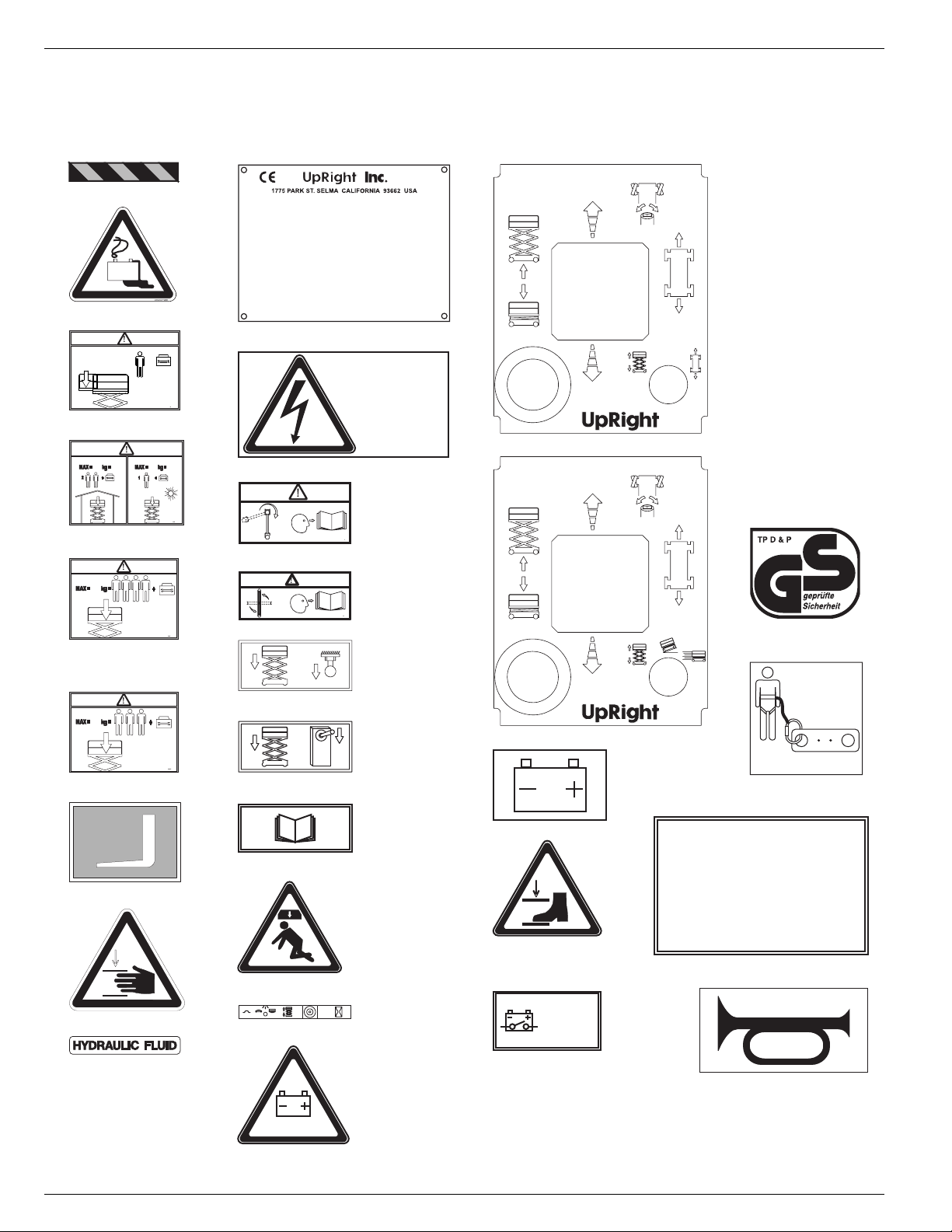
L
ABELS
These labels shall be present and in good condition before operating the work platform. Be sure to read,
understand and follow these labels when operating the work platform.
3 064936-099
4 101210-000
!
1
MAX = 113 kg =
5 066551-950
+
066551-950
!
340
340
066557-951
066557-930
6 X20N 066557-930
!
454
066557-951
066557-954
6 X20W, 26N
066557-957
!
340
Model______________ Serial number:___________
Machine weight _______kg Mfg. date:_________
Maximum wheel load:________
Maximum allowable incline of machine when elevated:_____deg.
Occupants and equipment must not exceed the rated maximum
load:_____kg Maximum platform occupants: _____
Maximum allowable sIde force on platform:_____N
Maximum platform height:______m
Maximum platform reach:______m
Maximum allowable wind speed: ______m/s=Beaufort scale_____
Maximum hydraulic system pressure:_____bar
Maximum system voltage: _______Vdc
This machine is manufactured to comply with
Machinery directive 89-392/CEE
CAUTION: CONSULT OPERATOR'S MANUAL BEFORE USE.
061205-003
11 061205-003
THIS PLATFORM IS
NOT INSULATED
DIESE ARBEITSBÜHNE
IST NICHT ISOLIERT
CETTE PLATEFORME
N'EST ISOLEE
100102-900
15 100102-900
!
066561-900
16 X20N, 20W, 26N 066561-900
!
066561-902
16 X32N 066561-902
005223-906
17 X20N, 20W, 26N 005223-906
31 X20N 101222-904
35 030768-002
31 X20W, 26N, 32N 101222-905
066557-951
066557-950
6 X32N 066557-950
014222-903
7 014222-903
17 X32N 005223-908
20 010076
005223-908
36 068635-001
066522-900
32 066522-900
010076-901
33 101208-001
USE OF THE AERIAL WORK PLATFORM: This aerial work platform is intended to lift persons and his tools as well as the material
used for the job. It is designed for repair and assembly jobs and assignments at overhead workplaces (ceilings, cranes, roof
structures, buildings etc.). All other uses of the aerial work platform are prohibited!
THIS AERIAL WORK PLATFORM IS NOT INSULATED! For this reason it is imperative to keep a safe distance
from live parts of electrical equipment!
Exceeding the specified permissible maximum load IS PROHIBITED! Read operator's manual for more details.
The use and operation of the aerial work platform as a lifting tool or a crane IS PROHIBITED!
NEVER exceed the manual force allowed for this machine. Read operator's manual for more details.
DISTRIBUTE all platform loads evenly on the platform.
NEVER operate the machine without first surveying the work area for surface hazards such as holes, drop-offs, bumps, curbs,
or debris; and avoiding them.
OPERATE machine only on surfaces capable of supporting wheel loads.
NEVER operate the machine when wind speeds exceed this machine's wind rating. Read operator's manual for more details.
IN CASE OF EMERGENCY push emergency stop switch to deactivate all powered functions.
IF ALARM SOUNDS while platform is elevated, STOP, carefully lower platform. Move machine to a firm, level surface.
Climbing up the railing of the platform, standing on or stepping from the platform onto buildings or other structures, IS PROHIBITED!
Dismantling the swing gate or other railing components IS PROHIBITED! Always make certain that the swing gate is closed
and securely locked!
IT IS PROHIBITED to keep the swing gate or liftable bar in an open position when the platform is raised!
To extend the height or the range by placing of ladders, scaffolds or similar devices on the platform IS PROHIBITED!
NEVER perform service on machine while platform is elevated without blocking elevating assembly.
INSPECT the machine thoroughly for cracked welds, loose or missing hardware, hydraulic leaks, loose wire connections,
and damaged cables or hoses before using.
VERIFY that all labels are in place and legible before using.
NEVER use a machine that is damaged, not functioning properly, or has damaged or missing labels.
To bypass any safety equipment IS PROHIBITED and presents a danger for the persons on the aerial work platform and in its working range.
NEVER charge batteries near sparks or open flame. Charging batteries emit explosive hydrogen gas.
Modifications to the aerial work platform are prohibited or permissible only at the approval by UpRight.
AFTER USE, secure the work platform from unauthorized use by turning the keyswitch off and removing key.
37 067195-001
25 066556-900
INSIDE
9 101208-000
10 060197-000
26 066559-900
34 107051-900
INNSEITIG
L'INTERIEUR
107051-900
40 107053-000
26,3 kg +
29 062562-951
Page 18 Operation Manual
 Loading...