

Page 1
kÉï=~ë=çÑW
MVKOMMV
H
`OHI=jN
fелн~дд~нбзе=oЙимбкЙгЙенл= =
bеЦдблЬ
Page 2

General information Sirona Dental Systems GmbH
Installation Requirements
General information
About this document
This document describes the installation requirements for
+
the C2
, M1+ dental treatment centers.
Their subsequent installation is described in the Installation
Instructions REF 59 58 470 (C2
(M1+).
Besides you need the drilling template, REF 58 71 673, for
secure fastening of the treatment center to the floor.
+
) and REF 59 91 059
MVKOMMV
Changes since the last version 06.2007:
Chapter or section, page
1.4 Underfloor installation of SIVISION connections .. 11
2.1 Dimensions of the C2+ 1:20 ................................. 16
2.2 Dimensions of the M1+ 1:20 ................................. 19
3.1 Accessories .......................................................... 24
60 27 911 D3370
2 D3370.021.02.07.02
Page 3

Sirona Dental Systems GmbH List of Contents
Installation Requirements C2
+
, M1
+
List of Contents
1 Preparations.......................................................................................................................... 5
1.1 Safety........................................................................................................... 6
1.2 Media quality................................................................................................ 7
1.3 Supply lines in the termination panel ........................................................... 8
1.4 Underfloor installation of SIVISION connections ......................................... 11
1.5 Mounting plates ........................................................................................... 12
2 Dimensions, technical data ................................................................................................. 15
2.1 Dimensions of the C2+ 1:20 ......................................................................... 16
2.2 Dimensions of the M1
2.3 Technical data ............................................................................................. 22
3 Electromagnetic compatibility ............................................................................................ 23
3.1 Accessories ................................................................................................. 24
3.2 Electromagnetic emission............................................................................ 25
3.3 Immunity to interference.............................................................................. 26
3.4 Working clearances ..................................................................................... 28
+
1:20......................................................................... 19
bеЦдблЬ
60 27 911 D3370
D3370.021.02.07.02
3
Page 4

List of Contents Sirona Dental Systems GmbH
Installation Requirements C2
+
, M1
+
60 27 911 D3370
4 D3370.021.02.07.02
Page 5
1 Preparations
C2+, M1+
1.1 Safety .................................................................................................................................... 6
1.2 Media quality ......................................................................................................................... 7
1.3 Supply lines in the termination panel ..................................................................................... 8
1.4 Underfloor installation of SIVISION connections ................................................................... 11
1.5 Mounting plates ..................................................................................................................... 12
bеЦдблЬ
60 27 911 D3370
D3370.021.02.07.02
5
Page 6
1 Preparations Sirona Dental Systems GmbH
ATTENTION
ATTENTION
ATTENTION
ATTENTION
ATTENTION
ATTENTION
ATTENTION
ATTENTION
Installationsvoraussetzungen C2
+
, M1
1.1 Safety
+
It is essential that you comply with the warning and safety
information contained in the Installationsvoraussetzungen.
All such information is highlighted by the captions NOTE,
ATTENTION, and CAUTION.
For reasons of product safety, only original Sirona accessories approved for this product, or accessories from third parties approved by Sirona, may be used. The user is responsible for dangers resulting from the use of non-approved
accessories.
If any devices not approved by Sirona are connected, they
must comply with the applicable standards, e.g.:
• IEC 60950 for information technology equipment and
• IEC IEC 60601-1 for medical electrical equipment
In case of doubt, contact the manufacturer of the system
components.
Any person who assembles or modifies a medical electrical
system complying with the standard IEC 60 601-1-1 (safety
requirements for medical electrical equipment) by combining it with other equipment (e.g. when connecting a PC) is
responsible for ensuring that the requirements of this regulation are met to their full extent for the safety of the patients,
the operators and the environment.
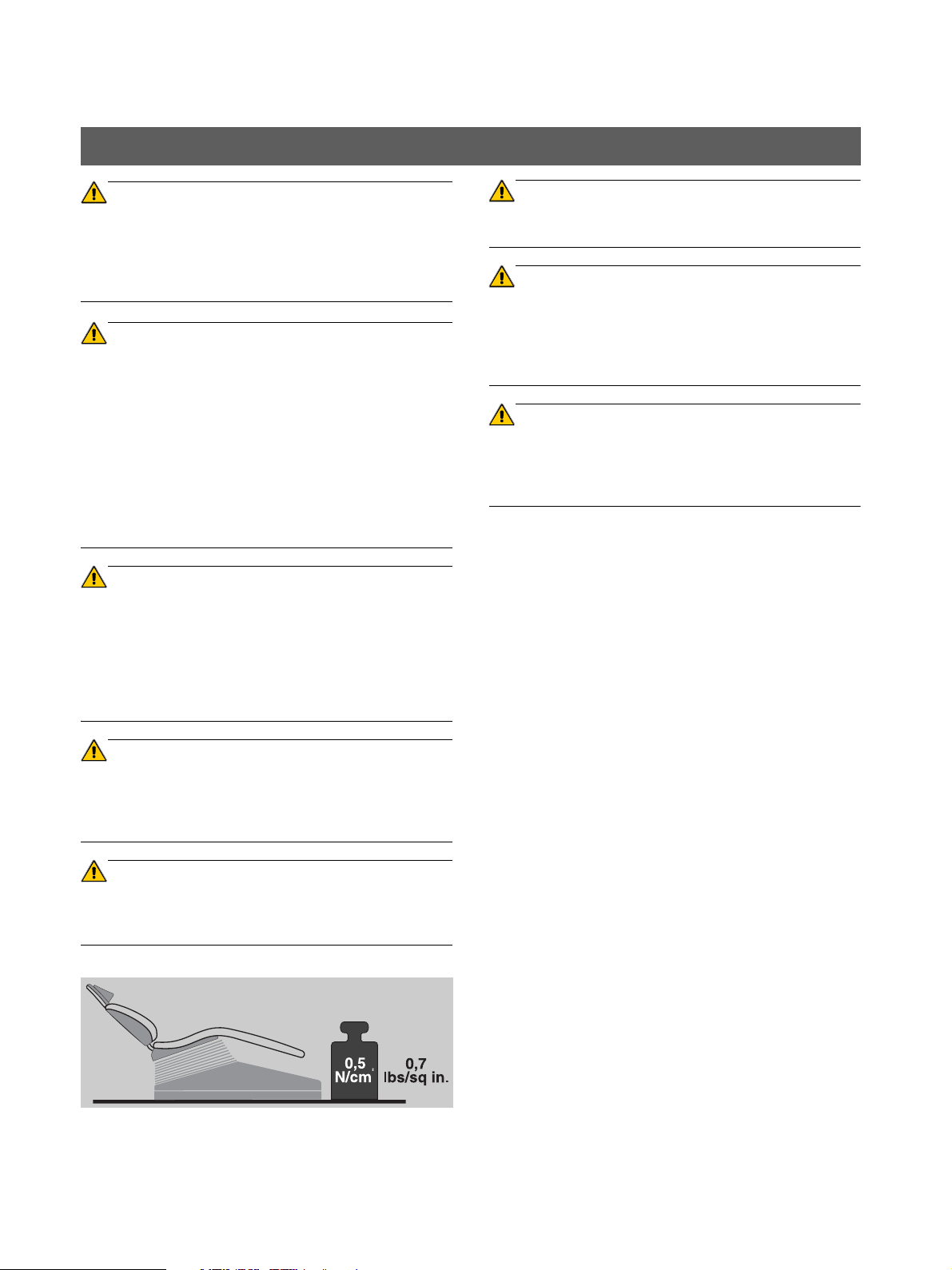
The floor must have a minimum loading capacity of 0.5N/
cm².
Interference of electromedical devices caused by radio telephones:
To ensure the operational readiness of electromedical devices, the use of mobile radio telephones in the practice or
hospital area is prohibited.
Electromagnetic compatibility: The unit should not be operated in the immediate vicinity of other devices. If this
proves to be unavoidable, the unit should be monitored to
ensure that it is used properly.
bеЦдблЬ
The loudspeaker socket of the monitor may be connected
only to a device which complies with IEC 60950 (e.g. PC) or
IEC 60601-1, and under no circumstances e.g. to a stereo
system etc.
The floor must be flat and level (DIN 18 202). A steel plate
must be used for uneven floors (see Section 1.5, "Mounting
plates" on page 12).
60 27 911 D3370
6 D3370.021.02.07.02
Page 7
Sirona Dental Systems GmbH 1 Preparations
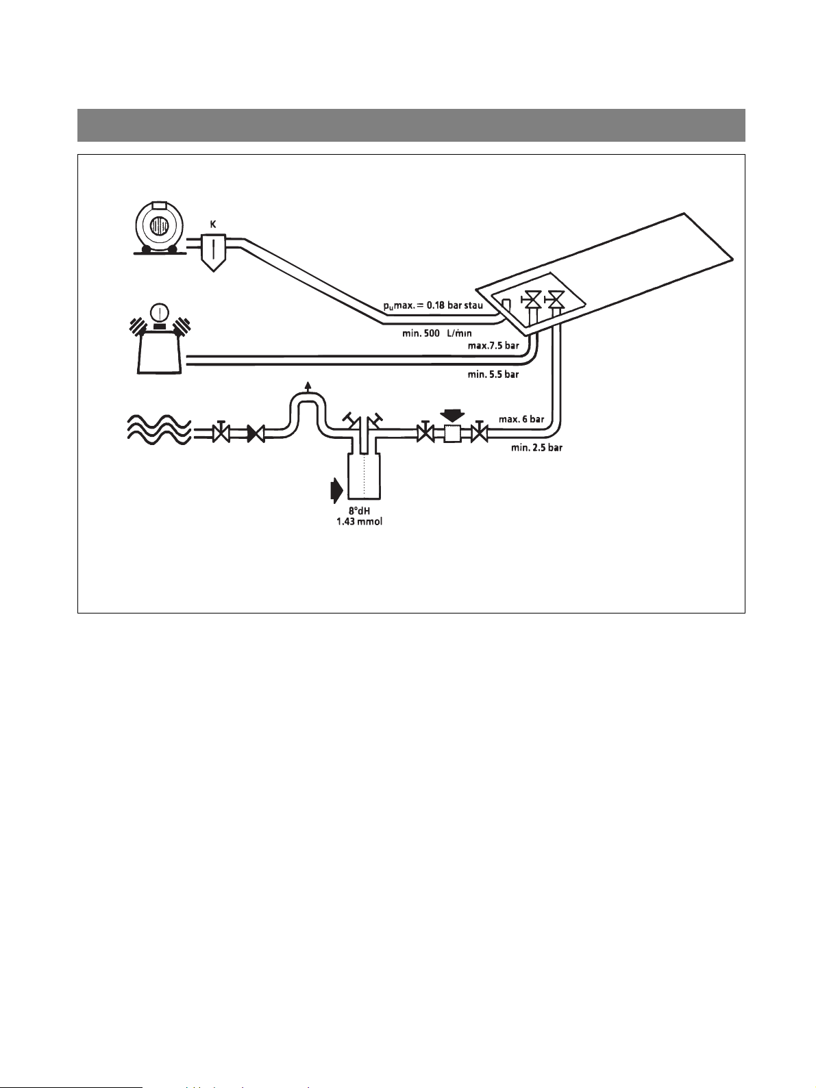
N
>80 µm
Air
Suction machine
oil-free
Cold water
Dilution hardness
(drinking water quality)
Installationsvoraussetzungen C2
,
+
, M1
+
1.2 Media quality
Water quality
Lime deposits and corrosion residues in tap water can lead
to the following malfunctions:
• Premature clogging of the filters in the unit
• Rapid clogging of the fine water paths and jets in the
treatment instruments
For these reasons, the following points must be observed:
• If the water hardness exceeds 12° dH (=2.15mmol), install a water softener.
• Set dilution hardness to 8° dH (1.43 mmol).
• Install a conventional fine filter.
Fineness: >80µm (0.08mm).
• Installation must be performed in compliance with the
recommendations of the national installation requirements (e.g. EN1717/DIN 1988).
• The water quality must comply with the national requirements for drinking water.
• The connection must be made to cold water.
Air quality
Oil-free, dry and hygienically perfect air is required for driv-
bеЦдблЬ
ing the highspeed handpiece, for cooling the burr drives
and for the cooling spray.
Suction pipe
Install steam trap K.
With a vacuum of pu >0.18 bar back pressure, the treatment center must be retrofitted with the “Vacuum limiter”
retrofit kit (Order No.: 59 68 826).
60 27 911 D3370
D3370.021.02.07.02
7
Page 8
1 Preparations Sirona Dental Systems GmbH
5
3
6
6
6
7
Center base plate
opening to floor
1
2
4
9
1
3
/8
“
min.
500mm
20"
7, 6
max.
60mm
2 3/8"
3 4 5
max.
5mm
3/16"
max.
5mm
3/16"
3/8"
12
10 x 1mm
10 x 1mm
3/8
”
x 1/32“
3/8
”
x 1/32“
1
3
/8
“
Foot end
3
6
.
5
m
m
5
0
m
m
3
6
.
5
m
m
Installationsvoraussetzungen C2
+
, M1
1.3 Supply lines in the termination panel
+
bеЦдблЬ
8 D3370.021.02.07.02
60 27 911 D3370
Page 9
Sirona Dental Systems GmbH 1 Preparations
,
Installationsvoraussetzungen C2
+
, M1
+
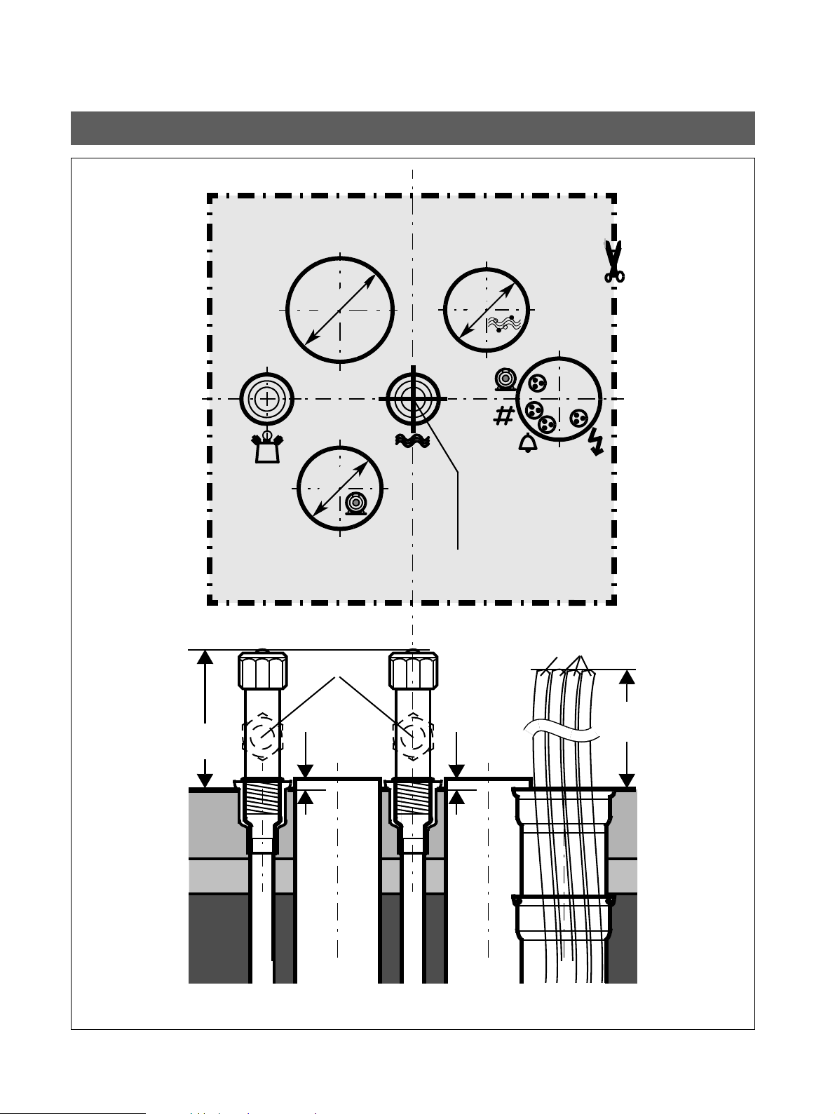
Supply lines in the termination panel
• Observe the national regulations for electrical installations (e.g. VDE 0100, VDE 0100, Part 710).
• Observe the national regulations for water supply installations (e.g. EN 1717, DIN 1988) and sewage installations (e.g. EN 12056-1).
• For the suction pipe, observe the instructions in the
Suction Machine Installation Instructions.
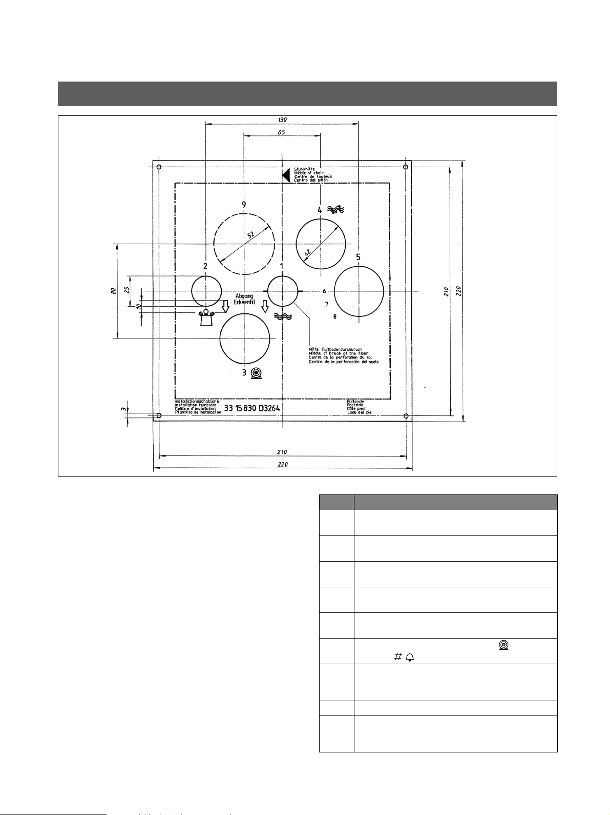
• For fastening the pipe ends in the installation field, we
recommend using an installation template. They can
be ordered from Sirona under REF 33 15 830.
If necessary, you can also prepare the template yourself based on the above sketch (not true to scale!).
Table 1: Supply lines
Item Description
1 Water inlet pipe 10x1mm,
corner valve outlet 3/8"
2 Compressed aiir inlet pipe 10x1mm, corner
valve outlet 3/8"
3 Suction pipe DN40 HT-PP DIN 19560 (polypro-
pylene, inner diameter 36.5mm!)
4 Water drain DN40 HT-PP DIN 19560 (polypro-
pylene, inner diameter 36.5mm!)
5 Installation pipe, DN40 HT-PP DIN 19560
(polypropylene, 40mm!)
6 Suction machine control cable ( )and call
cables ( ) 3x1.5mm
7 Power cable 3x1.5mm2
Fuse: 16A slow-blow
Recommended: Type B automatic circuit breaker
8 not applicable
9 Installation pipe (or corresponding flat duct) for
additional requirement e.g. practice network
connecting cable
2
bеЦдблЬ
60 27 911 D3370
D3370.021.02.07.02
9
Page 10

1 Preparations Sirona Dental Systems GmbH
ATTENTION
>500mm
<5mm
<60mm
>20“
3/8“
<3/16“
<2 3/8“
Ø 36,5 mm
10x1 mm
3/8” x 1/32”
DN 40
>5
00mm
200mm
250mm
> 20’’
8’’
10’’
Ø 36,6mm
3/8“
20
Ø 36,5 mm
Installation template
Installationsvoraussetzungen C2
+
, M1
Supply lines in the termination panel
+
Supply above the floor, "above-floor installation"
The supply pipe ends, corner valves and cables must be
routed as shown above.
The retrofit kit for above-floor installation (33 17 265) is
required for installation.
For cleaning, rinse the air and water pipes thoroughly (metal
chips!).
Supply through the floor, "underfloor installation"
1. The top edges of the corner valves for air and water
must not protrude more than 60mm above the upper
surface of the finished floor.
2. The suction and drain pipes must be flush with the upper surface of the floor (a deviation of +5mm is permissible).
Internal diameter for both pipes: 36,5mm.
3. The electrical cables must protrude at least 500 mm.
bеЦдблЬ
10 D3370.021.02.07.02
60 27 911 D3370
Page 11

Sirona Dental Systems GmbH 1 Preparations
2.
1.
A
C2+ , M1
+
L15, L37, L38, Audio
protective ground wire
SIVISION
Installationsvoraussetzungen C2
+
, M1
+
1.4 Underfloor installation of SIVISION connections
Important information for the installer
Depending on the prevailing local conditions, the existing
cable set can be installed in the cable duct of an underfloor
installation by an installer prior to the installation of the dental treatment center. In this case, please observe the following:
Proceed with extreme care when running the cables. Particularly cables L15 and L38 are very sensitive, and must
never be kinked or twisted. The cables must not overlap or
cross one another.
RS232 (L37) and the XGA cable (L38) are not yet cut to
length and terminated on the PC side. It would be impossible to pull the cables through when installing them under
floor level if a sub D connector were already connected.
These cables should always be pulled.
Free length A of cables at the treatment center end:
Length A = 600mm
If S video cable L15 is equipped with both a female and a
male connector, make sure that the female connector
(socket) points to the connection box of the treatment center.
bеЦдблЬ
2. Pull cables L15, L37 and L38 as well as the audio and
protective ground wire cables from the treatment center
through the cable duct to the location of the SIVISION
PC.
Save the accessory parts for final installation!
1. Bend the wire at the front end of cables L37 and L38 to
form a hook.
60 27 911 D3370
D3370.021.02.07.02
11
Page 12

1 Preparations Sirona Dental Systems GmbH
Chair plate
Demo plate
REF 58 71 913
REF 58 66 301
For especially uneven floor conditions,
a steel chair plate is available to compensate for the irregularities of the floor
(REF 58 71 913).
For floors which do not permit permanent connection of the unit (e.g. demo operation at a fair),
installation on a steel demo plate is possible
(REF 58 66 301).
Installationsvoraussetzungen C2
+
, M1
1.5 Mounting plates
+
bеЦдблЬ
12 D3370.021.02.07.02
60 27 911 D3370
Page 13

Sirona Dental Systems GmbH 1 Preparations
Adapter plate
If the C2+ or M1+ is installed as a replacement for an M1 at
this position, then an adapter plate, with the aid of which
the existing mounting holes can be used, is available
under the order number 58 70 493.
REF 58 70 493
Installationsvoraussetzungen C2
+
, M1
+
Mounting plates
bеЦдблЬ
60 27 911 D3370
D3370.021.02.07.02
13
Page 14

1 Preparations Sirona Dental Systems GmbH
Installationsvoraussetzungen C2
+
, M1
+
bеЦдблЬ
60 27 911 D3370
14 D3370.021.02.07.02
Page 15

2 Dimensions, technical data
C2+, M1
2.1 Dimensions of the C2+ 1:20 ................................................................................................... 16
+
bеЦдблЬ
2.2 Dimensions of the M1
2.3 Technical data ....................................................................................................................... 22
60 27 911 D3370
D3370.021.02.07.02
+
1:20 .................................................................................................. 19
15
Page 16

2 Dimensions, technical data Sirona Dental Systems GmbH
1700
67”
1300
51 3/16”
2500
98 7/16”
* 160 - 500
6 1/4" - 19 5/8”
Recommended distances from cabinet or wall.
Hazard warning:
The lamp and the Tray installed here
have a swivel range which exceeds
the specified distances!
Center floor opening
* Depending on the setting of the support arm stop (factory setting: 500mm)
Installationsvoraussetzungen C2
+
, M1
2.1 Dimensions of the C2+ 1:20
+
60 27 911 D3370
16 D3370.021.02.07.02
Page 17

Sirona Dental Systems GmbH 2 Dimensions, technical data
Standard upholstery
* max.: backrest and chair in highest position
min.: backrest and chair in lowest position
45
1 3/4”
1212
47 3/4”
* max. 760 30”
min. 400 15 3/4”
max. 950 37 3/8”
min. 805 31 5/8”
270
10 3/4”
max. 840 33”
min. 760 30”
65°
10°
1950
76 3/4”
1875
73 3/4”
45°
Height of lamp with
SIVISION on swivel
arm or lamp support
tube
Height of lamp without
SIVISION or with
SIVISION on tray
SIROLUXLEDview
Installationsvoraussetzungen C2
+
, M1
+
Dimensions of the C2+ 1:20
bеЦдблЬ
60 27 911 D3370
D3370.021.02.07.02
17
Page 18

45
1 3/4”
max. 380 +15
15“ +
5/8”
2070 +50***
81 1/2” +
2“ ***
max. 850 - 1100**
33 1/2" - 43 1/4”
950
37 3/8”
max. 1010 - 1220**
39 3/4" - 48”
190
7 1/2”
459
18”
430 +15
17“ +5/8”
180
7”
90°
90°
90°
60°
750
29 1/2”
770
30 3/8”
250
9 7/8”
** Depending on the height adjustment of the support arm
*** Depend ing on the chair height
2 Dimensions, technical data Sirona Dental Systems GmbH
Installationsvoraussetzungen C2
+
, M1
Dimensions of the C2+ 1:20
+
18 D3370.021.02.07.02
60 27 911 D3370
Page 19

Sirona Dental Systems GmbH 2 Dimensions, technical data
250
9 7/8”
1450
57”
2500
98 7/16”
300
11 3/4”
* 1150
45 1/4”
**1250
49 1/4“
* Support arm short
** Support arm long
Center floor opening
Recommended distances from cabinet or wall.
Hazard warning:
The lamp and the Tray installed here
have a swivel range which exceeds
the specified distances!
Installationsvoraussetzungen C2
+
, M1
+
2.2 Dimensions of the M1+ 1:20
bеЦдблЬ
60 27 911 D3370
D3370.021.02.07.02
19
Page 20

2 Dimensions, technical data Sirona Dental Systems GmbH
1212
47 3/4”
* max. 760 30” *
min. 400 15 3/4”
max. 965 38”
min. 815 32”
max. 1050 41 3/8”
min. 900 35 1/2”
45
1 3/4”
Standard upholstery
* max.: backrest and chair in highest position
min.: backrest and chair in lowest position
270
10 3/4”
45°
65°
10°
1950
76 3/4”
1875
73 3/4”
Height of lamp with
SIVISION on swivel
arm or lamp support
tube
Height of lamp without
SIVISION or with
SIVISION on tray
SIROLUXLEDview
Installationsvoraussetzungen C2
+
, M1
Dimensions of the M1+ 1:20 t
+
20 D3370.021.02.07.02
60 27 911 D3370
Page 21

Sirona Dental Systems GmbH 2 Dimensions, technical data
2070 +50**
81 1/2“ +2“ **
max. 1240 ****
48 7/8“
950
37 3/8”
1030
40 1/2"
120°
180°
45
1 3/4”
190
7 1/2”
max. 1060 ***
41 3/4”
459
18”
max. 380 +15
15“ +5/8”
430 +15
17“ +5/8”
180
7”
90°
90°
90°
60°
750
29 1/2”
770
30 3/8”
250
9 7/8”
*** Support arm short
**** Support arm long
** Depending on the chair height
Installationsvoraussetzungen C2
+
, M1
+
Dimensions of the M1+ 1:20
bеЦдблЬ
60 27 911 D3370
D3370.021.02.07.02
21
Page 22

2 Dimensions, technical data Sirona Dental Systems GmbH
0123
Installationsvoraussetzungen C2
+
, M1
2.3 Technical data
+
C2
+
, M1
+
Weight C2+ M1
incl. / without packaging
Dentist element, assistant element, water unit
Chair
Upholstery
Dimensions of the packaging C2+ / M1
Dentist element, assistant element, water unit
Chair
Upholstery
90,5kg / 50,5kg 85,5kg / 64,5kg
142kg / 112kg 142kg / 112kg
13kg / 10kg 13kg / 10kg
+
122cm x 63cm x 137cm
153cm x 65cm x 83 cm
120cm x 52cm x 40 cm
Power supply connection / Nominal current
at 230V, 50Hz 4,5A
at 115V, 50/60Hz 9,5A
at 100V, 50/60Hz 11,5A
On-site pressure readings
Air min./max.
Water min./max.
5.5 / 7.5bar
2.5 / 6bar
Operating conditions
Ambient temperature: 10°C – 40°C (50°F – 104°F)
Relative humidity: 30% – 75%
Air pressure: 700hPa – 1060hPa
Transport and storage conditions
Temperature: -40°C – +70°C (-40°F – 158°F)
Relative humidity: 10% – 95%
Air pressure: 500hPa – 1060 hPa
Protection class
Class I equipment
Degree of protection against ingress of water
Ordinary equipment (not protected). The foot switch
is protected against dripping water IPX 1.
Mode of operation:
Continuous operation with intermittent loading corresponding to the dental mode of working.
Tests / approvals
This dental treatment center complies with the
requirements of
IEC 60601-1 (electrical and mechanical safety)
and of
IEC 60601-1-2(electromagnetic compatibility).
DVGW: This unit complies with the technical rules
and requirements on safety and hygiene for connection to the drinking water supply, provided that a
disinfection system is installed.
This product bears the CE marking in accordance
with the provisions of the Council Directive 93/42/
EEC of June 14, 1993 concerning medical devices.
+
60 27 911 D3370
22 D3370.021.02.07.02
Page 23

3 Electromagnetic compatibility
NOTE
i
C2+, M1+
3.1 Accessories ........................................................................................................................... 24
3.2 Electromagnetic emission ...................................................................................................... 25
3.3 Immunity to interference ........................................................................................................ 26
3.4 Working clearances ............................................................................................................... 28
bеЦдблЬ
The C2+, M1+ fulfills all requirements for electromagnetic compatibility (EMC) compliant with IEC 60601-1-2.
+
The C2
Observance of the following information is necessary to ensure safe operation regarding EMC aspects.
60 27 911 D3370
D3370.021.02.07.02
, M1+ is referred to as "UNIT" in the following.
23
Page 24

3 Electromagnetic compatibility Sirona Dental Systems GmbH
Installationsvoraussetzungen C2
+
, M1
3.1 Accessories
Making the PC connection
+
Designation of interface cables
Supplier
for the PCs
XGA cable, 10m (L38) Sirona
S video cable, 10m (L15) Sirona
RS232 cable, 10m (L37) Sirona
Audio cable, 10m Sirona
FireWire, 10m
(for the CEREC-PC
2nd protective ground wire, 1.5mm
•The UNIT may be operated only with accessories and
spare parts approved by Sirona. Unapproved accessories and spare parts may lead to an increased emission
of or a reduced immunity to interference.
•The UNIT should not be operated immediately adjacent
to other devices. If this proves to be unavoidable, the
UNIT should be monitored to check and make sure that
it is used properly.
The EMC measurements were performed with the following
PCs:
2
Sirona
, 10m Sirona
bеЦдблЬ
PC as peripheral device for
checking the interfaces
with:
Extension of the PCs
Graphics card PC 1: Graphik - Controller
Frame grabber card PicPort Color frame grabber
PC 1: Siemens Fujitsu,
Pentium III, 650 MHz
Matrox Millenium G450
DualHead
PC 2: Graphik controller
MS I NX 6800GT
card (Leutron)
REF: 46 93 961
60 27 911 D3370
24 D3370.021.02.07.02
Page 25

Sirona Dental Systems GmbH 3 Electromagnetic compatibility
Installationsvoraussetzungen C2
+
, M1
+
3.2 Electromagnetic emission
The UNIT is intended for operation in the electromagnetic
environment specified below.
Emission measurement Conformity Electromagnetic environment guidelines
HF emission according to CISPR 11 Group 1
HF emission according to CISPR 11 Class B The UNIT is intended for use in all facilities, including residen-
Harmonics
according to IEC 61000-3-2
Voltage fluctuations / Flicker according
to IEC 61000-3-3
a. If an HF electrosurgical unit is integrated, it must emit electromagnetic energy in order to function properly. Any electrical
devices located nearby may be influenced whenever the HF surgical unit is active. According to IEC 60601-2-2, Chap. 36, no
limit values have been defined for active HF surgical units. They are therefore classified as Group 1 devices according to
CISPR 11.
Class A
compliant
a
The customer or user of the UNIT should make sure that it
is used in such an environment.
The UNIT uses HF energy only for its internal function. The
HF emission is therefore very low, and it is improbable that
nearby electronic devices might be disturbed.
tial areas and in any facilities connected directly to a public
power supply providing electricity to buildings used for residential purposes.
bеЦдблЬ
60 27 911 D3370
D3370.021.02.07.02
25
Page 26

3 Electromagnetic compatibility Sirona Dental Systems GmbH
Installationsvoraussetzungen C2
+
, M1
3.3 Immunity to interference
+
The UNIT is intended for operation in the electromagnetic
environment specified below.
Immunity interfer-
IEC 60601-1-2 test level Conformance level Electromagnetic environment
ence tests
Electrostatic dis-
± 6kV contact discharge
± 6kV contact discharge
charge (ESD) according to IEC 61000-4-2
Electrical fast transient/burst
according to IEC
61000-4-4
Surge voltages
according to IEC
61000-4-5
Voltage dips, short
interruptions and variations of the power
supply
according to IEC
61000-4-11
± 8 kV air discharge
± 1kV for input and output
lines
± 2kV power cables
± 1kV push-pull voltage
± 2kV push-pull voltage
<5% U
dip of U
40% U
dip of U
for ½ period (>95%
T
)
T
for 5 periods (60%
T
)
T
70% UT for 25 periods (30%
dip of U
<5% U
of U
)
T
for 5sec. (>95% dip
T
)
T
± 8kV air discharge
± 1kV for input and output
lines
± 2kV power cables
± 1kV push-pull voltage
± 2kV push-pull voltage
<5% UT for ½ period
(>95% dip of U
40% U
dip of U
70% UT for 25 periods
(30% dip of U
<5% U
(>95% dip of U
The customer or user of the UNIT should make sure that it
is used in such an environment.
guidelines
Floors should be made of wood or
concrete or covered with ceramic tiling. If the floor surface consists of
synethetic material, the relative
humidity must be at least 30%.
The quality of the supply voltage
should conform to the typical business or hospital environment.
The quality of the supply voltage
should conform to the typical business or hospital environment.
The quality of the supply voltage
)
T
for 5 periods (60%
T
)
T
)
T
for 5sec.
T
)
T
should correspond to the typical business or hospital environment.
If the user of the UNIT requires it to
continue functioning following interruptions of the power supply, it is recommended to have the UNIT
powered by an uninterruptible power
supply or a battery.
bеЦдблЬ
Magnetic field of
power frequencies
(50/60 Hz)
according to IEC
61000-4-8
Remarks: U
is the AC supply voltage prior to application of the test level.
T
3 A/m 3 A/m The power frequency magnetic fields
should correspond to the typical values found in the relevant business
and hospital environment.
60 27 911 D3370
26 D3370.021.02.07.02
Page 27

Sirona Dental Systems GmbH 3 Electromagnetic compatibility
d 12,[]P=
d 12,[]P=
at 80MHz to 800MHz
d 23,[]P=
at 800MHz to 2.5GHz
Installationsvoraussetzungen C2
+
, M1
+
Immunity interference tests
Conducted HF interference
IEC 61000-4-6
Radiated HF interference
IEC 61000-4-3
IEC 60601-1-2 test level Conformance level Electromagnetic environment
guidelines
Portable and mobile radio equipment
must not be used within the recommended working clearance from the
UNIT and its cables, which is calculated based on the equation suitable
for the relevant transmission frequency.
Recommended working clearance:
3V
eff
150 kHz to 80 MHz
3V/m
80MHz to 800MHz
3V/m
800MHz to 2.5GHz
a
a
a
3V
3V
3V
eff
eff
eff
where P is the nominal transmitter
output in watts (W) specified by the
transmitter manufacturer and d is the
recommended working clearance in
meters (m).
The field strength of stationary radio
transmitters is based on a local investigation for all frequenciesb less than
the conformance level for all frequen-
c
cies
.
Interference is possible in the vicinity
of equipment bearing the following
graphic symbol.
bеЦдблЬ
a. The higher frequency range applies at 80 MHz and 800MHz.
b. The field strength of stationary transmitters such as the base stations of radio telephones and land mobile services,
amateur radio stations as well as AM and FM radio and television broadcasting stations cannot be accurately predetermined. An investigation of the location is recommended to determine the electromagnetic environment resulting from
stationary HF transmitters. If the field strength measured at the UNIT location exceeds the conformance level specified
above, the UNIT must be observed with respect to its normal operation at each application site. If unusual performance
characteristics are observed, it may be necessary to take additional measures such as reorientation or repositioning of
the UNIT.
c. A frequency range of 150kHz to 80MHz results in a field strength of less than 3 V/m.
60 27 911 D3370
D3370.021.02.07.02
27
Page 28

3 Electromagnetic compatibility Sirona Dental Systems GmbH
d 12,[]P=
d 12,[]P=
d 23,[]P=
Installationsvoraussetzungen C2
+
, M1
3.4 Working clearances
Recommended working clearances between portable and mobile HF communication devices and
the UNIT
The UNIT is intended for operation in an electromagnetic
environment, where radiated HF interference is checked.
The customer or the user of the
electromagnetic interference by duly observing the minimum distances between portable and/or mobile HF communication devices (transmitters) and the
values may vary according to the output power of the relevant communication device as specified above.
UNIT can help prevent
UNIT. These
+
Nominal transmitter output
[W]
150kHz to 80MHz 80MHz to 800MHz 800MHz to 2.5GHz
0,01 0,12 0,12 0,23
0,1 0,38 0,38 0,73
11,21,22,3
10 3,8 3,8 7,3
100 12 12 23
For transmitters whose maximum nominal output is not
specified in the above table, the recommended working
clearance d in meters (m) can be determined using the
equation in the corresponding column, where P is the maximum nominal output of the transmitter in watts (W) specified by the transmitter manufacturer.
Annotation 1
The higher frequency range applies at 80 MHz and 800
MHz.
Annotation 2
These guidelines may not be applicable in all cases. The
propagation of electromagnetic waves is influenced by
their absorption and reflection by buildings, objects and
persons.
Working clearance according to transmission frequency [m]
bеЦдблЬ
60 27 911 D3370
28 D3370.021.02.07.02
Page 29

Page 30

tЙ=кЙлЙкоЙ=нЬЙ=кбЦЬн=нз=г~вЙ=~еу=~днЙк~нбзел=пЬбЕЬ=г~у=ДЙ=кЙимбкЙЗ=ЗмЙ=нз=нЙЕЬебЕ~д=бгйкзоЙгЙенлK
«=pбкзе~=aЙен~д=pулнЙгл=dгДe=OMMNJOMMQ pйк~ЕЬЙW=ЙеЦдблЕЬ= mкбенЙЗ=бе=dЙкг~еу
aPPTMKMONKMOKMTKMO===MVKOMMV ûKJkêKW=NNN=UTP fгйкбг¨=Йе=^ддЙг~ЦеЙ
pбкзе~=aЙен~д=pулнЙгл=dгДe
áå=íÜÉ=rp^W
c~Дкбвлнк~≈Й=PN
SQSOR=_ЙелЬЙбг
dЙкг~еу
пппKлбкзе~KЕзг
pбкзе~=aЙен~д=pулнЙгл=ii`
QUPR=pбкзе~=aкбоЙI=pмбнЙ=NMM
`Ь~кдзннЙI=k`=OUOTP
rp^
lêÇÉê=kç
SM=OT=VNN=aPPTM
 Loading...