

Page 1
H
`N
mСдЙЦЙ=меЗ=oЙбебЦмеЦ=ЗмкЕЬ=З~л=mк~сблнЙ~г
`~кЙ=~еЗ=`дЙ~ебеЦ=Ду=нЬЙ=mк~ЕнбЕЙ=qЙ~г
bенкЙнбЙе=Йн=еЙннзу~ЦЙ=й~к=дЫ¨имбйЙ=Зм=Е~ДбеЙн
`мбЗ~Зз=у=дбгйбЙт~=йзк=й~кнЙ=ЗЙд=йЙклзе~д=ЗЙ=д~=Езелмдн~
aЙмнлЕЬ=L=bеЦдблЬ=L=cк~е´~бл=L=bлй~¥зд
Page 2

Page 3

Sirona Dental Systems GmbH
mСдЙЦЙ=меЗ=oЙбебЦмеЦ=ЗмкЕЬ=З~л=mк~сблнЙ~г
`~кЙ=~еЗ=`дЙ~ебеЦ=Ду=нЬЙ=mк~ЕнбЕЙ=qЙ~г
aЙмнлЕЬbеЦдблЬcê~å´~áëbëé~¥çä
bенкЙнбЙе=Йн=еЙннзу~ЦЙ=й~к=дЫ¨имбйЙ=Зм=Е~ДбеЙн
`мбЗ~Зз=у=дбгйбЙт~=йзк=й~кнЙ=ЗЙд=йЙклзе~д=ЗЙ=д~=Езелмдн~
59 06 511 D 3386
D 3386.103.01.06.09
Page 4

Page 5
H
`N
mСдЙЦЙ=меЗ=oЙбебЦмеЦ=ЗмкЕЬ=З~л=mк~сблнЙ~г
aЙмнлЕЬ
Page 6

Sirona Dental Systems GmbH
Pflege und Reinigung durch das Praxisteam Sehr geehrter Anwender,
zur Werterhaltung und sicheren Funktion Ihres Behandlungsplatzes ist es erforderlich, diesen regelmäßig zu
pflegen, zu reinigen und zu desinfizieren.
Die von Ihnen durchzuführenden Arbeitsschritte sind in
diesem Dokument beschrieben.
Wartung der Behandlungseinheit durch den
Servicetechniker
Trotz hervorragender Qualität Ihres Behandlungsplatzes und regelmäßiger Pflege durch das Praxisteam ist
es im Interesse der Betrie bssicherhe it erforderlich , dass
in festgelegten Zeit abständen Ins pektionen un d Wartungen durch den Servicetechniker durchgeführt werden.
Einzelheiten hierzu entnehmen Sie bitte Ihrer
Gebrauchsanweisung.
+
-Team
Ihr C1
59 06 511 D 3386
2 D 3386.103.01.06.01
Page 7

Sirona Dental Systems GmbH Inhaltsverzeichnis
Inhaltsverzeichnis
1 Anschlusskasten....................................................................................................................... 6
2 Speischale.................................................................................................................................. 7
3 Sauganlage ................................................................................................................................ 8
3.1 Pflege................................................................................................................ 8
3.2 Desinfektion bei Trockenabsaugung................................................................ 8
3.3 Desinfektion bei Nassabsaugung................................................................... 10
3.4 Saughandstücke............................................................................................. 11
3.5 Saugschläuche reinigen ................................................................................. 12
3.6 Saugschläuche thermodesinfizieren............................................................... 13
4 Amalgam – Abscheidung........................................................................................................ 14
5 Instrumentenschläuche.......................................................................................................... 15
5.1 Instrumentenschläuche abnehmen, austauschen.......................................... 15
5.2 Turbinenschlauch,.......................................................................................... 15
6 Desinfektionsanlage................................................................................................................ 16
6.1 Mikrobiologische Kontrolle des Wassers........................................................ 16
6.2 Sanierung....................................................................................................... 17
6.3 Sanier-Vorgang unterbrechen........................................................................ 22
7 Oberfläch en / O - R in g e ............. .. .............. .. ............. .. .............. .. ............. .. .............. ............. ..... 23
aЙмнлЕЬ
8 POLYLUX - Kaltlicht Handstück............................................................................................. 25
8.1 Pflege und Reinigung der Griffhülse............................................................... 25
8.2 Pflege und Reinigung des Lichtleiters............................................................ 25
9 Videokamera SIROCAM 3 / SIROCAM C und Monitor......................... ................................. 26
9.1 Pflege und Reinigung der SIROCAM 3 .......................................................... 26
9.2 Pflege und Reinigung der SIROCAM C.......................................................... 27
9.3 Pflege und Reinigung des Monitors................................................................ 27
10 Sicherheitsschalter überprüfen................................................. ............................................ 28
59 06 511 D 3386
D 3386.103.01.06.01
3
Page 8

Inhaltsverzeichnis Sirona Dental Systems GmbH
59 06 511 D 3386
4 D 3386.103.01.06.01
Page 9
Sirona Dental Systems GmbH
08:00
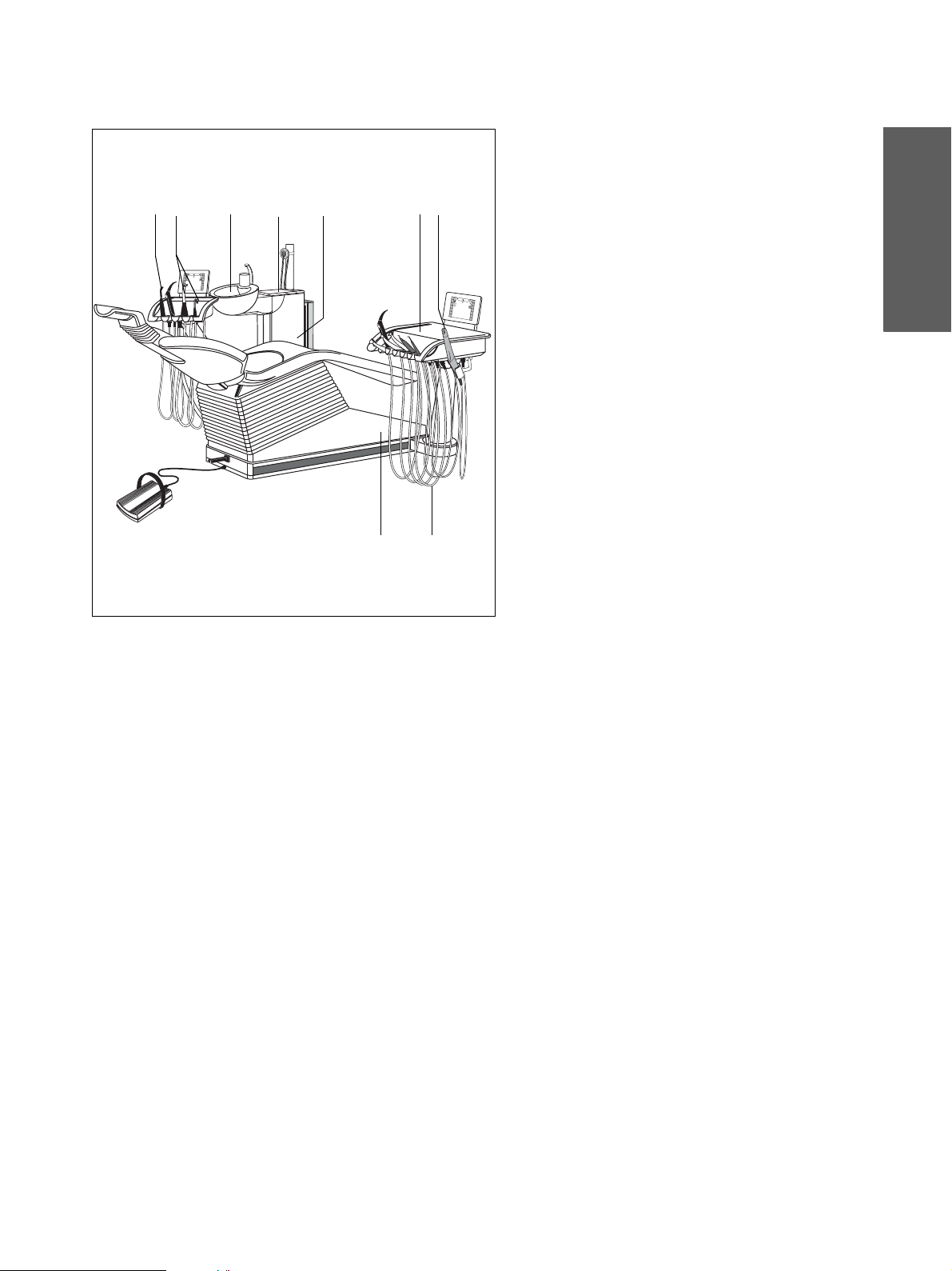
Übersicht
Die in der Übersicht angegebenen Ziffern entspre-
83
2
08:00
47
6
1
9
0
8
:
0
0
5
chen der Kapitelnummerierung im Inhaltsverzeichnis.
Somit können Sie die durchzuführenden Arbeiten
schnell in diesem Dokument finden.
1 Anschlusskasten
2Speischale
3 Sauganlage
4 Amalgam – Abscheidung
5 Instrumentenschläuche
6 Desinfektionsanlage
7 Oberflächen
aЙмнлЕЬ
8 POLYLUX Kaltlicht-Handstück
9 Videokamera SIROCAM 3 / SIROCAM C
Monitor
10 Sicherheitsschalter überprüfen
Die Pflege der nachfol gend genannten Produkte entneh men Sie bitte der jeweils mitgelieferten Gebrauchsanweisung.
•Spritze SPRAYVIT,
• Hand- und Winkelst ück e T1 CLASSIC, T1 LINE bzw .
T1 TITAN,
• Elektromotoren,
• Turbinen,
• Zahnsteinentferner SIROSONIC L,
• Elektrochirurgiegerät SIR O T OM,
• Videokamera SIROCAM 3,
• Geräteleuchte SIR OLUX FANTASTIC
59 06 511 D 3386
D 3386.103.01.06.01
5
Page 10
1 Anschlusskasten Sirona Dental Systems GmbH
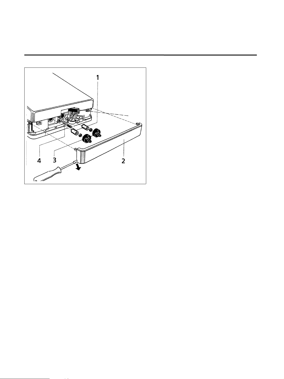
1 Anschlusskasten
Sollten Sie Veränderungen der Mediendurchflüsse feststellen, kontrollieren Sie bitte die Filter für Wasser und
Luft (1) auf Durchlässigkeit. Wenn nötig wechseln Sie
diese aus.
Filter (1) für Wasser und Luft auswechseln.
Dazu vorher den Hauptschalter AUS-schalten. Die Ver-
kleidung (2) abhebeln (Schraubendreher).
AUS
Schraubkappen (3) entfernen und Filter auswechseln.
Filter
Bestell - Nr. 14 43 436
Die Hauptsicherung (4) befindet sich unterhalb des
Luftfilters.
Geräte-Hauptsicherung für 230V
~:
T 6,3AH, 250V
Geräte-Hauptsicherung für 100V
T 10AH, 250V~, Bestell-Nr. 10 77 460
~, Bestell-Nr. 10 77 452
~ / 115V~:
59 06 511 D 3386
6 D 3386.103.01.06.01
Page 11
Sirona Dental Systems GmbH 2 Speischale
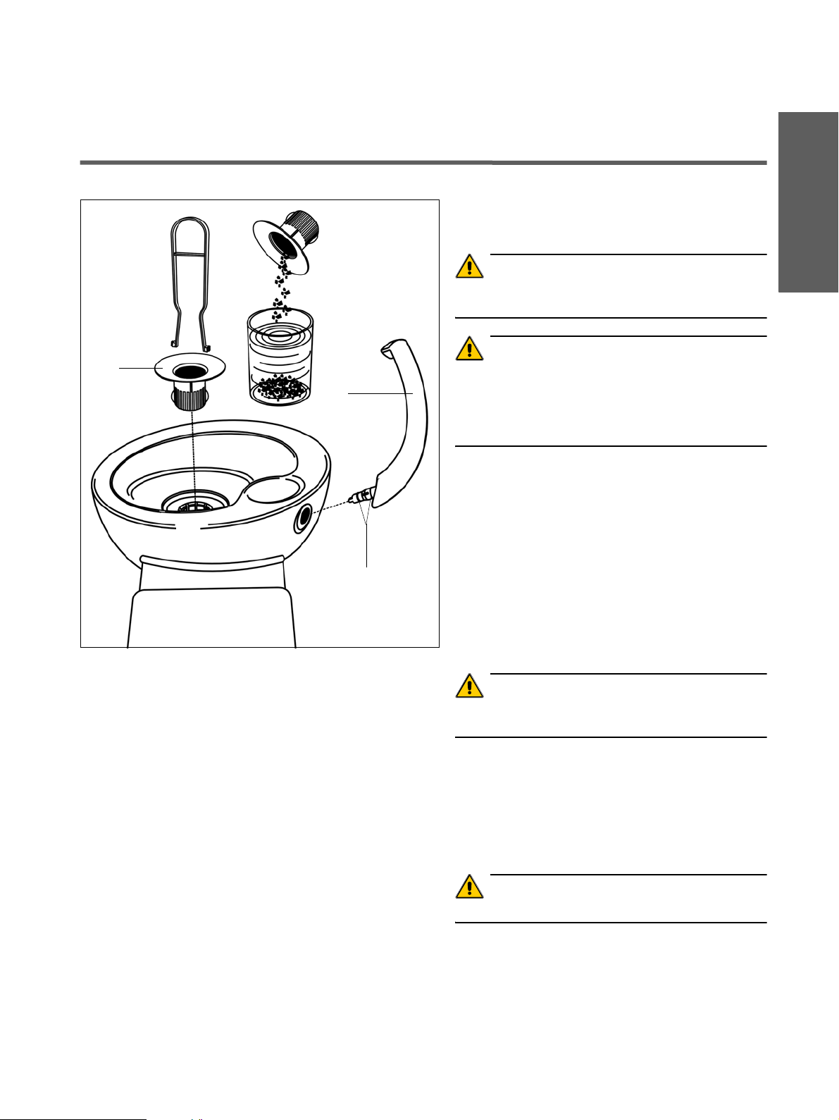
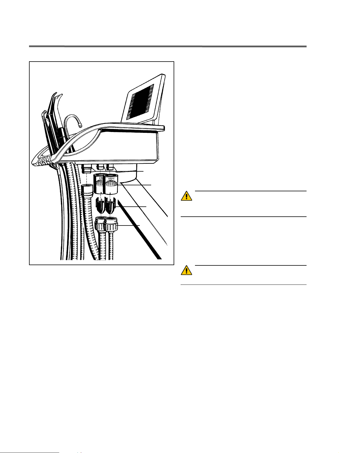
2 Speischale
Nach jedem Patienten
Speischale reinigen.
aЙмнлЕЬ
ACHTUNG
Amalgam
5
6
Fett
V erw ende n Sie n ur d ie v on Sirona zugel asse nen Rei nigungsmittel !
ACHTUNG
Keine ha ushal tsüb lic hen R eini gungs- un d Pfleg emitte l
verwenden . Schäu mende haus haltsü b liche Rein igung smittel führen zum An saugen vo n Schaum und W asser in
das trock ene Absaugsyst em und können zu Sc häden an
der Saugmaschine fü hren.
Täglich vor der Mittagspause und nach
Praxisende
Goldfänger (5) herausnehmen und reinigen.
Amalgamreste in einem geschlo ss enen Behälter mit
Wasser sammeln und bei Austausch des Amalgamrotors (siehe Seite 1 4) durch Einf üllen in de n Rotor mit entsorgen.
Nach dem Reinigungsvorgang muss zum Nachspülen
mindestens 1 Liter Wasser in die Speischale ein gefüllt
werden.
59 06 511 D 3386
D 3386.103.01.06.01
ACHTUNG
Amalgamreste im Goldfänger nic ht in die Speisch ale
oder in das Wasc hbec ken entsorgen!
Wöchentlich
Mundglasauslauf (6) oder ggf. Hydrokolloidadapter herausziehen und reinigen.
Vor dem Einstecken des Mundgl asausla ufes bzw. des
Hydrokolloidadapters die O-Ringe leicht fetten.
ACHTUNG
V erw ende n Sie nur die v on Si rona z ugelas senen Fette !
7
Page 12
3 Sauganlage Sirona Dental Systems GmbH
3.1 Pflege
3 Sauganlage
3.1 Pflege
Nach jedem Patienten
Um die stete Einsatz bereits chaft der Absauganlage zu
gewährleis ten, muss nach jedem Patienten, vor allem
nach jedem blutigen Eingriff und nach Gebrauch von
Wasserstoffperoxid (H
schläuche ein großes Glas kaltes, klares Wasser abgesaugt werden .
Bei Langzeitbehandlungen muss mindestens alle
60 min. ein Glas Wasser abgesaugt werden.
3.2 Desinfektion bei Trockenabsaugung
), über die benutzten Saug-
2O2
Täglich vor der Mittagspa use und nach
Praxisende
Die Sauganlage wird täglic h mit ke imhal tigen Sek reten,
Speichel und Blut be las tet. Aus hygienischen G rü nden
ist deshalb d ie Desinf ektion m it einem von Sirona freigegebenem Reinigungs- und Desinfektionsmittel unbedingt erforderlich.
ACHTUNG
V erw end en Sie nur d ie v on Si rona z ugelas senen R einigungs- und Desin f ek tionsmi tte l !
Keine Waschmittel oder andere Desinfektionsmittel
benutzen!
• Reinigungslösung in einem separ atem Gefä ß nach
Herstellerangab en ansetze n und gut durchmischen.
• Goldfänger herau snehmen .
• Speischale reinigen.
8
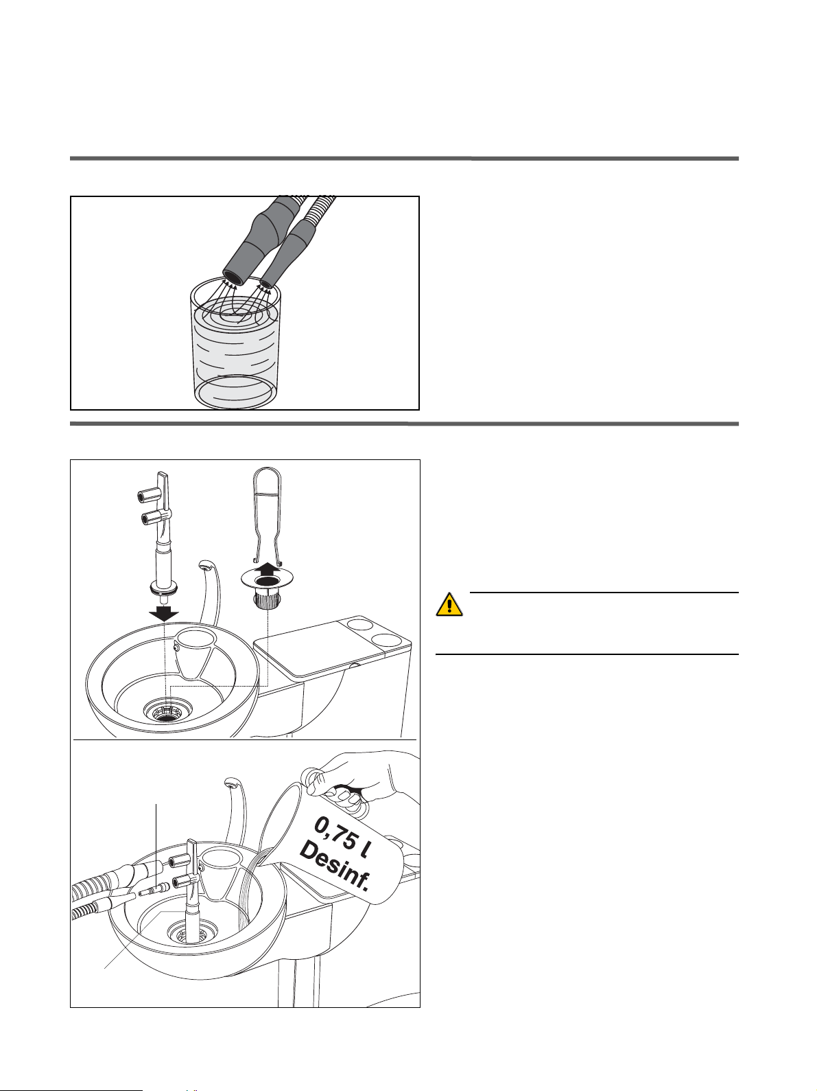
• Reinigungsadapter bis zum Ansch lag einstec k en. Für
den Speichelsauge r-Schlau ch m uss das Zwisch enstück (8) in d en Rein igungs adapt er ges tec kt w erd en.
• Reinigungslösung
schale einfüllen (ca.
• Saugschläuche aus ihren Köchern entn ehmen und
möglichst gleichz eitig sei tlich am Reinig ungsada pter
aufstecken.
• Die Reinigungslö sung wi rd a bgesa ugt.
Der Reinigungsv organg daue rt einige Min uten.
bis zur Füllgrenze A in die Spei-
0,75 Liter).
A
59 06 511 D 3386
8 D 3386.103.01.06.01
Page 13
Sirona Dental Systems GmbH 3 Sauganlage
3.2 Desinfektion bei Trockenabsaugung
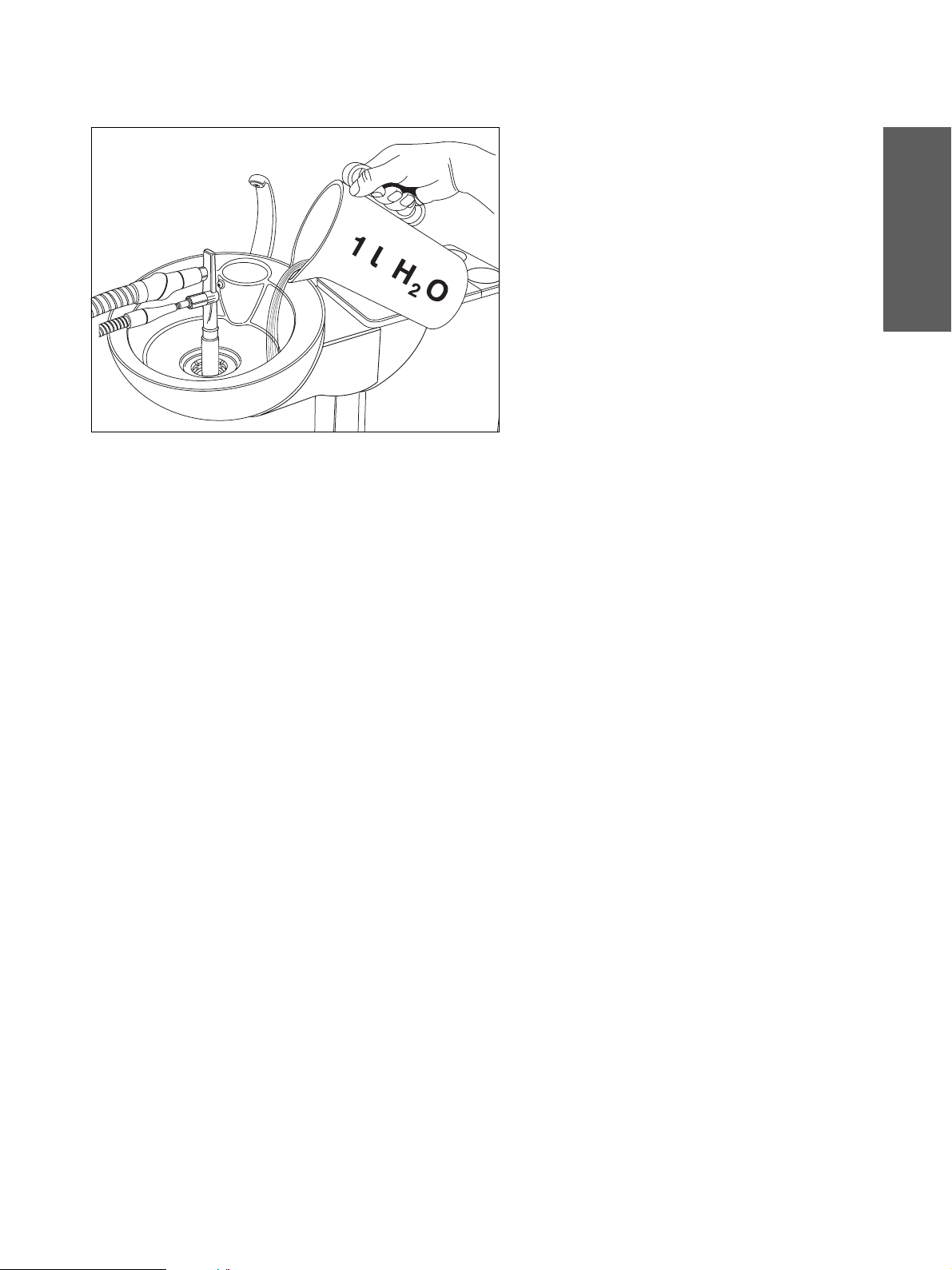
• Nach dem Reini gungs vo rgan g m uss min desten s 1 L iter Wass er in die Spei schale ein gefüllt und a bgesaugt
werden, damit di e Saug schlä uche k eine Rü c kstän de
des Desinf ektio nsmi ttels aufw ei sen.
• Nach Beendigung des Sau gvorga nges die Schläu che
abziehen und in Ih ren Köchern ab lege n.
• Reinigungsadapte r entne hmen.
• Danach Goldfäng er wi eder ei nsetz en .
aЙмнлЕЬ
59 06 511 D 3386
D 3386.103.01.06.01
9
Page 14
3 Sauganlage Sirona Dental Systems GmbH
3.3 Desinfektion bei Nassabsaugung
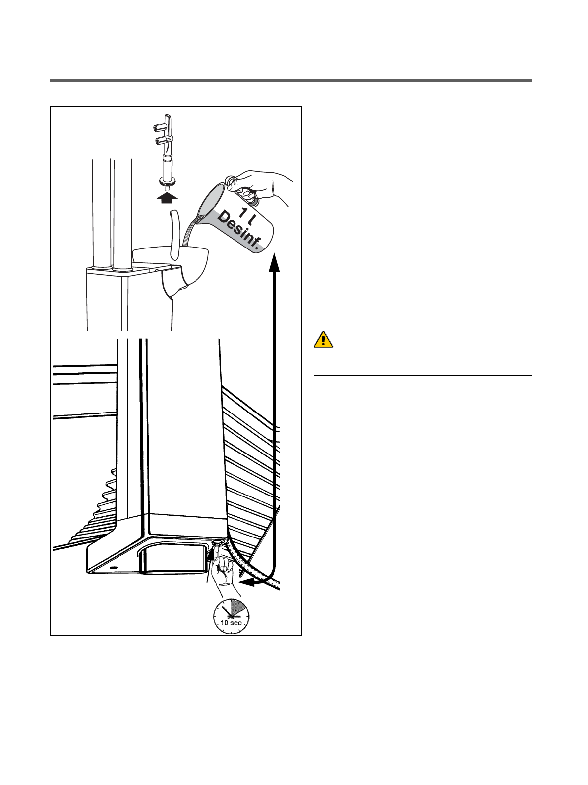
3.3 Desinfektion bei Nassabsaugung
Separierautomatik und ggf. Amalgamabscheider sind
hierbei nicht in der Wassereinheit eingebaut. Separation und Amalgamabscheidung erfolgen zentral.
Täglich vor der Mittagspause und
nach Praxisende
• Die Sauganlage wie un ter 3.2 D esinfektio n bei
Trockenabsaugung beschrieben, mit ein em geeigne -
ten Reinigungs- und Desinfektionsmit tel durchs pülen .
• Ist die Flüssigk ei t über die be iden Sa ugsch läuch e a bgesaugt, den Reinigungsa dapter entnehm en.
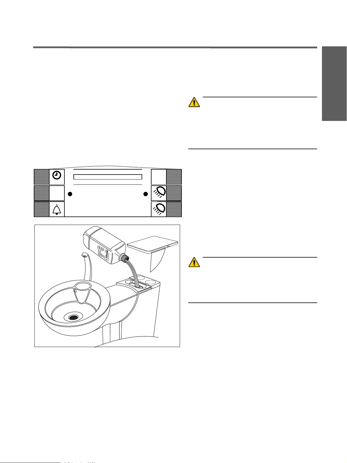
• Anschließend eine n Liter Des inf ek tionsl ösung in die
Speischale gießen und dabei ca. 10 Sekunden lang
die Taste (Pfeil) drück en.
Durch den Tastendruck gelangt die Reinig ungs- und
Desinfekt ionsflüs sigkei t von der Spei schale aus über
das Speischalen v entil in di e Vakuumleitung.
gleichzeitig
• Danach Goldfänger wied er eins etz en.
ACHTUNG
V erw end en Sie nur d ie v on Si rona z ugelas senen R einigungs- und Desin f ek tionsmi tte l !
Keine Waschmittel oder andere Desinfektionsmittel
benutzen!
59 06 511 D 3386
10 D 3386.103.01.06.01
Page 15

Sirona Dental Systems GmbH 3 Sauganlage
3.4 Saughandstücke
3.4 Saughandstücke
Sterilisation
Die Saugkanüle (1),
5
das Zwischenstück (2),
das Saughandstück (3),
aЙмнлЕЬ
das Handstück (4) des Speichelsaugers
2
3
t
t
e
F
1
4
3
F
e
t
t
und die chirurgische Absaugkanüle (5)
sind sterilisierbar.
Sterilisation nur im Autoklaven bei 135 °C, 2,1 bar.
Thermodesinfektion
Alle Teile können bei 93 °C thermodesinfiziert werden.
Desinfektion
Alle Teile können m it Desinfektionslösun g besprüht oder
abgewischt werden.
ACHTUNG
V erw ende n Sie n ur d ie v on Sirona zugel asse nen Rei nigungsmittel!
O-Ringe danach an den Trennstellen fetten!
Wöchentlich
Saughandstück am Gelenk tr ennen, reini gen und Tr ennstellen fetten.
ACHTUNG
V erw ende n Sie nur die v on Si rona z ugelas senen Fette !
59 06 511 D 3386
D 3386.103.01.06.01
11
Page 16
3 Sauganlage Sirona Dental Systems GmbH
3.5 Saugschläuche reinigen
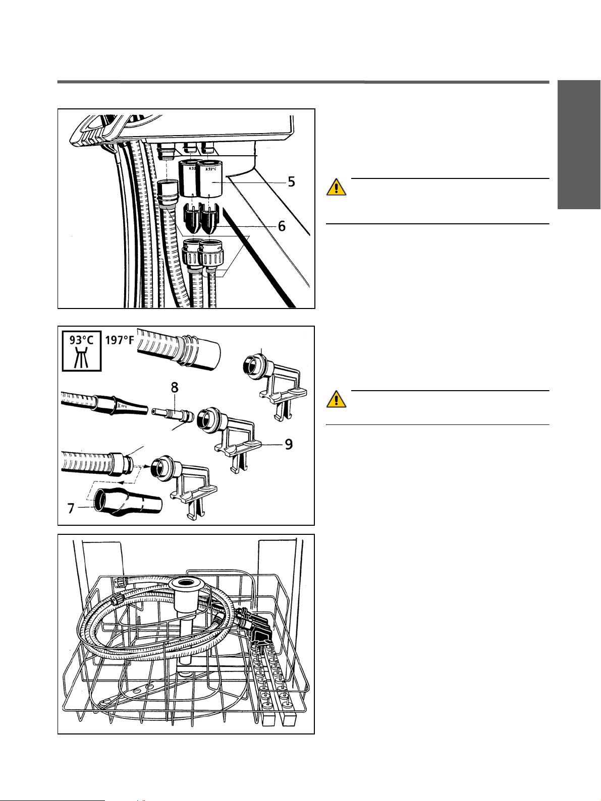
3.5 Saugschläuche reinigen
Die Schläuche von Speichelsauger und Saugkanüle
sowie der Verbindungsschlauch zur Wassereinheit können zum Durchspülen unter fließendem Wasser oder
zur Thermodesinfektion vom Helferinelement abgezogen werden.
Vorher den Arbeitsplatz AUSschalten!
Saugschläuche von den Filtergehäuse-Oberteilen (5)
abschraube n. Schläuche unter fließendem Wasser
durchspülen.
Täglich die Gehäuse-Oberteile (5) mit Filtereinsätzen
gründlich reinigen.
Die Filtergehäuse-Oberteile können thermodesinfiziert
werden.
Die Auffangbehälter (6) für Ama lgamreste bei na chlassender Saugkraft, sons t ei nmal täglich, aus den Unte r-
Fett
5
teilen (7) herausnehm en . Am alg am res te i n ei nem s epa ratem Behälter unter Wasser lagern und bei Austausch
des Amalgamrotors (Seite 14) durch Einfüllen in den
Rotor mit entsorgen.
ACHTUNG
6
7
Amalgamreste ni cht in die Sp eischal e oder in das
Waschbec k e n ents orgen!
Wenn die Schlauchoberflächen durch den Gebrauch
von Desinfektionsm itteln kle brig gew orden sind, Sch läuche mit handelsüblichem Geschirrspülmittel reinigen
und bei Bedarf danach leicht mit Talkum pudern.
Vor dem Aufstecken der Schläuche die O-Ringe an
den Anschlussstücken fetten.
ACHTUNG
V erw enden Sie nur die von Siron a zugelassene n Fet te !
Die Schläuche müssen fest einrasten.
Sollte das Gerät mit einem 3. Saugschlauch ausgestattet sein, so ist die R ei nig un g si nn gem äß d urc hz ufü hren .
59 06 511 D 3386
12 D 3386.103.01.06.01
Page 17
Sirona Dental Systems GmbH 3 Sauganlage
3.6 Saugschläuche thermodesinfizieren
3.6 Saugschläuche thermodesinfizi eren
Standardmäßig ist das Gerät mit nicht thermodesinfizierbaren Saugschläuchen ausgestattet.
Als Sonderzubehör kann es jedoch thermodesinfizier-
Fett
bare Saugschläuche besitzen. Diese sind dann türkis-
farben markiert (10).
ACHTUNG
Nur Schläuche mit dem t ürkisf arb ene n Markierungs ring
(10) sind thermodesinfizierbar!
aЙмнлЕЬ
Fett
10
Fett
Den Behandlungsplatz bitte AUSschalten.
Saugschläuche und Verbindungsschlauch von Helfe-
rinelement und Wassereinheit abziehen.
Filtergehäuse-Oberteile (5) und Auffangbehälter für
Amalgam (6) entfernen.
Handstück (7) vom Saugschlauch abziehen.
Für den Speichelsaugerschlauch muss das Zwischen-
stück (8) in den Schlauchhalter (9) gesteckt werden.
O-Ringe mit Syntheso fetten.
ACHTUNG
V erw ende n Sie n ur d ie v on Sirona zugel asse nen F e tte!
59 06 511 D 3386
D 3386.103.01.06.01
Schlauchhalter wie gezei gt auf die Schienen im The rmodesinfektor (Fa. Miele) stecken.
Saugschläuche auf die Schlauchhalter stecken und in
den zum Thermodesinfizieren vorgesehenen Drahteinsatz (Fa. Miele) legen.
Thermodesinfizieren bei max. 93 °C.
Vor dem Aufstecken der Schläuche an das Helferinelement die O-Ringe an den Anschlussstücken fetten.
Die Schläuche müssen fest einrasten.
Schlauchhalter für Thermodesinfektor Fa. Miele
Bestell-Nr. 89 18 757
13
Page 18
4 Amalgam – Abscheidung Sirona Dental Systems GmbH
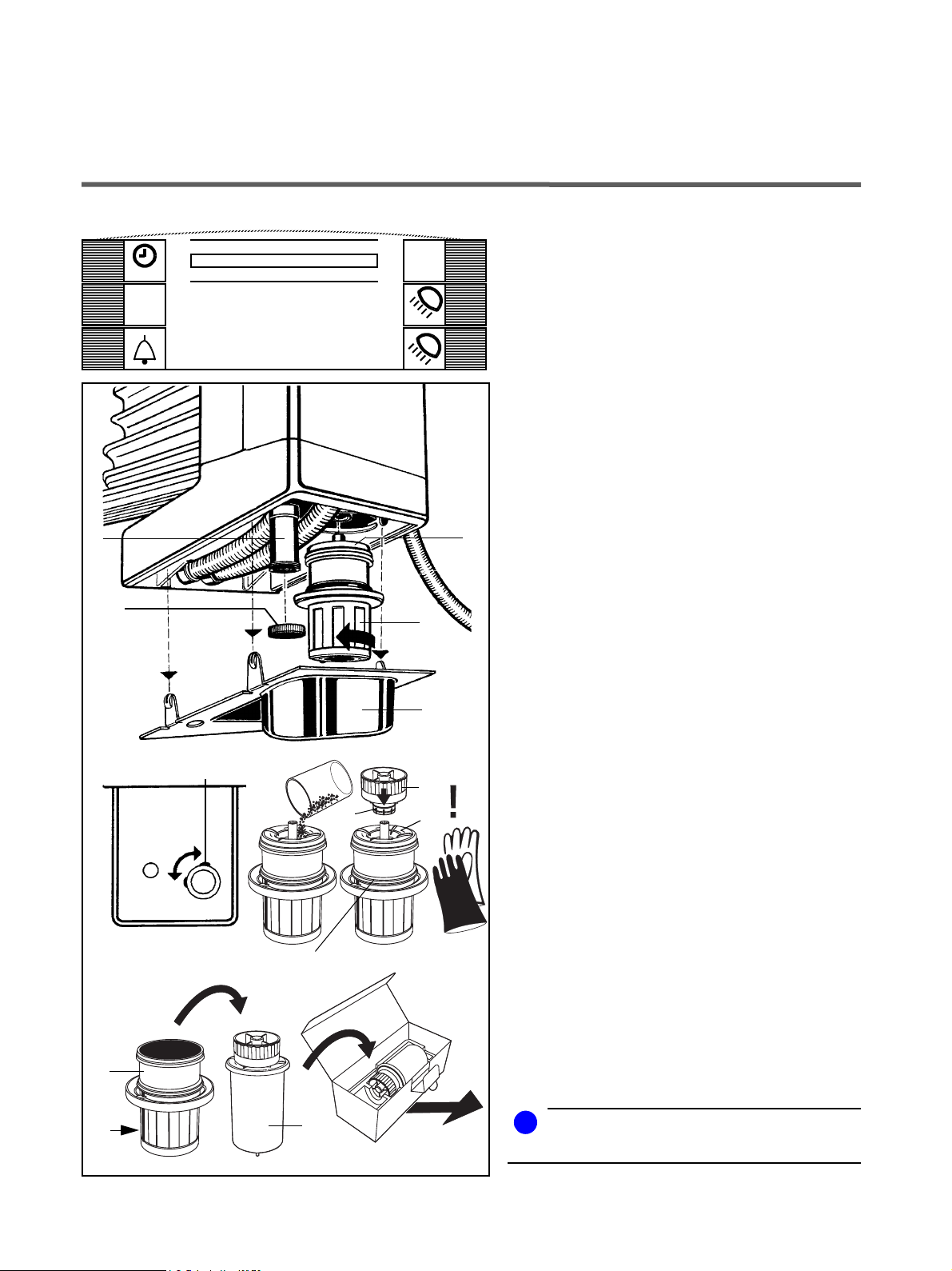
4 Amalgam – Abscheidung
Wenn auf dem Display am Arztelement die Anzeige
0m
Start
San.
42s
C
Amalgam 12:30
6
5
2
Amalgam erscheint, gehen Sie wie folgt vor:
• Desinfektion durchführen wie im Kapitel 3 „Sauganlage” beschrieben.
Gerät NICHT ausschalten!
• Untere Abdeck ung (1) v on de r W a ssere inheit abzie hen.
• Unterteil (2) des Amalgamabscheide r s mit Rotor
(3) in Pfeilrichtun g drehen, bis es sich leicht abne hmen
lässt.
Die Anzeige Amalgam blinkt auf den Displa ys .
• Gesammelte Amalgamr este aus den Saugschläuche n
und der Speischale zu r Entso rgung i n den ausge bauten Rotor einfüllen (siehe Seiten 7 und 12).
• Unterteil senkrecht halten und Transportkappe (4)
3
bis zum Einrasten aufstec ken . Da bei wird ein Bi nde-
mittel frei. Desha lb die Transportkappe nicht mehr
abnehmen!
• Rotor mit Kappe aus dem U nterteil her ausneh men
und zur Entsorgung in der Spezialverpackung versenden.
(Versandanschriften siehe Beilageblatt beim neuen
Amalgamrotor).
lösen
festziehen
ErsatzAmalgamrotor
Bestell-Nr:
14 34 138
2
7
1
7
4
O-Ring
3
Fett
• Neuen Rotor (3) in das Unterteil (2) eins etzen .
Keinen gebrauchten Rotor verwenden!
• Unterteil wieder montieren, bis zum Anschlag entgegen der Pfei lrichtung drehen . Der Ste g (7) m us s beim
Aufstec k en zum St uhl hin z eigen un d nach d em F e stdrehen zum Siphon (6).
Blinkt nach dem Ein setzen des Rotors die Anzeige
Amalgam auf den Displays weiter, so ist das Unterteil
nicht richtig verriegelt!
• Abdeckung (1) wie der an bringen .
HINWEIS: Der im Amalgamabscheider befindliche
Rotor (3) muss unabhängig vom Aufleuchten der
Anzeige Amalgam mindestens einmal pro Jahr
getauscht werden, andernf all s kön nen unang en ehm e
Geruchsentwicklungen entstehen.
Siphon
Siphon (6) bei schlec htem Abfluss der Speis chale, sonst
einmal pro Monat säubern.
Dazu muss vorhe r die Abdeckun g (1) abgenommen und
der Verschluss (5) abgeschraubt werden.
Auffangbehälter darunter halten!
Verschluss und Abdeckung wieder anbringen.
3
Entsorgung
i
HINWEIS
Tragen Sie bei diesen Arbeiten Arbei tshan dschu he!
59 06 511 D 3386
14 D 3386.103.01.06.01
Page 19
Sirona Dental Systems GmbH 5 Instrumentenschläuche
5.1 Instrumentenschläuche abnehmen, austauschen
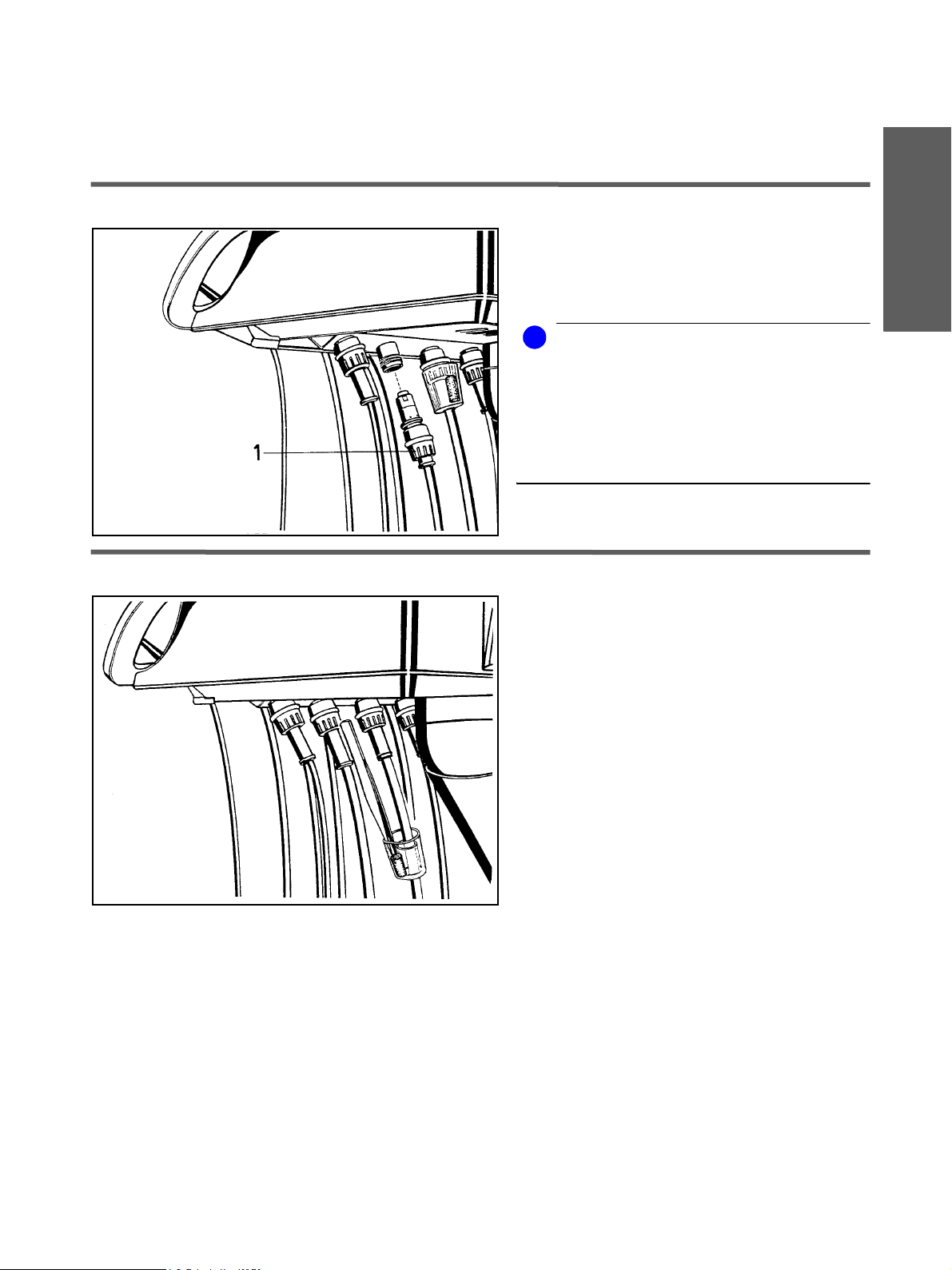
5 Instrumentenschläuche
5.1 Instrumentenschläuche abnehmen, austauschen
Dazu das Gerät AUSschalten!
Die Versorgungsschläuche der Instrumente können
nach Abschrauben der Überwurfmutter (1) einfach
abgezogen werden.
i
HINWEIS
Am rechten K upplungs stüc k darf n ur SIR OT OM, SI RO SONIC L, POLYLUX oder SIROCAM 3 bzw.
SIROCAM C ang esch losse n werd en.
Am zweiten Kupplungsstück von rechts darf nur
SIROSONIC L o der ein 4. Boh rantrieb (nur m it A us bausatz) angeschlossen werden.
aЙмнлЕЬ
5.2 Turbinenschlauch,
Am geräteseitigen Ende des Turbinenschlauchs tritt
Rückluft aus, die eine geringe Menge Turbinenöl mit
sich führt. Dieses Öl wird von der Watterolle im Klarsichtbehälter aufgefangen.
Wir empfehlen, die Watterolle wöchentlich auszutauschen.
Schieben Sie den Behälter na ch unte n und neh men di e
Watterolle heraus.
Neue Watterolle abschneiden und einsetzen.
Behälter wieder nach oben schieben.
59 06 511 D 3386
D 3386.103.01.06.01
15
Page 20
6 Desinfektionsanlage Sirona Dental Systems GmbH
6.1 Mikrobiologische Kontrolle des Wassers
6 Desinfektionsanlage
6.1 Mikrobiologische Kontrolle des Wassers
Nach mehr als einer Woche Arbeitspause durchzuführen.
Dazu verwenden Sie einen ”To tal Count Tester”. Für die
Erstkontrolle beziehen Sie drei Tester kostenlos gegen
Einsendung des beiliegenden Gutscheins.
Bitte Ihre Adresse angeben und die Serien-Nr. des
Stuhls eintragen (siehe "Installationsprotokoll /
Garantiepass"). Bei weit erem Bedarf be ziehen Sie den
Tester bitte mit
Bestell-Nr. 58 53 775.
ACHTUNG
Die Haltbarkeit be trägt m axim al 1 J a hr nach Erh alt des
”Total Count Testers”.
Die Kartonscheibe enthält de hy dratiertes Nährmedium.
Es wird durch die Probe aktiviert und dient als Nährboden für eine Reihe von Bakt erien. Die Anzahl de r Keime
gibt Aufschluß über d ie hygieni sche Besc haffenhei t des
Wassers.
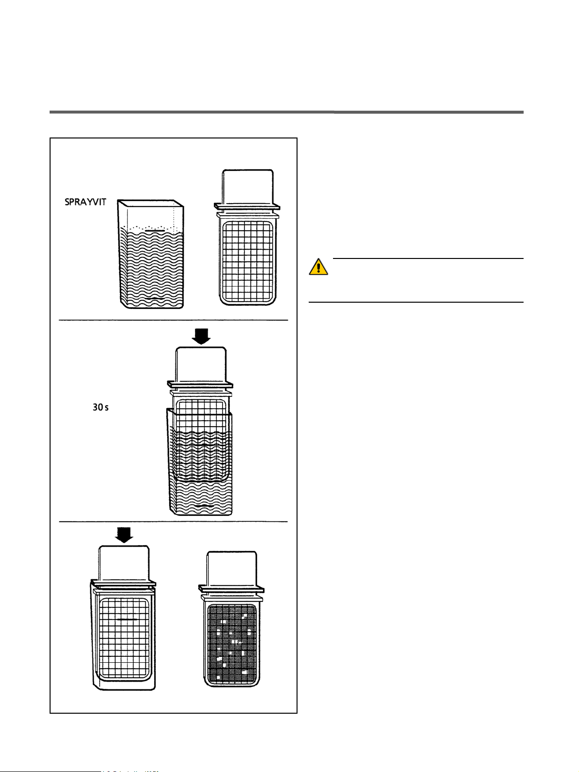
Kontrolle durchführen
• Lassen Sie an der SPRAYVIT-Spritze ca. 1 Minu te
Wasser la uf en.
• Entnehmen Sie danac h aus di eser Sp ritze e ine Wasserprobe.
Wasser bi s zur obere n Marke des Behält ers einfül len.
Zur Neutralisation des Des inf e ktionsm ittels der Wasserprobe ca. 1,5 g Fixiersalz (Na triumthiosul f at )
beimischen.
Bitte das Innere des Behält ers un d das Eintauc hteil
nicht berühren.
• Danach den Tester 30 Sekunden in das g efü llte Gehäuse eintauchen.
Die Kartonscheibe mit Nährmedium s augt n un 1 ml
der Wasserprobe auf.
• Den Tester herausnehmen und übers chüssi ges Wasser abschütteln.
Behälter ganz entlee ren.
• Tester in das leere Gehäuse einlegen z um Bebrüte n:
Entweder zwei Tage bei Raumtemper atur o der 24
Stunden bei einer Temperatur v on 3 5 °C.
• Zählen Sie danach alle auf der Oberfl äche des T esters
vorhandenen K eim e.
Liegt die Anzahl der K ei me d eutlich über 100, so ist
eine Sanierung erforderlich (siehe nächste Seite).
59 06 511 D 3386
16 D 3386.103.01.06.01
Page 21
Sirona Dental Systems GmbH 6 Desinfektionsanlage
6.2 Sanierung
6.2 Sanierung
Besondere Maßnahmen bei Zusatzgeräten Zusatzgeräte, die über die Medienleiste am Stuhl ange-
schlossen sind , we rden im Sanierfall mit desin fizie rtem
Wasser mit erhöhter Wasserstoffperoxidkonzentration
(1,4%) beaufschlagt.
Start
San.
12:30 Desinf.
0m
42s
C
ACHTUNG
Für den F all , dass die a ngesc hlos senen Geräte fü r die
erhöhte Sanierungsk onzen tration nic ht geeignet si nd,
empfiehlt Sirona, die Zusatzgeräte während der Sanierung von der Behandlung seinheit zu trennen und die Sanierung der Zusatzgeräte nach Herstell erangab en getrennt durchzuführen.
Sanierung vorbereiten
Die Sanierung ist alle 4 Wochen durchzuführen,
oder wenn die Keimzahl deu tlich über 100 Keime pro
ml liegt (siehe Abschnitt "Mikrobiologische Kontrolle des Wassers"). Nur s o kann sichergestel lt werden, dass Biofilm in den Wasserwegen wirksam
bekämpft wird.
• Das V orberei ten des Saniervo rgangs dauert ca. 10 Mi nuten.
• Wenn auf dem Di spla y am Arztelem ent Desinf. b linkt,
muss zuerst DENTOSEPT P eingefüllt werden (si ehe
Gebrauchsanweisung).
ACHTUNG
In Japan muss anstell e von DENT OSEPT P das dort verfügbare Desinfe ktionsmitt el O XYD OL verw endet we rden.
OXY DOL is t v or d em Ein füllen in di e Desin f e ktionsan lage 1:1 mit desti lliertem W as ser z u mis chen.
aЙмнлЕЬ
59 06 511 D 3386
D 3386.103.01.06.01
Danach verschwindet die blinkende Anzeige Desinf.
DENTOSEPT P
1 Karton = 6x1 Liter, Bestell-Nr. 33 18 156
• An allen Bohrantrieb en sowie am SIR OSONIC L muss
maximaler W a sser dur c hfluss eingestellt sein . Dies
ist vor Beginn jeder Sanierung z u übe rprüfen.
17
Page 22
6 Desinfektionsanlage Sirona Dental Systems GmbH
6.2 Sanierung
• Danach müssen all e Instrumente und Saugschl äuche
in ihren Köchern abgelegt sein.
Start
0m
42s
Sanierung aktivieren
San.
C
12:30
•In dem Stuhlprogramm – Dialo g de n Helferin-Dialog anwählen.
• Im Helferin-Dialog die T aste San. ca. 3 Sekunden aktivieren.
1
Sanier – Phase
1
2
3
4
1
3
4
2
3
4
5
6
3
4
Die Aktivierung ist nur möglich, wenn genügend
DENTOSEPT P im Nachfüllbehälter ist, und wenn alle
Instrumente fest in der Instrumentenablage sitzen.
Gegebenenfalls DENTOSEPT P nachfüllen und d en Sitz
der Instrumente prüfen.
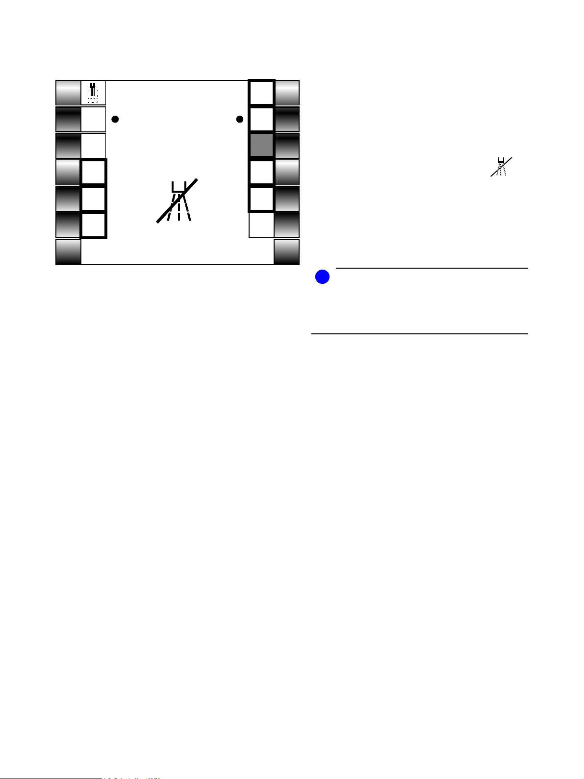
Der Sanier-Dialog erscheint.
Sanier – Phase 1
Auf den Displays werden während des Sani erablaufs die
Sanier – Phasen 1 bis 6 angezeigt.
Die linke Tastenreihe kennzeichnet die Ablageköcher
am Helferinelement.
Die rechte Tastenreihe kennzeichnet die Ablageköcher
am Arztelement.
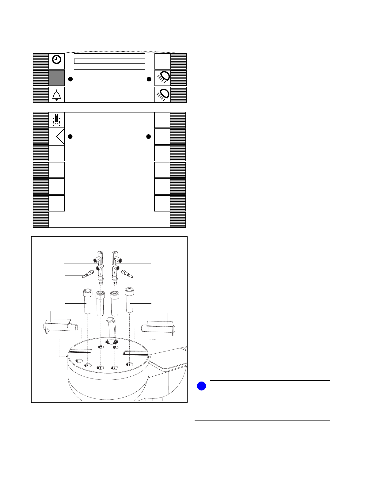
Vorbereitung der Sanierhaube
• Die Sanierhaube mit Deckel auf die Speischa le aufsetzen. Der Behälter der Sa nierha ube m uss im mer sau ber sein!
• Die Reinigungsad apter fü r die I nstrumente nku pplun gen (1), SPRAYVIT -Ventilkörper (2) und Saugschläuche (3) wie gezeigt bis zum Anschlag in die Sa nierhaube stecken.
1
2
1
2
Die Adapter für die Instrumen tenkupplungen sind analog
zu den Schlauchkupplungen farbig markiert.
SL-Motor: grün
Elektromotoren mit Schnittstelle gemäß ISO 3964 wie
EL 1 Motor: blau
Turbine: weiß
SIROSONIC L: rot
• Für den Speichelsaug erschlauch muss d as Zwischenstück (4) in d en Rein igungs adapt er ges tec kt w erd en.
i
HINWEIS
Um ein Verwinden und Überdehnen der Schläuche zu
vermeiden, sollte die Anordnung d er Reinigungsada pter
von links na ch rechts der Anordnu ng der Instrumente am
Arztelement ents preche n.
59 06 511 D 3386
18 D 3386.103.01.06.01
Page 23
Sirona Dental Systems GmbH 6 Desinfektionsanlage
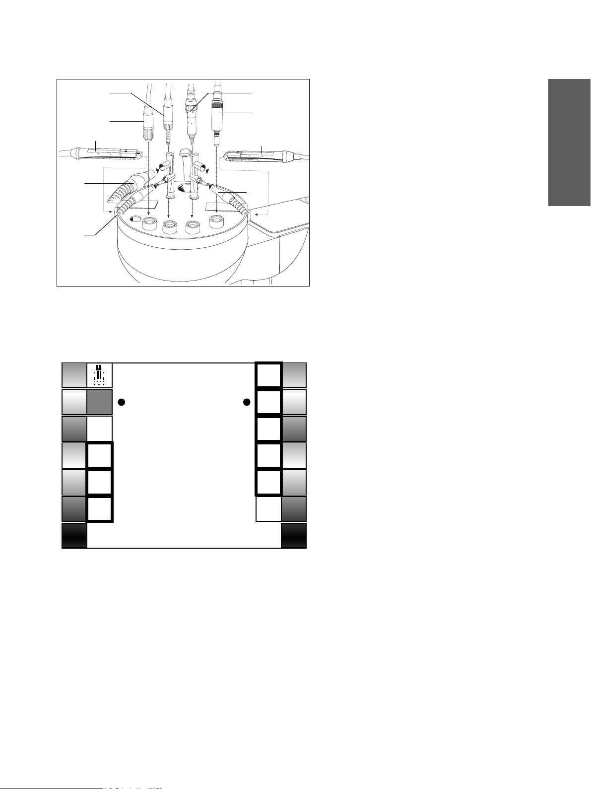
Die Sanierung der Wasserwege erfolgt grundsätzlich ohne aufgesteckte Behandlungsinstrumente!
• Behandlungsinst rumente v on d en K up pl ungen und
SPRAYVIT-Hülsen von den Ventilkörpern abziehen.
• SPRAYVIT-Schläuche mit Ventilkörpern (5) von Arztund Helf erineleme nt rec hts un d link s bis z um Anschlag in die Adapter stec ken (Ventilhebel nach oben,
Rastknopf nach unten).
• Folgende K up plunge n f arb gleic h in d ie zug ehörigen
Adapter bis zum Anschlag bzw. Einrasten stecken:
– SL-Motoren (6)
– Elektromotoren mit Schnittstelle ISO 3964 wie
EL 1 Motor (7),
– Turbine (8) und
– SIROSONIC L (9)
Der Farbring am Instrumentenschlauch befindet
sich an der Überwurfmutter.
• Saugdüsen abziehen .
Saugschlauch (10) u nd Spei chels augers chla uch un d
wenn vorha nden 3. Saugschlauc h (11) seitlich am Rei nigungsadapter a ufstec k e n.
,
10
11
8
6
7
9
5
5
11
11
6.2 Sanierung
aЙмнлЕЬ
San.
Start
1
2
3
4
Sanier – Phase
1
Start der Sanierung
1
2
3
4
5
6
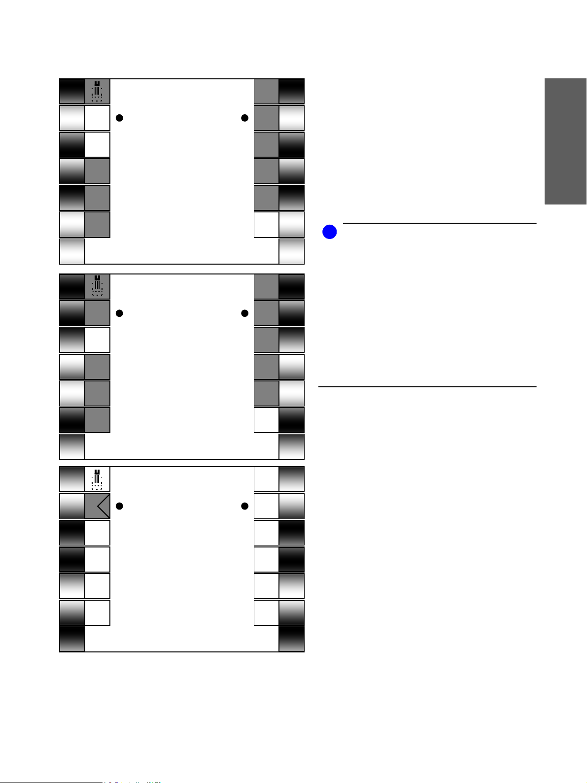
Nach der Entnahme de r Instrumente und Sch läuche aus
ihren Köchern ist die zugehörige Zahlenanzeige dick
umrahmt (links Helferin-, rechts Arztelement).
In der linken und rechten Zahlenreihe des Displays entsprechen die Zahlen jeweils den Ablageköchern von
Helferin- und Arztelement (Zählung der Ablageköcher
jeweils von links nach rechts).
Alle nicht entnommenen und nicht wasserführenden
Instrumente (POLYLUX, SIROTOM, SIROCAM) bleiben
bei der Sanierung unberücksi chtigt. Die entsprechenden
Zahlenanzeigen werden nicht dick eingerahmt.
• Aktivieren Sie nun die Taste San. Start.
Es erscheint San. Stop.
Der Saniervorgang beginnt.
59 06 511 D 3386
D 3386.103.01.06.01
19
Page 24
6 Desinfektionsanlage Sirona Dental Systems GmbH
6.2 Sanierung
Sanier–Phase 2
San.
Stop
1
Sanier – Phase
2
1
2
3
Zunächst wird überprüft, ob an den Instrumentenkupplungen max. Wasserdurchfluss gegeben ist .
Ist der Wasserdurc hfluss nicht gegeben, e rtönt ein akustisches Signal. Die Anzeige des dazugehörige n Köchers
blinkt und im Display erscheint das Zeichen:
2
3
4
4
5
6
(Beispiel Köcher 3 am Arztelement).
In diesem Fall öffnen Sie den Wasserreg ler des entspre-
chenden Schlauchs an der Instrumentenkupplung. Lassen Sie dabei den jeweiligen Schlauch im Adapter stekken. Sobald d as System den Wasserdurchfluss erkennt,
wird die Sanierung automatisch fortgesetzt.
i
HINWEIS
Wenn Sie n ach Ertönen des aku stische n Signa ls di e
blinke nde Taste aktivieren, oh ne den Wasserregle r zu
öffnen, fährt das Sanierungsprogramm f ort. Der ent-
sprechende Wasserweg wird nicht saniert.
Sanier–Phase 3
Danach wird das Wasser über die Mund glasf üllung aus
dem Wassertank der Wassereinheit gepumpt.
Sanier–Phase 4
Anschließend wird der Behälter automatisch mit
DENTOSEPT P gefüllt.
Damit werden dann die Instrumentenschläuche, die
SPRAYVIT-Schläuche mit Ventilkörpern und die Mundglasfüllung durchgespült. Nach dem jeweiligen Spülvorgang werden die Köcheranzeigen dunkel dargestellt.
59 06 511 D 3386
20 D 3386.103.01.06.01
Page 25
Sirona Dental Systems GmbH 6 Desinfektionsanlage
6.2 Sanierung
San.
Stop
1
2
3
4
San.
Stop
1
2
3
4
24:00
Sanier – Phase
5
Sanier – Phase
6
1
2
3
4
5
6
1
2
3
4
5
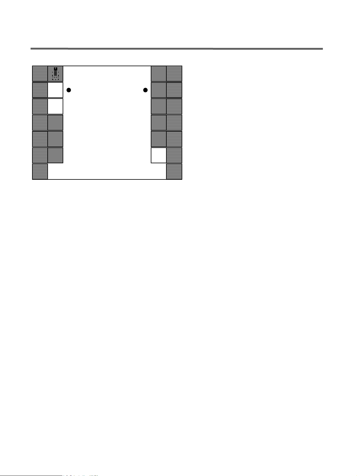
Sind alle Zahlenanze igen der zur Sanier ung entnomme nen Instrumente dunkel dargestellt, erscheint oben auf
dem Display die Einwirkzeit von 24:00 Stunden.
• Das Gerät muß n un für mind estens 24 Stunden
AUSgeschaltet werden aber nic ht länger als drei T age).
Lassen Sie alle Sc hläuche in den Adapt ern der Sanierhaube stec k en.
• Schalten Sie nach m indestens 2 4 Stunde n da s Ge rät wieder EIN.
i
HINWEIS
Falls Sie nach Sanier–Phase 5 die Wasserzufuhr für den
Behandlungsplatz ge sperrt haben, öffnen Sie v o r Wieder- Inbetriebnahme (nach Ab lauf d er 24 St unden) die
Wasserzufu hr wi eder. Schalten Sie danach das Gerät
EIN.
Lassen Sie die Schläuch e weiterhin in den Adaptern der
Sanierhaube stec k en . Das Sa nierprogr amm w ird n un
automatisch zu Ende geführt.
Falls Sie den Behandlungs platz bereits v or Ablauf de r 24
Stunden einschalten (die fehlende Zeit is t dann im Di splay dargest ellt), i st nac h Eins chal ten des Gerätes die
Taste San. Stop zu aktivieren. Das Sanierprogr amm
wird dann zu Ende geführt.
aЙмнлЕЬ
Sanier–Phase 6
Sanier–Phase 5
6
Die Schläuche und die Mundglasfüllung werden mit
Wasser gespült. Dies dauert einige Minuten.
Die Köcheranzeigen erscheinen nach der Spülung wieder dick umrahmt.
1
2
3
4
59 06 511 D 3386
D 3386.103.01.06.01
Sanier – Phase
1
1
2
3
4
5
6
• Sobald auf dem Dis pla y wiede r San ier–Phase 1 erscheint, können di e S chläuche wie der in den en tspr echenden Köchern abgelegt we rden. Da raufh in erscheint links ob en auf dem Di spla y der Rü c kstel lpf eil .
• Aktivieren Sie n un de n Rü c kstel lpf eil zum Verlassen
des Sanier-Dialogs.
Das Gerät ist wieder betriebsbereit.
21
Page 26
6 Desinfektionsanlage Sirona Dental Systems GmbH
6.3 Sanier-Vorgang unterbrechen
6.3 Sanier-Vorgang unterbrechen
Während des Sanier-Vorganges ist auf den Displays
San. Stop angezeigt. Mit dieser Taste können Sie die
Sanierung unterbrechen.
Es erfolgt dann die Spülung der Schläuche mit Wasser
wie beschrieben. Nach dem Spülvorgang und dem
Erscheinen de s Rückstellp feils auf dem Display i st nach
Ablegen der Instrumente das Gerät wieder betriebsbereit.
San.
Stop
1
2
24:00
Sanier – Phase
5
1
2
3
4
3
4
5
6
59 06 511 D 3386
22 D 3386.103.01.06.01
Page 27
Sirona Dental Systems GmbH 7 Oberflächen / O-Ringe
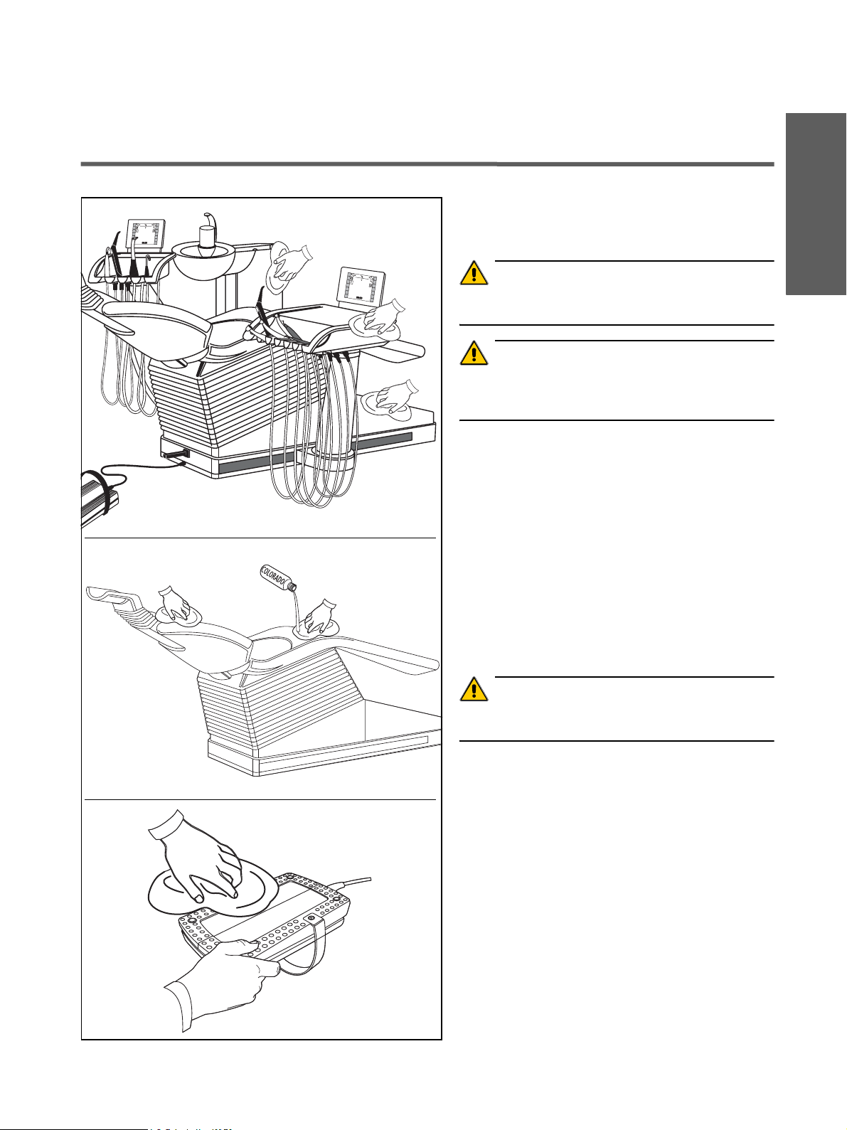
7 Oberflächen / O-Ringe
Desinfizieren
Die Oberflächen (außer Polster) sind mit Flächendesinfektionsmitteln sprüh- und wischdesinfizierbar.
ACHTUNG
V erw ende n Sie n ur d ie v on Sirona zugel asse nen Des infektionsmittel !
ACHTUNG
Bei Berührung der Tasten auf den Displays (bei ein geschaltetem Gerät) k önnen sich die Ei nstellun gen v e rändern!
Reinigen
Entfernen Sie Schmutz und Desinfe ktion sm itte l-R ü ck stände regelmäßig mit milden, handelsüblichen Reini-
gungsmitteln.
Verwenden Sie dazu bitte keine farbig en Tücher, diese
können z. B. in Verbindung mit Desinfektionsmitteln zu
Verfärbungen der Geräteobe rflä ch en führe n!
Keine Flüssigkeit in Lüftungsschlitze laufen lassen!
aЙмнлЕЬ
Polster
Die Kunstlederpolster müs sen wöchentlich gepfl egt werden.
Reinigen:
ACHTUNG
V erw ende n Sie n ur d ie v on Sirona zugel asse nen Rei nigungsmittel !
Desinfizieren:
Die Polster sind mit Alkohol 50% (Ethanol-Wasser-
Gemisch) zu desinfizieren.
Pflege der O-Ringe
• nur mit zugel asse nen F e tten
• keine Vaseline oder Sil ik onf e tte v erw en den, d iese
beschädigen die O -Ri nge!
Fußschalter
Bodenplatte unten feucht rein ige n
Medikamentenbeständigkeit
Viele Medikamente kön ne n aufgru nd der hoh en Konzentration und der verwendeten Wirkstoffe die Oberflächen anlösen, anätzen, bleichen oder verfärben.
59 06 511 D 3386
D 3386.103.01.06.01
Nur ein sofortiges Abwischen mit einem feuchten
Tuch kann einen größeren Schaden verhindern!
23
Page 28
7 Oberflächen / O-Ringe Sirona Dental Systems GmbH
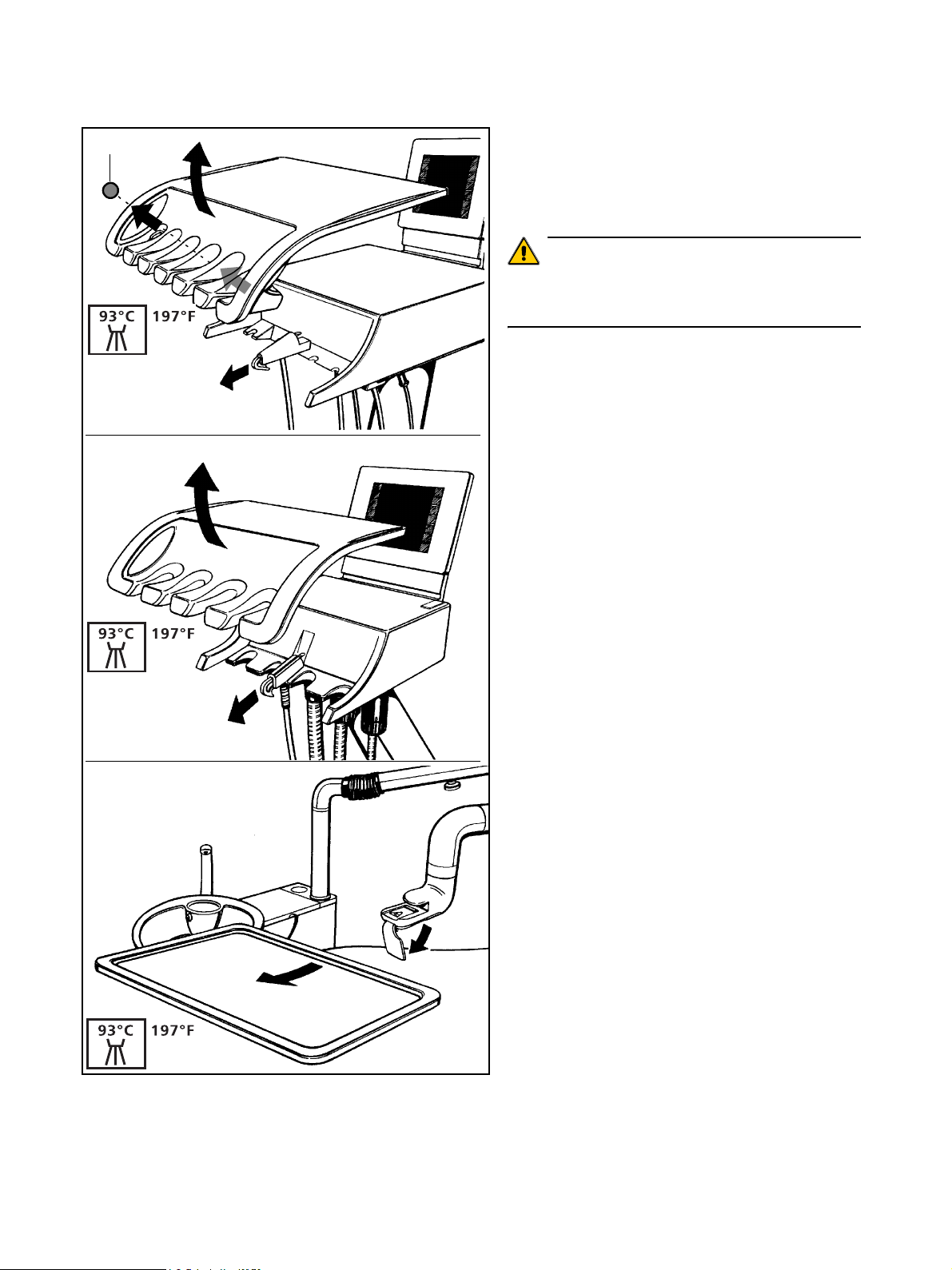
12
Zum leichteren Reinigen oder
Thermodesinfizieren bei 93 °C können die Instrumentenablagen v on Arzt- und Helf erinelement sowie
das Instrumententra y abgenom me n wer d en.
ACHTUNG
Die Instrumentenab lagen v on Arzt- und Hel fe rinelement
müssen alleine thermodesinfiziert werden, da sonst
V erfär b unge n auftr eten k önnen.
Eine evtl. vorhandene Verschlusskugel (12) in einer
nicht belegten Ablageklaue kann zum Reinigen oder
Thermodesinfiziere n einfach von hinten herausgedrückt
werden.
59 06 511 D 3386
24 D 3386.103.01.06.01
Page 29
Sirona Dental Systems GmbH 8 POL YLUX - Kaltlicht Handstüc k
8.1 Pflege und Reinigung der Griffhülse
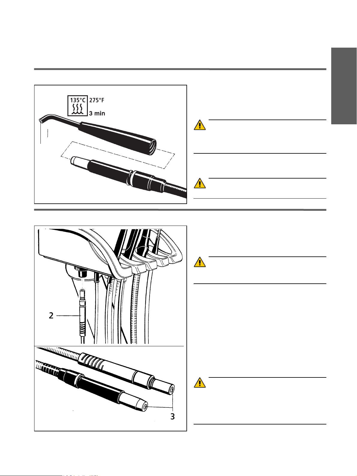
8 POLYLUX - Kaltlicht Handstück
8.1 Pflege und Reinigung der Griffhülse
Die Griffhülse mit Glasfaserstab kann zum Reinigen
und Sterilisieren vom Handstück abgeschraubt werden
(gegen den Uhrzeigersinn).
Sterilisation im Autoklaven bei 135 °C, 2,1 bar.
ACHTUNG
150 °C KEINESFALLS überschreiten! KEINE Ultraschall-Reinigung und KEI NE ch emische Dampf- Sterili-
1
sation vornehmen!
Vor jeder Sterilisation die Lichta us tritt sfl äc he (1) mit
Alkohol (50%) vorreinigen.
ACHTUNG
Griffhülse NICHT i n De sinf e ktions lösu ngen l egen!
aЙмнлЕЬ
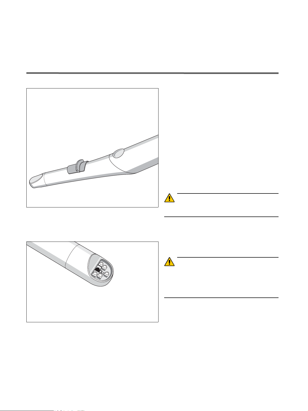
8.2 Pflege und Reinigung des Lichtleiters
Der Lichtleiter (Handstückschlauch) kann zum Reini-
gen und Desinfizieren aus dem Lampenmodul an der
Unterseite des Arzt- bzw. Helferinelementes herausgezogen werden.
ACHTUNG
Immer am grauen Knickschutz (2) anfassen,
NIE am Schlauch!
Handstückschlauch nicht quetschen, verdrehen
oder knicken! Einen minimalen Biegeradius von
80 mm nicht unterschreiten.
Reinigen
• mit Alkohol (50%) oder mit einer wäßrigen Spülmittellösung.
• Lichtein- bzw. -austrittsfl ächen (3) mit Alk o hol (5 0%)
reinigen.
Wischdesinfektion
kann durchgeführt werden.
ACHTUNG
Den Flüssigk eitslic htleit er KEINESFALLS sterilisieren
oder thermodesinfizieren!
NICHT in ein Flüssigk eitsbad leg en und KEINE Ultraschall-Reinigung v o rnehmen!
59 06 511 D 3386
D 3386.103.01.06.01
25
Page 30
9 Videokamera SIROCAM 3 / SIROCAM C und Monitor Sirona Dental Systems GmbH
9.1 Pflege und Reinigung der SIROCAM 3
9 Videokamera SIROCAM 3 / SIROCAM C
und Monitor
9.1 Pflege und Reinigung der SIROCAM 3
Die ergonomisch gefo rmte Titanhüls e der Kamera weist
wenige Trennfugen auf. Ihre Formgebung berücksichtigt
hygienische Anforderungen und hat keine schwer
zugänglichen Stellen.
Reinigen
Entfernen Sie Schmutz und Desinfektionsmittel-Rückstände regelmäßig mit milden, handelsüblichen Reinigungsmitteln.
Verwenden Sie dazu bitte keine farbigen Tücher, diese
können, z. B. in Verbind ung mit Des infektionsmit teln, zu
Verfärbungen der Oberflächen führen!
Desinfizieren
Die Kamera ist wischdesinfizierbar.
ACHTUNG
V erw end en Sie nur d ie v on Si rona z ugelas senen R einigungsmittel !
SIROCAM 3 mit weichem Tuch abwischen.
Schützen Sie das Objektivfenster vor Verkratzen und
reinigen Sie es mit eine m fusselfreien weichen Tuch.
ACHTUNG
Das Kameraha ndstü c k mit dem K abe l ist NICHT s terilisierbar oder thermodesinfizierb ar!
Die Kamera darf N ICHT bespr üht ode r in Fl üssig k eiten
getaucht werden !
59 06 511 D 3386
26 D 3386.103.01.06.01
Page 31

Sirona Dental Systems GmbH 9 Videokamera SIROCAM 3 / SIROCAM C und Monitor
9.2 Pflege und Reinigung der SIROCAM C
9.2 Pflege und Reinigung der SIROCAM C
Reinigen
Entfernen Sie Schmutz und Desinfekti on sm itte lRückstände regelmäßig mit milden, handelsü bli ch en
Reinigungsmitteln.
Verwenden Sie dazu bitte keine farbigen Tücher, diese
können, z. B. in V erbindung mit D esinfektion smitteln, zu
Verfärbungen der Oberflächen führ en!
Desinfizieren
Die Kamera ist wischdesinfizierbar.
ACHTUNG
V erw ende n Sie n ur d ie v on Sirona zugel asse nen Rei nigungsmittel !
SIROCAM C mit weichem Lappen abwischen.
ACHTUNG
Das Kamerahands tüc k m it dem Ka bel is t NICH T st erilisierbar oder thermodesinfizierba r!
Die Kamera darf NIC HT bes prüht o der in Alk ohol getaucht werden!
aЙмнлЕЬ
9.3 Pflege und Reinigung des Monitors
Reinigen
Entfernen Sie Schmutz und Desinfe ktion sm itte l-R ü ck stände regelmäßig mit milden, handelsüblichen Reini-
gungsmitteln.
Verwenden Sie dazu bitte keine farbigen Tücher, diese
können, z. B. in V erbindung mit D esinfektion smitteln, zu
Verfärbungen der Oberflächen führ en!
Desinfizieren
Glasscheibe und G ehäus e des M onitor s sind mit ein em
weichen Lappen wischdesinfizierbar.
ACHTUNG
V erw ende n Sie n ur d ie v on Sirona zugel asse nen Rei nigungsmittel !
ACHTUNG
Den Monitor k eines f alls mit De sinf e ktion s- ode r Reinigungsmitteln be sprühe n!
59 06 511 D 3386
D 3386.103.01.06.01
27
Page 32

10 Sicherheitsschalter überprüfen Sirona Dental Systems GmbH
10 Sicherheitsschalter überprüfen
Im Interesse der Sicherheit von Praxisteam und Patienten überprüfen Sie bitte alle 6 Monate die im Gerät ein-
gebauten Sicherheitsschalter.
Fahren Sie dazu den Stuhl bzw. die Rückenlehne
jeweils nach unten.
• Beinauflage anheben:
Stuhlbewegung st oppt, d anach K orre ktur be wegu ng
nach oben für ca. 3 s.
• Rückenlehne anheb en:
Rückenleh nenbe w egu ng st oppt, d anach Korrekturbewegung nach oben für ca . 3 s .
• Motorische K opfstütze a nheben:
Rückenleh nenbe w egu ng st oppt, d anach Korrekturbewegung nach oben für ca . 3 s .
• Schwenkbare Speischa le eins chw enken (Opt ion):
Stuhlbewegung st oppt.
ACHTUNG
Wenn einer der Sicherheitsschalter die Stuhlbewegung
bzw . die Rüc k en lehnen be w egung nicht stopp t, darf m it
dem Behandlungspl atz ni cht w eit ergearb eitet w erden!
Rufen Sie b itte Ihre n Servicetechni k er.
59 06 511 D 3386
28 D 3386.103.01.06.01
Page 33

Page 34

ыеЗЙкмеЦЙе=бг=wмЦЙ=нЙЕЬеблЕЬЙк=tЙбнЙкЙенпбЕвдмеЦ=озкДЙЬ~днЙеK
«=pбкзе~=aЙен~д=pулнЙгл=dгДe=OMMN pйк~ЕЬЙW=ЗЙмнлЕЬ= mкбенЙЗ=бе=dЙкг~еу
a=PPUSKNMPKMNKMSKMN===NMKOMMQ ûKJkêKW= NMR=NNR fгйкбг¨=Йе=^ддЙг~ЦеЙ
pбкзе~=aЙен~д=pулнЙгл=dгДe
áå=íÜÉ=rp^W áå=`~å~Ç~W
c~Дкбвлнк~≈Й=PN
aJSQSOR=_ЙелЬЙбг
dЙкг~еу
пппKлбкзе~KЗЙ
páêçå~=aÉåí~ä=póëíÉãë=ii`
QUPR=páêçå~=aêáîÉI=pìáíÉ=NMM
`Ь~кдзннЙI=k`=OUOTP
rp^
páêçå~=`~å~Ç~
PORM=oáÇÖÉï~ó=aêáîÉ=J=råáí=R
jáëëáëë~ìÖ~I=låí~êáç=iRi=RvS
`~å~Ç~
_ЙлнЙддJkкK
RV=MS=RNN=a=PPUS
Page 35

H
`N
`~кЙ=~еЗ=`дЙ~ебеЦ=Ду=нЬЙ=mк~ЕнбЕЙ=qЙ~г
bеЦдблЬ
Page 36

Sirona Dental Systems GmbH
Care and Cleaning by the Practice Team Dear User,
To maintain the value and safe fu nctioning of your treatment center it is necessary to care for, to clean and to
disinfect this regularly.
The work steps you have to perform are descri bed in this
document.
Maintenance of the treatment center by the
service engineer
Despite the outstandin g qualit y of your treatme nt center
and the regular care performed by the practi ce team,
inspections and maintenance by the service engineer
are required at predetermined intervals to ensure its
operational reliability and safety.
Please refer to your operating instructions for details.
+
Your C1
Team
59 06 511 D 3386
2 D 3386.103.01.06.02
Page 37

Sirona Dental Systems GmbH
Contents
1 Connection box ......................................................................................................................... 6
2 Cuspidor..................................................................................................................................... 7
3 Vacuum system......................................................................................................................... 8
3.1 Care.................................................................................................................. 8
3.2 Disinfection when using dry aspiration.............................................................. 8
3.3 Disinfection when using wet aspiration ........................................................... 10
3.4 Suction handpieces......................................................................................... 11
3.5 Cleaning the suction hoses............................................................................. 12
3.6 Thermodisinfecting the suction hoses............................................................. 13
4 Amalgam sepa r a tion... ............. .. ... ............. .. ............. ... ............. .. .. .............. .. ............. .. ........... 14
5 Instrumen t h o s es .. .............. .. ............. .. .............. .. .. ............. .. .............. .. ............. .. .............. ...... 15
5.1 Removal/replacement of instrument hoses..................................................... 15
5.2 Turbine hose................................................................................................... 15
6 Disinfect io n s ys t e m . .. ............. ............. ... ............. .. ............. .. .............. .. ............. .. .............. . ..... 16
6.1 Microbiological water test................................................................................ 16
6.2 Sanitation........................................................................................................ 17
6.3 Aborting the sanitation process....................................................................... 22
7 Surfaces / O-rings....... ................................................. ............................................................ 23
8 POLYLUX fiber optic light handpiece.................................................................................... 25
8.1 Care and cleaning of the handle sleeve.......................................................... 25
8.2 Care and cleaning of the light guide............................................................... 25
9 SIROCAM 3 / SIROCAM C video camera and monitor......................................................... 26
9.1 Care and cleaning of the SIROCAM 3............................................................ 26
9.2 Care and cleaning of the SIROCAM C........................................................... 27
9.3 Care and cleaning of the monitor.................................................................... 27
10 Checking the safety switches ................................................................................................ 28
bеЦдблЬ
59 06 511 D 3386
D 3386.103.01.06.02
3
Page 38

Sirona Dental Systems GmbH
59 06 511 D 3386
4 D 3386.103.01.06.02
Page 39

Sirona Dental Systems GmbH
Overview
The numbers indicated in the overview correspond
3
8
2
47
6
to the chapter numbers in the table of contents.
Thus you can easily find the work to be performed in
this document.
1 Connection box
2 Cuspidor
3 Vacuum system
4 Amalgam separation
5 Instrument hoses
6 Disinfection system
1
5
7Surfaces
9
8 POLYLUX fiber optic light handpiece
SIROCAM 3 / SIROCAM C video camera
9
monitor
10 Checking the safety switches
Please carry out care and maintenance of the following
products as described in the relevant operating
instructions supplied in each case.
• SPRAYVIT syringe ,
• T1 TITAN, T1 CLASSIC and T1 LINE str aight and
contra-angle handpieces,
• Electric motors,
• Turbines,
• SIROSONIC L scaler,
• SIROTOM electrosurgical unit,
• SIROCAM 3 video camer a,
• SIROLUX FANTASTIC unit lamp
bеЦдблЬ
59 06 511 D 3386
D 3386.103.01.06.02
5
Page 40

1 Connection box Sirona Dental Systems GmbH
1 Connection box
Should you notice changes of the media flows, please
check the filters for water and air (1) for permeability.
Replace them if necessary.
Replace the filters (1) for water and air.
To do so, first turn t he main switch OFF. Pry o ff the cover
(2) with a screwdriver.
OFF
Remove the screw caps (3) and replace the filters.
Filter
Order No. 14 43 436
The main fuse (4) is located below the air filter.
Unit main fuse for 230V AC:
T 6.3A H, 250V AC, Order No. 10 77 452
Unit main fuse for 100V AC / 115V AC:
T 10A H, 250V AC, Order No. 10 77 460
59 06 511 D 3386
6 D 3386.103.01.06.02
Page 41

Sirona Dental Systems GmbH 2 Cuspidor
2 Cuspidor
After each patient
Clean the cuspidor.
ATTENTION
Amalgam
5
6
Grease
Use only cleaning ag ents whi ch hav e be en appro ved by
Sirona!
ATTENTION
Do not use an y do mest ic cl eaning and c are ag ent s.
Foaming d omes tic c leanin g agen ts lea d to foam and
water being dr a wn in to the dry aspira tion s ystem,
resulting in damage to the suction machine.
Daily before the mid-day break a nd
after the practice has closed
Remove the gold trap (5) and clean it.
Store amalgam residues under water in a separate
closed container. When the amalgam rotor is replaced
(see page 14), put the residues into the rotor for
disposal.
The cuspidor must be filled with at least 1liter of water
for rinsing after the cleaning process.
bеЦдблЬ
ATTENTION
Amalgam residues in the gol d trap must not be disposed
of in the cuspidor o r th e sink!
Weekly
Pull out the tumbler outlet (6) or the hydrocolloid
adapter, if any, and clean it.
Before refitting the tumbler outlet or the hydrocolloid
adapter, lightly lubricate the O-rings.
ATTENTION
Use only lubricants w hich ha v e be en app roved by
Sirona!
59 06 511 D 3386
D 3386.103.01.06.02
7
Page 42

3 Vacuum system Sirona Dental Systems GmbH
3.1 Care
3 Vacuum system
3.1 Care
After each patient
To ensure that the vacuum system is always ready for
use, a large glass of col d, clear wate r must be as pirated
through the used suction hoses after each patient ,
especially after each intervention during which the
patient loses blood and after using hydrogen peroxide
).
(H
2O2
In long-lasting treatments a glass of water must be
aspirated at least every 60 min.
3.2 Disinfection when using dry aspiration
Daily before the mid-day break and
after the practice has closed
The vacuum system is subjec ted dai ly to ge rm-c arry in g
secretions, saliva and blood.
For hygienic reasons the system must therefore be
disinfected with a detergent/disinfectant approved by
Sirona.
ATTENTION
Use only cleani ng an d disi nfecting agent s wh ich h ave
been approved by Sirona !
Do not use any detergents or other disinfectants!
• Prepare the cleaning so lution in a separ at e con tainer
according to the manufacturer’s instructions and mix
thoroughly.
• Remove th e gold tr ap .
• Clean the cuspidor.
• Plug in the cleaning a dapter up to th e stop . F or the sa -
8
liva ejector ho se , inse rt the intermediate pie ce (8) in
the cleaning adapter .
• Fill the cleaning solut ion
cuspidor (ap prox.
• Remove th e suc tion h oses f rom the ir rece ptacl es and
attach them to the side o f the c leani ng ada pter, if possible sim ultane ously.
• The cleaning solu tion i s asp ir ated.
The cleaning process takes several minutes.
up to the filling limit (A) i n the
0.75 liters).
A
59 06 511 D 3386
8 D 3386.103.01.06.02
Page 43

Sirona Dental Systems GmbH 3 Vacuum system
• After the cleanin g process, at l east 1 liter of wa ter must
be filled into th e cuspid or and aspir a ted in order to remove a ny disi nf ect ant res idues f rom th e suc tion h oses.
• At the end of the c leani ng proc ess , pu ll off the ho ses
and deposit them in th eir rec eptac les .
• Remove the cleaning adapter.
• Finally, refit the gold trap.
3.2 Disinfection when using dry aspiration
bеЦдблЬ
59 06 511 D 3386
D 3386.103.01.06.02
9
Page 44

3 Vacuum system Sirona Dental Systems GmbH
3.3 Disinfection when using wet aspiration
3.3 Disinfection when using wet aspiration
With this system, the automatic separating device and,
where appropriate, t he amalgam separator ar e not
integrated into the water un it. Both separation processe s
are performed centrall y.
Daily before the mid-day break and
after the practice has closed
• Flush through the vacuum system as described under
3.2 Disinfection for dry aspiration wi th a s uitab le
cleaning and dis inf ec tion ag ent.
• After the liquid has be en a spirate d t hrough the tw o
suction hoses, re mo v e the c leanin g adap ter.
• After this, pour 1 liter o f disi nfectant solut ion in to t he
cuspidor while simultaneously pressing the button
(arrow) for approx. 10 seconds .
Pressing the b utton enab les the clean ing and d isinf ectant liquid fro m the cu sp idor to reach the v a cuum line
via the cuspidor v al v e .
simultaneously
• Finally, refit the gold trap .
ATTENTION
Use only cleani ng an d disi nfecting agent s wh ich h ave
been approved by Sirona!
Do not use any detergents or other disinfectants!
59 06 511 D 3386
10 D 3386.103.01.06.02
Page 45

Sirona Dental Systems GmbH 3 Vacuum system
3.4 Suction handpieces
3.4 Suction handpieces
Sterilization
The suction cannula (1),
the intermediate piece (2),
5
2
3
1
Gr
e
s
a
e
4
3
the suction handpiece (3),
the saliva ejector handpiece (4)
and the surgical suction cannula (5)
can be sterilized.
Sterilize only in an autoclave at 135°C, 2.1 bar.
Thermodisinfection
All parts can be thermodisinfected at 93°C (197°F).
Disinfection
All parts can be sprayed or wiped with a disinfecting
solution.
ATTENTION
Use only cleaning ag ents whi ch hav e be en appro ved by
Sirona !
Grease the O-rings at the joints afterwards!
bеЦдблЬ
Weekly
G
r
e
a
s
e
Separate the suction handpiece at the joint, clean the
handpiece, and grease the joints.
ATTENTION
Use only lubricants w hich ha v e be en app roved by
Sirona!
59 06 511 D 3386
D 3386.103.01.06.02
11
Page 46

3 Vacuum system Sirona Dental Systems GmbH
3.5 Cleaning the suction hoses
3.5 Cleaning the suction hoses
The hoses of the saliva ejector and suction cannula as
well as the connection hose to the water unit can be
pulled off from the assistant element for rinsing under
running water or thermodisinfection.
Switch the unit OFF first!
Unscrew the suction hoses from the top parts (5) of the
filter housings. Rinse the hoses under running water.
The top parts of the housings (5) with filter inserts must
be thoroughly cleaned every day.
The top parts of the filter housings can be
thermodisinfected.
Remove the amalgam residue collectors (6) from the
lower parts (7) if the suction strength decreases,
otherwise once a day.
Store amalgam residues under water in a separate
Grease
container. When the amalgam rotor is replaced (see
page 14), put the residues into the rotor for disposal.
5
ATTENTION
Amalgam residue s m ust n ot be d ispos ed of in the
cuspidor or the sink!
6
When the surfaces of the hoses have be come sticky
from disinfecta nts, clean them with r egular di sh washing
7
fluid and then rub talcum over the hoses, if necessary.
Before refitting the hoses, grease the O-rings at the
connection pieces.
ATTENTION
Use only lubricants which have been appro ved by Sirona
(see page , Gener al N otes)!
The hoses must engage firmly.
If the unit is equipped with a 3rd suction hose , clean it the
same way.
59 06 511 D 3386
12 D 3386.103.01.06.02
Page 47

Sirona Dental Systems GmbH 3 Vacuum system
3.6 Thermodisinfecting the suction hoses
3.6 Thermodisinfecting the suction hoses
The unit is equip ped as sta ndard with s uction hos es that
cannot be thermodisinfected.
However, it may have suction hoses that can be
thermodisinfected as special accessories. These are
Grease
then marked in turquoise color (10).
ATTENTION
Only hoses marked with a turq uoise ring (10) c an be
thermodisinfected!
Grease
10
Grease
First switch the treatment center OFF.
Pull off the suction hoses an d th e connect ion hose f rom
the assistant element and the water unit.
Remove the top parts (5) of the filter housings and the
amalgam residue collector (6).
Pull off the handpiece (7) from the suction hose.
For the saliva ejector hose, in sert the intermediate piece
(8) in the hose holder (9).
Grease the O-rings.
ATTENTION
Use only lubricants w hich ha v e be en app roved by
Sirona!
bеЦдблЬ
59 06 511 D 3386
D 3386.103.01.06.02
Fit the hose holders onto the rails in the
thermodisinfector (by Miele) as shown.
Connect the suction hos es to the hose holders and place
them in the wire basket (by M iele) for th ermodisinfe ction.
Thermodisinfect at max. 93 °C.
Before reconnecting the hose s to th e assis tant elemen t,
lubricate the O-rings at the connection pieces .
The hoses must engage firmly.
Hose holder for
Miele thermodisinfector
Order No. 89 18 757
13
Page 48

4 Amalgam separation Sirona Dental Systems GmbH
3.6 Thermodisinfecting the suction hoses
4 Amalgam separation
When the message Amalgam lights up on the display of
the dentist element, proceed as fol low s :
• Disinfect as described in ch apter 3 “V ac uum sy s-
tem”.
• Pull the lower cover (1) off from the wa ter unit.
DO NOT turn the unit off!
• T urn the lower part (2) of the amalgam se parator
with rotor (3) in the d irection of the arrow u ntil it can be
removed easil y.
The message Amalgam flashes on the displa y s.
• Put any amalgam residues from t he suction hoses and
the cuspidor into the dismantle d rotor for dispos al (see
pages 7 and 12).
• Hold the bottom part upright and click on the trans-
3
port cap (4). This releases a binding agent. Theref ore,
do not remove the tr ansp ort cap agai n!
• Remove th e r otor a nd cap from the lower part and
place it in the special packi ng for dis posal.
(Send it to one of the companies listed on the insert
enclosed with the new amalgam rotor
• Insert the new rotor (3) in the low er part (2).
Do not install a used r otor!
• Reinstall the lo we r part and turn it in the oppos ite di rection of the arrow up to the stop . Th e bar (7) should
point to the chair at the start and to the sipho n (6) after
it is screwe d tigh t.
If after insertion of the rotor Amalgam still flashes on
the displays, then the lo wer part is not correctly loc ked
in place!
• Refit the cover (1).
NOTE: Independently of the AMALGAM message
lighting up, the rotor (3) in the ama lga m sepa rato r mus t
be replaced at least once per year, otherwise
unpleasant odors can develop.
.)
Siphon
Clean the siphon (6) in case of poor drainage of the
cuspidor, otherwise once a month.
To do so, first open the cover (1) and unscrew the cap
(5).
Have a collector ready to catch the contents!
Reinstall the cap and cover.
Start
San.
6
5
loosen
tighten
Replacement
amalgam rotor
Order No.:
14 34 138
Amalgam 12:30
7
Grease
O-ring
0m
42s
C
2
1
4
3
2
7
3
i
NOTE
Alwa ys w ear glo v e s wh en performing these t asks!
Disposal
59 06 511 D 3386
14 D 3386.103.01.06.02
Page 49

Sirona Dental Systems GmbH 5 Instrument hoses
5.1 Removal/replacement of instrument hoses
5 Instrument hoses
5.1 Remova l/replacement of instrument hoses
First switch the unit OFF!
Unscrew the cap nut (1) and then simply pull off the
instrument supply hoses.
i
NOTE
Only SIROTOM, SIROSONIC L, POLYLUX or
SIROCAM 3 or SIRO CAM C ma y b e conn ected to the
right coupling piece.
Only SIROSON IC L or a 4th dri ll driv e (o nly wi th
expansio n set) may be connected to the sec ond coupling
piece from the right.
5.2 Turbine hose
bеЦдблЬ
At the unit end of the turbine hose, return air leaks out
with a small amount of turbine oil. This oil is absorbed by
the cotton wool roll in the transparent collecting cup.
We recommend replacing the cotton wool roll every
week.
To do so, push the cup down and remove the cotton
wool roll.
Cut off and insert a new cotton wool roll.
Push the cup back into place.
59 06 511 D 3386
D 3386.103.01.06.02
15
Page 50

6 Disinfection system Sirona Dental Systems GmbH
6.1 Microbiological water test
6 Disinfection system
6.1 Microbiol ogical water test
Must be performed after a working pause of more than
one week.
Use a “Total Count Tester” for this test. The first three
testers will be supplied free of charge if you return the
attached coupon.
Please indicate you r ad dress a nd the serial number
of the chair (see “Installation Report / Warranty
Passport”). Additional testers can be ordered under
Order No. 58 53 775.
ATTENTION
The “Total Count Tester” has a maximum durab ility of
1 year after receip t.
The cardboard disk contains a dehydra ted nutrient
medium. It is activated by the sample and serves as
culture medium for a numb er of bacteria. The number of
germs provides informa tion about the hygien ic condition
of the water.
Performing the test
• Allow water to run out o f the SPRAYVIT syringe for
about 1 minute.
• Then take a w ater s ample from this syringe .
Fill in water up t o the u pper m arking of the co ntaine r.
To neutralize the disinfe cting agent of the w ater s ample, add appro x. 1.5 g of fix ing salt (sod ium thiosulf ate).
Do not touch the insi de of the contain er and the part of
the tester to be immersed.
• Immerse the tester in the fil led c ontain er f or 3 0 seconds.
The cardboard disk with th e nu trient med ium wi ll now
absorb 1 ml of the water sample .
• Remove th e teste r and s hak e o ff e xc ess ive w ater.
Empty the container entirely.
• Place the tester into the empty contai ner fo r incubation: Keep f or either two days at room te mperature or f or
24 hours at a tempe ratur e of 35 °C.
• Then count all germs f ound on the s urface of th e tester .
If the number of germs significantly exceeds 100,
then sanitation is required (see next page).
59 06 511 D 3386
16 D 3386.103.01.06.02
Page 51

Sirona Dental Systems GmbH 6 Disinfection system
6.2 Sanitation
6.2 Sanitation
Special measures for additional devices Special devices that are connected to the chair via the
media block are treated with disinfected water with a
higher hydrogen peroxide concentration (1.4%) during
sanitation.
ATTENTION
If the connected devices ar e not sui tab l e f or th is hi gher
sanitation concent ra tion, S irona re comm ends to
disconnect them f rom t he trea tment c enter during
sanitation and to perf o rm a separ ate sa nit ation in
accordance with t he ma nuf a cturer’ s spe cific ations .
Preparation of sanitation
Start
San.
0m
42s
C
12:30 Desinf.
Perform sanitation every 4 weeks, or if the
germination index significantly exceeds 100 germs
per ml (see section “Microbiological water test”).
Only in this way can you surely and effectively
combat the formation of biofilm in the water paths.
• It takes app ro x. 1 0 min utes to prepar e sani tation .
•If Desinf. flashes on the display of th e dentist element,
DENTOSEPT P must be filled in f irst (see Oper ating
Instructions).
bеЦдблЬ
ATTENTION
In Japan the di sinfectant OXYDOL available there m ust
be used instead of DENTOSEPT P.
OXY DOL mu st be m ix ed 1:1 wit h distil led wat er bef ore it
is filled into th e dis inf ec tion s ystem.
The flashing Desinf message then disappears.
DENTOSEPT P
1 carton = 6x1 liter, Order No. 33 18 156
• Maximum water flow must be set on all drill drives as
well as on the SIROSONIC L. Check this before every
sanitation.
• All instruments and suction hoses mus t then be placed
in their receptacles .
59 06 511 D 3386
D 3386.103.01.06.02
17
Page 52

6 Disinfection system Sirona Dental Systems GmbH
6.2 Sanitation
Activating the sanitation
Start
San.
1
2
3
4
12:30
Sanier – Phase
(Sanitation phase)
1
0m
42s
C
1
2
3
4
5
6
• In the Chair program dial og select the assistant dialog.
• In the assistant d ialog, activate the San. key for ap-
prox. 3 seconds.
Activation is only possible if there is sufficient
DENTOSEPT P in the refill container and if all
instruments are fitted firmly in thei r inst rum ent
receptacles.
If necessary refill DENTOSEPT P and check the correct
fit of the instruments.
The sanitation dialog app ears .
Sanitation phase 1
During the sanitation procedure, the displays indicate
sanitation phases 1 to 6.
The left key row identifies the receptacles on the
assistant element.
The right key row identifies the receptacles on the
dentist element.
Preparation of the sanitation hood
• Place the sanitatio n hood with lid on the cu spidor . The
sanitation hood v e ssel mu st alw ays be cle an!
3
4
1
2
3
4
1
2
• Insert the cleaning adapters f o r the in strument couplings (1), SPRAYVIT valve bodies (2) and suction hoses (3) up to the stop i n the sanitati on hood, as sho wn.
The adapters for the instrument couplings are colorcoded to match the hose coupling s.
SL motor: green
Electric motors with interface acc. to ISO 3964 such as
EL 1 motor: blue
Turbine: white
SIROSONIC L: red
• For the sali v a eje ctor ho se , ins ert the intermediate piece (4) in the cleanin g adap ter.
i
NOTE
To prevent the hoses from twisting and stretching, the
arrangement of the cl eanin g adap ters f rom left to right
should correspond to the arrangement of the instruments
on the dentist e lemen t.
59 06 511 D 3386
18 D 3386.103.01.06.02
Page 53

Sirona Dental Systems GmbH 6 Disinfection system
The water paths must always be sanitized without
the dental instruments attached!
• Pull the dental i nstruments off th e cou plings a nd the
SPRAYVIT sleeves of f the v alve bodies .
• Insert the SPRA YVI T hoses with v alv e bodies (5) from
the dentist elem ent an d assis tant el ement up to the
stop in the adapters at th e right and left (v alv e le v er f acing up, lo c k-in b u tton f a cing dow n).
• Snap into place or insert up to the stop the cou plings of
the
– SL motors (6)
electric motors with interface acc. to ISO 3964,
such as
– EL 1 motor (7),
– turbine (8) and
– SIROSONIC L (9)
in the corresponding color-code d adap ters.
The color ring on the instrument hose is located on
the cap nut.
• Pull off the suction nozzles.
Attach the suction h ose (1 0) and the sa liv a ejector ho se and, if available, the 3rd suction hose (11) to the side of the cleani ng ada pter.
,
10
11
8
6
7
9
5
5
11
11
6.2 Sanitation
bеЦдблЬ
San.
Start
1 1
2
3
4
Sanier – Phase
(Sanitation phase)
Start of sanitation
1
2
3
4
5
6
After the instruments and hoses have been removed
from their receptacles, the numbe r symbol of the
corresponding receptacle is marked with a bold frame
(left: assistant element, right: dentist element).
The numbers in the lef t and rig ht row of numbers on the
display correspond to the recept acl es of the assis ta nt
and dentist element (counting the receptacles in each
case from the left to the right).
All instruments which are not removed or do not carry
water (POLYLUX, SIROTOM, SIROCAM) are not
included in the sanitation. The corresponding number
symbols appear with a normal frame.
• Activate the Sa n. Start key.
San. Stop appears.
The sanitation process starts.
59 06 511 D 3386
D 3386.103.01.06.02
19
Page 54

6 Disinfection system Sirona Dental Systems GmbH
6.2 Sanitation
Sanitation phase 2
San.
Stop
1
Sanier – Phase
(Sanitation phase)
2
1
2
3
First the program checks whether maximum water flow
has been set for the instruments.
If there is no water flo w, an acou stic signal sound s. The
symbol of the corr espon ding rec eptac le flas hes an d the
display shows the sy mbol:
2
3
4
4
5
6
(Example receptacle 3 on the dentist element ).
In this case open the water regulator of the
corresponding hose on the instrument coupling. Leave
the relevant hose plugged into the adapter in this case.
As soon as the system detects that water is flowing,
sanitation is continued automatically.
i
NOTE
If you press the f lashi ng k e y a fter the acous tic sig nal
sounds without open ing th e w ater re gulato r, the
sanitation prog ram cont inue s. The corre sponding
water path is not sanitized.
Sanitation phase 3
The water is pumped out from th e water tank of the water
unit via the tumbler filler.
Sanitation phase 4
The container is now automatically filled with
DENTOSEPT P.
This is then used for rinsing the instrument hoses, the
SPRAYVIT hoses with valve bodies and the tumbler
filler. After the individual rinsin g proc ess the
corresponding receptacle symbol appears dark.
59 06 511 D 3386
20 D 3386.103.01.06.02
Page 55

Sirona Dental Systems GmbH 6 Disinfection system
6.2 Sanitation
San.
Stop
1
2
3
4
San.
Stop
1
2
24:00
Sanier – Phase
(Sanitation phase)
5
Sanier – Phase
(Sanitation phase)
6
1
2
3
4
5
6
1
2
3
4
If all number symbols of the instruments removed for
sanitation are dark, the reaction time of 24:00 hours
appears on the top of the display.
• The unit must no w be s witc hed OFF for at least 24
hours, but not longer tha n three da ys .
Leave all hoses plug ged unchanged i n the adapters of
the sanitation hood.
• Switch the unit bac k ON after a minimum of 24 hour s.
i
NOTE
If you have bloc k ed the w ater supp ly f o r the tre atmen t
center after sanitat ion phase 5, the wat er supply must be
opened again prior to rene w ed st art-up of the treat ment
center (i.e. after 24 hours). Switch the unit back ON after
this.
Leave all h oses plugge d into the ad apters of the
sanitation hood. The s anitati on prog ra m then
automatically runs to its completion.
If you swi tch on the treatment cente r before the 24 hours
have e lapse d (t he mi ssing time is th en ind icated on th e
display), y ou mu st activ a te the “San. Sto p” k e y af ter
switching on the unit. The sa nit ation p rogr am t hen runs
to its completi on.
Sanitati o n ph a s e 6
bеЦдблЬ
Sanitati o n ph a s e 5
3
4
Sanier – Phase
(Sanitation phase)
1
2
3
4
1
5
6
1
2
3
4
5
6
The hoses and the tumbler filler are rinsed with water.
This takes several minutes.
The receptacle symbols are again marked with a bold
frame after rinsing.
• As soon as sanitation phase 1 appe ars ag ain on the
display, the hoses can be placed in the corre sponding
receptacles. The “Back” ar row then app ears at the top
left on the display.
• Now activ ate th e “Bac k” arro w to l ea v e th e sani tation
dialog.
The unit is now ready for operation again.
59 06 511 D 3386
D 3386.103.01.06.02
21
Page 56

6 Disinfection system Sirona Dental Systems GmbH
6.3 Aborting the sanitation process
6.3 Aborting the sanitation process
During the sanitation process the displays show San.
Stop. With this key the sanitation c an be a borted at any
time.
The hoses are then rinsed with water as describe d
above. When the rinsing process has been completed,
the “Back” arrow appears on the display. After the
instruments have been deposited in their receptacles,
the unit is again ready for operation.
San.
Stop
1
2
24:00
Sanier – Phase
(Sanitation phase)
5
1
2
3
4
3
4
5
6
59 06 511 D 3386
22 D 3386.103.01.06.02
Page 57

Sirona Dental Systems GmbH 7 Surfaces / O-rings
6.3 Aborting the sanitation process
7 Surfaces / O-rings
Disinfecting
The surfaces (apart from upholstery) can be sprayed
and wiped with surface disinfection agents.
ATTENTION
Use only disinfecting agents which have been approved
by Sirona!
ATTENTION
If the ke ys o n the d ispla y s are t ouche d (if th e sys tem i s
powered on) th e sett ings can chan ge!
Cleaning
Remove dirt and dis infectant residu es regularly using a
mild, commercially-available cleaning agent.
Please do not use any colored cloths, since they may
cause discoloration of the unit surfaces, e.g. in
combination with disin fec tan ts!
Do not allow liqui ds to penetrate into the ventilation s lots!
bеЦдблЬ
Upholstery
Care of the synthetic leather upholstery must be performed weekly.
Cleaning:
ATTENTION
Use only cleaning ag ents whi ch hav e be en appro ved by
Sirona!
Disinfection:
The upholstery must be disinfected with alcohol (50%
ethanol/water mixture).
Care of the O-rings
• Use only appro v ed l ub ricants (see pag e 2, G ener al
Notes)
•Do not use vaseline or si licone g rease . The y cause
damage to the O-rings!
Foot switch
Clean the bottom plate using a damp cloth.
Protection from medicaments
Due to their high concentrations and the substances
they contain, many medicaments can dissolve, etch,
bleach or discolor surfaces.
To prevent damage, wi pe off medicaments immediately
with a damp cloth!
59 06 511 D 3386
D 3386.103.01.06.02
23
Page 58

7 Surfaces / O-rings Sirona Dental Systems GmbH
6.3 Aborting the sanitation process
12
For easier cleaning or
thermodisinfection at 93°C
the instrument holders of the dentist and assistant
element as well as the instrument tray can be
removed.
ATTENTION
The instrument hold ers of the de ntist a nd as sista nt
element must be thermodisi nf e cted separately to
prev ent po ssib le di scol orati on.
A stopper (12) that may be in an unused instrument
receptacle can simply be pushed out from the back for
cleaning or thermodisinfecting.
59 06 511 D 3386
24 D 3386.103.01.06.02
Page 59

Sirona Dental Systems GmbH 8 POLYLUX fiber optic light handpiece
8.1 Care and cleaning of the handle sleeve
8 POLYLUX fiber optic light handpiece
8.1 Care and cleaning of the handle sleeve
The handle sleeve with the fiber optic rod
can be unscrewed (countercl oc kw i se) from the
handpiece for cleaning and sterilizing.
Sterilize only in an autoclave at 135°C, 2.1 bar.
ATTENTION
NEVER exceed 150°C! DO NOT subject th e hand le
sleev e to ul tr asoni c cleani ng or c hemi cal vapor
1
sterilization!
Prior to sterilization
clean the light exit surface (1) with alcohol (50%).
ATTENTION
DO NOT p lace the han dle s lee v e in di si nf ect ant
solutions!
bеЦдблЬ
8.2 Care and cleaning of the light guide
The light guide (handpiece hose) can be pulled out for
cleaning and disinfecting from the lamp module under
the dentist or assistant element.
ATTENTION
Always gr asp th e gr ay anti-kink s lee v e (2) of t he light
guide, and NEVER the h ose!
Do not squeeze, twist or kink the handpiece hose!
Do not exceed a minimum bending radius of
80 mm.
Clean
with alcohol (50%) or with an aqueous detergent
solution.
Clean the light entry and exit surfaces (3) with alcohol
(50%).
Disinfection by wiping
is acceptable.
ATTENTION
NEVER sterilize or thermodisinf ec t the light g uide!
DO NOT pla ce the light guide i n a liquid bath or su bject it
to ultrasonic clean ing!
59 06 511 D 3386
D 3386.103.01.06.02
25
Page 60

9 SIROCAM 3 / SIROCAM C video camera and monitor Sirona Dental Systems GmbH
9.1 Care and cleaning of the SIROCAM 3
9 SIROCAM 3 / SIROCAM C video
camera and monitor
9.1 Care and cleaning of the SIROCAM 3
The ergonomical ly shaped titanium slee ve of the camera
has few joints. Its shape takes hygienic requirements
into account and has no places difficult to reach.
Clean
Remove dirt and disinfectant residues regularly usi ng a
mild, commercially- av ail abl e cle ani ng age nt.
Please do not use any colored cloths, since they may
cause discoloration of the surfaces, e.g. in combination
with disinfectants!
Disinfecting
The camera can be disinfected by wiping.
ATTENTION
Use only cleaning a gents which hav e been approv ed b y
Sirona!
Wipe off SIROCAM 3 with a soft cloth.
Protect the lens window against scratching and clean it
with a lint-free soft cloth.
ATTENTION
The camera handpiec e with the cab le CANNO T be
sterilized or thermodisinfected!
The camera M UST NOT be spr a y ed or dipp ed in liquid s!
59 06 511 D 3386
26 D 3386.103.01.06.02
Page 61

Sirona Dental Systems GmbH 9 SIROCAM 3 / SIROCAM C video camera and monitor
9.2 Care and cleaning of the SIROCAM C
9.2 Care and cleaning of the SIROCAM C
Cleaning
Remove dirt and dis infectant residu es regularly using a
mild, commercially-available cleaning agent.
Please do not use any colored cloths, since they may
cause discoloration of the surfaces, e.g. in combination
with disinfectants!
Disinfecting
The camera can be disinfected by wiping.
ATTENTION
Use only cleaning ag ents whi ch hav e be en appro ved by
Sirona!
Wipe off SIROCAM C with a soft cloth.
ATTENTION
The camera han dpiec e with the ca bl e CANN OT be
sterilized or the rmodisinf e cted!
The camera MUST NO T be spr ay ed or dipped in alcoh ol!
bеЦдблЬ
9.3 Care and cleaning of the monitor
Cleaning
Remove any dirt and disinfectant residues regularly
using a mild commercial cleaning agent.
Do not use any colored cloths for cleaning, since they
may cause discoloration of the surfaces, e.g. in combination with disinfectants!
Disinfecting
The glass screen and h ousin g of t he mo nit or can be d isinfected by wiping them with a soft cloth.
ATTENTION
Use only cleaning ag ents whi ch hav e be en appro ved by
Sirona !
ATTENTION
Neve r spr a y th e moni tor w ith a d isinfecting or cl eanin g
agent!
59 06 511 D 3386
D 3386.103.01.06.02
27
Page 62

10 Checking the safety switches Sirona Dental Systems GmbH
9.3 Care and cleaning of the monitor
10 Checking the safety switches
To ensure the safety of the practice team and the
patients, please check the safety switches installed in
the unit every 6 months.
Move the chair or the backrest down for this check.
• Raise the leg support:
The chair mov e ment s top s , then t here is a co rrective
movement upw ards f or around 3sec.
• Raise the backrest:
The backrest movement stops, then there is a corrective mov em ent up w ards for around 3sec.
• Raise the motor-adjustable headrest:
The backrest movement stops, then there is a corrective mov em ent up w ards for around 3sec.
• Swing in the swiveling cu spidor (op tional):
The chair mo v eme nt stop s .
ATTENTION
If one of the safety sw itches d oes n ot sto p the cha ir
movemen t or the ba c krest mo v e ment, t he treatme nt
center must not be used for dental work!
Please contact y our service engineer.
59 06 511 D 3386
28 D 3386.103.01.06.02
Page 63

Page 64

tЙ=кЙлЙкоЙ=нЬЙ=кбЦЬн=нз=г~вЙ=~еу=~днЙк~нбзел=пЬбЕЬ=г~у=ДЙ=кЙимбкЙЗ=ЗмЙ=нз=нЙЕЬебЕ~д=бгйкзоЙгЙенлK
«=pбкзе~=aЙен~д=pулнЙгл=dгДe=OMMN pйк~ЕЬЙW=ЙеЦдблЕЬ= mкбенЙЗ=бе=dЙкг~еу
a=PPUSKNMPKMNKMSKMO===NMKOMMQ ûKJkêKW= NMR=NNR fгйкбг¨=Йе=^ддЙг~ЦеЙ
pбкзе~=aЙен~д=pулнЙгл=dгДe=
áå=íÜÉ=rp^W áå=`~å~Ç~W
c~Дкбвлнк~≈É=PN páêçå~=rp^I=ii` páêçå~=`~å~Ç~
aJSQSOR=_ЙелЬЙбг NOMMJ^=tÉëíáåЦЬзмлЙ=_дîÇK PORM=oáÇÖÉï~ó=aêáîÉ=J=råáí=R lêÇÉê=kçK
dÉêã~åó `Ü~êäçííÉI=k`=OUOTP jáëëáëë~ìÖ~I=låí~êáç=iRi=RvS
пппKлбкзе~KЗЙ rp^ `~å~Ç~
RV=MS=RNN=a=PPUS
Page 65

H
`N
bенкЙнбЙе=Йн=еЙннзу~ЦЙ=й~к=дЫ¨имбйЙ=Зм=Е~ДбеЙн
cê~å´~áë
Page 66

Sirona Dental Systems GmbH
Entretien et nettoyage par l'équipe du cabinet Cher utilisateur,
Afin de préserver l a valeur de votre po ste de travail e t de
garantir son fonctionnement en toute sécurité, il est
nécessaire de l'entret enir, de le nettoyer et de le désinfecter régulièrement.
Les étapes de travail à réaliser par vos soins sont décrites dans le présent document.
Maintenance de l'unité de traitement par le
technicien SAV
Malgré l'excellente qualité de votre poste de traitement
et l'entret ien réguli er par le personnel du c abinet, il est
nécessaire, dans l'intérêt de la sécurité de fonctionnement, de faire effectuer à intervalles définis des contrôles et des interventions de mainte na nce préve nti ve par
le technicien SAV.
Pour les détails correspondants, se reporter à la notice
d'utilisation.
Votre équipe C1
+
59 06 511 D 3386
2 D 3386.103.01.06.03
Page 67

Sirona Dental Systems GmbH Sommaire
Sommaire
1 Coffret de rac c o r d e m e n t.... ............. .. ............. ... ............. .. ............. .. .............. .. ............. .. ............6
2 Crachoir.......................................................................................................................................7
3 Système d'aspiration .................................................................................................................8
3.1 Entretien ............................................................................................................ 8
3.2 Désinfection en cas d'aspiration à sec .............................................................. 8
3.3 Désinfection en cas d'aspiration humide ........................................................ 10
3.4 Pièces-à-main d’aspiration .............................................................................. 11
3.5 Nettoyer les flexibles d'aspira tio n ................................................. ..... ............. 12
3.6 Thermodésinfecter les cordons d'aspiration ................................................... 13
4 Séparation d ' amalgame ....... ............. .. .............. .. ............. .. ............. ... ............. .. .. .............. .. .....14
5 Cordons d'instruments............................................................................................................15
5.1 Retrait et remplacement des cordons d'instruments ....................................... 15
5.2 Cordon de turbine ........................................................................................... 15
6 Système de désinfection .........................................................................................................16
6.1 Contrôle micro-biologique de l'eau ................................................................. 16
6.2 Assainissement ............................................................................................... 17
6.3 Interrompre le processus d'assainissement .................................................... 22
7 Surfaces / joints toriques.................................................. ................ ................. ......................23
8 Pièce-à-main lumière froide POLYLUX...................................................................................25
8.1 Entretien et nettoyage des manches .............................................................. 25
8.2 Entretien et nettoyage du conducteur optique ................................................ 25
9 Caméra vidéo SIROCAM 3 / SIROCAM C et moniteur...........................................................26
9.1 Entretien et nettoyage de la SIROCAM 3 ....................................................... 26
9.2 Entretien et nettoyage de la SIROCAM C ....................................................... 27
9.3 Entretien et nettoyage du moniteur ................................................................. 27
10 Contrôler les interrupteurs de sécurité..................................................................................28
cê~å´~áë
59 06 511 D 3386
D 3386.103.01.06.03
3
Page 68

Sommaire Sirona Dental Systems GmbH
59 06 511 D 3386
4 D 3386.103.01.06.03
Page 69

Sirona Dental Systems GmbH
08:00
Vue d'ensemble
Les chiffres indiqués dans la vue d'ensemble
83
2
08:00
47
6
9
0
8
:
0
0
correspondent à la numérotation des chapitres dans
le sommaire.
Ceci vous permet de retrouver plus rapidement dans
le présent document les différents travaux à
exécuter.
1 Coffret de raccordement
2 Crachoir
3 Système d'aspiration
4 Séparation d'amalgame
5 Cordons d'instruments
1
5
6 Système de désinfection
7Surfaces
8 Pièce-à-main lumière froide POLYLUX
9 Caméra vidéo
SIROCAM 3 / SIROCAM C
monitor
10 Contrôle des interrupteurs de sécurité
cê~å´~áë
Pour la maintenance des prod uits ci tés, se rep orter à la
notice d'utilisation fournie avec les produits.
• Seringue SPRAYVIT,
• Pièces-à-main et contre -angle s T 1 TITAN, T1
CLASSIC ou T1 LINE,
• moteurs électriques ,
• turbines,
• Détartreur SIROSONIC L,
• Bistouri électrique SIROTOM,
• Caméra vidéo SIROCAM 3,
• Lampe d'opératio n SIROLUX FANTASTIC
59 06 511 D 3386
D 3386.103.01.06.03
5
Page 70

1 Coffret de raccordement Sirona Dental Systems GmbH
1 Coffret de raccordement
Si vous constatez des modifications des débits des
fluides, vérifiez que les filtres pour l'eau et l'air (1) ne
sont pas bouchés.
Les remplacer si nécessaire.
Echanger les filtres (1) à eau et à air.
Placer d'abord l'interrupteur principal sur ARRET.
ARRET
Retirer l'habillage (2) (avec un tournevis).
Retirer les capuchons (3) et remplacer le filtre.
Filtre
No de commande 14 43 436
Le fusible principal (4) se situe sous du filtre à air.
Fusible principal pour 230V
T 6,3AH, 250V
Fusible principal pour 100V
T 10AH, 250V
~, n° de commande 10 77 452
~, n° de commande 10 77 460
~ :
~ / 115V~ :
59 06 511 D 3386
6 D 3386.103.01.06.03
Page 71

Sirona Dental Systems GmbH 2 Crachoir
2 Crachoir
Après chaque patient
Nettoyer le crachoir.
ATTENTION
Amalgame
5
6
Utiliser uniqueme nt des pr oduits de ne tto y age et
d'entretien agréés par Sirona !
ATTENTION
Ne pas utiliser des produi ts de netto ya ge ou d'entretie n
ménager . Les produits de netto yage domestique f ormant
de la mousse conduisent à l'aspiration de mousse et
d'eau dans le sy stème d'as pira tion s ec et risquent
d'endommager l'a spir ateur.
Chaque jour, avant la pause de midi et
après la fermeture du cabinet
Graisse
Sortir le collecteur d'or (5) et le nettoyer.
Récupérer les plus gros résidus d'amalgame e t les
stocker dans un réci pient fermé contena nt de l'eau. Pour
l'élimination des résidus, verser le contenu du récipient
dans le rotor au moment du remplacement du rotor
d'amalgame (voir page 14).
Après le nettoyage, ve rser 1 litre d'eau dans le c rach oi r
pour le rinçage.
ATTENTION
Ne pas jeter dans le cr acho ir ou d ans l e la v ab o les
résidus d'amalga me qui se tr ouvent dans le colle cteur
d'or !
Une fois par semaine
Retirer le bec de remplissage du verre (6) ou
l'adaptateur hydrocolloïde et le nettoyer.
Avant d'enficher le bec de remplissage du verre ou
l'adaptateur hydrocolloïde, graisser légèrement les
joints toriques.
ATTENTION
Utiliser uniqueme nt les gr ai sses agréées par Siron a !
cê~å´~áë
59 06 511 D 3386
D 3386.103.01.06.03
7
Page 72

3 Système d'aspiration Sirona Dental Systems GmbH
3.1 Entretien
3 Système d'aspiration
3.1 Entretien
Après chaque patient
Pour garantir le fonctionnement du dispositif
d'aspiration, il faut, après chaque patient - et surtout
après chaque interve ntion ayant entraîné un saignement
et après l'u tilisation d'eau oxygénée (H
contenu d'un grand verre d'eau froid e et propre à trav ers
les flexibles d'aspiration qui viennent d'être utilisés.
En cas de traitements de longue d urée, aspirer le contenu d'un verre d'eau au moins tout es les
60 min.
3.2 Désinfection en cas d'aspiration à sec
) - aspirer le
2O2
Chaque jour, avant la pause de midi et
après la fermeture du cabinet
L'installation est quotidiennement exposée aux germes
provenant de la salive et du sang.
Pour des raisons d'hygiène, il est donc impératif de
procéder à une désinfection avec un produit de
nettoyage et de désinfection aut orisé par Sirona.
ATTENTION
Utiliser uniquement les produits de nettoyage et
d'entretien agréés par Sirona!
Ne pas utiliser d'autres détergents ou
désinfectants !
• Préparer la solution de netto yage dans un récipient selon les indications du fabricant et bien mélanger.
• Retirer le collecteu r d'or.
• Nettoyer le cr achoir.
• Introduire l'adaptateur de netto y age jusqu 'en butée .
8
Pour le t uy au du tire-s aliv e , le rac cord (8) do it être engagé dans l'adaptate ur de n etto y ag e.
• Remplir le crachoir de solution de nettoyage jusqu'à la
limite
(A) (env. 0,75 litre).
• Retirer les cordon s d' aspir ation des c arquoi s et l es
monter latéralemen t, si possible tou s en même temps,
sur l'adaptateur de ne ttoyage .
• La solution de nettoy age est aspirée.
Le nettoya ge dure quelque s minutes .
A
59 06 511 D 3386
8 D 3386.103.01.06.03
Page 73

Sirona Dental Systems GmbH 3 Système d'aspiration
• Après le nettoyage, 1 litre d'eau doit être versé dans le
crachoir et as piré po ur éli miner les ré sidus de dé sinfectant da ns le s tuy au x d' aspir at ion.
• Au terme du processu s d'aspiration, retirer les cord ons
et les loger dans les carquois.
• Retirer l'adaptateu r de ne tto y ag e.
• Remonter ensuite le collecteur d'or.
3.2 Désinfection en cas d'aspiration à sec
59 06 511 D 3386
D 3386.103.01.06.03
cê~å´~áë
9
Page 74

3 Système d'aspiration Sirona Dental Systems GmbH
3.3 Désinfection en cas d'aspiration humide
3.3 Désinfection en cas d'aspiration humide
L'automatisme sép arateur et le sépa rateur d' amalg ame
ne sont pas intégrés à l'élément assistante. La
séparation et la retenue d'amalgame sont centralisées.
Chaque jour, avant la pause de midi et
après la fermeture du cabinet
• Rincer l'installation d'aspiration comme décrit au point
3.2 Désinfection en cas
d'aspiration à sec en util isant un produit de netto yage
et de désinfection approprié.
• Lorsque le liquide a été aspir é par l es deu x cordon s
d'aspiration, retire r l'ad aptateu r de ne tto y ag e.
• Verser ensuite 1 litre de solution de désinfection dans
le crachoir en appuyant pendan t env. 10sec. sur la
touche (flèche).
Après pression de cette touc he, le liquide de nettoy age
et de désinf ect ion p asse du c r achoi r à tr a v er s la v al v e
du crachoir dans la c onduit e à vide .
simultanément
• Remonter ensuite le co llect eur d' or.
ATTENTION
Utiliser uniquement les produits de nettoyage et
d'entretien agréés par Sirona !
Ne pas utiliser d'autres déter gents ou désinfec tants!
59 06 511 D 3386
10 D 3386.103.01.06.03
Page 75

Sirona Dental Systems GmbH 3 Système d'aspiration
3.4 Pièces-à-main d’aspiration
3.4 Pièces-à-main d’aspiration
Stérilisation
Les pièces suivantes sont stérilisables :
5
2
3
• la canule d’ aspir ation (1)
• la pièce intermédiair e (2)
• la pièce-à-main d’ aspir at ion (3)
• la pièce-à-main (4) du tire -salive
• et la canule d' aspir ation chirurgic ale (5 )
Stérilisation uniquement dans l’autoclave à 135 °C, 2,1
bar, 3 minutes.
Gr
e
s
s
i
a
1
4
Thermo-désinfection
La thermo-désinfection à 93 °C est possible pour tous
les éléments.
Désinfection
Tous les éléments peuvent être traités avec des désin-
fectants (spray, essuyage).
3
ATTENTION
Utiliser uniqueme nt des pr oduits de ne tto y age et
d'entretien agréés par Sirona !
G
r
a
i
s
s
e
Graisser ensuite les joints toriques au niveau des raccords !
Une fois par semaine
Séparer la pièce d' as pira tio n a u n iv eau de l 'a rtic ula tio n,
la nettoyer et graisser les raccords.
ATTENTION
Utiliser uniqueme nt les gr ai sses agréées par Siron a !
cê~å´~áë
59 06 511 D 3386
D 3386.103.01.06.03
11
Page 76

3 Système d'aspiration Sirona Dental Systems GmbH
3.5 Nettoyer les flexibles d'aspiration
3.5 Nettoy er les flexibles d'aspiration
Les cordons du tire-salive et de la canule d'aspiration
ainsi que le cordon de raccordement vers l'unité d'eau
peuvent être retirés de l'élément assistante pour le
rinçage sous l'eau courante ou la thermodésinfection.
Mettre préalablement le poste de travail HORS TENSION !
Dévisser les cordons d'aspiration des couvercles des
boîtiers des filtres (5). Rincer les cordons sous l'eau
courante.
Nettoyer avec soin, tous les jours, les couvercles des
boîtiers et les filtres (5).
Les couvercles des boîtiers des filtres sont aptes à la
thermodésinfection.
Extraire les collecteurs d'amalgame (6) des supports
Graisse
5
(7)une fois par jour ou en cas de diminution de la force
d'aspiration .
Conserver les gros résidus d'amalgame dans un
récipient rempli d'eau et les élimine r lors de l'échang e du
rotor d'amalgame (page 14)
6
ATTENTION
Ne pas jeter dans le crachoir ou dan s le lav abo les
résidus d'amalgame !
7
Lorsque les surfaces des flexibles sont devenues
collantes suite à l'uti lisati on de produit s de d ésinfe ction ,
frotter les flexibles avec du talc ou les essuyer avec du
produit à vaisselle.
Avant de fixer les cordons, graisser les joints toriques
au niveau des embouts.
ATTENTION
Utiliser uniquem ent le s g ra isses a gr éées par Siro na !
Les cordons doivent bien s'enclencher.
Si l'appareil est équipé d'un 3ème cordon d'aspiration,
procéder au nettoyage selon la même procédure.
59 06 511 D 3386
12 D 3386.103.01.06.03
Page 77

Sirona Dental Systems GmbH 3 Système d'aspiration
3.6 Thermodésinfecter les cordons d'aspiration
3.6 Thermodésinfecter les cordons d'aspiration
L'appareil est équipé en standard de cordons
d'aspiration ne convenant pas à la
thermodésinfection.
Il peut toutefois être équipé de cordons d'aspiration
Graisse
thermodésinfectables (accessoires spéciaux). Ces
derniers sont alors id en tifi abl es pa r u n re père turquoise
(10).
ATTENTION
Seuls les cordon s m unis de la bag ue -repère
turquoise(10) sont th ermodésinf e ctab les !
10
Mettre préalablement le poste de travail hors tension.
Retirer les cordons d'aspiration et le cordon de
raccordement entre l'él ém ent ass is tan te et l' un ité d'e au.
Retirer les couvercles des boîtiers des filtres (5) e t le
collecteur d'amalgame (6).
Graisse
Graisse
Retirer la pièce-à-main (7) du cordon d'aspira tio n.
la pièce intermédia ire (8) d u c ord on t ire-s al iv e do it être
engagée dans le porte-cordon (9).
Graisser en même temps les joints tori ques.
ATTENTION
Utiliser uniqueme nt les graisses ag réées par Sirona (v oir
page , Remarques génér al es) !
cê~å´~áë
Fixer les porte-cordons conformément au schéma sur
les barrettes dans l 'a ppa rei l d e th erm odé si nfe cti on (Sté
Miele).
Monter les cordons d'aspira tion sur les porte-cordo ns et
les placer dans le panier métallique prévu pour la
thermodésinfection (Sté Miele).
Effectuer la thermodésinfection à 93°C maxi.
59 06 511 D 3386
D 3386.103.01.06.03
Avant de fixer les cordons sur l'élément assistante,
graisser les joints toriqu es au niv ea u des emb outs.
Les cordons doivent bien s'enclencher.
Porte-cordon pour
appareil de thermodésinfection, Sté Miele
No de commande 89 18 757
13
Page 78

4 Séparation d'amalgame Sirona Dental Systems GmbH
3.6 Thermodésinfecter les cordons d'aspiration
4 Séparation d'amalgame
Lorsque s'af fiche, procéder comme suit :
Dé-
San.
6
5
desserrer
serrer
Rotor d'amalgame
de rechange
No de cde.
14 34 138
2
Amalgame 12:30
7
Graisse
Joint
torique
0m
42s
C
2
1
4
3
• Effectuer la désinfection conformément à la des crip-
tion du chapitre 3 ”Système d'aspiration”.
• Retirer le cache inférieur (1) de l'unité d 'eau.
NE PAS mettre l'appareil hors tension !
• T ourner la partie inférieure ( 2) du sé parateur
d'amalgame avec le rotor (3) dans le s ens de l a flè-
che jusqu'à ce qu'elle puiss e être retirée sans difficulté.
L'affichage Amalgame clignote sur les afficheurs.
• V erser les g ros résidus d'amalg ame collecté s des cordons d'aspiration et du crachoir dans le rotor démonté
en vue de leur éli mination (cf. pages et ).
3
• Tenir la partie inférieur e à l a verticale et monte r le
capuchon destiné au transport (4) jusqu'à enc lenchement. Un liant é tant dé gagé d ur ant c ette op éra-
tion,ce capuc hon n e doit p lus être re tiré !
•Sortir le rotor avec le capuchon de la partie inférieure
et l'expédier en emballage spéc ial en vue de son élimination.
(Adresses d'expéd itio n, cf. fiche jointe au rotor
d'amalgame)
• Insérer le nouveau r otor (3) dans la partie inférieure.
Ne pas utiliser un roto r usag é!
• Remonter la partie inférieure, tourner jusqu' en butée
dans le sens in verse de la flèche. La nervure (7) doit
d'abord être dirigée v ers le fauteuil, pui s , après la f ixation de la partie inférieure, vers le siph on (6).
Si l'affichage Amalgame continue à clignoter sur les
afficheurs après la mise en place du rotor, la partie in-
férieure n'est pas correc temen t v errou illée !
• Remettre le cache (1) en place .
REMARQUE: Le rotor (3) du séparateur d'amalgame
doit être remplacé, indépendamment de l'affichage
Amalgame au moins une fois par an pour éviter toute
production d'émanations désagréables.
.
Siphon
Nettoyer le siphon (6) une fois par mois ou en cas de
mauvais écoulement.
Retirer préalablement l'habillage (1) et dévisser le
capuchon d'obturation (5).
Tenir un récipient sous le siphon !
Remonter le capuchon d'obturation et l'habillage.
7
3
Elimination
REMARQUE
i
Porter des gants de tr a v a il lor s de c ette o pérat ion !
59 06 511 D 3386
14 D 3386.103.01.06.03
Page 79

Sirona Dental Systems GmbH 5 Cordons d'instruments
5.1 Retrait et remplacement des cordons d'instruments
5 Cordons d'instruments
5.1 Retrait et remplacement des cordons d'instruments
Mettre l'appareil HORS TENSION !
Les cordons d'alimentation des instruments peuvent
être retirés sans diffi culté après le desserrage de la visraccord (1).
REMARQUE
i
Le raccord d' accou pleme nt de droite n e peu t recevoir
qu'un SIRO TOM, un SIR OSON IC L, u ne POLYLUX ou
une SIROCAM 3 ou. SIR OCAM C.
Le deuxième r accord d'ac coup lemen t de dr oite ne peut
recev oir que le SIRO SONIC L ou un 4ème instrumen t
dynamique (uniq uement avec ki t d'extension).
5.2 Cordon de turbine
A l'extrémité appareil du cordon, une petite quantité
d'huile de turbine est dégagée avec l'air refoulé. L'huile
est absorbée par le rouleau de coton dans le récipient
transparent.
Nous recommandons d'éc han ger le roul eau de coton
toutes les semaines
Pousser le récipient vers le bas, sortir le rouleau de
coton.
Couper et insérer un nouveau rouleau.
Remettre le récipient en place .
cê~å´~áë
59 06 511 D 3386
D 3386.103.01.06.03
15
Page 80

6 Système de désinfection Sirona Dental Systems GmbH
6.1 Contrôle micro-biologique de l'eau
6 Système de désinfection
6.1 Contrôle micro-biologique de l'eau
Un contrôle microb iologique doit ê tre effectué après une
interruption de travail de plus d'une semaine.
Utiliser à cet effet le dispositif ”To tal Count Te ster”. Pour
le contrôle initial, vous recevrez gratuitement trois
dispositif s de test en re nvoyant le bon joint.
Veuillez indiquer votre adresse et le n° de série du
fauteuil (voir "Protole d'installation / fiche de
garantie"). Pour les besoins ultérieurs, le dispositif de
test peut être commandé sous le
No de commande 58 53 775
ATTENTION
La durée de conservation maximale du dispositif ”Total
Count T ester” est d'un an après réception.
La languette en carton comporte un milieu de culture
déshydraté. Il est activé par l'échantillon et sert de
substrat nutritif pour toute une série de bactéries. Le
nombre de germes indique la qualité hygiénique de
l'eau.
Réaliser le contrôle
• Laisser couler de l'eau pen dant env . 1 minute par la seringue SPRA YVIT.
• Préleve r ensu ite un écha ntillo n d'e au de la seringu e.
Remplir le récipien t d'eau jusqu 'au re père s upérieur.
Pour neut rali ser le dé sinf e ctant d e l'é chant illon d'ea u,
ajouter env.1,5 g de sel fixatif (hypos ulfit e).
Ne pas toucher l'intérieu r du récipient ni l'élém ent à immerger.
• Plonger ensuite la languette en ca rton pendant 30 s
dans le récipient rempli .
La languette en carton avec le substrat nutritif absorbe
alors 1 ml de l'é chant illon d'eau .
• Sortir la languette et la s ecoue r pour élimi ner l' eau e xcédentaire.
Vider le récipient compl ètemen t.
• Déposer la languette dans le réc ipien t vide pour i ncubation. Soit deux jou rs à tempér ature ambiante soit 24
h à 35°C.
• Compter les germes à la surf ac e de l a lang uette .
Si le nombre de germes est nettement supérieur à
100, une assainisseme nt est indispensable (cf. page
suivante).
59 06 511 D 3386
16 D 3386.103.01.06.03
Page 81

Sirona Dental Systems GmbH 6 Système de désinfection
6.2 Assainissement
6.2 Assainissement
Mesures particulières pour les appareils supplémentaires
0m
Dém
San.
12:30 Désinf.
42s
C
Les appareils su pplémentaires ra ccordés par l e biais de
la barrette de connexion pour fluides sur le fauteuil
seront alimentés lors de la désinfection par de l'eau
désinfectée avec un e concentration a ccrue d'eau oxygé née (1,4%).
ATTENTION
Si les appareils r accor dés ne supp ortent pas la
concentration d'eau oxy génée plus im portant utilisée
lors de l'assaini ssemen t, Sirona recomm ande a lors d e
débrancher les appare ils p endant l'as sain issem ent de
l'unité de traitement et de procéder séparément à
l'assainisseme nt des appare ils supplémen taires sui vant
les instructions du fabricant.
Préparer l'assainissement
Effectuer l'assainissement une fois par mois ou
lorsque le nombre de germes est nettement
supérieur à 100 germes / ml (voir paragraphe
"Contrôle microbiologique de l'eau"). Seule cette
précaution permet de combattre efficacement le
biofilm dans les circuits d'eau.
• La préparati on du p roces sus d 'ass ainis seme nt dure
env . 10 minutes.
• Lorsque Désinf c ligno te sur l'aff icheu r de l' élém ent
praticien, verser d'abord du DENTOSEPT P. (cf. Noti -
ce d'utilisation).
L'affichage Désinf clignotant disparaît.
59 06 511 D 3386
D 3386.103.01.06.03
ATTENTION
Au Japon , il f a ut rem placer le DENT OSEPT P par le
désinfec tant OXYDOL disponible dans ce pays.
Av ant le rempl issag e dans l'ins tallati on de désin f e ction,
mélanger l'OXYDOL a v e c de l'e au di stillé e sel on un
rapport 1:1.
DENTOSEPT P
1 carton = 6x1 litre, numéro de commande 33 18 156
• Tous les instruments dynamiques a insi q ue le SIR OSONIC L doiv ent êtr e réglé s sur la v aleu r de débit
d'eau maximal. C ontrôle r ce po int a v a nt le déb ut de
chaque opérati on d' assa iniss ement .
• Tous les instruments et cordons d'aspiration doi ve nt
être posés dans le urs ca rqu ois.
17
cê~å´~áë
Page 82

6 Système de désinfection Sirona Dental Systems GmbH
6.2 Assainissement
Lancer l'assainissement
Dém
San.
0m
42s
C
12:30
• Dans le dialogue d u pr ogram me faut euil, séle ctionner le programme assistante .
• Dans le dialogue a ssistan te, actio nner l a touc he San.
pendant env. 3 secondes.
L'activation n'est possible que si le réservoir contient
suffisamment d e DENTOSEPT P, les instrum ent s étant
correctement fixés dans leu r s carquois.
1
Sanier – Phase
(Phase d'assainissement)
1
2
3
4
1
3
4
1
2
2
3
4
5
6
3
4
1
2
Le cas échéant, c ompléter le niveau de DENT OSEPT P
et contrôler la bonne fixation des instruments.
Le dialogue d'assainissement s'affiche.
Phase d'assainissement 1
Les phases d 'assainissement 1 à 6 sont indiquées sur
les afficheurs durant le déroulement de
l'assainissement.
La rangée de touches de gauche correspond aux
carquois de l'élément assis tan te.
La rangée de tou ches de droite corre spond aux carquo is
de l'éléme nt praticien.
Préparation de la gaine d'assainissement
• Appliquer la gaine d'assaini ssement av ec le couvercle
sur le crachoir. Le récipient de la gaine doit toujo urs
être propre !
• Engager jusqu'en b utée les ad aptate urs de netto y age
pour les raccords d'instrument (1), le s corps de soupape SPRAYVIT (2) et l es cordo ns d'as pira tion (3 ) dans
la gaine, comme indiq ué.
Les adaptateurs de nettoyage pour les raccords
d'instrument portent des repères de couleur
correspondant aux raccords des cordons.
Moteur SL : vert
Moteurs électriques av ec interface conforme à ISO 3964
comme le moteur EL 1 : bleu
Turbine : blanc
SIROSONIC L : rouge
• Pour le cordon du tire-saliv e , le raccord (4) doit être
fixé sur l'adaptateur de net to y age.
REMARQUE
i
Pour é viter t oute fl e xio n ou te nsion e xc essiv e des
cordons, l'agen cement des adaptat eurs de nettoy age de
gauche à droite doit o rrespon dre à l 'agence ment d es
instruments sur l'élém ent pratici en.
59 06 511 D 3386
18 D 3386.103.01.06.03
Page 83

Sirona Dental Systems GmbH 6 Système de désinfection
L'assainissement des circuits d'eau doit toujours
être effectué sans les instruments de traitement !
• Retirer les instruments des raccords et les gaines
SPRAYVIT des corps de s oupape .
• Engager les cordons SPRAYVIT avec les corps de
soupape (5) des éléments pr atic ien et assi stante à
droite et à gauche jusqu 'en butée dans les adap tateurs
(levier de s oupape v ers le hau t, bouto n d' arrêt v e rs le
bas).
• Engager les raccords
– des moteurs SL (6)
– des moteurs électriques avec interf ac e ISO 3 964
comme le moteur EL 1 (7),
– de la turbine (8) et du
– SIROSONIC L (9)
conformém ent aux repères de couleur jusqu'en
butée ou jusqu'à l'enclenchement dans les
adaptateurs correspondants.
La bague de couleur de s cordons d'ins trument se
trouve au niveau de l'écrou-raccord.
• Retirer les buses d'aspiration.
Monter le cordon d' aspi ratio n (10) et le cordo n tire-s alive et - le c as éc héant - le 3è me c ordon d 'aspir ation
(11) latéraleme nt sur l' adapta teur de netto yage.
,
10
11
8
6
7
9
5
5
11
11
6.2 Assainissement
San.
Dém
1 1
2
3
4
Sanier – Phase
(Phase d'assainissement)
Démarrage de l'assainissement
1
2
3
4
5
6
Après prélèvement des instruments et des cordons de
leurs carquois, le numéro correspondant est encadré
avec un trait en gras (à gauche = élément assistante, à
droite = élément praticien).
Les chiffres sur les rangées de gauche et de droite de
l'afficheur correspondent aux carquois de l'élément
asisstante et de l'élément praticien (comptage des
carquois de gauche à droite).
Tous les instruments non prélevés ou n'utilisant pas
d'eau (POLYLUX, SIROTOM, SIROCAM) ne sont pas
pris en compte lors de l'assainissement. Les numéros
correspondants ne sont pas encadrés par un trait gras.
• Activer ma intena nt la t ouche San. Démarrage
L'afficheur indique San. Stop.
L'opérati on d'assainissement démarre.
cê~å´~áë
59 06 511 D 3386
D 3386.103.01.06.03
19
Page 84

6 Système de désinfection Sirona Dental Systems GmbH
6.2 Assainissement
Phase d'assainissement 2
San.
Stop
1
Sanier – Phase
(Phase d'assainissement)
2
1
2
3
Le programme vérifie d'abord si le débit d'eau maxi est
réglé sur les instruments.
Si le débit d'eau n'est pas correct, un signal acoustique
retentit. Le numéro du carquois correspondant clignote
et le symbole suivant s'affiche :
2
3
4
4
5
6
(Exemple du carquois 3 sur l'élément praticien).
Dans ce cas, ouvrez le régulateur d'eau du cordon
correspondant sur le ra ccord. Le cordon con cerné rest e
en place dans l'adaptateur. Dès que le système
reconnaît le débit, l'assainissement se poursuit
automatiquement.
REMARQUE
i
Si, après émission du signal acoust ique , vo us activ ez la
touche clignota nte sa ns ou vrir le régula teur d' eau, le
programme d 'assainis sement se pou rsuit. Le circ uit
d'eau correspondan t n'est p as ass aini.
Phase d'assainissement 3
L'eau est prélevée du réservoir de l'unité d'eau par
l'intermédiaire du système de remplissage du verre.
Phase d'assainissement 4
Le récipient est ensuite rempli automatiquement de
DENTOSEPT P.
Les cordons des instruments, les cordons de la
SPRAYVIT avec les corps de vanne et le système de
remplissa ge du verre sont rincés avec cette solution.
Après le rinçage, les numéros des carquo is
correspondants apparaissent sur fond sombre.
59 06 511 D 3386
20 D 3386.103.01.06.03
Page 85

Sirona Dental Systems GmbH 6 Système de désinfection
6.2 Assainissement
San.
Stop
1
2
3
4
San.
Stop
1
2
3
24:00
Sanier – Phase
(Phase d'assainissement)
5
Sanier – Phase
(Phase d'assainissement)
6
1
2
3
4
5
6
1
2
3
4
5
Lorsque tous les numéros des instruments prélevés en
vue de l'assainissem ent ap pa rais se nt s ur fond sombre,
le temps d'action de 24:00 heures apparaît en haut sur
l'afficheur.
• L'appareil doit maint ena nt être mis hors c ircuit pendant au moins 24 heures (mais pas plus d e tr ois
jours).
Tous les cordons doivent re ste r en pl ace d ans le s
adaptateurs de la gaine d'a ssainis semen t.
• Remettez l'appareil en M ARCHE après au mo ins 24
heures.
REMARQUE
i
Si vous a v ez i nterrom pu l'arrivée d'ea u pour le pos te de
traitement après la phase d'assainissement 5,
rétablissez-la a v an t la re mise en se rvice (au terme des
24 heures). Ensuite, remettez l'appareil en marche.
Laisser les cordon s en place dans les a daptateurs de la
gaine d'assainisse ment. Le prog ramme
d'assainisseme nt e st alo rs e x écuté autom atique me nt
jusqu'à son terme.
Si vous remette z le poste de tr aitement en ma rche av ant
l'écoulement des 24 he ures (l e temp s res tant éta nt
indiqué sur l'afficheur), il f aut v eiller, après la mise en
marche de l'appare il, à a ctiv er la touch e San. Stop. Le
programme d'assainissement est alors exécuté jusqu'à
son terme.
Phase d'assainissement 5
4
Sanier – Phase
(Phase d'assainissement)
1
2
3
4
1
6
1
2
3
4
5
6
Phase d'assainissement 6
Les cordons des instruments et le système de
remplissage du verre sont rincés à l'eau. Ce processus
dure quelques minutes .
Au terme du rinçage, les numéros des carquois
apparaissent à nouveau encadrés avec un trait gras.
• Dès que l'affic heur i ndique à no uv eau Phas e d'assai-
nissement 1, les cordo ns peuvent être rem is en place
dans les carquoi s correspondan ts. La fl èche de reto ur
apparaît ensui te en h aut à g auche sur l'a ffiche ur.
• Activer maintena nt la touche de retour pour qui tter le
dialogue d'assainis sement.
L'appareil est à nouveau opérationnel.
cê~å´~áë
59 06 511 D 3386
D 3386.103.01.06.03
21
Page 86

6 Système de désinfection Sirona Dental Systems GmbH
6.3 Interrompre le processus d'assainissement
6.3 Interrompre le processus d'assainissement
Durant le processus d'assainissement, l'afficheur
indique San.Stop. Cette touche permet d'interrompre
l'assainissement.
Les cordons sont e nsuite rinc és à l'eau conform ément à
la description. Aprè s le rinçage, l'ap pareil est à nouv eau
opérationnel lorsque la flèche de retour apparaît sur
l'afficheur et qu e le s i ns trum ent s o nt été remis en place.
San.
Stop
1
24:00
Sanier – Phase
(Phase d'assainissement)
5
1
2
3
2
3
4
4
5
6
59 06 511 D 3386
22 D 3386.103.01.06.03
Page 87

Sirona Dental Systems GmbH 7 Surfaces / joints toriques
6.3 Interrompre le processus d'assainissement
7 Surfaces / joints toriques
Désinfection
Les surfaces (hormis les coussins) peuvent être désinfectées à l’aid e de désinfect ants de surface p ar spray ou
essuyage.
ATTENTION
Utiliser uniqueme nt les pr oduits de dé sinf e ction agré és
par Sirona !
ATTENTION
Le simple contact des touches sur les afficheurs (lorsque
l'appareil est en marc he) pe ut mo difier les rég lages !
Nettoyage
Enlever régulièrement les traces de crasse et les
résidus de désinfectant avec des produits d'entretien
doux du commerce.
Pour ce faire, ne pas utiliser de chiffons de couleur, car
ils risquent de déteindre sous l'effet des produits de
désinfection et de laisser des traces de couleur sur les
surfaces de s appareils !
Ne pas laisser pénétrer du liquide dans les fentes
d'aération !
Coussins
Les coussins similicuir doivent être entretenus une fois
par semaine.
Nettoyage :
ATTENTION
Utiliser uniqueme nt des pr oduits de ne tto y age et
d'entretien agréés par Sirona !
Désinfection :
Les coussins doiv ent être dés infect és ave c de l' alco ol à
50% (mélange éthanol-eau).
Entretien des joints toriques
•uniquement a v ec l es g rai sses agré ées
•ne pas utiliser de vaseline ou de graisse à base de sili-
cone, ces prod uit s endo mmag ent le s joi nts tori ques !
Pédale de commande
Nettoyer la plaque d'assise avec un chiffon humide.
Résistance aux médicaments
En raison de leur haute concentration et des principes
actifs utilisés, nombre de médicaments peuvent
attaquer, décaper ou décolorer les surfaces.
cê~å´~áë
59 06 511 D 3386
D 3386.103.01.06.03
23
Page 88

7 Surfaces / jo ints toriq ues Sirona Dental Systems GmbH
6.3 Interrompre le processus d'assainissement
Pour éviter un éventuel endommagement, essuyer
immédiatement avec un chiffon humide!
12
Pour faciliter le nettoyage ou la the rmodé sinf ection
à 93°C, les repose-instruments des éléments
praticien et assistante ainsi que le tray pour
instruments peuvent être retirés.
ATTENTION
Les repose-instruments de l'élément praticien et
assistante doiv en t être t hermodésinfectés seuls ca r il s
risquent sinon de p résent er après des taches d e
couleurs.
Une bille d'obstru ction (12) se trouv ant dan s un su pport
non utilisé peut être retirée pour sa thermodésinfection
en la poussant par l'arrière.
59 06 511 D 3386
24 D 3386.103.01.06.03
Page 89

Sirona Dental Systems GmbH 8 Pièce-à-main lumière froide POLYLUX
8.1 Entretien et nettoyage des manches
8 Pièce-à-main lumière froide POLYLUX
8.1 Entretien et nettoyage des manches
Le manche avec le guide-fais ceau à fibres optiques
peut être dévissé (dans le sens anti-horaire) pour
permettre le nettoyage et la stérilisation .
Stérilisation en autoclave à 135°C, 2,1 bar.
ATTENTION
NE dépasser EN AUCUN CAS 150°C ! Ne P AS procéder
à un nettoyage aux ultr ason s NI à une st érilisatio n
1
chimique à la v ap eur!
Avant chaque stérilisation
nettoyer préalablement la surface de sortie de lumière
(1) avec de l'alcool (50%).
ATTENTION
NE PAS plonger le manche dans des soluti ons d e
désinfectant!
8.2 Entretien et nettoyage du conducteur optique
Le conducteur optique (cordon pièce-à-main) peut
être retiré du module de lampe sous l’élément praticien
ou sous l’élément assistante.
ATTENTION
Tenir toujours le câble au manchon de protection (2),
NE JAMAIS tenir le c ordon !
NE P AS écraser , tord re ou plier le cordon de la pièce à-main ! Ne pas le s oumettr e à un ra yon de cou rbur e
de moins de 80 mm.
Nettoyage
A l'alcool (50%) ou avec une solution aqueuse de produi t
d'entretien.
Nettoyer les surfaces d'e ntrée et de sortie de lumière (3)
avec de l'alcool (50%).
La désinfection par essuyage
est possible.
ATTENTION
EN AUCUN CAS , le conducteur optique à coeur liquide
ne doit être stérilis é ou s oumis à la thermodési nf e ction !
NE PAS imerger NI nettoyer au x ultr a sons !
cê~å´~áë
59 06 511 D 3386
D 3386.103.01.06.03
25
Page 90

9 Caméra vidéo SIROCAM 3 / SIROCAM C et moniteur Sirona Dental Systems GmbH
9.1 Entretien et nettoyage de la SIROCAM 3
9 Caméra vidéo SIROCAM 3 /
SIROCAM C et moniteur
9.1 Entretien et nettoyage de la SIROCAM 3
La gaine en titane de forme ergonomique de la caméra
ne présente que pe u de plans de j oint. Sa form e répond
à des exigences d'hygiène et ne présente aucun endroit
difficilement accessible.
Nettoyage
Enlever régulièrement les traces de crasse et les résidus de désinfectant avec des produits d’entretien doux
du commerce.
Pour ce faire, ne pas utili ser de chiffons de coul eur, car
ils risquent de déteindre sous l'effet des produits de
désinfection et de laisser des traces de couleur sur les
surfaces des appareils !
Désinfection
La caméra peut être désinfectée par essuyage.
ATTENTION
Utiliser uniquement des produits de nettoyage et
d'entretien agréés par Sirona !
Essuyer la SIROCAM 3 avec un chiffon doux.
Protéger la fenêtre de l'objectif contre les rayures et la
nettoyer avec un chiffon doux non pelucheux.
ATTENTION
La caméra à m ain a vec son câb le n'est PAS stérilisab le
ni thermodésinf ec tab le !
NE PAS projeter de liquide sur la caméra et ne p as la
plonger dans de s liqu ides !
59 06 511 D 3386
26 D 3386.103.01.06.03
Page 91

Sirona Dental Systems GmbH 9 Caméra vidéo SIROCAM 3 / SIROCAM C et moniteur
9.2 Entretien et nettoyage de la SIROCAM C
9.2 Entretien et nettoyage de la SIROCAM C
Nettoyage
Enlever régulièrement les traces de crasse et les résidus de désinfectant avec des produits d’entretien doux
du commerce.
Pour ce faire, ne pas utili ser de ch iffo ns de co ule ur, c ar
ils risquent de déteindre sous l'effet des produits de
désinfection et de laisser des traces de couleur sur les
surfaces de s appareils !
Désinfection
La caméra peut être désinfectée par essuyage.
ATTENTION
Utiliser uniqueme nt des pr oduits de ne tto y age et
d'entretien agréés par Sirona !
Essuyer la SIROCAM C avec un chiffon doux.
La caméra à main avec son câble n'est PAS stérilisable
ni thermodésinfec tab le !
NE P A S projeter de liquide sur la caméra et ne pas la
plonger dans de l'alcool !
9.3 Entretien et nettoyage du moniteur
Nettoyage
Retirer régulièrement les crasses et les résidus de
désinfectant avec des pro duits d’entr etien d oux d u com merce.
Ne pas utiliser de ch iffons de couleur c ar ils ri squent de
déteindre sous l 'effet des produit s de désinfec tion et laisser des traces de couleur sur la surface des appareils !
Désinfection
La vitre et le boîtier du moniteur peuvent être désinfectés par essu yage avec un chiffon doux.
Utiliser uniqueme nt des pr oduits de ne tto y age et
d'entretien agréés par Sirona !
ATTENTION
cê~å´~áë
ATTENTION
59 06 511 D 3386
D 3386.103.01.06.03
ATTENTION
Ne pulvériser en a ucun cas du désin fectant ou du p roduit
de nettoyage sur le moniteur !
27
Page 92

10 Contrôler les interrupteurs de sécurité Sirona Dental Systems GmbH
9.3 Entretien et nettoyage du moniteur
10 Contrôler les interrupteurs de
sécurité
Dans l'intérêt de la séc urité de l'équipe du c abinet et des
patients, veuillez contr ôle r tous les 6 mois les
interrupteurs de sécurité intégrés dans l'appareil.
Pour ce faire, descendre le fauteuil ou le dossier.
• Soulever le support pour les j ambes :
Le fauteuil s'im mobilis e, puis e xéc ute un mouv ement
de correction v ers le hau t pend ant 3 s .
• Soulever le dossier :
Le dossier s'immobilis e, puis e xéc ute un mouv ement
de correction v ers le hau t pend ant 3 s .
• Soulever la têtière mo torisé e :
Le dossier s'immobilis e, puis e xéc ute un mouv ement
de correction v ers le hau t pend ant 3 s .
• Déplacer le crachoir pivotant (option) :
Le fauteuil s'im mobilis e.
ATTENTION
Si le déplaceme nt du f auteu il et/o u du d ossie r n'est pas
stoppé par l'un de s inte rrupteurs d e sécurité, i l est
interdit de contin uer à tra vailler a ve c le p oste d e
traitement !
Appelez le tech nicie n.
59 06 511 D 3386
28 D 3386.103.01.06.03
Page 93

Page 94

pзмл=к¨лЙкоЙ=ЗЙ=гзЗбСбЕ~нбзел=ЗмЙл=~м=йкзЦк≠л=нЙЕЬебимЙK
«=pбкзе~=aЙен~д=pулнЙгл=dгДe=OMMN péê~ÅÜÉ=W=Ñê~åò∏лблЕЬ= mкбенЙЗ=бе=dЙкг~еу
a=PPUSKNMPKMNKMSKMP===NMKOMMQ ûKJkêKW=====NMR=NNR fгйкбг¨=Йе=^ддЙг~ЦеЙ
pбкзе~=aЙен~д=pулнЙгл=dгДe=
~ìñ=bí~íëJråáë=W ~ì=`~å~Ç~=W
c~Дкбвлнк~≈É=PN páêçå~=rp^I=ii` páêçå~=aÉåí~ä=póëíÉãë=`~å~Ç~
aJSQSOR=_ЙелЬЙбг NOMMJ^=tÉëíáåЦЬзмлЙ=_дîÇK iíÇKLiqb kçK=ÇÉ=ÅÇÉK
dÉêã~åó `Ü~êäçííÉI=k`=OUOTP OOMP=aìåïáå=aêáîÉ
пппKлбкзе~KЗЙ rp^ `~å~Ç~
RV=MS=RNN=a=PPUS
Page 95

H
`N
`мбЗ~Зз=у=дбгйбЙт~=йзк=й~кнЙ=ЗЙд=йЙклзе~д=ЗЙ=д~=Езелмдн~=
bëé~¥çä
Page 96

Sirona Dental Systems GmbH
Cuidado y limpieza por el personal de la consulta Estimado usuario:
Para garantizar el buen estado y el funcionamiento
seguro de su puesto de tratamiento es necesario
conservarlo, limpiarlo y desinfectarlo periódicamente.
En este documento s e describen los pas os q ue d ebe rá
llevar a cabo para ello.
Mantenimiento de la unidad de tratamiento por
parte del personal del servicio técnico
A pesar de la excelente calidad del puesto de
tratamiento y de las tareas de conservación que
regularmente lleva a cabo el personal de la consulta,
para obtener un funcionamiento seguro es necesario
que el personal del servicio técnico lleve a cabo
inspecciones y trabajos de mantenimiento
periódicamente.
Puede consultar más detalles al respecto en las
instrucciones de uso .
Su equipo C1
+
59 06 511 D 3386
2 D 3386.103.01.06.04
Page 97

Sirona Dental Systems GmbH IÍndice
IÍndice
1 Caja de conexión....................................................................................................................... 6
2 Taza de enjuague....................................................................................................................... 7
3 Sistema de as p ir a c ió n ............ .. .............. .. ............. .. ............. ... ............. .. ............. ... ............. ...... 8
3.1 Cuidados........................................................................................................... 8
3.2 Desinfección con aspiración en seco................................................................ 8
3.3 Desinfección de la aspiración húmeda........................................................... 10
3.4 Productos autorizados para la limpieza y desinfección del sistema de
aspiración 11
3.5 Piezas de mano para la aspiración................................................................. 11
3.6 Limpieza de las mangueras de aspiración...................................................... 12
3.7 Termodesinfecte las mangueras de aspiración.............................................. 13
4 Separació n de amalgama .... ............. .. .............. .. ............. .. ............. ... ............. .. ............. ... ...... 14
5 Manguera de instrumentos.............. .. .......................................... .......................................... . 15
5.1 Extraer las mangueras de instrumentos, sustituir........................................... 15
5.2 Manguera de turbina....................................................................................... 15
6 Sistema de des in fección.... .. ............. .. .............. .. ............. .. ............. ... ............. .. ............. ... ...... 16
6.1 Control microbiológico del agua...................................................................... 16
6.2 Saneamiento................................................................................................... 17
6.3 Interrupción del programa de saneamiento.................................................... 22
7 Superficies / anillos toroidales............................................................................................... 23
8 POLYLUX - Pi ez a d e ma n o de lu z fr ía .............. .. ............. ............. .. .............. .. ............. .. ......... 25
8.1 Cuidado y limpieza de la vaina de empuñadura............................................. 25
8.2 Cuidado y limpieza del conductor de luz........................................................ 25
9 Cámara de vídeo SIROCAM 3/SIROCAM C y monitor.......................................................... 26
9.1 Conservación y limpieza de SIROCAM 3....................................................... 26
9.2 Conservación y limpieza de SIROCAM C....................................................... 27
9.3 Conservación y limpieza del monitor.............................................................. 27
10 Comprueb e el in te r ru p tor de seguridad..... .. .............. .. ............. ............. ... ............. ............. .. 28
59 06 511 D 3386
D 3386.103.01.06.04
bëé~¥çä
3
Page 98

IÍndice Sirona Dental Sys tems GmbH
59 06 511 D 3386
4 D 3386.103.01.06.04
Page 99

Sirona Dental Systems GmbH
08:00
Vista general
Las cifras indicadas en el resumen corr esonden a la
83
2
47
6
9
numeración de los capítulos en el índice de
contenido.
Por consiguiente, podrá encontrar en este
documento rápidamente los trabajos a realizar.
08:00
0
8
:
0
0
1 Caja de conexión
2 Taza de enjuague
3 Sistema de aspiración
4 Separación de amalgama
5 Mangueras de instrumentos
6 Sistema de desinfección
1
5
7 Superficies
8 Pieza de mano de luz fría POLYLUX
9 Cámara de vídeo
SIROCAM 3 /
SIROCAM C, monitor
10 Comprobación de los interruptores de
seguridad
59 06 511 D 3386
D 3386.103.01.06.04
La conservación de los productos indicados a
continuación se desprende de las respectivas
instrucciones de uso incluidas en la entrega.
• Jeringa SPRAYVIT,
• Piezas de mano y contrángulos T1 TITAN, T1
CLASSIC bzw. T1 LINE,
• Electromotores,
• Turbinas,
• Instrumento de detartraje SIR OSONIC L,
• Equipo de electrocirugía SIROTOM,
• Videocámara SIROCAM 3,
• Lámpara de la unida d SIR OLUX FANTASTIC
bëé~¥çä
5
Page 100

1 Caja de conexión Sirona Dental Systems GmbH
1 Caja de conexión
Si comprueba la existencia de cambios de los flujos
correspondientes a los medios, controle los filtros para
agua y aire (1) en relación a permeabilidad.
En caso necesario deberá sustituirlos.
Cambiar, en caso necesario, el filtro (1) para agua y
aire.
DESCONECTADO
Para ello DESCONECTE previamente el interruptor
principal. Retire el revestimiento (2) (haciendo palanca
con un destornillador).
Retire los capuchones (3) y cambie los filtros.
Filtro
N° de pedido 14 43 436
El fusible principal (4) está situado debajo d el f ilt ro de
aire.
Fusible principal del aparato para 230 V
T 6,3AH, 250V
Fusible principal del equipo para 100V
T 10AH, 250V
~, N° de pedido 10 77 452
~, N° de pedido 10 77 460
~:
~ / 115 V~:
59 06 511 D 3386
6 D 3386.103.01.06.04
 Loading...