

Page 1
2I[EWSJ
'
7IVZMGI1ERYEP
)RKPMWL
IMPORTANT:
• In case of faults which you are unable to eliminate with the help
of this manual, please contact our Customer Service.
• It is essential that you take this Service Manual with you for
every visit to a customer.
Furthermore, you must always have the spare parts list and wiring
diagrams with you as well.
You can order additional copies of this Service Manual under
• Order Number 59 06 610 from our
department DZA TU in Bensheim.
See reverse side of manual for address.
D 3386.076.01.01.02 11.2001
Page 2

Page 3
2I[EWSJ
'
7IVZMGI1ERYEP
)RKPMWL
Page 4

Page 5

Contents
1 Overview of modules and PCBs ................................................................................ 1 – 1
2 Important notes ........................................................................................................... 2 – 1
2.1 Technical data...................................................................................................... 2 – 2
2.2 Warnings and safety notes................................................................................... 2 – 2
2.3 Minimum configuration ......................................................................................... 2 – 2
2.4 Packing position for repackaging ......................................................................... 2 – 3
3 Wiring diagrams .......................................................................................................... 3 – 1
3.1 Wiring diagram of CAN bus.................................................................................. 3 – 2
3.2 EMERGENCY STOP wiring diagram ................................................................... 3 – 3
4 User-defined settings .................................................................................................. 4 – 1
5 Error catalog ................................................................................................................ 5 – 1
6 Reading service codes................................................................................................ 6 – 1
6.1 Reading the service codes on the dentist panel .................................................. 6 – 2
6.2 Reading service codes with PC connection to C1
+
.............................................. 6 – 4
7 Service code listings ................................................................................................... 7 – 1
7.1 Abbreviations / service code listings .................................................................... 7 – 2
7.2 Service code of PCB (SA) in connection box AK ................................................. 7 – 3
7.2.1SW version: 2.0 - 3.0
7.2.2SW version: 1.1- 1.3
7.3 Service messages of PCB (AJ) in dentist element AE......................................... 7 – 13
7.3.1SW version: 1.4 - 2.5
7.3.2SW version: 1.0 - 1.3
7.4 Service messages of PCB (PS) in dentist panel AP ............................................ 7 – 28
7.4.1SW version: 1.0 - 2.4
7.5 Service codes of PCB (TS) support arm in dentist element................................. 7 – 37
7.5.1SW version: 1.4 - 1.5
7.5.2SW version: 1.0, 1.2 - 1.3
7.6 Service messages of PCB (AJ) on the assistant panel........................................ 7 – 43
7.6.1SW version: 1.4 - 2.5
7.6.2SW version: 1.0 - 1.3
7.7 Service codes of PCB (PS) on the assistant panel .............................................. 7 – 55
7.7.1SW version: 1.0 - 2.4
7.8 Service codes of PCB (SS) chair control ............................................................. 7 – 64
7.8.1SW version: 1.1 - 2.5
7.9 Service codes of PCB (WS) in the water unit....................................................... 7 – 76
7.9.1SW version: 1.0, 1.1 - 1.9, 2.0 - 2.4, 3.0
59 06 628 D 3386
D 3386.076.01.01.02 11.2001
Page 6

Page 7

C1+
1 Overview of modules and PCBs
Page 8

1 Overview of modules and PCBs
1 - 2 D 3386.077.01.01.02 11.2001
59 06 610 D 3386
Page 9
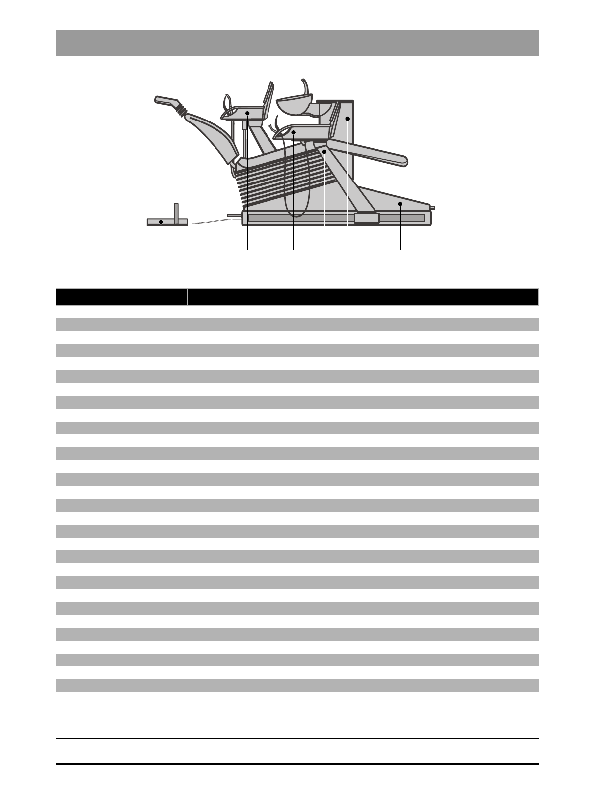
Component PCB / Module
Dentist element (AE) PS = Control panel
AG = Base plate
IR = Flexible PCB
AVL = Supply for lamp C1
AD2 = Camera module
ACI = HF adapter, from C1
HF+ = HF module, from C1
AJ = Control module
AS = SPRAYVIT module
AL = Siromot module
AV = Distributor light module
AH = Solenoid valve and heater module
AU = SIROSON module
AO = HF modulation module, model 96
AC = Output stage for SIROTOM
Support arm (TA) TS = Support arm control
Assistant element (HE) PS = Control panel
AJ = Control module
AS = SPRAYVIT module
IR = Flexible PCB
HG = Base plate
Water unit (WE) WS = Control PCB
Patient chair (ST) SE = Chair output stage
SS = Control ST
NS = Power supply PCB
SA = Connection box control
NM = Monitor power supply
SVC = Video PCB
SL = Wiring PCB
KS = 4-way foot switch
Foot switch (FS) AF = Foot switch plate
1 Overview of modules and PCBs
)RKPMWL
1
STAEHEFS WETA
+
+
+
59 06 610 D 3386
D 3386.077.01.01.02 11.2001
1 - 3
Page 10

1 Overview of modules and PCBs
1 - 4 D 3386.077.01.01.02 11.2001
59 06 610 D 3386
Page 11

C1+
2 Important notes
Page 12
2 Important notes
2.1 Technical data
Model designation C1
Power supply 230V∼ 50Hz,
Nominal current 4.5A at 230V,
+
115V∼ 50/60Hz
9.5A at 115V
2.2 Warnings and safety notes
Caution! Prior to opening the unit, connecting a measuring instrument or replacing parts: Switch the unit OFF.
Operating safety: To guarantee the operating safety, the use of mobile radio telephones in the practice or hospital
area must be prohibited.
Troubleshooting: If you encounter difficulties search in the error catalog first and follow the procedure described
in it.
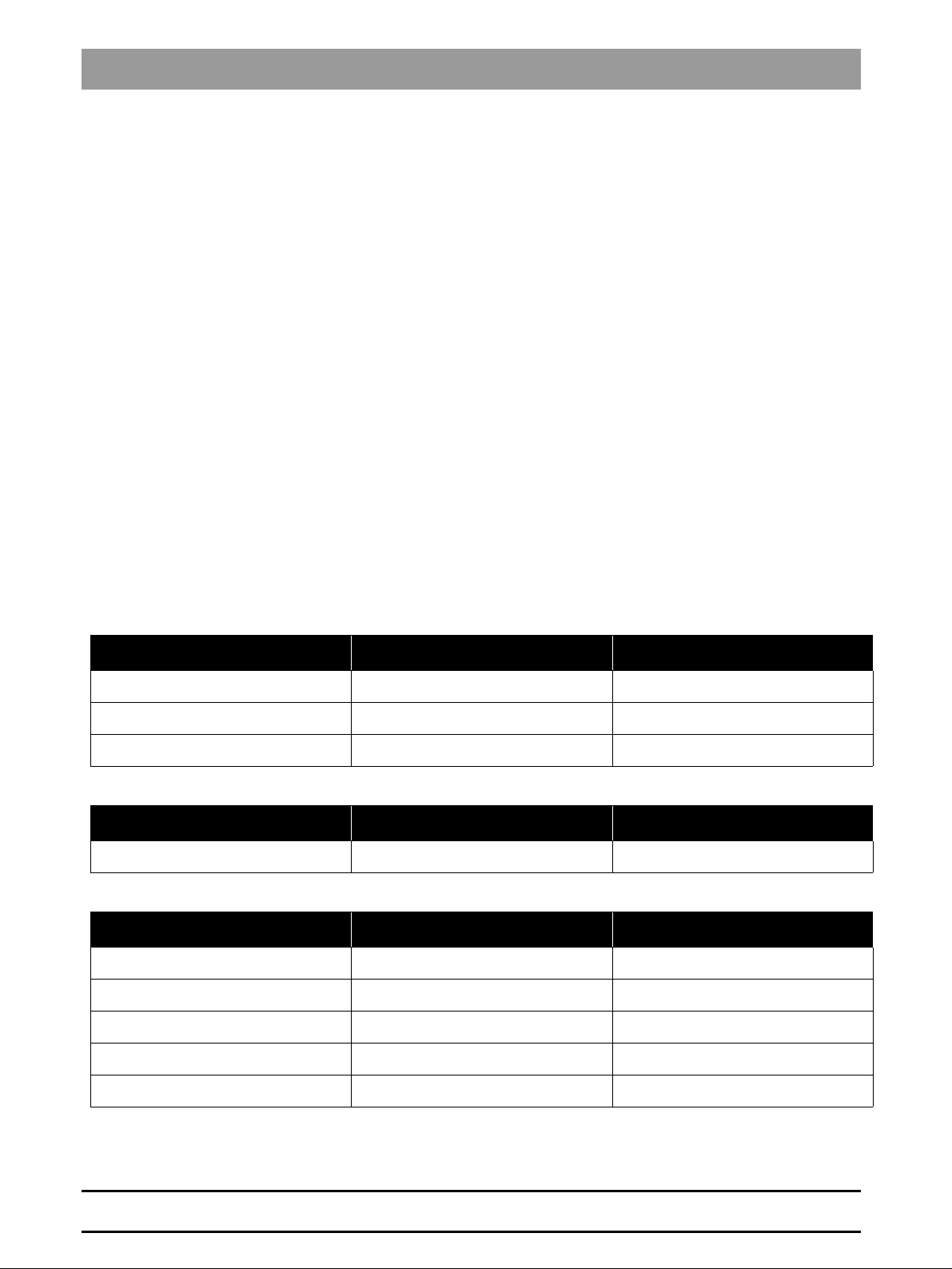
2.3 Minimum configuration
C1 serial no. < 3000
C1 component PCB Software version
Dentist panel / Assistant panel PS / Control panel >= 1.6
Dentist element / Assistant element AJ / Dentist element control >= 1.9
Water unit WS / Water unit control >= 1.9
C1 serial no. > 3000
C1 component PCB Software version
Water unit WS >= 2.1
+
serial no. > 10 000
C1
C1+ component PCB Software version
Dentist panel / Assistant panel PS / Control panel >= 2.3
Dentist element / Assistant element AJ / Dentist element control >= 2.5
Connection box SA / Connection box control >= 3.0
Patient chair SS / Chair control >= 2.5
Water unit WS / Water unit control >= 3.0
2 - 2 D 3386.076.01.01.02 11.2001
59 06 628 D 3386
Page 13
2 Important notes
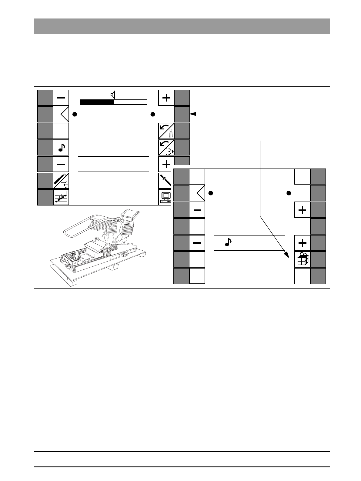
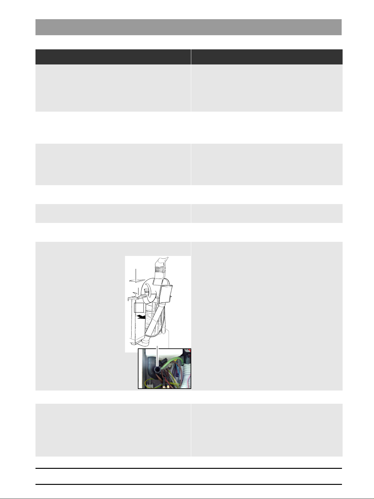
2.4 Packing position for repackaging
To repack the chair (e.g., for transport to a trade fair), move it to the position
shown.
)RKPMWL
Cur
sor
Key
30
TONE
Auto
Ret
ROM
1.
2.
“Invisible” key
“Packing” key
880
2
Vid.
Mod
SAV
59 06 628 D 3386
D 3386.076.01.01.02 11.2001
To do this, press the following keys:
1. “Invisible” key in basic settings dialog 2
2. “Packing position” key
The chair now moves to the packing position automatically.
2 - 3
Page 14

Page 15

C1+
3 Wiring diagrams
Page 16
3 Wiring diagrams
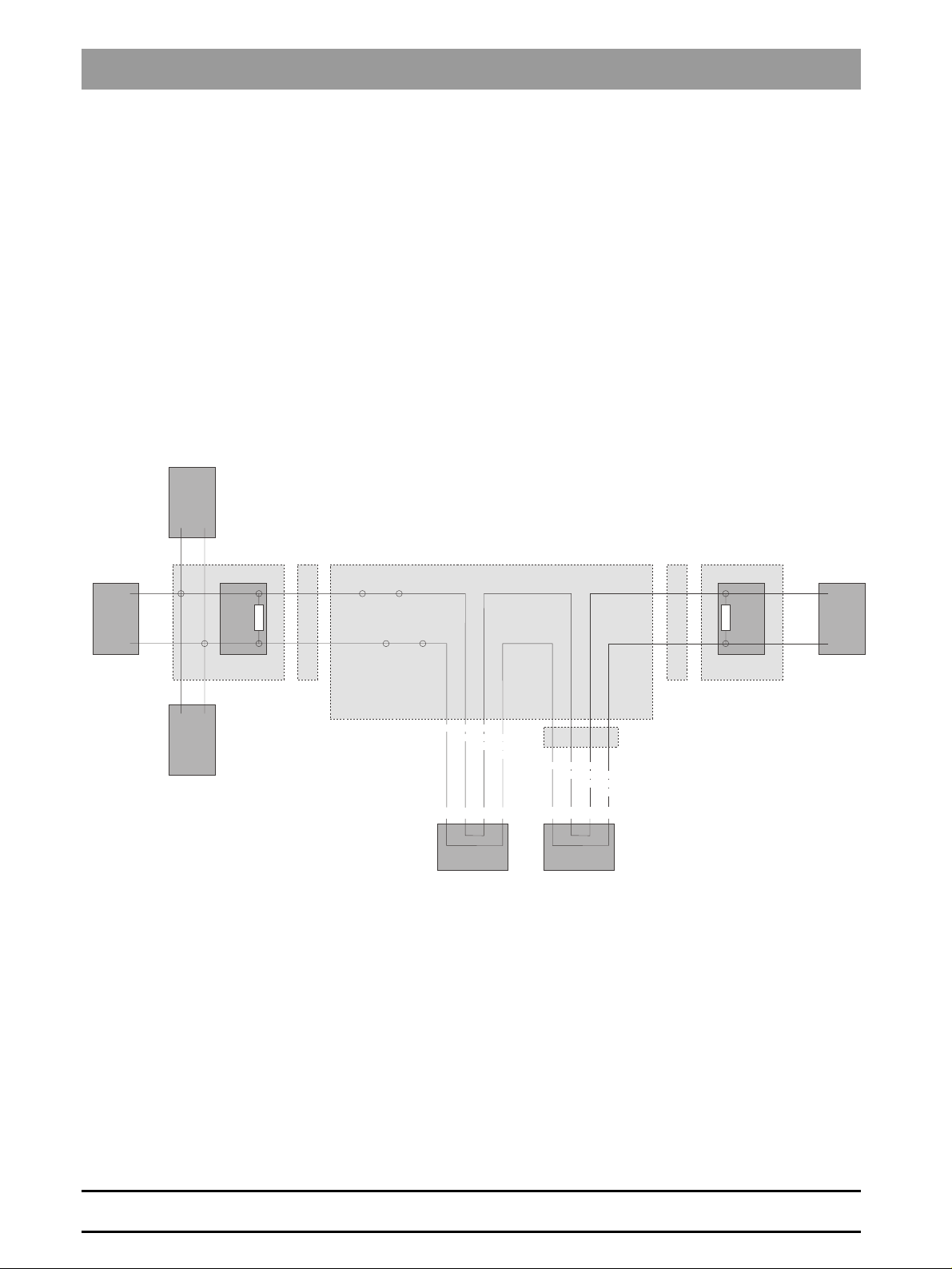
3.1 Wiring diagram of CAN bus
HF+
AP
Connection area
Dentist element
AT
AE
Connection area
GA1 GA2
X1 X2
X1 X1X2X1
1 1A1
1 1
CAN H
CANHHEIN
AK
2 2B1
2 2
Track
X10
12X312
CAN L CAN L HE IN
X4 X3
B1 B1A1 A1A3 A3B3 B3
CAN L ST IN
CANHSTIN
CAN H ST OUT
CAN L ST OUT
25B11AA2A64B
X1 X5
215 6
CAN L ST IN
CANHSTIN
CAN H ST OUT
GA3
CAN L ST OUT
ST WE
A1
B1
Connection area
Track
Connection area
Assistant element
HE
HP
3 – 2 D 3386.076.01.01.02 11.2001
59 06 628 D 3386
Page 17
3 Wiring diagrams
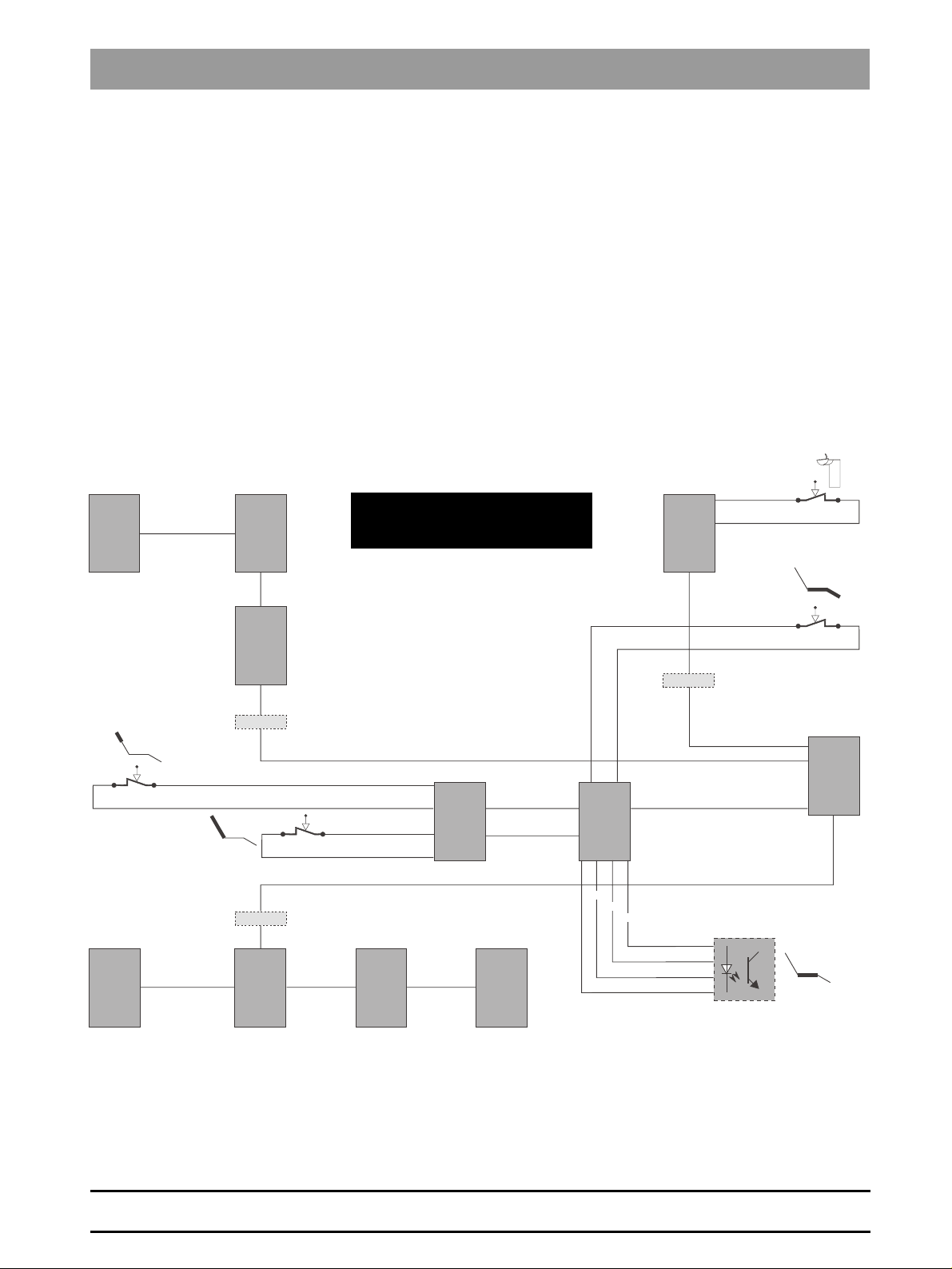
3.2 EMERGENCY STOP wiring diagram
)RKPMWL
3
PS
PCB
TS
PCB
X1.2
S5
X3.4B (C1/A)
X3.2
AJ
PCB
HG
PCB
GA2
GA1
AG
PCB
X1.5B
X4.5B
X1.3
X2.3
X1.3
X1.3
X4.5B X3.2X2.5 X1.5B
S3
The EMERGENCY STOP can be
triggered both by the safety switch
and the software.
X3.3A
X4.B
X4.A
AJ
PCB
X3.3B
X6.2A
X6.1B
SL
PCB
X1.2X2.5A (C1/A)
PS
PCB
X3.B X3.A
SS
PCB
X3.3
X3.2
X3.4
X3.1
WS
PCB
GA3
X5.3A
X3.3
X3.2A
X2.2A
S2
S2
SA
X11.2
X11.3
PCB
X4.2A
X1.2A
A
A
C
E
K
C
V1
E
K
59 06 628 D 3386
D 3386.076.01.01.02 11.2001
3 – 3
Page 18

Page 19

C1+
4 User-defined settings
Page 20

4 User-defined settings
The following user-defined settings must be made after
replacing PCBs or software on the C1.
Component (PCB / software) User-defined settings
Dentist element PCB AJ
Also in case of software upgrade from
version < 1.6 to version >= 1.6
and from version < 2.0 to version >= 2.0
Dentist panel AP Panel-specific settings:
Assistant element PCB AJ
Also in case of software upgrade from
version < 1.6 to version >= 1.6
and from version < 2.0 to version >= 2.0
Instrument settings for all function levels
SPRAYVIT L: Instrument light, water and air temperature
SIRONA motor: Speed, instrument light, direction of rotation, cooling media,
direct starter, foot switch control
Turb ine: Instrument light, cooling media
SIROSON L: Intensity, instrument light
SIROTOM: Cutting current, coagulation current
POLYLUX: Exposure time, soft start (ON / OFF)
Holder assignment for saline solution
(in case of missing Sprayvit light and water heater generate 20 pump strokes)
In case of camera integration: video mode
Brightness, contrast, keyboard sensitivity, audio signal volume,
key clicking tone (ON / OFF), timer settings,
simplified programs (ON/OFF), cursor (ON/OFF)
SIROTOM operating and alarm tone,
preselection of key position for direction of rotation/cooling medium/chip
blower in instrument program.
Sivision / bell switch-over version 1.7 or higher
In case of secondary monitor function, PC dialog (ON/OFF).
Different tones for each row of keys (ON/OFF).
SPRAYVIT L: Instrument light, water and air temperature
POLYLUX: Exposure time
Functionality of the 4-way foot switch for Polylux and suction function version
2.0 or higher
Assistant panel HP Panel-specific settings:
Water unit PCB WS
Also in case of software upgrade
Patient chair PCB SS
Connection box PCB SA
Also in case of software upgrade
Brightness, contrast, keyboard sensitivity, audio signal volume,
key clicking tone (ON / OFF), timer settings,
simplified programs (ON/OFF)
Sivision / bell switch-over version 1.7 or higher
SIROLUX: Brightness, reflector stage, SIROLUX switching condition in
relation to chair position,
tumbler filling quantity, tumbler filling (ON/OFF) when approaching S position,
suction intensity, possibly time and date
Chair positions:
User, user size, treatment position (sitting/standing)
Track positions of dentist element
Cuspidor flushing time, cuspidor flushing (ON/OFF) when approaching
S position,
4-way foot switch functionality (switch-over headrest/backrest),
Type of key for bell or free key (key/switch)
59 06 628 D 3386
4 – 2 D 3386.076.01.01.02 11.2001
Page 21

Component (PCB / software) User-defined settings
4 User-defined settings
Support arm control PCB TS
Also in case of software upgrade
Support arm position excluding track
Intensity of saline solution pump
)RKPMWL
4
59 06 628 D 3386
D 3386.076.01.01.02 11.2001
4 – 3
Page 22

Page 23

C1+
5 Error catalog
Page 24
5 Error catalog
Component
Dentist
element
Dentist
element
Dentist
element
Dentist
element
Dentist
element
Dentist
element
Description
of problem
Loss of instrument
programs.
After removing the
instruments, the
factory settings are
displayed for all levels
and holders.
Sprayvit light switched
off.
Service code
message: AE 7F
Instrument failure
Dentist panel closes
the instrument dialog.
Instrument functions
Motor
Scaler
Turbine
SIROTOM
including media spray,
water and instrument
light are shut off, if
active.
After depositing and
removing again,
normal function.
Instrument failure
Instruments
Motor
Scaler
SIROTOM
do not function when
activated.
Media spray, water
and instrument light
are switched when
activated.
After depositing and
removing again, same
error.
Can only be remedied
by switching on/off.
Instrument failure
SIRONA motor
The instrument Sirona
motor interrupts its
function or does not
function when
activated.
Media spray, water
and instrument light
remain switched on or
are switched when
activated.
After depositing and
removing again,
normal function.
Service code
message: AE 00 6B
Sirona motor runs
on for too long
Scaler switches off
again after 1–2
seconds.
Scaler dialog is
closed.
Cause Corrective action
Software error PCB AJ of
version <2.0
Error while reading hose
coding
following, e.g.,
electromagnetic
interference
or contact problems on
hose coupling.
Software version PCB AJ
in dentist element
<1.8.
Software error on PCB
AJ in dentist element, in
case of very short
instrument removal, e.g.,
due to oscillating motion
of the thin SIROTOM
hose.
Software version PCB AJ
in dentist element
<1.8.
The software of PCB AL
(Siromot module)
detects open motor load
circuits in very smooth
motors.
Software version PCB
AL in dentist element
<3.6.
Software PCB AL in
dentist element <3.7
Water on the flange due
to leaks in hose or
heater.
Residual moisture due to
thermal disinfection
Replace AJ software.
Part No.: 54 33 375
Replace AJ software.
Part No.: 54 33 375
Check and correct (if necessary) the position
of the SIROTOM flange (if available).
Do not overlap or cross the cables.
Replace AJ software.
Part No.: 54 33 375
Replace AL software.
Part No.: 54 33 383
Replace AL software.
Part No.: 54 33 383
Remedy leaks.
Remedy moisture.
5 – 2 D 3386.076.01.01.02 11.2001
59 06 628 D 3386
Page 25
5 Error catalog
Component
Dentist
element
Dentist
element
Dentist
element
Dentist
element
Dentist
element
Dentist
element
Description
of problem
Performance of
scaler is reduced or
fluctuating, or no
performance.
High-frequency
whistling.
Whistling tone from
dentist element
when activating a
bur instrument
Motor/turbine,
immediate cooling/
driving air
After removing the
motor,
turbine
cooling/driving air is
immediately on, or
after releasing the foot
switch cooling/
driving air and spray,
if any, are not
switched off.
After depositing the
instrument everything
is switched off.
Occurs on all
motors/turbines,
possibly only from
time to time
Motor/turbine, low
air outlet.
After removing the
motor,
turbine
or after releasing the
foot switch, low air
outlet. After
depositing the
instrument everything
is switched off.
Does not occur on
exactly one motor/
turbine.
No air and no water
on one bur
instrument.
Dripping
instruments.
Cause Corrective action
Old sealing compound of
piezo is brittle.
Electrical contacts in
handpiece are broken.
Pressure setting too low
MV11
Module
Solenoid valve MV11 is
caught.
Defective membrane in
the module of the
instrument for which the
error does not occur.
MV21-X on module
defective (X – holder no.)
White break on “auto”
valve of module due to
excessive screwing
torque or spring force too
low.
Replace handpiece
Replace membrane and check input pressure, pressure =
4.3 bar +/- 0.1 (in case Sprayvit flow is active)
Replace MV11.
Replace module.
Replace solenoid valve MV11.
Replace membrane and check input pressure.
Pressure = 4.3 bar +/- 0.1
(in case SPRAYVIT flow is active).
Replace MV21.X.
“Auto” valve has been reworked,
replace “auto” valve, do not tighten too hard.
Check filter in heater.
English
5
59 06 628 D 3386
D 3386.076.01.01.02 11.2001
Filter tissue of heater is
dissolved.
Precipitation in the
heater element.
Check filter in heater and replace it, if necessary, and rinse
water pipes.
(Defective filter and information to Bensheim)
Replace heater and rinse water pipes.
5 – 3
Page 26
5 Error catalog
Component
Dentist
element
Dentist
element
Dentist
element
Dentist
element
Dentist
element
Dentist
element
Support
arm
control
Support
arm
control
Description
of problem
No instrument dialog
when removing
instruments.
SPRAYVIT 4000
occasionally without
water.
(Air is still available)
Moist air on
SPRAYVIT.
Some water is ejected
when the air key is
pressed.
SPRAYVIT L
handpiece becomes
hot.
Both heater cartridges
heat up when only one
key is pressed.
Air heater and
SPRAYVIT L heat up
immediately after
removing the
instrument.
Valve body is burnt.
Assistant element
Polylight cannot be
selected using the
dentist panel.
Software PCB AJ
assistant element
version 2.0
Chair and AE travel
to position “0” when
an instrument is
removed.
Cursor is switched off
(M1 mode), panel in
chair program, “FS
down” activated
Dentist element
does not reach
programmed
position.
Program key must be
pressed several times.
Service code
message in AT/HP:
40 04
(RESET AT) –
frequent in C1/96).
Support arm does
not swivel in joint 1,
Motor 1 is running
(Serial no.: <3000)
Cause Corrective action
Instrument in holder 5 or
6 has not been deposited
properly.
Instrument tray bent
(holder is not aligned
with light barrier)
Transparency of ZEG
hose
Contact problem or
humidity on base of air
heater in valve body.
Consequence:
SPRAYVIT is not
detected by dentist
element.
Damaged o-rings on
Sprayvit nozzle, due to
sterilization and lack of
maintenance.
Water in SPRAYVIT
hose.
Software error in PCB AJ
version 2.0
Software error dentist
panel / assistant panel
PCB TS reset because
watchdog tolerance is
too high.
PCB TS:
Serial no. >3000:
Hardware <2.1, Software
<1.5
Serial no. <3000:
Hardware <1.3
Pertinax pinion of joint 1
defective
Slipping clutch of joint 1
skids
Information for the customer.
Install a new instrument tray
Hose change in progress
Temporary measure:
Clean air heater (remove also solder residue) and tighten
contact terminals.
Replace o-rings on Sprayvit nozzle.
Replace hose and replace valve body, if necessary.
Replace AJ software.
Part No.: 54 33 375
No solution as of yet.
Serial no. <3000:
Software version on PCB PS >= 1.8
Serial no. >3000:
Software version on PCB PS >= 1.7
Replacement of PCB TS.
Part No.: 46 96 931 - Serial no. >3000
Part No.: 46 85 231 - Serial no. <3000
Install new motor 1 with metal pinion
Replace slipping clutch of joint 1
5 – 4 D 3386.076.01.01.02 11.2001
59 06 628 D 3386
Page 27
5 Error catalog
Component
Support
arm
control
Support
arm
control
Support
arm
control
Support
arm
control
Support
arm
control
Description
of problem
Support arm does
not swivel in joint 1,
Motor 1 is running
Furthermore, a
knocking noise can be
heard (serial no.:
>3000).
Support arm motors
run on.
Support arm motors
keep running for a few
seconds after
reaching the
programmed position.
Support arm motor 1
does not reach
programmed
position.
Program key must be
pressed twice
Unit head drops
when an additional
load is applied.
The unit head keeps
falling back to the
lowest position.
Cause Corrective action
Gear Z70 is damaged,
because motor 1 has not
been inserted deep
enough or grub screw is
missing in lower support
arm bearing.
Pot. target value is
outside the movement
range
Slipping clutch of joint 1
has not been tightened
enough at factory
Only serial no.: >3000
Slipping clutch of joint 1
too weak only serial no.:
<3000
Spring weight
compensation not
properly set.
Slipping clutch torn off.
Replace lower support arm bearing entirely. Rep. no.
5433623
Check the fastening and fitting of the potentiometers, then
try to travel to the corresponding program positions again
and press the save key.
Tighten slipping clutch with a screwdriver, as necessary.
Factory setting: 20 +- 5N
Replace slipping clutch of joint 1.
Installation instructions currently being drafted
Tighten the spring using allen screw on spring arm.
Remarks: The slipping clutch of the height adjustment is
exclusively required to dampen the spring force. It is preset
at the factory and can be adjusted slightly in exceptional
cases. Generally, the following applies: Always tighten the
spring for weight - force adjustment.
Dismount the slipping clutch.
When the driving pin is not hammered in deep enough,
drive it in and then mount back the slipping clutch with an
undamaged groove.
English
5
Support
arm
control
Assistant
element
Assistant
element
Unit head does not
swivel, motor is
running.
Polylight cannot be
started.
After removing the
instrument the timer in
the assistant panel
does not switch over
to the Polylight values
and the Polylight
cannot be started.
Polylight light power
is not in green range
when measured with
Translux Test.
Slipping clutch has burst
due to excessive
tightening
The grub screw used to
attach the pinion to the
back-geared motor 3 is
loose.
Software error PCB AJ
software, assistant
element.
Polylight detection in
case of an old Polylight
(without electronics)
using fan current
defective.
Software version on PCB
AJ,
Assistant element <1.9.
Fiber optic is not properly
inserted or locked in
place in the module.
Lamp has air leaks so
that the quartz tube has
become opaque.
Lamp has not been
inserted properly.
Dirt in filter of lamp
module, at light entrance
or exit of fiber optic and
of handpiece.
Replace slipping clutch. Rep. no. 3319501
Tighten the grub screw and secure with Loctite.
(The back-geared motor must be dismounted to do this)
Replace AJ software (basic retrofit kit).
Pull out the fiber optic and insert it again, until it catches.
Replace the halogen lamp. Only use selected Osram
Xenophot HLX bulbs.
Lamp must lie flat against the heat sink, place the lug on
the lamp in the notch intended for this purpose.
Clean all interfaces with ethanol
59 06 628 D 3386
D 3386.076.01.01.02 11.2001
5 – 5
Page 28
5 Error catalog
Component
Assistant
element
Water
unit
Water
unit
Water
unit
Water
unit
Water
unit
Water
unit
Description
of problem
Short total failure.
SIROLUX (unit
model), film viewers, if
any, are shut off and
must be switched on
again.
The suction and
separator function are
interrupted for 2–4
seconds and start up
by themselves again.
Service code
message in AP/HP:
40 08
Amalgam separator
full message too
early.
Panel display
amalgam and
continuous tone,
rotor not filled yet
(total weight of rotor
<500 g)
Amalgam separator
goes over to fault
mode, loud noises
and vibration from
amalgam separator.
Amalgam is flashing
and intermittent
beeping tone.
Service code
message: WE 06
Amalgam separator
goes over to fault
mode.
Amalgam is flashing
and intermittent
beeping tone.
(loud drive noise,
rustling or standstill)
Service code WE: 5C
Drive below target
speed
There is barely any
water arriving to the
tumbler filling.
Tumbler filling does
not work from time
to time.
Vibrations of the
amalgam separator
Cause Corrective action
Software error on PCB
WS, which can lead to a
RESET of the module
when filling the water
tank and the disinfectant
injection.
Serial no. <3000:
Software version on PCB
WS <1.9.
Serial no. >3000:
Software version on PCB
WS <2.1.
Software version on PCB
WS <2.0.
Driver bolt defective.
Bearing damage on
motor (audible) due to
leak in pump
Motor is blocking
Bearing in lower part is
defective
Rotor axle is defective
Drain is blocked up
Suction from lower part
is blocked up
Media pipe is clogged
due to precipitation in the
heater element.
Software version on PCB
WS <2.4.
Float switch in mixing
tank is caught.
Amalgam separator has
been mounted stressed
Replace AJ software.
Part No.: 54 33 391
Replace WS software.
Part No.: 54 33 391
Replace amalgam drive.
Replace amalgam drive.
Replace the amalgam drive.
Check the rotor’s operation (must run smoothly)
replace lower part, if necessary.
Replace rotor
Check siphon and drain, clean them if necessary.
Check the hose path
Clean suction channel in lower part of amalgam separator.
Replace heater,
clean media pipes, if necessary.
A solution is being worked out.
Replace float switch.
Position all connections to amalgam separator so as to
leave 1mm clearance in all directions from amalgam
separator,
Defective rotor or
flyweight
Suction from lower part
is blocked up
Transport safety device
has not been removed.
Replace rotor
Clean suction channel
Remove the transport safety device
59 06 628 D 3386
5 – 6 D 3386.076.01.01.02 11.2001
Page 29
5 Error catalog
Component
Water
unit
Water
unit
Water
unit
Water
unit
Water
unit
Water
unit
Water
unit
Description
of problem
Tumbler falls into
cuspidor
Cuspidor does not
drain off
intermittent beeping
tone
Service code WE: 07
Water escapes from
water unit
Suction does not
switch off or is
delayed
Water unit is
deformed in lefthanded version
Disinfectant
consumption too
high
Flushing water
quantity:
too low
too high
Cause Corrective action
Slope of cuspidor too
steep
Vibrations of the
amalgam separator
Clogged drain, def. water
detector, air pressure too
low
Leaks on tumbler plug
adapter
Water escapes from
mixing tank overflow,
Clogged or badly
positioned drain
MV 33 is caught Replace MV 33
Lack of stiffness in lefthanded version
Metering valve is leaking Replace the metering valve
Control nozzle not
properly adjusted
C
B
1.
2.
Reduce slope of cuspidor, if possible
Order silicone mat free of charge
Part No.: 54 46.443
Use of tumblers with hollow bottom
See: Vibrations of the amalgam separator
Check drain and air pressure;
Clean water detector or replace, if necessary;
If everything is in order, reduce the flow of the cuspidor
flushing
Replace sealing ring in plug adapter
Part No.: 70 36 189 (red o-rings)
Check slope of drain,
Clean the siphon
Retrofit reinforcing plate
Part No.: 47 08 272
Part No.: 14 35.580
1. Adjusting cuspidor flushing:
For right-handed version – Remove side panel A of water
unit and adjust control nozzle B until the bottom of the
cuspidor is flushed evenly. Remount back side panel A of
water unit.
For left-handed version – Remove cover C. Lift rubber
cover and adjust control nozzle B using a coin until the
bottom of the cuspidor is flushed evenly. Refit the cover.
2. Check the swivel-back motion of the cuspidor:
English
5
Patient
chair
Patient
chair
59 06 628 D 3386
D 3386.076.01.01.02 11.2001
Leaks in connection
box
No chair motion after
switching on.
Serial no.: <3000
Chair output stage
version: Hardware
PCB SE 1.0
Service code
message: ST 03 37
(also 01 01)
A
B
1.
Counter nut on ceramic
valve is loose
Output stage relay is
caught.
– Swivel the cuspidor into the movement range of the
chair
– Press the manual chair button and start the chair
program consecutively
The cuspidor must always swivel back into the starting
position automatically
Tighten the nut, fix by a lock nut and secure with locking
varnish
Replace PCB SE - Version 1.1.
5 – 7
Page 30
5 Error catalog
Component
Patient
chair
Patient
chair
Patient
chair
Patient
chair
Description
of problem
No chair motion after
switching on
only in cooled
treatment center
Service code
message: ST 02 00
to 02 05
Chair does not reach
programmed
position.
Program key must be
pressed several times,
particularly when
travelling to S or 0
position.
No service code
message in ST.
Software PCB SS
<1.8.
Chair does not reach
programmed
position.
Program key must be
pressed several times,
or chair does not
leave position.
EMERGENCY STOP
relay is switching.
Service code
message in AP/HP:
40 04
(RESET AT)
No service code
message in ST.
(more frequent for
serial no.: >3000)
Chair does not reach
programmed
position. Service
code message: 08
0X; X = 0...2
Cause Corrective action
Temperature sensibility
of PCB SS,
Software version on PCB
SS <2.0
EMERGENCY STOP
activated by
EMERGENCY STOP
sensory mechanism.
Defective or badly
adjusted safety switch
for foot part, or defective
cable.
Service code ST 09 11,
EMERGENCY STOP
activated by safety
switch for foot part.
Defective safety switch
for backrest, or defective
cable or backrest
mechanics jammed.
Service code ST 09 13,
EMERGENCY STOP
activated by free lift
switch of backrest.
PCB TS is RESET due to
excessively high
watchdog tolerance.
PCB TS:
C1/96, Serial no. >3000:
Hardware: <2.1,
software: <1.5
C1/A: Serial no. <3000:
Hardware: <1.3
Broken wire in the motor
sensor circuit (L16)
Serial no. <3000.
Contacts pushed back
on connector X15
on motor circuit (L16).
Replace the software on PCB SS
Replace software for diagnostics
PCB SS, version >= 2.0 to recognize source of
EMERGENCY STOP.
Serial no.: <3000, Part No.: 54 33 680
Serial no.: >3000, Part No.: 54 33 409
Adjust or replace the switch or cable.
(Switch must only switch shortly before the upper end stop
and must not be charged in the lower end stop).
Replace the switch or cable.
Eliminate the stiffness of the backrest.
Replace PCB TS.
Serial no.: >3000, Part No.: 46 96 931
Serial no.: <3000, Part No.: 46 85 231
Replace motor sensor circuit (L16).
Check contacts.
Patient
chair
Patient
chair
Chair does not reach
programmed
position. Service
code message: 08 03
Chair does not travel
to programmed
position.
Potentiometer 0–2
defective.
Potentiometer 3 no
longer moves into gear
due to worn sword rollers
Unintentional call of the
factory programs, mostly
with foot switch.
(Display with icon in
odontogram)
Switch the potentiometers between each other and check if
error is reproduced,
replace the potentiometer, if necessary
Install roller kit
Part No.: 54 33 870
Information to customers.
59 06 628 D 3386
5 – 8 D 3386.076.01.01.02 11.2001
Page 31

5 Error catalog
Component
Patient
chair
Patient
chair
Patient
chair
Patient
chair
Patient
chair
Description
of problem
Chair keeps
travelling when key
is released on the
panel.
Does not occur with
operation using foot
switch.
Chair does not travel
to zero position.
Chair does not
budge.
0 key on panel is not
active
(gray without frame).
Chair starts
travelling
uncontrollably
If the chair is moved to
a treatment position
from the zero position
using the HP, the AP
remains in the zero
position dialog. After
removing and
depositing an
instrument, the AP
remains in the zero
position dialog. In this
situation, the forward
foot switch starts the
movement to the
starting position.
Programmed 4-way
foot switch
assignment (tilting
part / backrest) is
lost after switching
off (serial no. <3000)
Chair drives are
getting louder
Cause Corrective action
Keyboard sensitivity in
dentist/assistant panel
set too high.
Not all instruments in
dentist element are
recognized as deposited.
Software error in panel
Serial no. <3000:
Software version on PCB
PS <1.8
Serial no. >3000:
Software version on PCB
PS <1.7
Software error PCB
SA1.3
the hardware settings on
X12 are reused after
switching on
Lack of lubrication
between spindle and
spindle nut
Adjust the keyboard sensitivity in the service dialog of the
panel (value must be greater).
If this is not successful, please contact DCC Bensheim.
Deposit instruments properly.
If a stylized instrument appears in the chair program dialog
under the inactive 0 key, go to the instrument dialog and
deposit the corresponding instrument.
If no stylized instrument is displayed, then check the
SPRAYVIT light barrier.
Serial number <3000:
Software version on PCB PS >= 1.8
(Part No. 54 33 474)
Serial number >3000:
Software version on PCB PS >= 1.7
(Part No. 54 33 482)
Set 4-way foot switch assignment on X12,
Jumper X12.1-4 set:
Movement of back rest,
Jumper not set:
Tilting part motion
Lubricate the spindle with grease 622
Part No. 18 73 947 Chesterton
English
5
Patient
chair
Patient
chair
Dentist
panel
Assistant
panel
59 06 628 D 3386
D 3386.076.01.01.02 11.2001
Backrest squeaks
when travelling or
starting.
Noises on the
dentist element
track.
The key on the panel
gets stuck.
Chair drive defective
Slip-in guides. Do not lubricate!
Uneven ground.
Axle of the deflection roll.
Belt tension too weak
Sensitivity setting or
temperature sensitivity of
the piezo keys.
Replace chair drive
Adjust the slip-in guides with a clearance of about 0.2mm,
or replace slip-in guides.
Install compensation disks.
Lubricate or replace the deflection axle, if necessary.
Check belt tension and adjust, if necessary.
Set the keyboard sensitivity in the service dialog of the
panel (value must be greater).
If this is not successful, contact DCC Bensheim.
5 – 9
Page 32

5 Error catalog
Component
Dentist
panel
Assistant
panel
SIROLUX Sirolux switches off
SIROLUX SIROLUX switches
SIROLUX Glass tube cannot
Description
of problem
Panel switches to
reduced user dialog
by itself.
If the foot switch is
turned to the right
after removing an
instrument at the time
the display changes,
the key for the manual
chair dialog remains
active in the reduced
or non-reduced
instrument dialog until
the changeover is
made.
for a few minutes.
Switching of thermal
switch due to
overheating.
off immediately after
having been
switched on.
be fitted
Serial no. 6000–7569
Cause Corrective action
Software error on PCB
PS
Serial no. <3000:
Software version on PCB
PS <1.6
Serial no. >3000:
Software version on PCB
PS <1.5
Software version WS
<2.0
The temperature guard
responds too early
Maladjustment of the
heat protection
Lamp too deep in the
thermal shield
Circuitry goes over to
current limitation and
switches off.
Software version
installed on PCB WS 2.2.
Tolerance problems Replace glass tube
Serial number <3000:
Software version on PCB PS >= 1.8
Serial no. >3000:
Software version on PCB PS >= 1.7
Update software WS, (or reduce reflector factor to max. 4)
Check the color of the supply cable of the temperature
guard (recognizable after removing the handpiece). If it is
yellow, replace the temperature guard (new: supply cable
orange) Part No.: 47 08 108
Adjust the heat protection
(instructions see list of spare parts)
Check focus
(see Operating Instructions)
Replace WS software.
Part No.: 54 33 391
Part No.: 51 72 494
5 – 10 D 3386.076.01.01.02 11.2001
59 06 628 D 3386
Page 33

C1+
6 Reading service codes
Page 34

6 Reading service codes
BAR
BAR
50
50
PSI
PSI
BAR
BAR
50
50
PSI
PSI
50
50
PSI
PSI
PSI
PSI
PSI
PSI
50
50
PSI
PSI
50
50
PSI
PSI
50
50
PSI
PSI
Now, actuate all functions of the treatment center once:
- All instruments (removal and start)
- Both chair programs
- Cuspidor flushing and tumbler filling
- Remove ejector
6.1 Reading the service codes on the dentist
panel
CAUTION!
Prior to starting troubleshooting the C1 treatment center must be switched OFF and back ON again.
If the malfunction is known,
it must be activated.
For example: malfunction > no suction.
Switch C1 OFF and back ON. > Activate suction.
Press program change
to service
program
S
Om
Start
San.
30s
08:01
I
I
BARBAR
S
S
P
P
5
5
0
0
Press service
information
Ident
08:01
Press
program change
5
5
R
R
I
I
0
0
S
S
P
P
BA
BA
R
R
I
I
S
S
P
P
BA
BA
Press program
change to assistant
program
S 0
5
5
0
0
12
34
56
P
08:00
Browse
I
I
S
S
BARBAR
P
P
5
5
0
0
Back to
I
I
BARBAR
S
S
P
P
5
5
0
0
previous
program
21
Set
Up
Continuous cou nter
from 1–256
I
I
S
S
P
P
BARBAR
Day
50
1
5.
7.
00
30
03
2
5.
7.
3
5.
7.
4
0.
0.
5
4.
7.
6
4.
7.
0
00
0C
07
0
00
01
0
00
00
00
0
00
1A
0
00
1C
1D
0
Month
Service codes
08:00
Browse
I
I
S
S
BARBAR
P
P
5
5
0
0
Change
50
SI
SI
P
P
BARBAR
to another
node
Zero line
Repetition counter
6 – 2 D 3386.076.01.01.02 11.2001
59 06 628 D 3386
Page 35

Only the service codes above the zero line must be taken into account for
troubleshooting. The most up-to-date service code can be found in line 1.
6 Reading service codes
< Service - Info >
Node AP
If the zero line is in line 1, the queried node
(PCB) is in order electrically.
If there are service codes above the zero line, these must be analyzed as
follows:
A Evaluate the service code above the zero line (line 3 in this example).
The service code for this node (AP) can be found in the numbers between
both vertical lines (01 in this example).
i
NOTE
If the vertical lines do not appear, the minimum configuration is not available (see
chapter 2, section 2.3). In this case, refer to the service code list of the corresponding
node. In the beginning of this list there is a reference to the column where you will find the
service code!
< Service - Info >
Node AP
< Service - Info >
Node AP
Zero line
Zero line
Zero line
English
6
B Take the corrective action for service code 01 (error_high) from the
service code list.
An “H” after the service code indicates a hexadecimal number and should
be disregarded.
C Evaluate the second service code above the zero line (in line 2 in this
example, 0C 07).
D Take the measure for service code 0C (error_high) 07 (error_low) from
the service code list.
E Evaluate all additional service codes above the zero line
as described in A–D.
F Check and evaluate all other nodes in the same way.
G Once the error has been eliminated successfully, switch the unit OFF and
back ON.
H Actuate all the functions of the treatment center once:
- All instruments (removal and start)
- Both chair programs
- Cuspidor flushing and tumbler filling
- Remove ejector
I When the service codes are queried in all nodes, the zero line must
appear as line 1.
59 06 628 D 3386
D 3386.076.01.01.02 11.2001
< Service - Info >
Node AP
Zero line
< Service - Info >
Node AP
Zero line
6 – 3
Page 36

6 Reading service codes
6.2 Reading service codes
with PC connection to C1
Service
Serial
no.
codes
1
0
2
5
3
48
4
1.
+
020100
010100
1
2
3
4
Date
48
Number
0
3
0
020100
5
010100
0
3
Program: Hyperterminal
Settings
Bits per second:
Stop bit: 1
Data bits: 8
Parity: none
Protocol: none
1. Connect the PC to C1+ using the serial interface.
2. Once the terminal program (e.g., Hyperterminal) has been started,
press the ENTER key
to cause the connection box to send the service codes to the
notebook.
Only implemented for SA software > 3.0!
9 600
6 – 4 D 3386.076.01.01.02 11.2001
59 06 628 D 3386
Page 37

C1+
7 Service code listings
Page 38

7 Service code listings
7.1 Abbreviations / service code listings
ADC
AE Dentist element
AG Dentist element system board
AJ
AK Connection box
AL Siromot module
AO HF modulation module
AP Dentist panel
AS Dentist element support arm
AT Sprayvit module
CAN Controlled Area Network
EEPROM Electrically Erasable Programmable Read Only Memory
EPROM Erasable Programmable Read Only Memory
PCB Printed Circuit Board
FS Foot switch
HE Assistant element
HF High frequency
HG Assistant element system board
HP Assistant panel
HW Hardware
KL Holder
LCD Liquid Crystal Display
LED Light Emitting Diode
M Motor
Med_GV Medizinische Geräteverordnung (Directive for medical devices)
MV Solenoid valve
NA Emergency Stop
NS Power supply control module
Pot. Potentiometer
RAM Random Access Memory
ROM Read Only Memory
SA Connection box control module
SE Chair output stage
SS Chair control module
ST Chair
SW Software
TS Support arm control module
U Voltage
US Ultrasound
WE Water unit
WS Water unit control module
Analog-Digital Converter
Dentist element control module
7 – 2 D 3386.076.01.01.02 11.2001
59 06 628 D 3386
Page 39

7 Service code listings
7.2 Service code of PCB (SA) in connection box AK
7.2.1 SW version: 2.0 - 3.0
The service code (error_high) can be found in column 5 of the panel display.
(error_low) xx: disregard
error_
high
0h xx Zero error line For analysis purposes only
1h xx Wrong reference voltage ! Replace PCB SA
2h xx At least one of the four input circuits of the foot
3h xx At least one of the four input circuits of the 4-way
4h xx EMERGENCY STOP test failed (activation of
5h xx PIO fault detected ! Replace PCB SA
6h xx Software cannot be executed on PCB Use compatible software! Inform Hotline
7h xx Relay PCB not recognized by PCB SA ? Relay PCB is missing or open circuit between PCB SA (X18.B3)
8h xx Cannot write to CAN RAM ! Replace PCB SA
9h xx CAN communication impossible/faulty, BUS OFF
0Ah xx Input circuit of service key defective according to
0Bh xx Input circuit of power supply fan defective
0Ch xx Tmax input circuit defective according to self-test No action required, service information only
0Dh xx Overload input circuit defective according to self-
0Eh xx Power fail input circuit defective according to self-
0Fh xx Input circuit of foot switch identification defective
10h xx When writing to EEPROM no acknowledgement is
11h xx Cannot write/write properly to EEPROM ! Replace PCB SA
12h xx Comparison of RAM with mirrored RAM (in
13h xx EEPROM buffer capacity overflow ! Replace PCB SA
14h xx Read timeout on serial interface No action required, service information only
15h xx Write timeout on serial interface No action required, service information only
16h xx ADC BUSY signal authorized active time
17h xx No potential variation on burr during self-test,
18h xx No potential variation on burr during self-test,
19h xx Unused service code
1Ah xx 8V supply voltage outside tolerance
1Bh xx 12V supply voltage outside tolerance
error_
low
Description of service code Corrective action (engineer)
switch is defective according to self-test
foot switch is defective according to self-test
EMERGENCY STOP could not be verified)
condition has been detected
If error persists: CAN module defective, CAN
wiring defective
self-test
according to self-test
test
test
according to self-test
received after authorized writing time
EEPROM) defective, EEPROM read/write error
exceeded, ADC defective
external error in foot switch potentiometer circuit,
ground contact.
external error in AE potentiometer circuit
Power supply failure, short-circuit, blown fuse,
connector
Power supply failure, short-circuit, blown fuse,
connector
! Check all 4 input circuits of the foot switch (SA, X6.A1 to X6.A4
against X6.A5). 5V present on all of them?
NO: Unplug connector X6.
OK Examine/repair foot switch and cable
NO: Replace PCB SA
! Check all 4 input circuits of the 4-way foot switch (X12.2; X12.5;
X12.6 and X12.7 against X12.3). 5V present on all of them?
NO: Unplug connector X12.
OK: Check 4-way foot switch and cable
NO: Replace PCB SA
! Replace PCB SA
and relay PCB (X1.3B)?
NO: Replace PCB SA
? Error occurs only once: Fault exists
NO: Query using Ident dialog: All nodes available?
YES: Replace PCB SA
NO: Open circuit, see CAN wiring diagram
! Replace PCB SA
No action required, service information only
No action required, service information only
No action required, service information only
! Replace PCB SA
! Replace PCB SA
! Replace PCB SA
! Replace PCB SA
! Check foot switch potentiometer circuit
NO: Replace PCB SA
Check AE travel track potentiometer circuit
NO: Replace PCB SA
! Check fuse F6 on NS
! Check 8V circuit SA X5.2 -> NS X2.2
No action required, service information only
)RKPMWL
59 06 628 D 3386
D 3386.076.01.01.02 11.2001
7 – 3
Page 40

7 Service code listings
error_
high
1Ch xx 16V supply voltage outside tolerance
1Dh xx 24V supply voltage outside tolerance
1Eh xx 32V supply voltage outside tolerance
1Fh xx 48V supply voltage outside tolerance
20h xx Overload condition detected For information only. Output stage power of chair is reduced
21h xx Power fail detected in power supply No action required, service information only
22h xx Temperature exceeded in AK power supply (Tmax) No action required, service information only
23h xx Unknown service command will be ignored Incompatible service command in system or in link to diagnostics
24h xx Service command will be ignored, incorrect
25h xx For version 1.x only No action required, inform Hotline!
26h xx 8V supply voltage below tolerance,
27h xx Unused service code
28h xx MV35 current limiting active. External short-circuit ! Unplug connector X14
29h xx Output circuit of cuspidor flushing valve signal
2Ah xx MV35 current too low. External open circuit. ! Activate cuspidor flushing; measure voltage between SA X14.1
2Bh xx Unused service code
2Ch xx Magnetic coupling travel track AT, current limiting
2Dh xx Output circuit of magnetic coupling travel track AT
2Eh xx Magnetic coupling travel track AT, current too low
2Fh xx Unused service code
30h xx Suction pump relay, current limiting active. Short-
31h xx Output circuit of relay suction pump signal
32h xx Relay suction pump, current too low.
33h xx Unused service code
error_
low
Description of service code Corrective action (engineer)
Power supply failure, short-circuit, blown fuse,
connector
Power supply failure, short-circuit, blown fuse,
connector
Power supply failure, short-circuit, blown fuse,
connector
Power supply failure, short-circuit, blown fuse,
connector
parameter
Power supply failure, short-circuit, blown fuse,
connector
(MV35) defective
I_load required: =0,
Actual: >0
active.
External short-circuit
signal defective
I_load required: =0,
Actual: >0
External open circuit.
circuit:
Connector pins, contacts fused, coil defective
defective
I_load required: =0,
Actual: >0
Open circuit.
! Check fuse F7 on NS
! Check 16V circuit SA X5.3 -> NS X2.3
! Check fuse F8 on NS
! Check 24V circuit SA X5.4 -> NS X2.4
! Check fuse F9 on NS
! Check 32V circuit SA X5.5 -> NS X2.5
! Check fuse F10 on NS
! Check 48V circuit SA X5.6 -> NS X2.6
automatically
system. Inform Hotline!
Incompatible service command in system or in link to diagnostics
system. Inform Hotline!
! Check fuse F6 on NS
! Check 8V circuit SA X5.2 -> NS X2.2
? Error persists when cuspidor flushing is activated
YES: Replace PCB SA
NO: Check circuit SA X14.1 -> X14.2 MV35
? Cuspidor flushing active without key activation
YES: Replace PCB SA
NO: Check circuit SA X14.1 -> X14.2 MV35
and X14.2
? U = 24V: Check circuit MV35
? U = 0V: Replace PCB SA
! Unplug connector X19
? Error persists when the coupling is activated
YES: Replace PCB SA
NO: Check circuit SA X19.4 -> X19.5 magnetic coupling
? Coupling active without key activation
YES: Replace PCB SA
NO: Check circuit SA X19.4 -> X19.5 magnetic coupling
! Activate coupling; measure voltage between CBC X19.4 and
X19.5
? U = 24V: Check magnetic coupling circuit
? U = 0V: Replace PCB SA
! Unplug connector X18 on PCB SA
? Error occurs when the relay is activated
YES: Replace PCB SA
NO: Re-insert X18 and unplug connector X1 on relay PCB
? Error persists when the relay is activated
YES: Wiring defective NO: Relay PCB defective
? Relay active without key activation
YES: Replace PCB SA
NO: Check circuit SA X18.A1 -> X18.A4 relay suction pump
! Activate relay; measure voltage between SA X18.A1 and
X18.A4
? U = 24V: Check circuit between SA X18.A1 and X18.A4
? U = 0V: Replace PCB SA
7 – 4 D 3386.076.01.01.02 11.2001
59 06 628 D 3386
Page 41

7 Service code listings
error_
high
34h xx Free relay current limiting active.
35h xx Output circuit of free relay signal defective
36h xx Free relay current too low. Open circuit. ! Activate relay; measure voltage between SAX18.A1 and X18.A2
37h xx Unused service code
38h xx Bell relay current limiting active. Short-circuit:
39h xx Output circuit of bell relay signal defective
3Ah xx Bell relay current too low.
3Bh xx Unused service code
3Ch xx Ozone fan (1) driver circuit, current limiting active.
3Dh xx Output circuit of ozone fan signal defective
3Eh xx Ozone fan (1) driver circuit, current too low.
3Fh xx Unused service code
40h xx Output signal RESERVE1 is not used No action required, service information only
41h xx Output signal RESERVE1 is not used No action required, service information only
42h xx Output signal RESERVE1 is not used No action required, service information only
43h xx Unused service code
44h xx VB direction relay, current limiting active. Short-
45h xx Output circuit of VB direction relay signal defective
46h xx VB direction relay driver, current too low
47h xx Unused service code
48h xx MV56 (ozone) driver current limiting active.
49h xx Output circuit of MV56 signal defective
4Ah xx MV56 driver current too low.
4Bh xx Unused service code
error_
low
Description of service code Corrective action (engineer)
Short-circuit: Connector pins, contacts fused, coil
defective
I_load required: =0,
Actual: >0
Connector pins, contacts fused, coil defective
I_load required: =0,
Actual: >0
Open circuit.
External short-circuit
I_load required: =0,
Actual: >0
External open circuit.
circuit: Relay contacts fused, coil defective
I_load required: =0,
Actual: >0
Open circuit.
External short-circuit
I_load required: =0,
Actual: >0
External open circuit.
! Unplug connector X18 on PCB SA
? Error occurs when the relay is activated
YES: Replace PCB SA
NO: Re-insert X18 and unplug connector X1 on relay PCB
? Error persists when the relay is activated
YES: Wiring defective NO: Relay PCB defective
? Relay active without key activation
YES: Replace PCB SA
NO: Check circuit SA X18.A1 -> X18.A2 free relay
? U = 24V: Check circuit between SA X18.A1 and X18.A2
? U = 0V: Replace PCB SA
! Unplug connector X18 on PCB SA
? Error occurs when the relay is activated
YES: Replace PCB SA
NO: Re-insert X18 and unplug connector X1 on relay PCB
? Error persists when the relay is activated
YES: Wiring defective
NO: Relay PCB defective
? Relay active without key activation
YES: Replace PCB SA
NO: Check circuit SA X18.A1 -> X18.A3 bell relay
! Activate relay; measure voltage between SA X18.A1 and
X18.A3
? U = 24V: Check circuit between SA X18.A1 and X18.A3
? U = 0V: Replace PCB SA
! Unplug connector X15
? Error persists when the ozone fan is activated
YES: Replace PCB SA
NO: Check SA X15.1 -> X15.3 ozone fan
? Ozone fan active without key activation
YES: Replace PCB SA
NO: Check SA X15.1 -> X15.3 ozone fan
! Activate ozone fan; measure voltage between SA X15.1 and
X15.3
? U = 24V: Check ozone fan circuit
? U = 0V: Replace PCB SA
! Replace PCB SA
! Replace PCB SA
! Replace PCB SA
! Unplug connector X15
? Error persists when the air purifier is activated
YES: Replace PCB SA
NO: Check circuit SA X15.1 -> X15.4 MV56
? Air purifier active without key activation
YES: Replace PCB SA
NO: Check circuit SA X15.1 -> X15.4 MV56
! Activate air purifier; measure voltage between SA X15.1 and
X15.4
? U = 24V: Check MV56 circuit
? U = 0V: Replace PCB SA
)RKPMWL
59 06 628 D 3386
D 3386.076.01.01.02 11.2001
7 – 5
Page 42

7 Service code listings
error_
high
4Ch xx High voltage generator relay, current limiting
4Dh xx Output circuit of high voltage generator relay signal
4Eh xx High voltage generator relay, current too low.
4Fh xx Unused service code
50h xx MV1 driver (water tank or ozone tank 1) current
51h xx Output circuit of MV1 signal (water tank or ozone
52h xx MV1 driver (water tank or ozone tank 1) current too
53h xx Unused service code
54h xx MV51 driver (ozone tank 2) current limiting active.
55h xx Output circuit of MV51 signal (ozone tank 2)
56h xx MV51 driver (ozone tank 2) current too low.
57h xx Unused service code
58h xx HE travel track magnetic coupling driver, current
59h xx Output circuit of HE travel track magnetic coupling
5Ah xx HE travel track magnetic coupling driver, current
5Bh xx Unused service code
5Ch xx Reserve_1 driver current limiting active. External
5Dh xx Output circuit of Reserve_1 signal defective
5Eh xx Reserve_1 driver current too low.
5Fh xx Unused service code
60h xx Reserve_2 driver current limiting active.
61h xx Output circuit of Reserve_2 signal defective
62h xx Reserve_2 driver current too low. External open
63h xx Unused service code
64h xx Unused service code
65h xx Unused service code
66h xx Unused service code
error_
low
Description of service code Corrective action (engineer)
active.
Short-circuit: Connector pins, contacts fused, coil
defective
defective
I_load required: =0,
Actual: >0
Open circuit
limiting active. External short-circuit
tank 1) defective
I_load required: =0,
Actual: >0
low.
External open circuit.
External short-circuit
defective
I_load required: =0,
Actual: >0
External open circuit.
limiting active. External short-circuit
signal defective
I_load required: =0,
Actual: >0
too low.
External open circuit.
short-circuit
I_load required: =0,
Actual: >0
External open circuit.
External short-circuit
I_load required: =0,
Actual: >0
circuit.
! Unplug connector X18 on PCB SA
? Error occurs when the relay is activated
YES: Replace PCB SA
NO: Re-insert X18 and Unplug connector X1 on relay PCB
? Error persists when the relay is activated
YES: Wiring defective NO: Relay PCB defective
? Relay active without key activation
YES: Replace PCB SA
NO: Check circuit SA X18.A1 -> X18.A5 high voltage relay
! Activate relay; measure voltage between SA X18.A1 and
X18.A5
? U = 24V: Check circuit between SA X18.A1 and X18.A5
? U = 0V: Replace PCB SA
! Unplug connector X14
? Error persists when MV1 is activated
YES: Replace PCB SA
NO: Check circuit SA X14.1 -> X14.4 MV1
? MV1 active without key activation
YES: Replace PCB SA
NO: Check circuit SA X14.1 -> X14.4 MV1
! Activate MV1; measure voltage between SA X14.1 and X14.4
? U = 24V: Check MV1 circuit
? U = 0V: Replace PCB SA
! Unplug connector X24
? Error persists when MV51 is activated
YES: Replace PCB SA
NO: Check circuit SA X24.1 -> X24.2 MV51
? MV51 active without key activation
YES: Replace PCB SA
NO: Check circuit SA X24.1 -> X24.2 MV51
! Activate MV51; measure voltage between SA X24.1 and X24.2
? U = 24V: Check MV51 circuit
? U = 0V: Replace PCB SA
No action required, service information only
No action required, service information only
No action required, service information only
No action required, service information only
No action required, service information only
No action required, service information only
No action required, service information only
No action required, service information only
No action required, service information only
7 – 6 D 3386.076.01.01.02 11.2001
59 06 628 D 3386
Page 43

7 Service code listings
error_
high
67h xx Unused service code
68h xx Unused service code
69h xx Unused service code
6Ah xx Unused service code
6Bh xx Unused service code
6Ch xx Unused service code
6Dh xx Unused service code
6Eh xx Input circuit of VB-AE detection defective
6Fh xx Input circuit of Kfs function acknowledgement
70h xx Input circuit of ozone detection defective according
71h xx Input circuit of power supply fan defective
72h xx Input circuit of Reserve_Input (RSVIN) defective
73h xx Unused service code
74h xx Unused service code
75h xx Unused service code
76h xx Unused service code
77h xx Unused service code
78h xx AE travel track motor driver, current limiting active.
79h xx Output circuit of AE travel track motor signal
7Ah xx AE travel track motor driver, current too low.
7Bh xx Unused service code
7Ch xx For version 1.x only No action required, inform Hotline!
7Dh xx For version 1.x only No action required, inform Hotline!
7Eh xx For version 1.x only No action required, inform Hotline!
error_
low
Description of service code Corrective action (engineer)
according to self-test result
defective according to self-test result
to self-test result
according to self-test result
according to self-test result
External short-circuit
defective
I_load required: =0,
Actual: >0
External open circuit.
! Check input circuit of VB-AE detection (X11.1 and X11.3)
NO: Replace PCB SA
! Check input circuit of KFS acknowledgement (X12.1 and X12.3)
NO: Replace PCB SA
! Check input circuit of ozone acknowledgement (X15.6 and
X15.7)
NO: Replace PCB SA
! Check input circuit of power supply fan (X23.B4 and X23.B6)
NO: Replace PCB SA
! Check input circuit of Reserve_Input (RSVIN) (X22.5 and X22.6)
NO: Replace PCB SA
! Unplug connector X19
? Error persists when the motor is activated
YES: Replace PCB SA
NO: Check circuit SA X19.1 -> X19.2 motor
? Motor active without key activation
YES: Replace PCB SA
NO: Check circuit SA X19.1 -> X19.2 motor
! Activate motor, measure voltage between SA X19.1 and X19.2
? U = 24V: Check motor circuit
? U = 0V: Replace PCB SA
)RKPMWL
59 06 628 D 3386
D 3386.076.01.01.02 11.2001
7 – 7
Page 44

7 Service code listings
7.2.2 SW version: 1.1- 1.3
The service code (error_high) can be found in column 5 of the panel display.
xx: disregard
error_
high
0h xx Zero error line For analysis purposes only
01h xx For versions > 2.x only No action required, inform Hotline!
02h xx Input circuit of foot switch defective according to
03h xx For versions > 2.x only No action required, inform Hotline!
04h xx Unused service code
05h xx PIO fault detected ! Replace PCB SA
06h xx For versions > 2.x only No action required, inform Hotline!
07h xx For versions > 2.x only No action required, inform Hotline!
08h xx Cannot write to CAN RAM ! Replace PCB SA
09h xx CAN communication impossible/faulty,
0Ah xx Input circuit of service key defective according to
0Bh xx Input circuit of power supply fan defective
0Ch xx Tmax input circuit defective according to self-test No action required, service information only
0Dh xx Overload input circuit defective according to self-
0Eh xx Power fail input circuit defective according to self-
0Fh xx Service code not valid for this version No action required, service information only
10h xx When writing to EEPROM no acknowledgement is
11h xx For versions > 2.x only No action required, service information only
12h xx Comparison of RAM with mirrored RAM (in
13h xx EEPROM buffer capacity overflow No action required, service information only
14h xx Read timeout on serial interface No action required, service information only
15h xx Write timeout on serial interface No action required, service information only
16h xx ADC BUSY signal authorized active time
17h xx No potential variation on burr during self-test,
18h xx No potential variation on burr during self-test,
19h xx Unused service code
1Ah xx 8V supply voltage outside tolerance (+/- 10%),
1Bh xx 12V supply voltage outside tolerance (+/-10%),
1Ch xx 16V supply voltage outside tolerance (+/-10%),
1Dh xx 24V supply voltage outside tolerance (+/-10%),
1Eh xx 32V supply voltage outside tolerance (+/-10%),
1Fh xx 48V supply voltage outside tolerance (+/-10%),
error_
low
Description of service code Corrective action (engineer)
self-test
BUS OFF condition has been detected
If error persists: CAN module defective,
CAN wiring defective
self-test
according to self-test
test
test
received after authorized writing time
EEPROM) defective, EEPROM read/write error
exceeded, ADC defective
external error in foot switch potentiometer circuit,
ground contact.
external error in AE potentiometer circuit
Power supply failure,
short-circuit, blown fuse, connector!
Power supply failure, short-circuit, blown fuse,
connector!
Power supply failure,
short-circuit, blown fuse, connector
Power supply failure,
short-circuit, blown fuse, connector
Power supply failure,
short-circuit, blown fuse, connector
Power supply failure,
short-circuit, blown fuse, connector
? Check circuit SA X6.4B against X6.1A, 6.2A, X6.3A, X6.4A:
5V present?
OK: Check/repair foot switch and cable
NO: Replace PCB AK
? Error occurs only once: Fault exists
NO: Query using Ident dialog: All nodes available?
YES: Replace PCB SA
NO: Open circuit, see CAN wiring diagram
! Replace PCB SA
No action required, service information only
No action required, service information only
No action required, service information only
! Replace PCB SA
! Replace PCB SA
! Replace PCB SA
! Check foot switch potentiometer circuit
NO: Replace PCB SA
Check AE travel track potentiometer circuit
NO: Replace PCB SA
! Check fuse F6 on NS
Check 8V circuit SA X5.2 -> NS X2.2
No action required, service information only
! Check fuse F7 on NS
! Check 16V circuit
SA X5.3 -> NS X2.3
! Check fuse F8 on NS
! Check 16V circuit
SA X5.3 -> NS X2.3
! Check fuse F9 on NS
! Check 32V circuit
SA X5.5 -> NS X2.5
! Check fuse F10 on NS
! Check 48V circuit
SA X5.6 -> NS X2.6
7 – 8 D 3386.076.01.01.02 11.2001
59 06 628 D 3386
Page 45

7 Service code listings
error_
high
20h xx Overload condition detected for information only, for chair: reduction of output stage power
21h xx Power fail detected in power supply No action required, service information only
22h xx Tmax exceeded No action required, service information only
23h xx Unknown service command will be ignored Incompatible service command in system or in link to
24h xx Service command will be ignored, incorrect
25h xx No potential variation on AD input during self-test,
26h xx For version 2.x only No action required, inform Hotline!
27h xx Unused service code
28h xx MV35 current limiting active.
29h xx Output circuit of cuspidor flushing valve signal
2Ah xx MV35 current too low.
2Bh xx Unused service code
2Ch xx Magnetic coupling travel track AT, current limiting
2Dh xx Output circuit of magnetic coupling travel track AT
2Eh xx Magnetic coupling travel track AT, current too low
2Fh xx Unused service code
30h xx Suction pump relay, current limiting active. Short-
31h xx Output circuit of relay suction pump signal
32h xx Relay suction pump, current too low.
33h xx Unused service code
34h xx Free relay current limiting active. Short-circuit:
35h xx Output circuit of free relay signal defective
36h xx Free relay current too low. Open circuit. ! Replace PCB SA
37h xx Unused service code
38h xx Bell relay current limiting active. Short-circuit:
39h xx Output circuit of bell relay signal defective
3Ah xx Bell relay current too low. Open circuit. ! Replace PCB SA
3Bh xx Unused service code
3Ch xx Not generated in version 1.x No action required, inform Hotline!
3Dh xx Not generated in version 1.x No action required, inform Hotline!
error_
low
Description of service code Corrective action (engineer)
diagnostics system,
Inform Hotline!
parameter
External error on 4-way foot switch circuit.
Open circuit, external resistors defective
External short-circuit
(MV35) defective
I_load required: =0,
Actual: >0
External open circuit.
active.
External short-circuit
signal defective
I_load required: =0,
Actual: >0
External open circuit.
circuit:
Connector pins, contacts fused, coil defective
defective
I_load required: =0,
Actual: >0
Open circuit.
Connector pins, contacts fused, coil defective
I_load required: =0,
Actual: >0
Connector pins,
contacts fused, coil defective
I_load required: =0,
Actual: >0
Incompatible service command in system or in link to
diagnostics system,
Inform Hotline!
Check circuit of 4-way foot switch SA X12.6+7 -> 4-way foot
switch via R5
! Unplug connector X14
? Error persists when cuspidor flushing is activated
YES: Replace PCB SA
NO: Check circuit SA X14.1 -> X14.2 MV35
? Cuspidor flushing active without key activation
YES: Replace PCB SA
NO: Check circuit SA X14.1 -> X14.2 MV35
! Activate cuspidor flushing;
measure voltage between SA X14.1 and X14.2
? U = 24V: Check circuit MV35
? U = 0V: Replace PCB SA
! Unplug connector X19
? Error persists when the coupling is activated
YES: Replace PCB SA
NO: Check circuit SA X19.4 -> X19.5 magnetic coupling
? Coupling active without key activation
YES: Replace PCB SA
NO: Check circuit SA X19.4 -> X19.5 magnetic coupling
! Activate coupling; measure voltage between SA X19.4 and
X19.5
? U = 24V: Check magnetic coupling circuit
? U = 0V: Replace PCB SA
! Replace PCB SA
! Replace PCB SA
! Replace PCB SA
! Replace PCB SA
! Replace PCB SA
! Replace PCB SA
! Replace PCB SA
)RKPMWL
59 06 628 D 3386
D 3386.076.01.01.02 11.2001
7 – 9
Page 46

7 Service code listings
error_
high
3Eh xx Not generated in version 1.x No action required, inform Hotline!
3Fh xx Unused service code
40h xx Not generated in version 1.x No action required, inform Hotline!
41h xx Not generated in version 1.x No action required, inform Hotline!
42h xx Not generated in version 1.x No action required, inform Hotline!
43h xx Unused service code
44h xx MV57 driver current limiting active.
45h xx Output circuit of MV57 signal defective
46h xx MV57 driver current too low.
47h xx Unused service code
48h xx MV56 driver current limiting active.
49h xx Output circuit of MV56 signal defective
4Ah xx MV56 driver current too low.
4Bh xx Unused service code
4Ch xx High voltage generator relay, current limiting
4Dh xx Output circuit of high voltage generator relay signal
4Eh xx High voltage generator relay current too low.
4Fh xx Unused service code
50h xx MV1 driver (water tank or ozone tank 1) current
51h xx Output circuit of MV1 signal (water tank or ozone
52h xx MV1 driver (water tank or ozone tank 1) current too
53h xx Unused service code
54h xx MV51 driver (ozone tank 2) current limiting active.
55h xx Output circuit of MV51 signal (ozone tank 2)
56h xx MV51 driver (ozone tank 2) current too low.
error_
low
Description of service code Corrective action (engineer)
External short-circuit
I_load required: =0,
Actual: >0
External open circuit.
External short-circuit
I_load required: =0,
Actual: >0
External open circuit.
active.
Short-circuit: Connector pins, contacts fused, coil
defective
defective
I_load required: =0,
Actual: >0
Open circuit.
limiting active. External short-circuit
tank 1) defective
I_load required: =0,
Actual: >0
low.
External open circuit.
External short-circuit
defective
I_load required: =0,
Actual: >0
External open circuit.
! Unplug connector X15
? Error persists when the ozone valve is activated
YES: Replace PCB SA
NO: Check circuit SA X15.1 -> X15.5 MV57
? Ozone valve active without key activation
YES: Replace PCB SA
NO: Check circuit SA X15.1 -> X15.5 MV57
! Activate ozone valve
measure voltage between SA X15.1 and X15.5
? U = 24V: Check MV57 circuit
? U = 0V: Replace PCB SA
! Unplug connector X15
? Error persists when the air purifier is activated
YES: Replace PCB SA
NO: Check circuit SA X15.1 -> X15.4 MV56
? Air purifier active without key activation
YES: Replace PCB SA
NO: Check circuit SA X15.1 -> X15.4 MV56
! Activate air purifier;
measure voltage between SA X15.1 and X15.4
? U = 24V: Check MV56 circuit
? U = 0V: Replace PCB SA
! Unplug connector X15
? Error persists when the high voltage generator relay is
activated
YES: Replace PCB SA
NO: Check circuit SA X15.1 -> X15.2 relay
? High voltage generator relay active without key activation
YES: Replace PCB SA
NO: Check circuit SA X15.1 -> X15.2 relay
! Activate high voltage generator relay;
measure voltage between SA X15.1 and X15.2
? U = 24V: Check relay circuit
? U = 0V: Replace PCB SA
! Unplug connector X14
? Error persists when MV1 is activated
YES: Replace PCB SA
NO: Check circuit SA X14.3 -> X14.4 MV1
? MV1 active without key activation
YES: Replace PCB SA
NO: Check circuit SA X14.3 -> X14.4 MV1
! Activate MV1;
measure voltage between SA X14.3 and X14.4
? U = 24V: Check MV1 circuit
? U = 0V: Replace PCB SA
! Unplug connector X24
? Error persists when MV51 is activated
YES: Replace PCB SA
NO: Check circuit SA X24.1 -> X24.2 MV51
? MV51 active without key activation
YES: Replace PCB SA
NO: Check circuit SA X24.1 -> X24.2 MV51
! Activate MV51;
measure voltage between SA X24.1 and X24.2
? U = 24V: Check MV51 circuit
? U = 0V: Replace PCB SA
7 – 10 D 3386.076.01.01.02 11.2001
59 06 628 D 3386
Page 47

7 Service code listings
error_
high
57h xx Unused service code
58h xx HE travel track magnetic coupling driver, current
59h xx Output circuit of HE travel track magnetic coupling
5Ah xx HE travel track magnetic coupling driver, current
5Bh xx Unused service code
5Ch xx Reserve_1 driver, current limiting active.
5Dh xx Output circuit of Reserve_1 signal defective
5Eh xx Reserve_1 driver, current too low.
5Fh xx Unused service code
60h xx Reserve_2 driver, current limiting active.
61h xx Output circuit of Reserve_2 signal defective
62h xx Reserve_2 driver, current too low.
63h xx Unused service code
64h xx Unused service code
65h xx Unused service code
66h xx Unused service code
67h xx Unused service code
68h xx Unused service code
69h xx Unused service code
6Ah xx Unused service code
6Bh xx Unused service code
6Ch xx Unused service code
6Dh xx Unused service code
6Eh xx For versions > 2.x only No action required, inform Hotline!
6Fh xx For versions > 2.x only No action required, inform Hotline!
70h xx For versions > 2.x only No action required, inform Hotline!
71h xx For versions > 2.x only No action required, inform Hotline!
72h xx For versions > 2.x only No action required, inform Hotline!
73h xx Unused service code
74h xx Unused service code
75h xx Unused service code
76h xx Unused service code
77h xx Unused service code
78h xx AE travel track motor driver, current limiting active.
79h xx Output circuit of AE travel track motor signal
7Ah xx AE travel track motor driver, current too low.
7Bh xx Unused service code
7Ch xx HE travel track motor driver, current limiting active.
error_
low
Description of service code Corrective action (engineer)
limiting active. External short-circuit
signal defective
I_load required: =0,
Actual: >0
too low.
External open circuit.
External short-circuit
I_load required: =0,
Actual: >0
External open circuit.
External short-circuit
I_load required: =0,
Actual: >0
External open circuit.
External short-circuit
defective
I_load required: =0,
Actual: >0
External open circuit.
External short-circuit
No action required, service information only
No action required, service information only
No action required, service information only
No action required, service information only
No action required, service information only
No action required, service information only
No action required, service information only
No action required, service information only
No action required, service information only
! Unplug connector X19
? Error persists when the motor is activated
YES: Replace PCB SA
NO: Check circuit SA X19.1 -> X19.2 motor for short-circuit
? Motor active without key activation
YES: Replace PCB SA
NO: Check circuit SA X19.1 -> X19.2 motor
! Activate motor;
measure voltage between SA X19.1 and X19.2
? U = 24V: Check motor circuit
? U = 0V: Replace PCB SA
No action required, service information only
)RKPMWL
59 06 628 D 3386
D 3386.076.01.01.02 11.2001
7 – 11
Page 48

7 Service code listings
error_
high
7Dh xx Output circuit of HE travel track motor signal
7Eh xx HE travel track motor driver, current too low.
error_
low
Description of service code Corrective action (engineer)
defective
I_load required: =0,
Actual: >0
External open circuit.
No action required, service information only
No action required, service information only
7 – 12 D 3386.076.01.01.02 11.2001
59 06 628 D 3386
Page 49

7 Service code listings
7.3 Service messages of PCB (AJ) in dentist element AE
7.3.1 SW version: 1.4 - 2.5
There are both two-digit and four-digit service codes.
Two-digit service codes (error_high) can be found in column 5 on the panel
display.
Four-digit service codes consist of the entries in column 5 (error_high) and
column 6 (error_low) on the panel.
Service codes are displayed in HEX format
(error_low) xx: disregard
)RKPMWL
error_
high
00h xx Zero error line For analysis purposes only
01h xx Control module: Cannot address/write to CAN
02h xx EEPROM software control module AE error If the error occurs several times between C1 power-on / power-
03h xx 48V supply voltage outside tolerance
04h xx 24V supply voltage outside tolerance
05h xx 16V supply voltage outside tolerance
06h xx Control module: RAM error ! Replace PCB AJ
07h xx Control module: ROM error ! Replace PCB AJ
08h xx At least one actuator output is short-circuited to the
09h xx Output driver stage defective
0Ah xx Output driver stage defective
0Bh xx Output driver stage defective
0Ch xx Output driver stage defective
error_
low
Description of service code Corrective action (engineer)
RAM
Power supply failure, short-circuit, blown fuse,
connector
Power supply failure, short-circuit, blown fuse,
connector
Power supply failure, short-circuit, blown fuse,
connector
ground, control module defective.
Subsequent service code shows output.
Relay KL1 output:
Required: High;
Actual: Passive
Relay KL2 output:
Required: High;
Actual: Passive
Relay KL3 output:
Required: High;
Actual: Passive
Relay KL4 output:
Required: High;
Actual: Passive
! Replace PCB AJ
! Check cable path CANH AJ X1.21A -> AG X4.21A -> AG X1.1 > chair GA1 X1.1 -> SA X1.1A
! Check cable path CANL AJ X1.21B -> AG X4.21B -> AG X1.2 > chair GA1 X1.2 -> SA X1.2A
off: ! Replace PCB AJ
! Check fuse F5 on NS
! 48V cable path; AJ -> AG -> chair GA1 -> NS X1.6
! Check fuse F3 on NS
! 24V cable path; AJ -> AG -> chair GA1 -> NS X1.4
! Check fuse F2 on NS
! 16V cable path; AJ -> AG -> chair GA1 -> NS X1.3
! Replace PCB AJ
NO: Replace PCB AV
! Search for ground contact on AG X4 or AG X8
Remove PCB AJ
?12V on connector X4.15B
? YES: AJ defective
NO: Replace PCB AV
?12V on connector X4.15B?
YES: Insert old PCB AJ
NO: Replace PCB AG; reuse old PCBs AV and AJ
Remove PCB AJ
?12V on connector X4.13B
? YES: AJ defective
NO: Replace PCB AV
?12V on connector X4.13B
? YES: Insert old PCB AJ
NO: Replace PCB AG; reuse old PCBs AV and AJ
Remove PCB AJ
?12V on connector X4.14A
? YES: AJ defective
NO: Replace PCB AV
?12V on connector X4.14A
? YES: Insert old PCB AJ
NO: Replace PCB AG; reuse old PCBs AV and AJ
Remove PCB AJ
?12V on connector X4.14B
? YES: AJ defective
NO: Replace PCB AV
?12V on connector X4.14B
? YES: Insert old PCB AJ
NO: Replace PCB AG; reuse old PCBs AV and AJ
59 06 628 D 3386
D 3386.076.01.01.02 11.2001
7 – 13
Page 50

7 Service code listings
error_
high
0Dh xx Output driver stage defective
0Eh xx Output driver stage defective
0Fh xx Output driver stage defective
10h xx Output driver stage defective
11h xx Output driver stage defective
12h xx Output driver stage defective
13h xx Output driver stage defective
14h xx Output driver stage defective
15h xx Output driver stage defective
16h xx Output driver stage defective
17h xx Output driver stage defective
error_
low
Description of service code Corrective action (engineer)
Relay KL5 output:
Required: High;
Actual: Passive
Motor normal output:
Required: High;
Actual: Passive
Motor SLS output:
Required: High;
Actual: Passive
Saline output:
Required: High;
Actual: Passive
US output:
Required: High;
Actual: Passive
HF output:
Required: High;
Actual: Passive
Polylight start-up output:
Required: High;
Actual: Passive
Polylight on output:
Required: High;
Actual: Passive
Sprayvit on output:
Required: High;
Actual: Passive
Heater off output:
Required: High;
Actual: Passive
Serial off output:
Required: High;
Actual: Passive
Remove PCB AJ
?12V on connector X4.15A
? YES: AJ defective,
NO: Replace PCB AV
?12V on connector X4.15A
? YES: Insert old PCB AJ
NO: Replace PCB AG; reuse old PCBs AV and AJ
! Replace PCB AJ
Remove PCB AJ
?5V on connector X4.13A
? YES: AJ defective,
NO: Replace PCB AL
?5V on connector X4.13A
? YES: Insert old PCB AJ
NO: Replace PCB AG; reuse old PCBs AL and AJ
Remove PCB AJ
?5V on connector X4.19A
? YES: AJ defective,
NO: Replace PCB AH
?5V on connector X4.19A
? YES: Insert old PCB AJ
NO: Replace PCB AG; reuse old PCBs AH and AJ
Remove PCB AJ
?8V on connector X4.12A
? YES: AJ defective,
NO: Replace PCB AG; reuse old PCB AJ
! Replace PCB AJ
Remove PCB AJ
?5V on connector X4.8B
? YES: AJ defective,
NO: Replace PCB AS
?5V on connector X4.8B
? YES: Insert old PCB AJ
NO: Replace PCB AG; reuse old PCBs AS and AJ
Remove PCB AJ
?5V on connector X4.9B
? YES: AJ defective,
NO: Replace PCB AS
?5V on connector X4.9B
? YES: Insert old PCB AJ
NO: Replace PCB AG; reuse old PCBs AS and AJ
Remove PCB AJ
?5V on connector X4.9A
? YES: AJ defective,
NO: Replace PCB AS
?5V on connector X4.9A
? YES: Insert old PCB AJ
NO: Replace PCB AG; reuse old PCBs AS and AJ
Remove PCB AJ
?5V on connector X4.8A
? YES: AJ defective,
NO: Replace PCB AH
?5V on connector X4.8A
? YES: Insert old PCB AJ
NO: Replace PCB AG; reuse old PCBs AH and AJ
Remove PCB AJ
?5V on connector X4.16A
? YES: AJ defective,
NO: Replace PCB AH
?5V on connector X4.16A
? YES: Insert old PCB AJ
NO: Replace PCB AG; reuse old PCBs AH and AJ
7 – 14 D 3386.076.01.01.02 11.2001
59 06 628 D 3386
Page 51

7 Service code listings
error_
high
18h xx Output driver stage defective
19h xx Output driver stage defective
1Ah xx Output driver stage defective
1Bh xx Output driver stage defective
1Ch xx Output driver stage defective
1Dh xx Output driver stage defective
1Eh xx Foot switch input circuit defective
1Fh xx Serial_input input circuit defective ! Replace PCB AJ
20h xx Sprayvit input circuit defective
21h xx RxD - receive line input circuit defective.
22h xx Heater temperature input circuit defective,
23h xx Heater current limiter input circuit defective,
24h xx EMERGENCY STOP input circuit logic defective
25h xx DA converter defective ! Replace PCB AJ
26h 01h Driver stage LED holder 1 on PCB control module
error_
low
Description of service code Corrective action (engineer)
Saliva ejector speed output:
Required: High;
Actual: Passive
Strobe / suction hose output:
Required: High;
Actual: Passive
OE MV/optional suction instr. output:
Required: High;
Actual: Passive
SregL/SV air output:
Required: High;
Actual: Passive
SregW/SV water output:
Required: High;
Actual: Passive
Light on output:
Required: High;
Actual: Passive
Error on PCB control module
(possible errors on PCB: AJ, AG or AS)
Error on PCB control module
(possible errors on PCB: AJ, AG or AH)
(possible errors on PCB: AJ, AG or AH)
HW input circuit defective, control module
or IR transmitter diode defective
Remove PCB AJ
?5V on connector X4.17A
? YES: AJ defective,
NO: Replace PCB AH
?5V on connector X4.17A
? YES: Insert old PCB AJ
NO: Replace PCB AG; reuse old PCBs AH and AJ
Remove PCB AJ
?5V on connector X4.19B
? YES: AJ defective,
NO: Replace PCB AH
?5V on connector X4.19B
? YES: Insert old PCB AJ
NO: Replace PCB AG; reuse old PCBs AH and AJ
Remove PCB AJ
?5V on connector X4.17B
? YES: AJ defective,
NO: Replace PCB AH
?5V on connector X4.17B
? YES: Insert old PCB AJ
NO: Replace PCB AG; reuse old PCBs AH and AJ
! Replace PCB AJ
! Replace PCB AJ
Remove PCB AJ
?12V on connector X4.6B
? YES: AJ defective,
NO: Replace PCB AV
?12V on connector X4.6B
? YES: Insert old PCB AJ
NO: Replace PCB AG; reuse old PCBs AV and AJ
! Replace PCB AJ
NO: Replace PCB AH
Check cable path X1.16B -> X4.16B -> X9.13A -> X1.13A
Remove PCB AS
?5V on connector X5.17A
? YES: AS defective,
NO: Replace PCB AJ
?5V on connector X5.17A
? YES: Insert old PCB AS
NO: Replace PCB AG; reuse old PCBs AS and AJ
! Replace PCB AJ
Remove PCB AH
?5V on connector X9.16B
? YES: AH defective,
NO: Replace PCB AJ
?5V on connector X9.16B
? YES: Insert old PCB AH
NO: Replace PCB AG; reuse old PCBs AH and AJ
Remove PCB AH
?5V on connector X9.17A
? YES: AH defective,
NO: Replace PCB AJ
?5V on connector X9.17A
? YES: Insert old PCB AH
NO: Replace PCB AG; reuse old PCBs AH and AJ
(see also AP service messages)
! Replace PCB AJ
Does error 2601 to 2606 occur?
? YES: Connector X4 plugged in incorrectly
NO:! Unplug connector X4 PCB AJ, switch unit off/on
? YES: ! Replace PCB AJ
NO: ! Flexible cable or AR defective
)RKPMWL
59 06 628 D 3386
D 3386.076.01.01.02 11.2001
7 – 15
Page 52

7 Service code listings
error_
high
26h 02h Driver stage LED holder 2 on PCB control module
26h 03h Driver stage LED holder 3 on PCB control module
26h 04h Driver stage LED holder 4 on PCB control module
26h 05h Driver stage LED holder 5 on PCB control module
26h 06h Driver stage LED holder 6 on PCB control module
27h xx Unused service code
28h xx Unused service code
29h xx Unused service code
2Ah xx Unused service code
2Bh xx Unused service code
2Ch 07h Multiplexer J7 on PCB control module defective ! Replace PCB AJ
2Ch 08h Multiplexer J8 on PCB control module defective ! Replace PCB AJ
2Ch 09h Multiplexer J9 on PCB control module defective ! Replace PCB AJ
2Dh xx Unused service code
2Eh xx Unused service code
2Fh xx Unused service code
30h xx Only for version 1.0–1.3 (Polylight without
31h xx Sprayvit in current limiting mode, overload Connect Sprayvit handpiece from HE!
32h 03h External short-circuit in Polylight fan circuit
32h 0Bh External short-circuit in circuit MV11
32h 0Ch External short-circuit in circuit MV12
32h 0Dh External short-circuit in circuit MV13
error_
low
Description of service code Corrective action (engineer)
or IR transmitter diode defective
or IR transmitter diode defective
or IR transmitter diode defective
or IR transmitter diode defective
or IR transmitter diode defective
integrated power stage)
Output driver defective
Output becomes active -> I_Load > Imax
Output passive -> I_Load > 0
Output driver driving air valve defective
Output becomes active -> I_Load > Imax
Output passive -> I_Load > 0
Output driver chip blower valve defective
Output becomes active -> I_Load > Imax
Output passive -> I_Load > 0
Output driver spray air valve defective
Output becomes active -> I_Load > Imax
Output passive -> I_Load > 0
Does error 2601 to 2606 occur
? YES: Connector X4 plugged in incorrectly
NO: !Unplug connector X4 PCB AJ, switch unit off/on
? YES: ! Replace PCB AJ
NO: ! Flexible cable or AR defective
Does error 2601 to 2606 occur
? YES: Connector X4 plugged in incorrectly
NO: !Unplug connector X4 PCB AJ, switch unit off/on
? YES: ! Replace PCB AJ
NO: ! Flexible cable or AR defective
Does error 2601 to 2606 occur?
? YES: Connector X4 plugged in incorrectly
NO: !Unplug connector X4 PCB AJ, switch unit off/on
? YES: ! Replace PCB AJ
NO: ! Flexible cable or AR defective
Does error 2601 to 2606 occur?
? YES: Connector X4 plugged in incorrectly
NO: !Unplug connector X4 PCB AJ, switch unit off/on
? YES: ! Replace PCB AJ
NO: ! Flexible cable or AR defective
Does error 2601 to 2606 occur?
? YES: Connector X4 plugged in incorrectly
NO: !Unplug connector X4 PCB AJ, switch unit off/on
? YES: ! Replace PCB AJ
NO: ! Flexible cable or AR defective
?OK: Replace heater cartridge
NO: ! Replace PCB AS
?OK:
NO: !Replace PCB AJ NO: Hotline
? Fan runs without activation -> ! Replace PCB AH
? Fan does not function -> ! Replace fan
? Driving air valve active without key activation
? YES: Replace PCB AH
NO: Activate driving air valve, measure voltage on MV11 X2.7A /
X2.7B
? U = 24V: ! Replace MV11
? U = 0V: ! Replace PCB AH
? Chip blower active without key activation
? YES: Replace PCB AH
NO: Activate chip blower valve, measure voltage on MV12 X2.8A
/ X2.8B
? U = 24V: ! Replace MV12
? U = 0V: ! Replace PCB AH
? Spray air active without key activation
? YES: Replace PCB AH
NO: Activate spray air valve, measure voltage on MV13 X2.11A /
X2.11B
? U = 24V: ! Replace MV13
? U = 0V: ! Replace PCB AH
7 – 16 D 3386.076.01.01.02 11.2001
59 06 628 D 3386
Page 53

7 Service code listings
error_
high
32h 16h External short-circuit in circuit MV22
32h 17h External short-circuit in circuit MV23
32h 18h External short-circuit in circuit MV24
32h 19h External short-circuit in circuit MV25
32h D3h External short-circuit in circuit MV21.1
32h D4h External short-circuit in circuit MV21.2
32h D5h External short-circuit in circuit MV21.3
32h D6h External short-circuit in circuit MV21.4
33h xx Ultrasound module is missing (during operation) ! Re-insert US module
34h xx HF module is missing (during operation) ! Re-insert HF module
35h xx HF output stage module is missing (during
36h xx Sprayvit PCB is missing ! Insert PCB AS
37h xx Distributor and light module is missing (during
38h xx Sprayvit module is missing (initialization) ! Insert PCB AS
39h xx Communication between AJ and AS not possible !Replace PCB AJ
3Ah xx Sprayvit module does not start within the specified
3Bh xx Communication error between AJ and AS If it has occurred several times: ! Replace PCB AJ
error_
low
Description of service code Corrective action (engineer)
Output driver ultrasound valve defective
Output becomes active -> I_Load > Imax
Output passive -> I_Load > 0
Output driver ultrasound air valve defective
Output becomes active -> I_Load > Imax
Output passive -> I_Load > 0
Output driver Sprayvit water valve defective
Output becomes active -> I_Load > Imax
Output passive -> I_Load > 0
Output driver Sprayvit air valve defective
Output becomes active -> I_Load > Imax
Output passive -> I_Load > 0
Output driver module solenoid valve defective
Output becomes active -> I_Load > Imax
Output passive -> I_Load > 0
Output driver module solenoid valve defective
Output becomes active -> I_Load > Imax
Output passive -> I_Load > 0
Output driver module solenoid valve defective
Output becomes active -> I_Load > Imax
Output passive -> I_Load > 0
Output driver module solenoid valve defective
Output becomes active -> I_Load > Imax
Output passive -> I_Load > 0
operation)
operation)
time
? Ultrasound active without key activation
YES: Replace PCB AH
NO: Activate ultrasound valve, measure voltage on MV22 X2.6A /
X2.6B
? U = 24V: ! Replace MV22
? U = 0V: ! Replace PCB AH
? Ultrasound air active without key activation
? YES: Replace PCB AH
NO: Activate ultrasound air valve, measure voltage on MV23
X2.10A / X2.10B
? U = 24V: ! Replace MV23
? U = 0V: ! Replace PCB AH
? Sprayvit water active without key activation
? YES: Replace PCB AH
NO: Activate Sprayvit water valve, measure voltage on MV24
X2.5A / X2.5B
? U = 24V: ! Replace MV24
? U = 0V: ! Replace PCB AH
? Sprayvit air active without key activation
? YES: Replace PCB AH
NO: Activate Sprayvit air valve, measure voltage on MV25 X2.5A
/ X2.9B
? U = 24V: ! Replace MV25
? U = 0V: ! Replace PCB AH
? Driving air valve active without key activation
? YES: Replace PCB AH
NO: Activate module solenoid valve, measure voltage on MV21.1
X2.1A / X2.1B
? U = 24V: ! Replace MV21.1
? U = 0V: ! Replace PCB AH
? Driving air active without key activation
? YES: Replace PCB AH
NO: Activate module solenoid valve, measure voltage on MV21.2
X2.2A / X2.2B
? U = 24V: ! Replace MV21.2
? U = 0V: ! Replace PCB AH
? Driving air valve active without key activation
? YES: Replace PCB AH
NO: Activate module solenoid valve, measure voltage on MV21.3
X2.3A / X2.3B
? U = 24V: ! Replace MV21.3
? U = 0V: ! Replace PCB AH
? Driving air valve active without key activation
? YES: Replace PCB AH
NO: Activate module solenoid valve, measure voltage on MV21.4
X2.4A / X2.4B
? U = 24V: ! Replace MV21.4
? U = 0V: ! Replace PCB AH
NO: Replace PCB AJ
NO: Replace PCB AJ
! Re-insert HF module
NO: Replace PCB AJ
! Re-insert distributor and light module
NO: Replace PCB AJ
NO: ! Replace PCB AS
! Replace PCB AS
NO: Replace PCB AS
)RKPMWL
59 06 628 D 3386
D 3386.076.01.01.02 11.2001
7 – 17
Page 54

7 Service code listings
error_
high
3Ch xx Sprayvit module detects overload ? Power fail active.
3Dh xx External open circuit in Sprayvit pot. circuit Connect second Sprayvit 96, is there an error?
3Eh xx Unused service code
3Fh xx External open circuit in Sprayvit water circuit ? High resistance between holders 3+4 Sprayvit
40h xx External open circuit in Sprayvit air circuit ? High resistance between holders 2+4 Sprayvit
41h xx Relay on PCB AS defective ! Replace PCB AS
42h xx Overvoltage detected on 8V or 24V ! Check 8V and 24V on power supply
43h 03h Polylight fan in AE: External open circuit
43h 0Bh MV11: External open circuit.
43h 0Ch MV12: External open circuit.
43h 0Dh MV13: External open circuit.
43h 16h MV22: External open circuit.
43h 17h MV23: External open circuit.
43h 18h MV24: External open circuit.
43h 19h MV25: External open circuit.
43h D3h MV21_1: External open circuit.
43h D4h MV21_2: External open circuit.
43h D5h MV21_3: External open circuit.
43h D6h MV21_4: External open circuit.
44h xx Control module HW-SW adaptation error ! Replace PCB AJ
45h xx Configuration problem Sprayvit module/control
46h xx Configuration problem Siromot module/control
47h xx Configuration problem distributor - light module/
48h xx Configuration problem heater module/control
error_
low
Description of service code Corrective action (engineer)
? YES: Ignore
NO: Connect second Sprayvit 96,
? Is there an error?
? YES: ! Replace PCB AS
NO: ! Sprayvit defective
? YES: Check ground wire AJ X2.1B and Sprayvit flange, Pin 9,
is there an error?
NO: Open circuit AS X2.1 to Sprayvit flange, Pin 4 or AS X2.3 to
holder 1, Pin 2
? YES: Water heater cartridge defective
NO: Open circuit AS X2.4 to Pin 3 Sprayvit or AS X2.5 to Pin 7
Sprayvit
? YES: Air heater cartridge defective
NO: Open circuit AS X2.6 to Pin 2 Sprayvit or AS X2.5 to Pin 7
Sprayvit
NO: ! Replace PCB AJ
Connector, cable
Connector, cable
Connector, cable
Connector, cable
Connector, cable
Connector, cable
Connector, cable
Connector, cable
Connector, cable
Connector, cable
Connector, cable
Connector, cable
module HW-SW adaptation error
module HW-SW adaptation error
control module HW-SW adaptation error
module HW-SW adaptation error
? 24V on X2.1A and X2.12B AH
OK: Search for open circuit on Polylight fan circuit
NO: Replace PCB AH
? 24V on X2.1A and X2.7B AH
OK: Search for open circuit on circuit MV11
NO: Replace PCB AH
? 24V on X2.1A and X2.8B AH
OK: Search for open circuit on circuit MV12
NO: Replace PCB AH
? 24V on X2.1A and X2.11B AH
OK: Search for open circuit on circuit MV13
NO: Replace PCB AH
? 24V on X2.1A and X2.6B AH
OK: Search for open circuit on circuit MV22
NO: Replace PCB AH
? 24V on X2.1A and X2.10B AH
OK: Search for open circuit on circuit MV23
NO: Replace PCB AH
? 24V on X2.1A and X2.5B AH
OK: Search for open circuit on circuit MV24
NO: Replace PCB AH
? 24V on X2.1A and X2.9B AH
OK: Search for open circuit on circuit MV25
NO: Replace PCB AH
? 24V on X2.1A and X2.1B AH
OK: Search for open circuit on circuit MV21.1
NO: Replace PCB AH
? 24V on X2.1A and X2.2B AH
OK: Search for open circuit on circuit MV21.2
NO: Replace PCB AH
? 24V on X2.1A and X2.3B AH
OK: Search for open circuit on circuit MV21.3
NO: Replace PCB AH
? 24V on X2.1A and X2.4B AH
OK: Search for open circuit on circuit MV21.4
NO: Replace PCB AH
! Replace PCB AS or AJ
! Replace PCB AL or AJ
! Replace PCB AV or AJ
! Replace PCB AH or AJ
7 – 18 D 3386.076.01.01.02 11.2001
59 06 628 D 3386
Page 55

7 Service code listings
error_
high
49h xx Unused service code
4Ah xx Configuration problem ultrasound module/control
4Bh xx Configuration problem HF modulation module/
4Ch xx Configuration problem HF output stage module/
4Dh xx Configuration problem HF+ module/control module
4Eh xx Unused service code
4Fh xx Status bit alarm set in AO module.
50h xx HF module is locked Observe subsequent service codes
51h 01h HF module: Duty cycle for output stage voltage is
51h 02h HF module: Duty cycle for output stage voltage is
51h 03h HF module: Output stage voltage is too high No action required, service information only
51h 04h HF module: Output stage voltage is too low No action required, service information only
51h 05h HF module: Maximum output stage voltage
51h 06h HF module: Current below minimum operating
51h 07h HF module: Maximum current of output stage
51h 0Ch HF module: 16V voltage too low Check 16V on power supply F2
51h 0Dh HF module: 16V voltage too high Check 16V on power supply F2
51h 10h HF module: 32V voltage is too low Check 32V on power supply F4
51h 11h HF module: 32V voltage is too high Check 32V on power supply F4
51h 19h HF module: RxD input test switch defective. ? HF can be activated
51h 1Ah HF module: FOOT SWITCH input does not switch ! Check foot switch cable AO X1.10A
51h 1Bh HF module: FOOT SWITCH input test switch
51h 1Ch HF module: EMERGENCY STOP input does not
51h 1Dh HF module: EMERGENCY STOP input test switch
51h 21h The software does not match the modulation
51h 22h The two HF modules do not match ? Old software version 1.0 installed
51h 23h HF module: Maximum duty time of HF has been
51h 24h HF module: Maximum operating current exceeded;
51h 25h HF module: HW-based current-voltage limitation
51h 26h HF module: Short-circuit switching transistor V1 or
error_
low
Description of service code Corrective action (engineer)
module HW-SW adaptation error
control module HW-SW adaptation error
control module HW-SW adaptation error
HW-SW adaptation error
Alarm bit active = alarm tone active
(HF has set alarm bit and has been switched off or
has switched itself off with the active alarm tone)
too high
too low
exceeded
current
exceeded
defective
switch
defective
module
exceeded => alarm
output overload => alarm
active
transistor is switched through statically by another
defective component
! Replace PCB AU or AJ
! Replace PCB AO or AJ
! Replace PCB AC or AJ
! Replace PCB HF, AJ or PS
Observe service codes 51_xx!!!
? Is an HF module missing
NO: ! Replace PCB AC
NO: ! Replace PCB AO
? Is an HF module missing
NO: ! Replace PCB AC
? Is an HF module missing
NO: ! Replace PCB AO
? Is an HF module missing
NO: ! Replace PCB AC
! Replace PCB AC
OK: Check 16V on slot AO X1.6A/B
OK: Replace PCB AO
OK: Check 16V on slot AO X1.6A/B
OK: Replace PCB AO
OK: Check 32V on slot AO X1.4A/B
OK: Replace PCB AO
OK: Check 32V on slot AO X1.4A/B
OK: Replace PCB AO
? YES: ! Ignore error
NO: ! Replace PCB AO
? HF can be activated
? YES: ! Ignore error
NO: ! Replace PCB AO
! Check emergency stop cable AO X1.9B
? HF can be activated
? YES: ! Ignore error
NO: ! Replace PCB AO
! Replace PCB AO
? YES: Ignore service message
NO: Install compatible output stage
Remained on foot switch for longer than 1 min.; no error
No action required, service information only
No action required, service information only
? Is an HF module missing
NO: ! Replace PCB AC
NO: ! Replace PCB AO
)RKPMWL
59 06 628 D 3386
D 3386.076.01.01.02 11.2001
7 – 19
Page 56

7 Service code listings
error_
high
51h 27h HF module: Switching transistor V1 defective and
51h 30h HF module: 16V voltage too low when HF is active No action required, service information only
51h 31h HF module: 16V voltage too high when HF is
51h 34h HF module: 32V voltage too low when HF is active No action required, service information only
51h 35h HF module: 32V voltage too high when HF is
51h 96h HF surgery: Foot switch signal FS (error during
51h 97h HF surgery voltage monitoring: 5 Volt (plausibility
51h 98h HF surgery voltage monitoring: UH (plausibility
51h 99h HF surgery voltage monitoring: UP (plausibility
51h 9Ah HF surgery voltage monitoring: KT (limit value
51h 9Bh HF surgery: CAN communication monitoring,
51h 9Ch HF surgery: HF hardware monitoring error (self-
51h 9Dh HF surgery: Standby
51h 9Eh HF surgery: Standby
51h 9Fh HF surgery: Error due to watchdog RESET, which
51h A0h AE detects that HF module does not respond
51h A1h AE detects a communication problem with the HF
51h A2h AE detects missing or defective acknowledgement
52h xx Communication between control module AJ and
53h xx Communication with HF module is impossible
54h 04h Wrong module mounted in slot 4 instead of the
54h 05h Wrong module mounted in slot 5 instead of the
54h 06h Wrong module mounted in slot 6 instead of the
54h 07h Wrong module mounted in slot 7 instead of the
54h 08h Wrong module mounted in slot 8 instead of the
54h 09h Wrong module mounted in slot 9 instead of the
error_
low
Description of service code Corrective action (engineer)
does not switch or the control is defective
active
active
plausibility check between HW signal and CAN
message)
check) outside tolerance when HF is active
check) outside tolerance when HF is active
check) outside tolerance
check) heat sink temperature of power transistor
too high, will be switched off
timing problem on CAN bus
test module, startup)
has been triggered, has restarted the controller
and performed re-initialization
(stand-by operation)
module when HF is active (interference on CAN
BUS, intensity values sent and received do not
match)
of previously sent HF start command
panel interrupted for >1 sec.
YES: ? Does AE issue service code 12-(YES: ! Replace PCB AJ
NO: ! Check cable X1.11B -> AO X1.13A
(OK: ! Replace PCB AO))
corresponding control module
corresponding Sprayvit module
corresponding Siromot module
corresponding Siromot module
corresponding distributor - light module
corresponding MV+ heater module
? Is an HF module missing
NO: ! Replace PCB AO
NO: ! Replace PCB AC
No action required, service information only
No action required, service information only
Check FS cable from AK, PCB SA (X1.4A) to HF module, PCB
HF, (X2.3B).
OK: Check CAN connection from HF module to AE
Replace PCB HF
Replace PCB HF
Replace PCB HF
HF output stage overloaded, if it occurs several times despite
short-time operation, replace PCB HF
If it occurs several times, replace PCB HF module
Replace PCB HF
Replace PCB HF
Check CAN bus connection from AE to HF module
Check CAN bus connection from AE to HF module
OK: Replace HF module
Check CAN bus connection from AE to HF module
OK: Replace HF module
CAN connection defective, HF operation is locked, panel signals
alarm beep, Hotline!
Check continuity on both communication cables + ground:
AO X1.12B -> AJ X1.11A + AO X1.12A -> AJ X1.10B;
OK: ? Check 8V on AO X1.7A/B (5V LED lights up)
OK: ? Does the RESET LED light up
? YES: ? Does AE issue service code 12? YES: !Replace PCB AJ
NO: !Check cable X1.11B->AOX1.13A
! Insert PCB AJ in slot 4
! Check PCB AS in X5
? Continuity X4.7A -> X5.10A and X4.22A -> X5.17B
OK: Replace PCB AJ
! Check PCB Siromot in X6
? Continuity X4.7A -> X6.11A and X4.22A -> X6.17B
OK: Replace PCB AJ
! Check PCB AL in X7
? Continuity X4.7A -> X6.11A and X4.23A -> X7.17B
OK: Replace PCB AJ
! Check PCB AV in X8
? Continuity X4.7A -> X8.11A and X4.23A -> X8.17B
OK: Replace PCB AJ
! Check PCB AH in X9
? Continuity X4.7A -> X9.10A and X4.24A -> X9.17B
OK: Replace PCB AJ
7 – 20 D 3386.076.01.01.02 11.2001
59 06 628 D 3386
Page 57

7 Service code listings
error_
high
54h 0Ah Wrong module mounted in slot 10 instead of the
54h 0Bh Wrong module mounted in slot 11 instead of the
54h 0Ch Wrong module mounted in slot 12 instead of the
54h 0Dh Wrong module mounted in slot 13 instead of the
55h xx Communication with camera module impossible
56h xx Camera module is missing ! Insert PCB AD2
57h xx Unused service code
58h xx Unused service code
59h xx Unused service code
5Ah xx Unused service code
5Bh xx Unused service code
5Ch xx Unused service code
5Dh xx Unused service code
5Eh xx Heater in current limiting mode, overload ? Is the service code displayed every time Sprayvit is activated
5Fh xx Loc. comm. error with MV/heater module AH ! Replace PCB AH NO: ! Replace PCB AJ
60h xx Loc. serial interface timeout ! Check fuse F2 on NS
61h xx Checksum error, memory access error ! Replace PCB AJ
62h xx Loc. serial interface wrong acknowledgement Warning only
63h xx No RESET by watchdog after discontinuation of
64h xx Hose connection codes OK, US handpiece is
65h xx HW error on PCB
66h xx RAM defective ! Replace PCB AU
67h xx EPROM defective ! Replace PCB AU
68h xx Window frequency faulty ! Replace PCB AU
69h xx US switching condition does not meet the
6Ah xx Communication with US module impossible ! Check fuse F2 on NS
6Bh xx Motor does not revolve for Siromot software version <= 3.6:
6Ch xx Siromot module RAM defective. ! Replace PCB AL
6Dh xx Siromot module EPROM defective ! Replace PCB AL
6Eh xx Siromot module preset PWM faulty ! Replace PCB AL
6Fh xx Output voltage of H bridge faulty ! Replace PCB AL
70h xx 32V supply voltage of Siromot module outside
71h xx Direction of rotation detected in the Siromot
error_
low
Description of service code Corrective action (engineer)
corresponding Med_GV module
corresponding ultrasound module
corresponding HF_modulation module
corresponding HF_output stage module
(does not respond to request over the serial
interface)
triggering by uP
missing or defective
US medium frequency outside tolerance
requirements (on/off)
tolerance
module does not correspond to the direction of
rotation set on the panel
! Check PCB Med_GV in X10
? Continuity X4.7A -> X10.13A and X4.24A -> X10.26B
OK: Replace PCB AJ
! Check PCB AU in X11
? Continuity X4.7A -> X11.11A and X4.25A -> X11.17B
OK: Replace PCB AJ
! Check PCB HF MOD in X12
? Continuity X4.7A -> X12.11A and X4.25A -> X12.17B
OK: Replace PCB AJ
! Check PCB HF output stage in X13
? Continuity X4.7A -> X13.11A and X4.26A -> X13.17B
OK: Replace PCB AJ
!Check contact of PCB AD2 with system board AG via slot X10
OK: Replace PCB AD2
NO: Have the heater tolerances on PCB AS be set again
? YES: Replace Sprayvit
NO: Replace PCB AS
! 16V cable path; AJ -> AG -> chair GA1 -> NS X1.3
NO: Replace PCB AJ
! Replace PCB AJ
! Replace PCB AU
! Replace PCB AU
! Replace PCB AU
! 16V cable path; AJ -> AG -> chair GA1 -> NS X1.3
NO: Replace PCB AJ
! Check cable path X7.11B -> X6.11B -> X5.14B -> X9.10B ->
X4.7B AJ
Otherwise: Check motor and hose
! Check AE fuse F4 on NS
OK: Are X7.4A + B (32V) and X7.8A + B (ground) measured on
AE connector
? YES: Ignore message
NO: Are X1.5 (32V) and X1.8 (ground) measured on NS?
? YES: Check cable
NO: Check power supply
Warning notice, in case it occurs several times! Hotline
)RKPMWL
59 06 628 D 3386
D 3386.076.01.01.02 11.2001
7 – 21
Page 58

7 Service code listings
error_
high
72h xx Instr. motor switching condition does not meet the
73h xx Switching condition (EMK or RI comp.) does not
74h xx CAN BUS OFF condition has been detected ? Error occurs only once: Fault exists
75h 01h No Sprayvit in holder 1 Check instrument in holder 1
75h 02h No motor or turbine in holder 2 Check instrument in holder 2
75h 03h No motor or turbine in holder 3 Check instrument in holder 3
75h 04h No motor or turbine in holder 4 Check instrument in holder 4
75h 05h No motor/turbine or US in holder 5 Check instrument in holder 5
75h 06h No US, HF or Polylight in holder 6 Check instrument in holder 6
76h xx Unused service code
77h xx An active instrument has been deposited or has
78h xx Unused service code
79h xx Unused service code
7Ah xx Unused service code
7Bh xx Communication with Siromot module impossible Check continuity on both comm. cables + ground:
7Ch xx MV+ heater module is missing ! Re-insert PCB AH
7Dh xx Unused service code
error_
low
Description of service code Corrective action (engineer)
requirements (on/off)
meet the EMK requirements
been unscrewed from flange
! Replace PCB AL
! Replace PCB AL
NO: Query using Ident dialog: All nodes available?
? YES: Replace PCB AJ
NO: Open circuit, see CAN wiring diagram
Warning notice, no corrective action
AL X1.12B -> AJ X1.11A + AL X1.12A -> AJ X1.10B;
OK: ? Check 8V on AO X1.7A/B (V35, LED 8V lights up)
OK: ? Does RESET LED V30 light up
? YES: !Replace PCB AJ
NO: ! Replace PCB AL
NO: Replace PCB AJ
7 – 22 D 3386.076.01.01.02 11.2001
59 06 628 D 3386
Page 59

7 Service code listings
7.3.2 SW version: 1.0 - 1.3
There are both two-digit and four-digit service codes.
Two-digit service codes (error_high) can be found in column 5 on the panel
display.
Four-digit service codes consist of the entries in column 5 (error_high) and
column 6 (error_low) on the panel.
Service codes are displayed in HEX format
(error_low) xx: disregard
error_
high
0h xx Zero error line For analysis purposes only
1h xx Control module: Cannot address/write to CAN
2h xx EEPROM software control module AE error ! Replace PCB AJ
3h xx 48V supply voltage outside tolerance power supply
4h xx 24V supply voltage outside tolerance power supply
5h xx 16V supply voltage outside tolerance power supply
6h xx Control module: RAM error ! Replace PCB AJ
7h xx Control module: ROM error ! Replace PCB AJ
8h xx At least 1 output of the solenoid valves is short-
9h xx Output driver stage defective, relay KL1 output:
0Ah xx Output driver stage defective, relay KL2 output:
0Bh xx Output driver stage defective, relay KL3 output:
0Ch xx Output driver stage defective, relay KL4 output:
0Dh xx Output driver stage defective, relay KL5 output:
0Eh xx Output driver stage defective, motor normal output:
0Fh xx Output driver stage defective, motor SLS output:
10h xx Output driver stage defective, saline output:
11h xx Output driver stage defective, US output:
12h xx Output driver stage defective, HF output:
13h xx Output driver stage defective, Polylight start-up
14h xx Output driver stage defective, Polylight on output:
15h xx Output driver stage defective, Sprayvit on output:
16h xx Output driver stage defective, heater off output:
17h xx Output driver stage defective, serial off output:
18h xx Output driver stage defective, saliva ejector speed
error_
low
Description of service code Corrective action (engineer)
RAM
failure, short-circuit, blown fuse, connector
failure, short-circuit, blown fuse, connector
failure, short-circuit, blown fuse, connector
circuited to the ground, control module defective
Required: High; Actual: Passive
Required: High; Actual: Passive
Required: High; Actual: Passive
Required: High; Actual: Passive
Required: High; Actual: Passive
Required: High; Actual: Passive
Required: High; Actual: Passive
Required: High; Actual: Passive
Required: High; Actual: Passive
Required: High; Actual: Passive
output:
Required: High; Actual: Passive
Required: High; Actual: Passive
Required: High; Actual: Passive
Required: High; Actual: passive
Required: High; Actual: Passive
output:
Required: High; Actual: Passive
! Replace PCB AJ
! Check cable path:
AJ X1.21A -> AG X4.21A -> AG X1.1 -> chair GA1 X1.1 -> SA
X1.1A
! Check cable path:
AJ X1.21B -> AG X4.21B -> AG X1.2 -> chair GA1 X1.2 -> SA
X1.2A
! Check fuse F5 on NS
! 48V cable path; AJ -> AG -> chair GA1 -> NS X1.6
! Check fuse F3 on NS
! 24V cable path; AJ -> AG -> chair GA1 -> NS X1.4
! Check fuse F2 on NS
! 16V cable path; AJ -> AG -> chair GA1 -> NS X1.3
! Replace PCB AJ
NO: Replace PCB AV
! Search for ground contact on AG X4 or AG X8
See error tree
See error tree
See error tree
See error tree
See error tree
! Replace PCB AJ
See error tree
See error tree
See error tree
! Replace PCB AJ
See error tree
See error tree
See error tree
See error tree
See error tree
See error tree
)RKPMWL
59 06 628 D 3386
D 3386.076.01.01.02 11.2001
7 – 23
Page 60

7 Service code listings
error_
high
19h xx Output driver stage defective, strobe/suction hose
1Ah xx Output driver stage defective, OE MV/optional
1Bh xx Output driver stage defective, SregL/SV air output:
1Ch xx Output driver stage defective, SregW/SV water
1Dh xx Output driver stage defective, light on output:
1Eh xx Foot switch input circuit defective
1Fh xx Serial_input input circuit defective
20h xx Sprayvit input circuit defective
21h xx RxD - receive line input circuit defective.
22h xx Heater temperature input circuit defective
23h xx Heater current limiter input circuit defective
24h xx Input circuit of EMERGENCY STOP logic defective
25h xx Control module, control voltage defective ! Replace PCB AJ
26h 1 Driver stage LED holder 1 on PCB control module
26h 2 Driver stage LED holder 2 on PCB control module
26h 3 Driver stage LED holder 3 on PCB control module
26h 4 Driver stage LED holder 4 on PCB control module
26h 5 Driver stage LED holder 5 on PCB control module
26h 6 Driver stage LED holder 6 on PCB control module
2Ch 7 Multiplexer J7 on PCB control module defective ! Replace PCB AJ
2Ch 8 Multiplexer J7 on PCB control module defective ! Replace PCB AJ
2Ch 9 Multiplexer J7 on PCB control module defective ! Replace PCB AJ
30h xx Polylight in current limiting mode, overload
31h xx Sprayvit in current limiting mode, overload ! Replace PCB AJ
32h 11 External short-circuit in circuit MV11
32h 12 External short-circuit in circuit MV12
32h 13 External short-circuit in circuit MV13
error_
low
Description of service code Corrective action (engineer)
output:
Required: High; Actual: Passive
suction instr. output: Required: High; Actual:
Passive
Required: High; Actual: Passive
output:
Required: High; Actual: Passive
Required: High; Actual: Passive
Error on PCB control module
Error on PCB control module
Error on PCB control module
Error on PCB control module
Error on PCB control module
Error on PCB control module
HW input circuit defective, control module
defective
defective
defective
defective
defective
defective
Output driver driving air valve defective
Output becomes active -> I load > Imax
Output passive -> I load > 0
Output driver chip blower valve defective
Output becomes active -> I load > Imax
Output passive -> I load > 0
Output driver spray air valve defective
Output becomes active -> I load > Imax
Output passive -> I load > 0
See error tree
See error tree
! Replace PCB AJ
! Replace PCB AJ
See error tree
! Replace PCB AJ
! Replace PCB AJ
NO: Replace PCB AH
Check cable path X1.16B -> X4.16B -> X9.13A -> X1.13A
See error tree
! Replace PCB AJ
See error tree
See error tree
(see also service messages AP)
! Replace PCB AJ
! Replace PCB AJ
! Replace PCB AJ
! Replace PCB AJ
! Replace PCB AJ
! Replace PCB AJ
! Replace PCB AJ
? Driving air valve active without key activation
YES: Replace PCB AH
NO: Activate driving air valve,
measure voltage on MV11 X2.7A / X2.7B
? U = 24V: ! Replace MV11
? U = 0V: ! Replace PCB AH
? Chip blower active without key activation
YES: Replace PCB AH
NO: Activate chip blower valve,
measure voltage on MV12 X2.8 / X2.8B
? U = 24V: ! Replace MV12
? U = 0V: ! Replace PCB AH
? Spray air active without key activation
YES: Replace PCB AH
NO: Activate spray air valve,
measure voltage on MV13 X2.11A / X2.11B
? U = 24V: ! Replace MV13
? U = 0V: ! Replace PCB AH
7 – 24 D 3386.076.01.01.02 11.2001
59 06 628 D 3386
Page 61

7 Service code listings
error_
high
32h 211 External short-circuit in circuit MV21.1
32h 212 External short-circuit in circuit MV21.2
32h 213 External short-circuit in circuit MV21.3
32h 214 External short-circuit in circuit MV21.4
32h 22 External short-circuit in circuit MV22
32h 23 External short-circuit in circuit MV23
32h 24 External short-circuit in circuit MV24
32h 3 External short-circuit in fan circuit
33h xx Ultrasound module is missing (during operation) ! Re-insert US module
34h xx HF module is missing (during operation) ! Re-insert HF module
35h xx HF output stage module is missing (during
36h xx Polylight module is missing (during operation) ! Re-insert distributor and light module
37h xx Distributor and light module is missing (during
43h 11 MV11: External open circuit, connector, cable ? 24V on X2.1A and X2.7B AH
43h 12 MV12: External open circuit, connector, cable ? 24V on X2.1A and X2.8B AH
43h 13 MV13: External open circuit, connector, cable ? 24V on X2.1A and X2.11B AH
43h 211 MV21.1: External open circuit, connector, cable ? 24V on X2.1A and X2.1B AH
43h 212 MV21.2: External open circuit, connector, cable ? 24V on X2.1A and X2.2B AH
error_
low
Description of service code Corrective action (engineer)
Output driver module solenoid valve defective
Output becomes active -> I load > Imax
Output passive -> I load > 0
Output driver module solenoid valve defective
Output becomes active -> I load > Imax
Output passive -> I load > 0
Output driver module solenoid valve defective
Output becomes active -> I load > Imax
Output passive -> I load > 0
Output driver module solenoid valve defective
Output becomes active -> I load > Imax
Output passive -> I load > 0
Output driver ultrasound valve defective
Output becomes active -> I load > Imax
Output passive -> I load > 0
Output driver ultrasound air valve defective
Output becomes active -> I load > Imax
Output passive -> I load > 0
Output driver Sprayvit water valve defective
Output becomes active -> I load > Imax
Output passive -> I load > 0
Output driver defective
Output becomes active -> I load > Imax
Output passive -> I load > 0
operation)
operation)
? Driving air valve active without key activation
YES: Replace PCB AH
NO: Activate module solenoid valve,
measure voltage on MV21.1 X2.1A / X2.1B
? U = 24V: ! Replace MV21.1
? U = 0V: ! Replace PCB AH
? Driving air valve active without key activation
YES: Replace PCB AH
NO: Activate module solenoid valve,
measure voltage on MV21.2 X2.2A / X2.2B
? U = 24V: ! Replace MV21.2
? U = 0V: ! Replace PCB AH
? Driving air valve active without key activation
YES: Replace PCB AH
NO: Activate module solenoid valve,
measure voltage on MV21.3 X2.3A / X2.3B
? U = 24V: ! Replace MV21.3
? U = 0V: ! Replace PCB AH
? Driving air valve active without key activation
YES: Replace PCB AH
NO: Activate module solenoid valve,
measure voltage on MV21.4 X2.4A / X2.4B
? U = 24V: ! Replace MV21.4
? U = 0V: ! Replace PCB AH
? Ultrasound active without key activation
YES: Replace PCB AH
NO: Activate ultrasound valve,
measure voltage on MV22 X2.6A / X2.6B
? U = 24V: ! Replace MV22
? U = 0V: ! Replace PCB AH
? Ultrasound air active without key activation
YES: Replace PCB AH
NO: Activate ultrasound air valve,
measure voltage on MV23 X2.10A / X2.10B
? U = 24V: ! Replace MV23
? U = 0V: ! Replace PCB AH
? Sprayvit water active without key activation
YES: Replace PCB AH
NO: Activate Sprayvit water valve,
measure voltage on MV24 X2.5A / X2.5B
? U = 24V: ! Replace MV24
? U = 0V: ! Replace PCB AH
? Fan runs without activation -> ! Replace PCB AH
? Fan does not function -> ! Replace fan
NO: Replace PCB AJ
NO: Replace PCB AJ
! Re-insert Polylight module
NO: Replace PCB AJ
NO: Replace PCB AJ
! Re-insert US module
NO: Replace PCB AJ
OK: Search for open circuit on circuit MV11
NO: Replace PCB AH
OK: Search for open circuit on circuit MV12
NO: Replace PCB AH
OK: Search for open circuit on MV13
NO: Replace PCB AH
OK: Search for open circuit on MV21.1
NO: Replace PCB AH
OK: Search for open circuit on MV21.2
NO: Replace PCB AH
)RKPMWL
59 06 628 D 3386
D 3386.076.01.01.02 11.2001
7 – 25
Page 62

7 Service code listings
error_
high
43h 213 MV21.3: External open circuit, connector, cable ? 24V on X2.1A and X2.3B AH
43h 214 MV21.4: External open circuit, connector, cable ? 24V on X2.1A and X2.4B AH
43h 22 MV22: External open circuit, connector, cable ? 24V on X2.1A and X2.6B AH
43h 23 MV23: External open circuit, connector, cable ? 24V on X2.1A and X2.10B AH
43h 24 MV24: External open circuit, connector, cable ? 24V on X2.1A and X2.5B AH
43h 25 MV25: External open circuit, connector, cable ? 24V on X2.1A and X2.9B AH
43h 3 Fan 3 in AE:
45h xx Sprayvit module HW-SW adaptation error ! Replace PCB AS
46h xx Siromot module HW-SW adaptation error ! Replace PCB AL
47h xx Distributor light module HW-SW adaptation error ! Replace PCB AV
48h xx MV heater module HW-SW adaptation error ! Replace PCB AH
49h xx MEDGV test module HW-SW adaptation error ! Replace PCB AT
4Ah xx Ultrasound module HW-SW adaptation error ! Replace PCB AU
4Bh xx HF modulation module HW-SW adaptation error ! Replace PCB AO
4Ch xx HF output stage module HW-SW adaptation error ! Replace PCB AC
54h 5 Wrong module mounted in slot 5 instead of the
54h 6 Wrong module mounted in slot 6 instead of the
54h 7 Wrong module mounted in slot 7 instead of the
54h 8 Wrong module mounted in slot 8 instead of the
54h 9 Wrong module mounted in slot 9 instead of the
54h 10 Wrong module mounted in slot 10 instead of the
54h 11 Wrong module mounted in slot 11 instead of the
54h 12 Wrong module mounted in slot 12 instead of the
54h 13 Wrong module mounted in slot 13 instead of the
5Eh xx Heater in current limiting mode, overload ! Measure current between X14.3 and X14.1
5Fh xx Loc. comm. error with PCB MV
60h xx ! Check fuse F2 on NS
61h xx Local RS232 checksum Warning only
62h xx Loc. serial interface wrong acknowledgement Warning only
error_
low
Description of service code Corrective action (engineer)
OK: Search for open circuit on MV21.3
NO: Replace PCB AH
OK: Search for open circuit on MV21.4
NO: Replace PCB AH
OK: Search for open circuit on MV22
NO: Replace PCB AH
OK: Search for open circuit on MV23
NO: Replace PCB AH
OK: Search for open circuit on MV24
NO: Replace PCB AH
OK: Search for open circuit on MV25
NO: Replace PCB AH
External open circuit, connector, cable
corresponding Sprayvit module
corresponding Siromot module
corresponding Siromot module
corresponding distributor light module
corresponding MV+ heater module
corresponding Med GV module
corresponding ultrasound module
corresponding HF modulation module
corresponding HF output stage module
? 24V on X2.1A and X2.12B AH
OK: Search for open circuit on Polylight fan circuit
NO: Replace PCB AH
! Check PCB AS in X5
? Continuity X4.7A -> X5.10A and X4.22A -> X5.17B
OK: Replace PCB AJ
! Check PCB Siromot in X6
? Continuity X4.7A -> X6.11A and X4.22A -> X6.17B
OK: Replace PCB AJ
! Check PCB AL in X7
? Continuity X4.7A -> X6.11A and X4.23A -> X7.17B
OK: Replace PCB AJ
! Check PCB AV in X8
? Continuity X4.7A -> X8.11A and X4.23A -> X8.17B
OK: Replace PCB AJ
! Check PCB AH in X9
? Continuity X4.7A -> X9.10A and X4.24A -> X9.17B
OK: Replace PCB AJ
! Check PCB Med.GV in X10
? Continuity X4.7A -> X10.13A and X4.24A -> X10.26B
OK: Replace PCB AJ
! Check PCB AU in X11
? Continuity X4.7A -> X11.11A and X4.25A -> X11.17B
OK: Replace PCB AJ
! Check PCB HF MOD in X12
? Continuity X4.7A -> X12.11A and X4.25A -> X12.17B
OK: Replace PCB AJ
! Check PCB HF output stage in X13
? Continuity X4.7A -> X13.11A and X4.26A -> X13.17B
OK: Replace PCB AJ
? I>4.5A ! Check heater circuit
? I<4.5A ! Replace PCB AH
! 16V cable path; AJ -> AG -> chair GA1 -> NS X1.3
NO: Replace PCB AJ
7 – 26 D 3386.076.01.01.02 11.2001
59 06 628 D 3386
Page 63

7 Service code listings
error_
high
63h xx No RESET by watchdog after discontinuation of
64h xx Hose connection codes OK, US handpiece is
65h xx HW error on PCB, US medium frequency outside
66h xx RAM defective ! Replace PCB AU
67h xx EPROM defective ! Replace PCB AU
68h xx Window frequency faulty ! Replace PCB AU
69h xx Communication error between control module and
6Ah xx Communication with US module impossible ! Check fuse F2 on NS
6Bh xx Preset speed is not reached ! Check cable path:
6Ch xx Siromot module RAM defective ! Replace PCB AL
6Dh xx Siromot module EPROM defective ! Replace PCB AL
6Eh xx Siromot module preset PWM faulty ! Replace PCB AL
6Fh xx Output voltage of H bridge faulty ! Replace PCB AL
70h xx 32V supply voltage of Siromot module outside
71h xx
72h xx Switching condition does not meet the
73h xx Switching condition (EMK or RI comp.) does not
74h xx CAN communication impossible/faulty, BUS OFF
75h 1
75h 2
75h 3
75h 4
75h 5
75h 6
7Bh xx Communication with Siromot module impossible
7Ch xx MV+ heater module is missing ! Re-insert PCB AH
7Dh xx MED GV module is missing ! Replace PCB AJ
7Eh xx Siromot module is missing ! Re-insert module AL
7Fh xx NOTE ONLY (for development purposes!!) For development purposes only
error_
low
Description of service code Corrective action (engineer)
triggering by uP
missing or defective
tolerance
US module via serial interface
tolerance
requirements
meet the EMK requirements
condition has been detected
! Replace PCB AJ
! Replace PCB AU
! Replace PCB AU
! Replace PCB AU
! 16V cable path; AJ -> AG -> chair GA1 -> NS X1.3
NO: Replace PCB AJ
X7.11B -> X6.11B -> X5.14B -> X9.10B -> X4.7B AJ
! Check AE fuse F4 on NS
OK: Measure X7.4A + B 32V and X7.8A + B ground on AE
connector
OK: Measure X1.20 32V and X1.15 ground on chair GA1
OK: measure X1.5 32V and X1.8 ground on chair NS
! Replace PCB AL
! Replace PCB AL
? Error occurs only once: Fault exists
NO: Query using Ident dialog: All nodes available?
YES: Replace PCB AJ
NO: Open circuit, see CAN wiring diagram
NO: Replace PCB AJ
NO: Replace PCB AJ
)RKPMWL
59 06 628 D 3386
D 3386.076.01.01.02 11.2001
7 – 27
Page 64

7 Service code listings
7.4
Service messages of PCB (PS) in dentist panel AP
7.4.1 SW version: 1.0 - 2.4
Remark/Note:
There are both two-digit and four-digit service codes.
Two-digit service codes (error_high) can be found in column 5 on the panel
display.
Four-digit service codes consist of the entries in column 5 (error_high) and
column 6 (error_low) on the panel.
Service codes are displayed in HEX format
(error_low) xx: disregard
error_
high
00h xx Zero error line For analysis purposes only
01h xx Video controller register defective ! Replace panel on which error was displayed
02h xx Video controller produces no READY signal ! Replace panel on which error was displayed
03h xx For development purposes only No action required, service information only
04h xx For development purposes only No action required, service information only
05h xx For development purposes only No action required, service information only
06h xx For development purposes only No action required, service information only
07h xx For development purposes only No action required, service information only
08h xx For development purposes only No action required, service information only
09h xx For development purposes only No action required, service information only
0Ah xx For development purposes only No action required, service information only
0Bh 01h Minimum configuration error: Connection box (AK)
0Bh 02h Minimum configuration error: Dentist element (AE)
0Bh 03h Minimum configuration error: Dentist panel does
0Bh 07h Minimum configuration error: Patient chair does
0Bh 08h Minimum configuration error: Water unit does not
0Ch 01h Error during start-up EMERGENCY STOP test of
0Ch 02h Error during start-up EMERGENCY STOP test of
0Ch 03h Error during start-up EMERGENCY STOP test of
0Ch 04h Error during start-up EMERGENCY STOP test of
0Ch 05h Error during start-up EMERGENCY STOP test of
error_
low
Description of service code Corrective action (engineer)
does not respond
does not respond
not respond
not respond
respond
connection box
dentist element
dentist panel
dentist element support arm
assistant unit
? Error also appears on HP panel
YES: Replace PCB SA
NO: Check CAN wiring using the wiring diagram and
CAN error messages
? Error also appears on HP panel
YES: Replace PCB AJ
NO: Check CAN wiring using the wiring diagram and
CAN error messages
? Error also appears on HP panel
YES: Replace dentist panel
NO: Check CAN wiring using the wiring diagram and
CAN error messages
? Error also appears on HP panel
YES: Replace PCB SS
NO: Check CAN wiring using the wiring diagram and
CAN error messages
? Error also appears on HP panel
YES: Replace PCB WE
NO: Check CAN wiring using the wiring diagram and
CAN error messages
? Error occurs in connection with other EMERGENCY STOP test
errors
YES: Check EMERGENCY STOP wiring
NO: Replace PCB SA
? Error occurs in connection with other EMERGENCY STOP test
errors
YES: Check EMERGENCY STOP wiring
NO: Replace PCB AJ
? Error occurs in connection with other EMERGENCY STOP test
errors
YES: Check EMERGENCY STOP wiring
NO: Replace dentist panel
? Error occurs in connection with other EMERGENCY STOP test
errors
YES: Check EMERGENCY STOP wiring
NO: Replace PCB TS
? Error occurs in connection with other EMERGENCY STOP test
errors
YES: Check EMERGENCY STOP wiring
NO: Replace PCB AJ
7 – 28 D 3386.076.01.01.02 11.2001
59 06 628 D 3386
Page 65

7 Service code listings
error_
high
0Ch 06h Error during start-up EMERGENCY STOP test of
0Ch 07h Error during start-up EMERGENCY STOP test of
0Ch 08h Error during start-up EMERGENCY STOP test of
0Ch 09h Error during start-up EMERGENCY STOP test of
0Ch 0Ah Error during startup EMERGENCY STOP test of
0Ch 0Bh Error during start-up EMERGENCY STOP test of
0Ch 0Ch Error during start-up EMERGENCY STOP test of
0Dh xx CAN error detected during self-test. Cannot write
0Eh xx Video RAM defective. Cannot write to RAM cell ! Replace panel on which error occurred
0Fh xx RAM defective. Cannot write to RAM cell ! Replace panel on which error occurred
10h xx Random generator for LCD defective ! Replace panel on which error occurred
11h xx PIC chip does not respond properly or at all ! Replace panel on which error occurred
12h xx Power fail signal detected No action required, service information only
13h xx Power fail signal does not lead to RESET after 10s
14h xx AK does not assign service channel. Error memory
15h xx CAN connection with AK interrupted after
16h xx CAN connection with AE interrupted after
17h xx CAN connection with AP interrupted after
18h xx CAN connection with AT interrupted after
19h xx CAN connection with HE interrupted after
1Ah xx CAN connection with HP interrupted after
error_
low
Description of service code Corrective action (engineer)
assistant panel
patient chair
water unit
assistant support arm. For development purposes
only
foot switch. For development purposes only
ceiling slider. For development purposes only
tray support arm. For development purposes only
to CAN register
-> erroneous triggering
cannot be retrieved from AK, yet AK is recognized
communication has already been established.
CAN bus defective,
component disconnected/defective
communication has already been established.
CAN bus defective,
component disconnected/defective
communication has already been established.
CAN bus defective,
component disconnected/defective
communication has already been established.
CAN bus defective,
component disconnected/defective
communication has already been established.
CAN bus defective,
component disconnected/defective
communication has already been established.
CAN bus defective,
component disconnected/defective
? Error occurs in connection with other EMERGENCY STOP test
errors
YES: Check EMERGENCY STOP wiring
NO: Replace assistant panel
? Error occurs in connection with other EMERGENCY STOP test
errors
YES: Check EMERGENCY STOP wiring
NO: Replace PCB SS
? Error occurs in connection with other EMERGENCY STOP test
errors
YES: Check EMERGENCY STOP wiring
NO: Replace PCB WE
No action required, service information only
No action required, service information only
No action required, service information only
No action required, service information only
! Replace PCB TS
No action required, service information only
Inform Hotline
! Check function of AK
OK: Error occurs frequently: Check the CAN bus using the CAN
bus wiring diagram
NO: Replace PCB SA
If the error occurs in combination with 4001h, it is not necessary
to check the CAN bus. Replace PCB SA
! Check function of dentist element
OK: Error occurs frequently: Check the CAN bus using the CAN
bus wiring diagram
NO: Replace PCB AJ
If the error occurs in combination with 4002h, it is not necessary
to check the CAN bus. Replace PCB AJ
! Check function of dentist panel
OK: Error occurs frequently: Check the CAN bus using the CAN
bus wiring diagram
NO: Replace dentist panel
If the error occurs in combination with 4003h, it is not necessary
to check the CAN bus. Replace dentist panel
! Check function of support arm
OK: Error occurs frequently: Check the CAN bus using the CAN
bus wiring diagram
NO: Replace PCB TS
If the error occurs in combination with 4004h, it is not necessary
to check the CAN bus. Replace PCB TS
! Check function of assistant element
OK: Error occurs frequently: Check the CAN bus using the CAN
bus wiring diagram
NO: Replace PCB AJ
If the error occurs in combination with 4005h, it is not necessary
to check the CAN bus. Replace PCB AJ
! Check function of assistant panel.
OK: Error occurs frequently: Check the CAN bus using the CAN
bus wiring diagram
NO: Replace assistant panel
If the error occurs in combination with 4006h, it is not necessary
to check the CAN bus. Replace assistant panel
)RKPMWL
59 06 628 D 3386
D 3386.076.01.01.02 11.2001
7 – 29
Page 66

7 Service code listings
error_
high
1Bh xx CAN connection with ST interrupted after
1Ch xx CAN connection with WE interrupted after
1Dh xx CAN connection with HT interrupted after
1Eh xx CAN connection with FS interrupted after
1Fh xx CAN connection with DG interrupted after
20h xx CAN connection with TT interrupted after
21h xx EMERGENCY STOP activated by uP -> signal not
22h xx Power_fail input circuit defective If no impairment of chair functions can be detected, no action is
23h xx Panel control does not recognize keyboard.
24h xx LCD offset voltage -30V defective ! Replace panel on which error occurred
25h xx Power supply defective, overload, connector ! Check fuse F1 on NS
26h xx LCD does not light up, bias voltage generator
27h xx Error in bias voltage generator. DC/DC converter
28h xx Unused service code
29h xx Unused service code
2Ah xx Unused service code
2Bh xx Unused service code
2Ch xx Unused service code
2Dh xx Unused service code
2Eh xx Unused service code
2Fh xx Unused service code
30h 03h Undetermined node does not release
31h 01h EMERGENCY STOP channel is not released by
error_
low
Description of service code Corrective action (engineer)
communication has already been established.
CAN bus defective,
component disconnected/defective
communication has already been established.
CAN bus defective,
component disconnected/defective
communication has already been established.
CAN bus defective,
component disconnected/defective. For
development purposes only
communication has already been established.
CAN bus defective,
component disconnected/defective. For
development purposes only
communication has already been established.
CAN bus defective,
component disconnected/defective. For
development purposes only
communication has already been established.
CAN bus defective,
component disconnected/defective. For
development purposes only
detected. EMERGENCY_STOP logic defective
Connector,
wiring defective.
defective, no oscillation in DC/DC converter
oscillates at wrong frequency.
EMERGENCY STOP channel or
EMERGENCY STOP is permanently active due to
ground contact.
AK after service EMERGENCY STOP test.
EMERGENCY STOP wiring in treatment center is
OK.
! Check function of patient chair control
OK: Error occurs frequently: Check the CAN bus using the CAN
bus wiring diagram
NO: Replace PCB SS
If the error occurs in combination with 4007h, it is not necessary
to check the CAN bus. Replace PCB SS
! Check function of water unit
OK: Error occurs frequently: Check the CAN bus using the CAN
bus wiring diagram
NO: Replace PCB WS
If the error occurs in combination with 4008h, it is not necessary
to check the CAN bus. Replace PCB WS
No action required, service information only
No action required, service information only
No action required, service information only
No action required, service information only
! Replace panel on which error occurred
required. Otherwise inform Hotline.
! Check connectors between panel control and keyboard element
in AP.
NO: Replace panel on which error was displayed
OK: Measure voltages on panel X1.7 (gray) and X1.8 (red) 8V
U approx. 8V: Replace panel
U << 8V: Check cable path AJ X3.8 -> X4.3A+B AJ -> X1.17 AG > GA1 X1.17 -> LS X1.2
! Replace panel on which error occurred
! Replace panel on which error occurred
During startup, simultaneously with service message 31 03
! Disconnect EMERGENCY STOP wiring of all components one
after the other until the PCB which pulls EMERGENCY STOP to
Low is singled out (i.e., the error no longer occurs) -> replace
PCB
NO: Look for ground contact in EMERGENCY STOP wiring.
! Replace PCB SA
7 – 30 D 3386.076.01.01.02 11.2001
59 06 628 D 3386
Page 67

7 Service code listings
error_
high
31h 02h EMERGENCY STOP channel is not released by
31h 03h EMERGENCY STOP channel is not released by
31h 04h EMERGENCY STOP channel is not released by
31h 05h EMERGENCY STOP channel is not released by
31h 06h EMERGENCY STOP channel is not released by
31h 07h EMERGENCY STOP channel is not released by
31h 08h EMERGENCY STOP channel is not released by
31h 09h EMERGENCY STOP channel is not released by
31h Ah EMERGENCY STOP channel is not released by
31h Bh EMERGENCY STOP channel is not released by
31h Ch EMERGENCY STOP channel is not released by
32h 01h Node AK reports error or does not respond at all,
32h 02h Node AE reports error or does not respond at all,
32h 03h Node AP reports error or does not respond at all,
32h 04h Node AT reports error or does not respond at all,
32h 05h Node HE reports error or does not respond at all,
32h 06h Node HP reports error or does not respond at all,
32h 07h Node ST reports error or no respond at all, but
error_
low
Description of service code Corrective action (engineer)
AE after service EMERGENCY STOP test.
EMERGENCY STOP wiring in treatment center is
OK.
AP after service EMERGENCY STOP test.
EMERGENCY STOP wiring in treatment center is
OK.
AT after service EMERGENCY STOP test.
EMERGENCY STOP wiring in treatment center is
OK.
HE after service EMERGENCY STOP test.
EMERGENCY STOP wiring in treatment center is
OK.
HP after service EMERGENCY STOP test.
EMERGENCY STOP wiring in treatment center is
OK.
ST after service EMERGENCY STOP test.
EMERGENCY STOP wiring in treatment center is
OK.
WE after service EMERGENCY STOP test.
EMERGENCY STOP wiring in treatment center is
OK.
HT after service EMERGENCY STOP test.
EMERGENCY STOP wiring in treatment center is
OK. For development purposes only
FS after service EMERGENCY STOP test.
EMERGENCY STOP wiring in treatment center is
OK. For development purposes only
DG after service EMERGENCY STOP test.
EMERGENCY STOP wiring in treatment center is
OK. For development purposes only
TT after service EMERGENCY STOP test.
EMERGENCY STOP wiring in treatment center is
OK. For development purposes only
but EMERGENCY STOP wiring in panel is OK.
but EMERGENCY STOP wiring in panel is OK.
but EMERGENCY STOP wiring in panel is OK.
but EMERGENCY STOP wiring in panel is OK.
but EMERGENCY STOP wiring in panel is OK.
but EMERGENCY STOP wiring in panel is OK.
EMERGENCY STOP wiring in panel is OK.
! Replace PCB AJ
Error occurs individually: Replace dentist panel
With preceding service code 30 03: see 30 03
! Replace PCB TS
! Replace PCB AJ
! Replace assistant panel
! Replace PCB SS
! Replace PCB WS
No action required, service information only
No action required, service information only
No action required, service information only
No action required, service information only
Check EMERGENCY STOP wiring from AK to patient chair for
continuity and ground contact
NO: EMERGENCY STOP input circuit in AK is defective
! Replace PCB SA
Check EMERGENCY STOP wiring from AE to patient chair for
continuity and ground contact
NO: EMERGENCY STOP input circuit in AE is defective
! Replace PCB AJ
Check EMERGENCY STOP wiring from AP to patient chair for
continuity and ground contact
NO: EMERGENCY STOP input circuit in AP is defective
! Replace PCB PS
Check EMERGENCY STOP wiring from AT to patient chair for
continuity and ground contact
NO: EMERGENCY STOP input circuit in AT is defective
! Replace PCB TS
Check EMERGENCY STOP wiring from HE to patient chair for
continuity and ground contact
NO: EMERGENCY STOP input circuit in HE is defective
! Replace PCB AJ
Check EMERGENCY STOP wiring from HP to patient chair for
continuity and ground contact
NO: EMERGENCY STOP input circuit in HP is defective
! Replace PCB PS
Check EMERGENCY STOP wiring from ST to patient chair for
continuity and ground contact
NO: EMERGENCY STOP input circuit in ST is defective
! Replace PCB SS
)RKPMWL
59 06 628 D 3386
D 3386.076.01.01.02 11.2001
7 – 31
Page 68

7 Service code listings
error_
high
32h 08h Node WE reports error or does not respond at all,
32h 09h Node HT reports error or does not respond at all,
32h 0Ah Node FS reports error or does not respond at all,
32h 0Bh Node DG reports error or does not respond at all,
32h 0Ch Node TT reports error or does not respond at all,
33h 01h Node AK reports in software that EMERGENCY
33h 02h Node AE reports in software that EMERGENCY
33h 03h Node AP reports in software that EMERGENCY
33h 04h Node AT reports in software that EMERGENCY
33h 05h Node HE reports in software that EMERGENCY
33h 06h Node HP reports in software that EMERGENCY
33h 07h Node ST reports in software that EMERGENCY
33h 08h Node WE reports in software that EMERGENCY
33h 09h Node HT reports in software that EMERGENCY
33h 0Ah Node FS reports in software that EMERGENCY
33h 0Bh Node DG reports in software that EMERGENCY
33h 0Ch Node TT reports in software that EMERGENCY
34h 01h In connection with code 3301h and 3101h:
34h 02h In connection with code 3302h and 3102h:
34h 03h In connection with code 3303h and 3103h:
34h 04h In connection with code 3304h and 3104h:
error_
low
Description of service code Corrective action (engineer)
but EMERGENCY STOP wiring in panel is OK.
but EMERGENCY STOP wiring in panel is OK.
but EMERGENCY STOP wiring in panel is OK.
but EMERGENCY STOP wiring in panel is OK.
but EMERGENCY STOP wiring in panel is OK.
STOP test is OK,
but NL on panel is not OK.
STOP test is OK,
but NL on panel is not OK.
STOP test is OK,
but NL on panel is not OK.
STOP test is OK,
but NL on panel is not OK.
STOP test is OK,
but NL on panel is not OK.
STOP test is OK,
but NL on panel is not OK.
STOP test is OK,
but NL on panel is not OK.
STOP test is OK,
but NL on panel is not OK.
STOP test is OK,
but NL on panel is not OK. For development
purposes only
STOP test is OK,
but NL on panel is not OK. For development
purposes only
STOP test is OK,
but NL on panel is not OK. For development
purposes only
STOP test is OK,
but NL on panel is not OK. For development
purposes only
AK has connected EMERGENCY STOP channel
to ground during test and did not release it
AE has connected EMERGENCY STOP channel
to ground during test and did not release it
AP has connected EMERGENCY STOP channel
to ground during test and did not release it
AT has connected EMERGENCY STOP channel to
ground during test and did not release it
Check EMERGENCY STOP wiring from WE to patient chair for
continuity and ground contact
NO: EMERGENCY STOP input circuit in WE is defective
! Replace PCB WS
EMERGENCY STOP input circuit in HT is defective,
Node does not exist yet, no corrective action
EMERGENCY STOP input circuit in FS is defective,
Node does not exist yet, no corrective action
EMERGENCY STOP input circuit in DG is defective,
Node does not exist yet, no corrective action
EMERGENCY STOP input circuit in TT is defective,
Node does not exist yet, no corrective action
EMERGENCY STOP wiring from AK to panel is interrupted or
has ground contact
EMERGENCY STOP wiring from AE to panel is interrupted or
has ground contact
EMERGENCY STOP wiring from AP to panel is interrupted or
has ground contact
EMERGENCY STOP wiring from AT to panel is interrupted or
has ground contact
EMERGENCY STOP wiring from HE to panel is interrupted or
has ground contact
EMERGENCY STOP wiring from HP to panel is interrupted or
has ground contact
EMERGENCY STOP wiring from ST to panel is interrupted or
has ground contact
EMERGENCY STOP wiring from WE to panel is interrupted or
has ground contact
No action required, service information only
No action required, service information only
No action required, service information only
No action required, service information only
? Is the EMERGENCY STOP channel grounded (measure
between X1.2A and ground potential on PCB SA)?
NO: Ignore
YES: ! Replace PCB SA
? Is the EMERGENCY STOP channel grounded (measure
between X1.B5 and ground potential on PCB AJ)?
NO: Ignore
YES: ! Replace PCB AJ
? Is the EMERGENCY STOP channel grounded (measure
between X2.2 and ground potential on PCB PS)?
NO: Ignore
YES: ! Replace PCB PS
? Is the EMERGENCY STOP channel grounded (measure
between X2.5 (C1-A) / X3.B4 (C1-B) and ground potential on
PCB TS)?
NO: Ignore
YES: ! Replace PCB TS
7 – 32 D 3386.076.01.01.02 11.2001
59 06 628 D 3386
Page 69

7 Service code listings
error_
high
34h 05h In connection with code 3305h and 3105h:
34h 06h In connection with code 3306h and 3106h:
34h 07h In connection with code 3307h and 3107h:
34h 08h In connection with code 3308h and 3108h:
34h 09h In connection with code 3309h and 3109h:
34h 0Ah In connection with code 330Ah and 310Ah:
34h 0Bh In connection with code 330Bh and 310Bh:
34h 0Ch In connection with code 330Ch and 310Ch:
35h 01h Node AK does not respond to request to perform
35h 02h Node AE does not respond to request to perform
35h 03h Node AP does not respond to request to perform
35h 04h Node AT does not respond to request to perform
35h 05h Node HE does not respond to request to perform
35h 06h Node HP does not respond to request to perform
35h 07h Node ST does not respond to request to perform
35h 08h Node WE does not respond to request to perform
35h 09h Node HT does not respond to request to perform
35h 0Ah Node FS does not respond to request to perform
error_
low
Description of service code Corrective action (engineer)
HE has connected EMERGENCY STOP channel
to ground during test and did not release it
HP has connected EMERGENCY STOP channel
to ground during test and did not release it
ST has connected EMERGENCY STOP channel
to ground during test and did not release it
WE has connected EMERGENCY STOP channel
to ground during test and did not release it
HT has connected EMERGENCY STOP channel
to ground during test and did not release it. For
development purposes only
FS has connected EMERGENCY STOP channel
to ground during test and did not release it. For
development purposes only
DG has connected EMERGENCY STOP channel
to ground during test and did not release it. For
development purposes only
TT has connected EMERGENCY STOP channel
to ground during test and did not release it. For
development purposes only
EMERGENCY STOP test and the EMERGENCY
STOP channel does not respond either.
EMERGENCY STOP test and EMERGENCY
STOP channel does not respond either.
EMERGENCY STOP test and EMERGENCY
STOP channel does not respond either.
EMERGENCY STOP test and EMERGENCY
STOP channel does not respond either.
EMERGENCY STOP test and EMERGENCY
STOP channel does not respond either.
EMERGENCY STOP test and EMERGENCY
STOP channel does not respond either.
EMERGENCY STOP test and EMERGENCY
STOP channel does not respond either.
EMERGENCY STOP test and EMERGENCY
STOP channel does not respond either.
EMERGENCY STOP test and EMERGENCY
STOP channel does not respond either.
For development purposes only
EMERGENCY STOP test and EMERGENCY
STOP channel does not respond either.
For development purposes only
? Is the EMERGENCY STOP channel grounded (measure
between X1.B5 and ground potential on PCB AJ)?
NO: Ignore
YES: ! Replace PCB AJ
? Is the EMERGENCY STOP channel grounded (measure
between X2.2 and ground potential on PCB PS)?
NO: Ignore
YES: ! Replace PCB PS
? Is the EMERGENCY STOP channel grounded (measure
between X2.D and ground potential on PCB SS)?
NO: Ignore
YES: ! Replace PCB SS
? Is the EMERGENCY STOP channel grounded (measure
between X5.3A and ground potential on PCB WS)?
NO: Ignore
YES: ! Replace PCB WS
No action required, service information only
No action required, service information only
No action required, service information only
No action required, service information only
? If node exists in IDENT menu, or if service codes of the node
can be retrieved:
YES: Ignore
NO: ! Replace PCB SA
? If node exists in IDENT menu, or if service codes of the node
can be retrieved:
YES: Ignore
NO: ! Replace PCB AJ
? If node exists in IDENT menu, or if service codes of the node
can be retrieved:
YES: Ignore
NO: ! Replace PCB PS
? If node exists in IDENT menu, or if service codes of the node
can be retrieved:
YES: Ignore
NO: ! Replace PCB TS
? If node exists in IDENT menu, or if service codes of the node
can be retrieved:
YES: Ignore
NO: ! Replace PCB AJ
? If node exists in IDENT menu, or if service codes of the node
can be retrieved:
YES: Ignore
NO: ! Replace PCB PS
? If node exists in IDENT menu, or if service codes of the node
can be retrieved:
YES: Ignore
NO: ! Replace PCB SS
? If node exists in IDENT menu, or if service codes of the node
can be retrieved:
YES: Ignore
NO: ! Replace PCB WS
No action required, service information only
No action required, service information only
)RKPMWL
59 06 628 D 3386
D 3386.076.01.01.02 11.2001
7 – 33
Page 70

7 Service code listings
error_
high
35h 0Bh Node DG does not respond to request to perform
35h 0Ch Node TT does not respond to request to perform
36h 01h Response from node AK is incomprehensible,
36h 02h Response from node AE is incomprehensible,
36h 03h Response from node AP is incomprehensible,
36h 04h Response from node AT is incomprehensible,
36h 05h Response from node HE is incomprehensible,
36h 06h Response from node HP is incomprehensible,
36h 07h Response from node ST is incomprehensible,
36h 08h Response from node WE is incomprehensible,
36h 09h Response from node HT is incomprehensible,
36h 0Ah Response from node FS is incomprehensible,
36h 0Bh Response from node DG is incomprehensible,
36h 0Ch Response from node TT is incomprehensible,
37h xx Unused service code
38h xx Unused service code
39h xx Unused service code
3Ah xx Unused service code
3Bh xx Unused service code
3Ch xx Unused service code
3Dh xx Unused service code
3Eh xx Unused service code
3Fh xx Unused service code
40h 01h RESET of AK component during normal operation Check supply voltage (8V) of AK component
40h 02h RESET of AE component during normal operation Check supply voltage (8V) of AE component
40h 03h RESET of AP component during normal operation Check supply voltage (8V) of AP component
40h 04h RESET of AT component during normal operation Check supply voltage (8V) of AT component
40h 05h RESET of HE component during normal operation Check supply voltage (8V) of HE component
40h 06h RESET of HP component during normal operation Check supply voltage (8V) of HP component
40h 07h RESET of ST component during normal operation Check supply voltage (8V) of ST component
40h 08h RESET of WE component during normal operation Check supply voltage (8V) of WE component
40h 09h RESET of HT component during normal operation.
40h Ah RESET of FS component during normal operation.
error_
low
Description of service code Corrective action (engineer)
EMERGENCY STOP test and EMERGENCY
STOP channel does not respond either.
For development purposes only
EMERGENCY STOP test and EMERGENCY
STOP channel does not respond either.
For development purposes only
contents undefined
contents undefined
contents undefined
contents undefined
contents undefined
contents undefined
contents undefined
contents undefined
contents undefined. For development purposes
only
contents undefined. For development purposes
only
contents undefined. For development purposes
only
contents undefined. For development purposes
only
For development purposes only
For development purposes only
No action required, service information only
No action required, service information only
No conclusions possible concerning EMERGENCY STOP wiring,
temporary interference, in case it occurs frequently: ! Hotline
No conclusions possible concerning EMERGENCY STOP wiring,
temporary interference, in case it occurs frequently: ! Hotline
No conclusions possible concerning EMERGENCY STOP wiring,
temporary interference, in case it occurs frequently: ! Hotline
No conclusions possible concerning EMERGENCY STOP wiring,
temporary interference, in case it occurs frequently: ! Hotline
No conclusions possible concerning EMERGENCY STOP wiring,
temporary interference, in case it occurs frequently: ! Hotline
No conclusions possible concerning EMERGENCY STOP wiring,
temporary interference, in case it occurs frequently: ! Hotline
No conclusions possible concerning EMERGENCY STOP wiring,
temporary interference, in case it occurs frequently: ! Hotline
No conclusions possible concerning EMERGENCY STOP wiring,
temporary interference, in case it occurs frequently: ! Hotline
No action required, service information only
No action required, service information only
No action required, service information only
No action required, service information only
OK: Error on PCB, !Replace PCB SA
OK: Error on PCB, !Replace PCB AJ
OK: Error on PCB, !Replace dentist panel
OK: Error on PCB, !Replace PCB TS
OK: Error on PCB, !Replace PCB AJ
OK: Error on PCB, !Replace assistant panel
OK: Error on PCB, !Replace PCB SS
OK: Error on PCB, !Replace PCB WS
No action required, service information only
No action required, service information only
7 – 34 D 3386.076.01.01.02 11.2001
59 06 628 D 3386
Page 71

7 Service code listings
error_
high
40h Bh RESET of DG component during normal operation.
40h Ch RESET of TT component during normal operation.
41h xx First connection of node AK to CAN after
42h xx First connection of node AE to CAN after
43h xx First connection of node AP to CAN after
44h xx First connection of node AT to CAN after
45h xx First connection of node HE to CAN after
46h xx First connection of node HP to CAN after
47h xx First connection of node ST to CAN after
48h xx First connection of node WE to CAN after
49h xx First connection of node HT to CAN after
4Ah xx First connection of node FS to CAN after
4Bh xx First connection of node DG to CAN after
4Ch xx First connection of node TT to CAN after
4Dh xx Unused service code
4Eh xx Unused service code
4Fh xx Unused service code
50h xx The software used cannot be executed on PCB PS Use compatible software, inform Hotline
51h 01h Node AK already available on CAN bus,
51h 02h Node AE already available on CAN bus,
51h 03h Node AP already available on CAN bus,
51h 04h Node AT already available on CAN bus,
51h 05h Node HE already available on CAN bus,
error_
low
Description of service code Corrective action (engineer)
For development purposes only
For development purposes only
Emergency Stop test phase has been started is
made too late, timeout during power-up
Emergency Stop test phase has been started is
made too late, timeout during power-up
Emergency Stop test phase has been started is
made too late, timeout during power-up
Emergency Stop test phase has been started is
made too late, timeout during power-up
Emergency Stop test phase has been started is
made too late, timeout during power-up
Emergency Stop test phase has been started is
made too late, timeout during power-up
Emergency Stop test phase has been started is
made too late, timeout during power-up
Emergency Stop test phase has been started is
made too late, timeout during power-up
Emergency Stop test phase has been started is
made too late, timeout during power-up.
For development purposes only
Emergency Stop test phase has been started is
made too late, timeout during power-up.
For development purposes only
Emergency Stop test phase has been started is
made too late, timeout during power-up.
For development purposes only
Emergency Stop test phase has been started is
made too late, timeout during power-up.
For development purposes only
but does not respond to version query
but does not respond to version query
but does not respond to version query
but does not respond to version query
but does not respond to version query
No action required, service information only
No action required, service information only
? Can AK service codes be retrieved
YES: Ignore error
NO: ! Replace PCB SA
? Can AE service codes be retrieved
YES: Ignore error
NO: ! Replace PCB AJ
? Can AP service codes be retrieved
YES: Ignore error
NO: ! Replace PCB PS
? Can AT service codes be retrieved
YES: Ignore error
NO: ! Replace PCB TS
? Can HE service codes be retrieved
YES: Ignore error
NO: ! Replace PCB AJ
? Can HP service codes be retrieved
YES: Ignore error
NO: ! Replace PCB PS
? Can ST service codes be retrieved
YES: Ignore error
NO: ! Replace PCB SS
? Can WE service codes be retrieved
YES: Ignore error
NO: ! Replace PCB WS
No action required, service information only
No action required, service information only
No action required, service information only
No action required, service information only
? Can node service codes be retrieved
YES: Ignore error code
NO: Check CAN wiring to node, ? OK
YES: ! Replace PCB SA
? Can node service codes be retrieved
YES: Ignore error code
NO: Check CAN wiring to node, ? OK
YES: ! Replace PCB AJ
? Can node service codes be retrieved
YES: Ignore error code
NO: Check CAN wiring to node, ? OK
YES: ! Replace PCB PS
? Can node service codes be retrieved
YES: Ignore error code
NO: Check CAN wiring to node, ? OK
YES: ! Replace PCB TS
? Can node service codes be retrieved
YES: Ignore error code
NO: Check CAN wiring to node, ? OK
YES: ! Replace PCB AJ
)RKPMWL
59 06 628 D 3386
D 3386.076.01.01.02 11.2001
7 – 35
Page 72

7 Service code listings
error_
high
51h 06h Node HP already available on CAN bus,
51h 07h Node ST already available on CAN bus,
51h 08h Node WE already available on CAN bus,
51h 09h Node HT already available on CAN bus, but does
51h 0Ah Node FS already available on CAN bus, but does
51h 0Bh Node DG already available on CAN bus, but does
51h 0Ch Node TT already available on CAN bus, but does
error_
low
Description of service code Corrective action (engineer)
but does not respond to version query
but does not respond to version query
but does not respond to version query
not respond to version query. For development
purposes only
not respond to version query. For development
purposes only
not respond to version query. For development
purposes only
not respond to version query. For development
purposes only
? Can node service codes be retrieved
YES: Ignore error code
NO: Check CAN wiring to node, ? OK
YES: ! Replace PCB PS
? Can node service codes be retrieved
YES: Ignore error code
NO: Check CAN wiring to node, ? OK
YES: ! Replace PCB SS
? Can node service codes be retrieved
YES: Ignore error code
NO: Check CAN wiring to node, ? OK
YES: ! Replace PCB WS
No action required, service information only
No action required, service information only
No action required, service information only
No action required, service information only
7 – 36 D 3386.076.01.01.02 11.2001
59 06 628 D 3386
Page 73

7 Service code listings
7.5 Service codes of PCB (TS) support arm in dentist
element
7.5.1 SW version: 1.4 - 1.5
Remark/Note:
The service code (error_high) can be found in column 5 of the panel display.
(error_low) xx: disregard
error_
high
0h xx Zero error line For analysis purposes only!
1h xx Unused service code
2h xx Unused service code
3h xx Unused service code
4h xx Unused service code
5h xx EMERGENCY STOP input circuit detected on
6h xx Node activates EMERGENCY STOP,
7h xx EMERGENCY STOP input remains active after
8h xx Cannot write to CAN register ! Replace PCB TS
9h xx CAN communication impossible/faulty,
Ah xx Unused service code
Bh xx Unused service code
Ch xx Unused service code
Dh xx Unused service code
Eh xx Unused service code
Fh xx Unused service code
10h xx When writing to EEPROM no acknowledgement is
11h xx Unused service code
12h xx Comparison of RAM with written EEPROM content
13h xx EEPROM buffer capacity overflow For development purposes only
14h xx EEPROM does not send information to uP
15h xx Write timeout on serial interface For development purposes only
16h xx ADC BUSY signal authorized active time
17h xx Unused service code
18h xx No potential variation on burr after travel and self-
19h xx No potential variation on burr after travel and self-
1Ah xx No potential variation on burr after travel and self-
1Bh xx Unused service code
1Ch xx Unused service code
1Dh xx 24V supply voltage outside tolerance.
1Eh xx Unused service code
error_
low
Description of service code Corrective action (engineer)
permanent low e.g., EMERGENCY STOP input
circuit on PCB TS is defective,
no EMERGENCY STOP pull-up on PCB SS
but this is not detected on the port input
test (low potential)
CAN module defective, CAN cable defective
received after
authorized writing time
faulty,
EEPROM read/write error
concerning data sent within
the preset time interval
exceeded, ADC defective
test, external error on potentiometer 1 circuit
test, external error on potentiometer 2 circuit
test, external error on potentiometer 3 circuit
Power supply failure, short-circuit, blown fuse,
connector
? EMERGENCY STOP wiring PCB TS X3B.4 on low potential
NO: ! Replace PCB TS
YES: Remove PCB TS X3,
? EMERGENCY STOP wiring PCB SS X1.3 on low potential
NO: ! Replace PCB TS
YES: ! Unplug EMERGENCY STOP wiring of all components
one after the other
until the error is found
Error on PCB: ! Replace PCB TS
! Replace PCB TS
? Error occurs only once: Fault exists
? Several times: Replace PCB TS
! Replace PCB TS
! Replace PCB TS
For development purposes only
! Replace PCB TS
! Check whether pot. 1 (bottom) and cables are fitted properly
NO: Replace pot. 1
! Check whether pot. 2 (center) and cables are fitted properly
NO: Replace pot. 2
! Check whether pot. 3 (top) and cables are fitted properly
NO: Replace pot. 3
! Check fuse F3 on NS
! Check 24V cable path TS X3.4 -> AG 3A.4 -> X1.16 AG -> GA1
X1.16 -> NS X1.4
)RKPMWL
59 06 628 D 3386
D 3386.076.01.01.02 11.2001
7 – 37
Page 74

7 Service code listings
error_
high
1Fh xx Unused service code
20h xx Unused service code
21h xx Power fail occurs in power supply Warning only, check power supply
22h xx Unused service code
23h xx Service command received unknown to support
24h xx Unused service code
25h xx Unused service code
26h xx Unused service code
27h xx Unused service code
28h xx Unused service code
29h xx Unused service code
2Ah xx Unused service code
2Bh xx Unused service code
2Ch xx Unused service code
2Dh xx Unused service code
2Eh xx Unused service code
2Fh xx Unused service code
30h xx MOTOR_1 (turn arm) external short-circuit
31h xx MOTOR_1 (turn arm) not activated
32h xx MOTOR_1 (turn arm) load too small.
33h xx MOTOR_1 (turn arm) external short-circuit
34h xx MOTOR_2 (up/down) external short-circuit
35h xx MOTOR_2 (up/down) not activated
36h xx MOTOR_2 (up/down) load too small.
error_
low
Description of service code Corrective action (engineer)
arm
detected by SW
Required: Current=0,
Actual: Current > 0
External open circuit.
detected by HW
detected by SW
Required: Current=0,
Actual: Current > 0
External open circuit.
For development purposes only
Program the program, move arm manually,
Execute program: Function of all motors?
YES: Ignore error
NO: Unplug connector X6.
? Error persists when motor1 is activated
YES: Replace PCB TS
NO: Check circuit TS X6.1 -> X6.3 M1
Program the program, move arm manually,
Execute program: Function of all motors?
YES: Ignore error
NO: ? Motor 1 active without key activation
YES: Replace PCB TS
NO: Check circuit TS X6.1 -> X6.3 motor 1
Program the program, move arm manually,
Execute program: Function of all motors?
YES: Ignore error
NO: Switch off power on C1, check continuity of cables TS X6.1
and X6.3 to motor1
NO: Replace PCB TS
NO: Replace motor 1
Program the program, move arm manually,
Execute program: Function of all motors?
YES: Ignore error
NO: Unplug connector X6.
? Error persists when motor 1 is activated
YES: Replace PCB TS
NO: Check circuit TS X6.1 -> X6.3 M1
Program the program, move arm manually,
Execute program: Function of all motors?
YES: Ignore error
NO: Unplug connector X7
? Error persists when motor 2 is activated
YES: Replace PCB TS
NO: Check circuit TS X7.1 -> X7.3 M2
Program the program, move arm manually,
Execute program: Function of all motors?
YES: Ignore error
NO: ? Motor 2 active without key activation
YES: Replace PCB TS
NO: Check circuit TS X7.1 -> motor X7.3 motor 2
Program the program, move arm manually,
Execute program: Function of all motors?
YES: Ignore error
NO: Switch off power on C1, check continuity of cables TS X7.1
and X7.2 to motor 2
NO: Replace PCB TS
NO: Replace motor 2
7 – 38 D 3386.076.01.01.02 11.2001
59 06 628 D 3386
Page 75

7 Service code listings
error_
high
37h xx MOTOR_2 (up/down) external short-circuit
38h xx MOTOR_3 (turn head) external short-circuit
39h xx MOTOR_3 (turn head) not activated
3Ah xx MOTOR_3 (turn head) load too small.
3Bh xx MOTOR_3 (turn head) external short-circuit
3Ch xx Unused service code
3Dh xx Unused service code
3Eh xx Unused service code
3Fh xx Unused service code
40h xx SW cannot be executed on HW. Defective
41h xx Unused service code
42h xx Unused service code
43h xx Unused service code
44h xx Unused service code
45h xx Unused service code
46h xx Unused service code
47h xx Unused service code
48h xx Unused service code
49h xx Unused service code
4Ah xx Unused service code
4Bh xx Unused service code
4Ch xx Unused service code
4Dh xx Unused service code
4Eh xx Unused service code
4Fh xx Unused service code
50h xx MOTOR for NACL pump external short-circuit
51h xx MOTOR for NACL pump not activated
52h xx MOTOR for NACL pump load too small.
error_
low
Description of service code Corrective action (engineer)
detected by HW
detected by SW
Required: Current=0,
Actual: Current > 0
External open circuit.
detected by HW
interface between HW and SW
detected by SW
Required: Current=0,
Actual: Current > 0
External open circuit.
Program the program, move arm manually,
Execute program: Function of all motors?
YES: Ignore error
NO: Unplug connector X7
? Error persists when motor 2 is activated
YES: Replace PCB TS
NO: Check circuit TS X7.1 -> X7.3 M2
Program the program, move arm manually,
Execute program: Function of all motors?
YES: Ignore error
NO: Unplug connector X8
? Error persists when motor 3 is activated
YES: Replace PCB TS
NO: Check circuit TS X8.1 -> X8.3 M3
Program the program, move arm manually,
Execute program: Function of all motors?
YES: Ignore error
NO: ? Motor 3 active without key activation
YES: Replace PCB TS
NO: Check circuit TS X8.1 -> X8.3 motor 3
Program the program, move arm manually,
Execute program: Function of all motors?
YES: Ignore error
NO: Switch off power on C1, check continuity of cables TS X8.1
and X8.3 to motor 3
NO: Replace PCB TS
NO: Replace motor 3
Program the program, move arm manually,
Execute program: Function of all motors?
YES: Ignore error
NO: Unplug connector X8
? Error persists when motor 3 is activated
YES: Replace PCB TS
NO: Check circuit TS X8.1 -> X8.3 M3
!Use compatible software, inform Hotline
Unplug connector X4
? Error persists when the pump is activated
YES: Replace PCB TS
NO: Check circuit TS X4.1 -> X4.3 for short-circuit (pump, cable)
? NACL pump active without key activation
YES: Replace PCB TS
NO: Check circuit TS X4.1 -> X4.3 NACL pump
Activate NACL pump, measure voltage on PCB TS between X4.1
and X4.3
? U = 24V: Cable, connector, pump defective
? U=0V: !Replace PCB TS
)RKPMWL
59 06 628 D 3386
D 3386.076.01.01.02 11.2001
7 – 39
Page 76

7 Service code listings
7.5.2 SW version: 1.0, 1.2 - 1.3
Remark/Note:
The service code (error_high) can be found in column 5 of the panel display.
(error_low) xx: disregard
error_
high
0h xx Zero error line For analysis purposes only!
1h xx Unused service code
2h xx Unused service code
3h xx Unused service code
4h xx Unused service code
5h xx Unused service code
6h xx Unused service code
7h xx Unused service code
8h xx Cannot write to CAN register ! Replace PCB TS
9h xx CAN communication impossible/faulty,
Ah xx Unused service code
Bh xx Unused service code
Ch xx Unused service code
Dh xx Unused service code
Eh xx Unused service code
Fh xx Unused service code
10h xx When writing to EEPROM no acknowledgement is
11h xx Unused service code
12h xx Comparison of RAM with written EEPROM content
13h xx EEPROM buffer capacity overflow For development purposes only
14h xx EEPROM does not send information to uP
15h xx Write timeout on serial interface For development purposes only
16h xx ADC BUSY signal authorized active time
17h xx Unused service code
18h xx No potential variation on burr after travel and self-
19h xx No potential variation on burr after travel and self-
1Ah xx No potential variation on burr after travel and self-
1Bh xx Unused service code
1Ch xx Unused service code
1Dh xx 24V supply voltage outside tolerance
1Eh xx Unused service code
1Fh xx Unused service code
20h xx Unused service code
21h xx Power fail occurs in power supply Warning only, check power supply
22h xx Unused service code
23h xx Service command received unknown to support
24h xx Unused service code
25h xx Unused service code
26h xx Unused service code
27h xx Unused service code
error_
low
Description of service code Corrective action (engineer)
CAN module defective, CAN cable defective
received after
authorized writing time
faulty,
EEPROM read/write error
concerning data sent within
the preset time interval
exceeded, ADC defective
test, external error on potentiometer 1 circuit
test, external error on potentiometer 2 circuit
test, external error on potentiometer 3 circuit
Power supply failure, short-circuit, blown fuse,
connector
arm
? Error occurs only once: Fault exists
? Several times: Replace PCB TS
! Replace PCB TS
! Replace PCB TS
For development purposes only
! Replace PCB TS
! Check whether pot. 1 (bottom) and cables are fitted properly
NO: Replace pot. 1
! Check whether pot. 2 (center) and cables are fitted properly
NO: Replace pot. 2
! Check whether pot. 3 (top) and cables are fitted properly
NO: Replace pot. 3
! Check fuse F3 on NS
! Check 24V cable path:
TS X3.4 -> AG 3.4 -> X1.16 AG -> GA1 X1.16 -> NS X1.4
For development purposes only
7 – 40 D 3386.076.01.01.02 11.2001
59 06 628 D 3386
Page 77

7 Service code listings
error_
high
28h xx Unused service code
29h xx Unused service code
2Ah xx Unused service code
2Bh xx Unused service code
2Ch xx Unused service code
2Dh xx Unused service code
2Eh xx Unused service code
2Fh xx Unused service code
30h xx MOTOR 1 (turn arm) external short-circuit Program the program, move arm manually,
31h xx MOTOR 1 (turn arm) not activated
32h xx MOTOR 1 (turn arm) load too small.
33h xx Unused service code
34h xx MOTOR 2 (up/down) external short-circuit Program the program, move arm manually,
35h xx MOTOR 2 (up/down) not activated
36h xx MOTOR 2 (up/down) load too small.
37h xx Unused service code
38h xx MOTOR 3 (turn head) external short-circuit Program the program, move arm manually,
39h xx MOTOR 3 (turn head) not activated.
3Ah xx MOTOR 3 (turn head) load to small.
3Bh xx Unused service code
error_
low
Description of service code Corrective action (engineer)
Execute program: Function of all motors?
YES: Ignore error
NO: Unplug connector X4
? Error persists when M1 is activated
YES: Replace PCB TS
NO: Check circuit TS X4.1B -> X4.2B M1
Required: Current=0,
Actual: Current > 0
External open circuit.
Required: Current=0,
Actual: Current > 0
External open circuit.
Required: Current=0,
Actual: Current > 0
External open circuit.
Program the program, move arm manually,
Execute program: Function of all motors?
YES: Ignore error
NO: ? Motor 1 active without key activation
YES: Replace PCB TS
NO: Check circuit TS X4.1B -> X4.2B motor 1
Program the program, move arm manually,
Execute program: Function of all motors?
YES: Ignore error
NO: Switch off power on C1, check continuity of cables TS X4.1B
and X4.2B to motor 1
NO: Replace PCB TS
NO: Replace motor 1
Execute program: Function of all motors?
YES: Ignore error
NO: Unplug connector X4
? Error persists when M2 is activated
YES: Replace PCB TS
NO: Check circuit TS X4.3B -> X4.4B M2
Program the program, move arm manually,
Execute program: Function of all motors?
YES: Ignore error
NO: ? Motor 2 active without key activation
YES: Replace PCB TS
NO: Check circuit TS X4.3B -> X4.4B motor 2
Program the program, move arm manually,
Execute program: Function of all motors?
YES: Ignore error
NO: Switch off power on C1, check continuity of cables TS X4.3B
and X4.4B to motor 2
NO: Replace PCB TS
NO: Replace motor 2
Execute program: Function of all motors?
YES: Ignore error
NO: Unplug connector X4
? Error persists when motor 3 is activated
YES: Replace PCB TS
NO: Check circuit TS X4.5A -> X4.5B M3
Program the program, move arm manually,
Execute program: Function of all motors?
YES: Ignore error
NO: ? Motor 3 active without key activation
YES: Replace PCB TS
NO: Check circuit TS X4.5A -> X4.5B motor 3
Program the program, move arm manually,
Execute program: Function of all motors?
YES: Ignore error
NO: Switch off power on C1, check continuity of cables TS X4.5A
and X4.5B to motor 3
NO: Replace PCB TS
NO: Replace motor 3
)RKPMWL
59 06 628 D 3386
D 3386.076.01.01.02 11.2001
7 – 41
Page 78

7 Service code listings
error_
high
3Ch xx Unused service code
3Dh xx Unused service code
3Eh xx Unused service code
3Fh xx Unused service code
40h xx SW cannot be executed on HW. Defective
error_
low
Description of service code Corrective action (engineer)
interface between HW and SW
!Use compatible software, inform Hotline
7 – 42 D 3386.076.01.01.02 11.2001
59 06 628 D 3386
Page 79

7 Service code listings
7.6 Service messages of PCB (AJ) on the assistant panel
7.6.1 SW version: 1.4 - 2.5
Remark/Note:
There are both two-digit and four-digit service codes.
Two-digit service codes (error_high) can be found in column 5 on the panel
display.
Four-digit service codes consist of the entries in column 5 (error_high) and
column 6 (error_low) on the panel.
Service codes are displayed in HEX format
(error_low) xx: disregard
)RKPMWL
error_
high
00h xx Zero error line For analysis purposes only
01h xx Control module: Cannot address/write to CAN
02h xx EEPROM software control module AE error If the error occurs several times between C1 power-on / power-
03h xx 48V supply voltage outside tolerance
04h xx 24V supply voltage outside tolerance
05h xx 16V supply voltage outside tolerance
06h xx Control module: RAM error ! Replace PCB AJ
07h xx Control module: ROM error ! Replace PCB AJ
08h xx At least one actuator output is short-circuited to the
09h xx Output driver stage defective
0Ah xx Output driver stage defective
0Bh xx Output driver stage defective
0Ch xx Output driver stage defective
0Dh xx Output driver stage defective
0Eh xx Output driver stage defective
error_
low
Description of service code Corrective action (engineer)
RAM
Power supply failure, short-circuit, blown fuse,
connector
Power supply failure, short-circuit, blown fuse,
connector
Power supply failure, short-circuit, blown fuse,
connector
ground,
control module defective. Subsequent service
code shows output.
Relay KL1 output:
Required: High;
Actual: Passive
Relay KL2 output:
Required: High;
Actual: Passive
Relay KL3 output:
Required: High;
Actual: Passive
Relay KL4 output:
Required: High;
Actual: Passive
Relay KL5 output:
Required: High;
Actual: Passive
Motor normal output:
Required: High;
Actual: Passive
! Replace PCB AJ
! Check CANH cable path AJ X1.21A -> AG X4.21A -> AG X1.1
-> chair GA1 X1.1 -> SA X1.1A
! Check CANL cable path AJ X1.21B -> AG X4.21B -> AG X1.2µ> chair GA1 X1.2 -> SA X1.2A
off:
! Replace PCB AJ
! Check fuse F5 on NS
! 48V cable path; AJ -> AG -> chair GA1 -> NS X1.6
! Check fuse F3 on NS
! 24V cable path; AJ -> AG -> chair GA1 -> NS X1.4
! Check fuse F2 on NS
! 16V cable path; AJ -> AG -> chair GA1 -> NS X1.3
! Replace PCB AJ
NO: Replace PCB AV
! Search for ground contact on AG X4 or AG X8
Remove PCB AJ ?12V on connector X4.15B?
YES: AJ defective
NO: Replace PCB AV; ?12V on connector X4.15B?
YES: Insert old PCB AJ
NO: Replace PCB AG; reuse old PCBs AV and AJ
Remove PCB AJ ?12V on connector X4.13B?
YES: AJ defective
NO: Replace PCB AV; ?12V on connector X4.13B?
YES: Insert old PCB AJ
NO: Replace PCB AG; reuse old PCBs AV and AJ
Remove PCB AJ ?12V on connector X4.14A?
YES: AJ defective
NO: Replace PCB AV; ?12V on connector X4.14A?
YES: Insert old PCB AJ
NO: Replace PCB AG; reuse old PCBs AV and AJ
Remove PCB AJ ?12V on connector X4.14B?
YES: AJ defective
NO: Replace PCB AV; ?12V on connector X4.14B?
YES: Insert old PCB AJ
NO: Replace PCB AG; reuse old PCBs AV and AJ
Remove PCB AJ ?12V on connector X4.15A?
YES: AJ defective
NO: Replace PCB AV; ?12V on connector X4.15A?
YES: Insert old PCB AJ
NO: Replace PCB AG; reuse old PCBs AV and AJ
! Replace PCB AJ
59 06 628 D 3386
D 3386.076.01.01.02 11.2001
7 – 43
Page 80

7 Service code listings
error_
high
0Fh xx Output driver stage defective
10h xx Output driver stage defective
11h xx Output driver stage defective
12h xx Output driver stage defective
13h xx Output driver stage defective
14h xx Output driver stage defective
15h xx Output driver stage defective
16h xx Output driver stage defective
17h xx Output driver stage defective
18h xx Output driver stage defective
19h xx Output driver stage defective
1Ah xx Output driver stage defective
1Bh xx Output driver stage defective
1Ch xx Output driver stage defective
1Dh xx Output driver stage defective
error_
low
Description of service code Corrective action (engineer)
Motor SLS output:
Required: High;
Actual: Passive
Saline output:
Required: High;
Actual: Passive
US output:
Required: High;
Actual: Passive
HF output:
Required: High;
Actual: Passive
Polylight start-up output:
Required: High;
Actual: Passive
Polylight on output:
Required: High; Actual: Passive
Sprayvit on output:
Required: High;
Actual: Passive
Heater off output:
Required: High;
Actual: Passive
Serial off output:
Required: High;
Actual: Passive
Saliva ejector speed output:
Required: High;
Actual: Passive
Strobe / suction hose output:
Required: High;
Actual: Passive
OE MV/optional suction instr. output:
Required: High;
Actual: Passive
SregL/SV air output:
Required: High;
Actual: Passive
SregW/SV water output:
Required: High;
Actual: Passive
Light on output:
Required: High;
Actual: Passive
Remove PCB AJ ?5V on connector X4.13A?
YES: AJ defective,
NO: Replace PCB AL; ?5V on connector X4.13A?
YES: Insert old PCB AJ
NO: Replace PCB AG; reuse old PCBs AL and AJ
Remove PCB AJ ?5V on connector X4.19A?
YES: AJ defective
NO: Replace PCB AH; ?5V on connector X4.19A?
YES: Insert old PCB AJ
NO: Replace PCB AG; reuse old PCBs AH and AJ
Remove PCB AJ ?8V on connector X4.12A?
YES: AJ defective
NO: Replace PCB AG; reuse old PCB AJ
! Replace PCB AJ
Remove PCB AJ ?5V on connector X4.8B?
YES: AJ defective
NO: Replace PCB AS; ?5V on connector X4.8B?
YES: Insert old PCB AJ
NO: Replace PCB AG; reuse old PCBs AS and AJ
Remove PCB AJ ?5V on connector X4.9B?
YES: AJ defective
NO: Replace PCB AS; ?5V on connector X4.9B?
YES: Insert old PCB AJ
NO: Replace PCB AG; reuse old PCBs AS and AJ
Remove PCB AJ ?5V on connector X4.9A?
YES: AJ defective
NO: Replace PCB AS; ?5V on connector X4.9A?
YES: Insert old PCB AJ
NO: Replace PCB AG; reuse old PCBs AS and AJ
Remove PCB AJ ?5V on connector X4.8A?
YES: AJ defective
NO: Replace PCB AH; ?5V on connector X4.8A?
YES: Insert old PCB AJ
NO: Replace PCB AG; reuse old PCBs AH and AJ
Remove PCB AJ ?5V on connector X4.16A?
YES: AJ defective
NO: Replace PCB AH; ?5V on connector X4.16A?
YES: Insert old PCB AJ
NO: Replace PCB AG; reuse old PCBs AH and AJ
Remove PCB AJ ?5V on connector X4.17A?
YES: AJ defective
NO: Replace PCB AH; ?5V on connector X4.17A?
YES: Insert old PCB AJ
NO: Replace PCB AG; reuse old PCBs AH and AJ
Remove PCB AJ ?5V on connector X4.19B?
YES: AJ defective
NO: Replace PCB AH; ?5V on connector X4.19B?
YES: Insert old PCB AJ
NO: Replace PCB AG; reuse old PCBs AH and AJ
Remove PCB AJ ?5V on connector X4.17B?
YES: AJ defective
NO: Replace PCB AH; ?5V on connector X4.17B?
YES: Insert old PCB AJ
NO: Replace PCB AG; reuse old PCBs AH and AJ
! Replace PCB AJ
! Replace PCB AJ
Remove PCB AJ ?12V on connector X4.6B?
YES: AJ defective
NO: Replace PCB AV; ?12V on connector X4.6B?
YES: Insert old PCB AJ
NO: Replace PCB AG; reuse old PCBs AV and AJ
7 – 44 D 3386.076.01.01.02 11.2001
59 06 628 D 3386
Page 81

7 Service code listings
error_
high
1Eh xx Foot switch input circuit defective
1Fh xx Serial_input input circuit defective ! Replace PCB AJ
20h xx Sprayvit input circuit defective
21h xx RxD - receive line input circuit defective.
22h xx Heater temperature input circuit defective,
23h xx Heater current limiter input circuit defective,
24h xx EMERGENCY STOP input circuit logic defective
25h xx DA converter defective ! Replace PCB AJ
26h 01h Driver stage LED holder 1 on PCB control module
26h 02h Driver stage LED holder 2 on PCB control module
26h 03h Driver stage LED holder 3 on PCB control module
26h 04h Driver stage LED holder 4 on PCB control module
26h 05h Driver stage LED holder 5 on PCB control module
26h 06h Driver stage LED holder 6 on PCB control module
27h xx Unused service code
28h xx Unused service code
29h xx Unused service code
2Ah xx Unused service code
2Bh xx Unused service code
2Ch 07h Multiplexer J7 on PCB control module defective ! Replace PCB AJ
2Ch 08h Multiplexer J8 on PCB control module defective ! Replace PCB AJ
2Ch 09h Multiplexer J9 on PCB control module defective ! Replace PCB AJ
2Dh xx Unused service code
2Eh xx Unused service code
2Fh xx Unused service code
30h xx Only for version 1.0–1.3 (Polylight without
error_
low
Description of service code Corrective action (engineer)
Error on PCB control module
(possible errors on PCB: AJ, AG or AS)
Error on PCB control module
(possible errors on PCB: AJ, AG or AH)
(possible errors on PCB: AJ, AG or AH)
HW input circuit defective, control module
or IR transmitter diode defective
or IR transmitter diode defective
or IR transmitter diode defective
or IR transmitter diode defective
or IR transmitter diode defective
or IR transmitter diode defective
integrated power stage)
! Replace PCB AJ
NO: Replace PCB AH
Check cable path X1.16B -> X4.16B -> X9.13A -> X1.13A
Remove PCB AS ?5V on connector X5.17A?
YES: AS defective
NO: Replace PCB AJ; ?5V on connector X5.17A?
YES: Insert old PCB AS
NO: Replace PCB AG; reuse old PCBs AS and AJ
! Replace PCB AJ
Remove PCB AH ?5V on connector X9.16B?
YES: AH defective
NO: Replace PCB AJ; ?5V on connector X9.16B?
YES: Insert old PCB AH
NO: Replace PCB AG; reuse old PCBs AH and AJ
Remove PCB AH ?5V on connector X9.17A?
YES: AH defective
NO: Replace PCB AJ; ?5V on connector X9.17A?
YES: Insert old PCB AH
NO: Replace PCB AG; reuse old PCBs AH and AJ
(see also AP service messages)
! Replace PCB AJ
Does error 2601 to 2606 occur?
YES: Connector X4 plugged in incorrectly
NO:! Unplug connector X4 PCB AJ, switch unit off/on
YES: ! Replace PCB AJ
NO: ! Flexible cable or AR defective
Does error 2601 to 2606 occur?
YES: Connector X4 plugged in incorrectly
NO: !Unplug connector X4 PCB AJ, switch unit off/on
YES: ! Replace PCB AJ
NO: ! Flexible cable or AR defective
Does error 2601 to 2606 occur?
YES: Connector X4 plugged in incorrectly
NO: !Unplug connector X4 PCB AJ, switch unit off/on
YES: ! Replace PCB AJ
NO: ! Flexible cable or AR defective
Does error 2601 to 2606 occur?
YES: Connector X4 plugged in incorrectly
NO: !Unplug connector X4 PCB AJ, switch unit off/on
YES: ! Replace PCB AJ
NO: ! Flexible cable or AR defective
Does error 2601 to 2606 occur?
YES: Connector X4 plugged in incorrectly
NO: !Unplug connector X4 PCB AJ, switch unit off/on
YES: ! Replace PCB AJ
NO: ! Flexible cable or AR defective
Does error 2601 to 2606 occur?
YES: Connector X4 plugged in incorrectly
NO: !Unplug connector X4 PCB AJ, switch unit off/on
YES: ! Replace PCB AJ
NO: ! Flexible cable or AR defective
)RKPMWL
59 06 628 D 3386
D 3386.076.01.01.02 11.2001
7 – 45
Page 82

7 Service code listings
error_
high
31h xx Sprayvit in current limiting mode, overload Connect Sprayvit handpiece of AE!
32h 03h External short-circuit in Polylight fan circuit
32h 0Bh External short-circuit in circuit MV11
32h 0Ch External short-circuit in circuit MV12
32h 0Dh External short-circuit in circuit MV13
32h 16h External short-circuit in circuit MV22
32h 17h External short-circuit in circuit MV23
32h 18h External short-circuit in circuit MV24
32h 19h External short-circuit in circuit MV25
32h D3h External short-circuit in circuit MV21.1
32h D4h External short-circuit in circuit MV21.2
32h D5h External short-circuit in circuit MV21.3
error_
low
Description of service code Corrective action (engineer)
?OK: Replace heater cartridge
NO: ! Replace PCB AS
?OK: NO: !Replace PCB AJ
NO: Hotline
Output driver defective
Output becomes active -> I_Load > Imax
Output passive -> I_Load > 0
Output driver driving air valve defective
Output becomes active -> I_Load > Imax
Output passive -> I_Load > 0
Output driver chip blower valve defective
Output becomes active -> I_Load > Imax
Output passive -> I_Load > 0
Output driver spray air valve defective
Output becomes active -> I_Load > Imax
Output passive -> I_Load > 0
Output driver ultrasound valve defective
Output becomes active -> I_Load > Imax
Output passive -> I_Load > 0
Output driver ultrasound air valve defective
Output becomes active -> I_Load > Imax
Output passive -> I_Load > 0
Output driver Sprayvit water valve defective
Output becomes active -> I_Load > Imax
Output passive -> I_Load > 0
Output driver Sprayvit air valve defective
Output becomes active -> I_Load > Imax
Output passive -> I_Load > 0
Output driver module solenoid valve defective
Output becomes active -> I_Load > Imax
Output passive -> I_Load > 0
Output driver module solenoid valve defective
Output becomes active -> I_Load > Imax
Output passive -> I_Load > 0
Output driver module solenoid valve defective
Output becomes active -> I_Load > Imax
Output passive -> I_Load > 0
? Fan runs without activation -> ! Replace PCB AH
? Fan does not function -> ! Replace fan
? Driving air valve active without key activation
YES: Replace PCB AH
NO: Activate driving air valve,
measure voltage on MV11 X2.7A / X2.7B
? U = 24V: ! Replace MV11
? U = 0V: ! Replace PCB AH
? Chip blower active without key activation
YES: Replace PCB AH
NO: Activate chip blower valve,
measure voltage on MV12 X2.8A / X2.8B
? U = 24V: ! Replace MV12
? U = 0V: ! Replace PCB AH
? Spray air active without key activation
YES: Replace PCB AH
NO: Activate spray air valve,
measure voltage on MV13 X2.11A / X2.11B
? U = 24V: ! Replace MV13
? U = 0V: ! Replace PCB AH
? Ultrasound active without key activation
YES: Replace PCB AH
NO: Activate ultrasound valve,
measure voltage on MV22 X2.6A / X2.6B
? U = 24V: ! Replace MV22
? U = 0V: ! Replace PCB AH
? Ultrasound air active without key activation
YES: Replace PCB AH
NO: Activate ultrasound air valve,
measure voltage on MV23 X2.10A / X2.10B
? U = 24V: ! Replace MV23
? U = 0V: ! Replace PCB AH
? Sprayvit water active without key activation
YES: Replace PCB AH
NO: Activate Sprayvit water valve,
measure voltage on MV24 X2.5A / X2.5B
? U = 24V: ! Replace MV24
? U = 0V: ! Replace PCB AH
? Sprayvit air active without key activation
YES: Replace PCB AH
NO: Activate Sprayvit air valve,
measure voltage on MV25 X2.5A / X2.9B
? U = 24V: ! Replace MV25
? U = 0V: ! Replace PCB AH
? Driving air valve active without key activation
YES: Replace PCB AH
NO: Activate module solenoid valve,
measure voltage on MV21.1 X2.1A / X2.1B
? U = 24V: ! Replace MV21.1
? U = 0V: ! Replace PCB AH
? Driving air valve active without key activation
YES: Replace PCB AH
NO: Activate module solenoid valve,
measure voltage on MV21.2 X2.2A / X2.2B
? U = 24V: ! Replace MV21.2
? U = 0V: ! Replace PCB AH
? Driving air valve active without key activation
YES: Replace PCB AH
NO: Activate module solenoid valve,
measure voltage on MV21.3 X2.3A / X2.3B
? U = 24V: ! Replace MV21.3
? U = 0V: ! Replace PCB AH
7 – 46 D 3386.076.01.01.02 11.2001
59 06 628 D 3386
Page 83

7 Service code listings
error_
high
32h D6h External short-circuit in circuit MV21.4
33h xx Ultrasound module is missing (during operation) ! Re-insert US module
34h xx HF module is missing (during operation) ! Re-insert HF module
35h xx HF output stage module is missing (during
36h xx Sprayvit PCB is missing ! Insert PCB AS
37h xx Distributor and light module is missing (during
38h xx Sprayvit module is missing (initialization) ! Insert PCB AS
39h xx Communication between AJ and AS not possible !Replace PCB AJ
3Ah xx Sprayvit module does not start within the specified
3Bh xx Communication error between AJ and AS If it has occurred several times: ! Replace PCB AJ
3Ch xx Sprayvit module detects overload ? Power fail active.
3Dh xx External open circuit in Sprayvit pot. circuit Connect second Sprayvit 96,
3Eh xx Unused service code
3Fh xx External open circuit in Sprayvit water circuit ? High resistance between holders 3+4 Sprayvit
40h xx External open circuit in Sprayvit air circuit ? High resistance between holders 2+4 Sprayvit
41h xx Relay on PCB AS defective ! Replace PCB AS
42h xx Overvoltage detected on 8V or 24V ! Check 8V and 24V on power supply
43h 03h Polylight fan in AE:
43h 0Bh MV11:
43h 0Ch MV12: External open circuit
43h 0Dh MV13: External open circuit
43h 16h MV22: External open circuit
43h 17h MV23: External open circuit
43h 18h MV24: External open circuit
error_
low
Description of service code Corrective action (engineer)
Output driver module solenoid valve defective
Output becomes active -> I_Load > Imax
Output passive -> I_Load > 0
operation)
operation)
time
External open circuit, connector, cable
External open circuit, connector, cable
Connector, cable
Connector, cable
Connector, cable
Connector, cable
Connector, cable
? Driving air valve active without key activation
YES: Replace PCB AH
NO: Activate module solenoid valve,
measure voltage on MV21.4 X2.4A / X2.4B
? U = 24V: ! Replace MV21.4
? U = 0V: ! Replace PCB AH
NO: Replace PCB AJ
NO: Replace PCB AJ
! Re-insert HF module
NO: Replace PCB AJ
! Re-insert distributor and light module
NO: Replace PCB AJ
NO: ! Replace PCB AS
! Replace PCB AS
NO: Replace PCB AS
YES: Ignore
NO: Connect second Sprayvit 96,
Is there an error?
YES: ! Replace PCB AS
NO: ! Sprayvit defective
Is there an error?
YES: Check ground wire AJ X2.1B and Sprayvit flange, Pin 9
Is there an error?
NO: Open circuit AS X2.1 to Sprayvit flange, Pin 4 or AS X2.3 to
holder 1, Pin 2
YES: Water heater cartridge defective
NO: Open circuit AS X2.4 to Pin 3 Sprayvit or AS X2.5 to Pin 7
Sprayvit
YES: Air heater cartridge defective
NO: Open circuit AS X2.6 to Pin 2 Sprayvit or AS X2.5 to Pin 7
Sprayvit
NO: ! Replace PCB AJ
? 24V on X2.1A and X2.12B AH
OK: Search for open circuit on Polylight fan circuit
NO: Replace PCB AH
? 24V on X2.1A and X2.7B AH
OK: Search for open circuit on MV11
NO: Replace PCB AH
? 24V on X2.1A and X2.8B AH
OK: Search for open circuit on MV12
NO: Replace PCB AH
? 24V on X2.1A and X2.11B AH
OK: Search for open circuit on MV13
NO: Replace PCB AH
? 24V on X2.1A and X2.6B AH
OK: Search for open circuit on MV22
NO: Replace PCB AH
? 24V on X2.1A and X2.10B AH
OK: Search for open circuit on MV23
NO: Replace PCB AH
? 24V on X2.1A and X2.5B AH
OK: Search for open circuit on MV24
NO: Replace PCB AH
)RKPMWL
59 06 628 D 3386
D 3386.076.01.01.02 11.2001
7 – 47
Page 84

7 Service code listings
error_
high
43h 19h MV25: External open circuit
43h D3h MV21_1: External open circuit
43h D4h MV21_2: External open circuit
43h D5h MV21_3: External open circuit
43h D6h MV21_4: External open circuit
44h xx Control module HW-SW adaptation error ! Replace PCB AJ
45h xx Configuration problem Sprayvit module/control
46h xx Configuration problem Siromot module/control
47h xx Configuration problem distributor - light module/
48h xx Configuration problem heater module/control
49h xx Unused service code
4Ah xx Configuration problem ultrasound module/control
4Bh xx Configuration problem HF modulation module/
4Ch xx Configuration problem HF output stage module/
4Dh xx Configuration problem HF+ module/control module
4Eh xx Unused service code
4Fh xx Status bit alarm set in AO module.
50h xx HF module is locked Observe subsequent service codes
51h 01h Duty cycle for output stage voltage is too high ? Is an HF module missing
51h 02h Duty cycle for output stage voltage is too low ? Is an HF module missing
51h 03h Output stage voltage is too high No action required, service information only
51h 04h Output stage voltage is too low No action required, service information only
51h 05h Maximum output stage voltage exceeded ? Is an HF module missing
51h 06h Current below minimum operating current ? Is an HF module missing
51h 07h Maximum current of output stage exceeded ! Replace PCB AC
51h 0Ch 16V voltage is too low Check 16V on power supply F2
51h 0Dh 16V voltage is too high Check 16V on power supply F2
51h 10h 32V voltage is too low Check 32V on power supply F4
error_
low
Description of service code Corrective action (engineer)
Connector, cable
Connector, cable
Connector, cable
Connector, cable
Connector, cable
module
HW-SW adaptation error
module
HW-SW adaptation error
control module
HW-SW adaptation error
module
HW-SW adaptation error
module
HW-SW adaptation error
control module
HW-SW adaptation error
control module
HW-SW adaptation error
HW-SW adaptation error
Alarm bit active = alarm tone active
(HF has set alarm bit and has been switched off or
has switched itself off with the active alarm tone)
? 24V on X2.1A and X2.9B AH
OK: Search for open circuit on MV25
NO: Replace PCB AH
? 24V on X2.1A and X2.1B AH
OK: Search for open circuit on MV21.1
NO: Replace PCB AH
? 24V on X2.1A and X2.2B AH
OK: Search for open circuit on MV21.2
NO: Replace PCB AH
? 24V on X2.1A and X2.3B AH
OK: Search for open circuit on MV21.3
NO: Replace PCB AH
? 24V on X2.1A and X2.4B AH
OK: Search for open circuit on MV21.4
NO: Replace PCB AH
! Replace PCB AS or AJ
! Replace PCB AL or AJ
! Replace PCB AV or AJ
! Replace PCB AH or AJ
! Replace PCB AU or AJ
! Replace PCB AO or AJ
! Replace PCB AC or AJ
! Replace PCB HF, AJ or PS
Observe service codes 51_xx!!!
NO: ! Replace PCB AC
NO: ! Replace PCB AO
NO: ! Replace PCB AC
NO: ! Replace PCB AO
NO: ! Replace PCB AC
OK: Check 16V on slot AO X1.6A/B
OK: Replace PCB AO
OK: Check 16V on slot AO X1.6A/B
OK: Replace PCB AO
OK: Check 32V on slot AO X1.4A/B
OK: Replace PCB AO
7 – 48 D 3386.076.01.01.02 11.2001
59 06 628 D 3386
Page 85

7 Service code listings
error_
high
51h 11h 32V voltage is too high Check 32V on power supply F4
51h 19h RxD input test switch defective. ? HF can be activated
51h 1Ah FOOT SWITCH input does not switch ! Check foot switch cable AO X1.10A
51h 1Bh FOOT SWITCH input test switch defective ? HF can be activated
51h 1Ch EMERGENCY STOP input does not switch ! Check EMERGENCY STOP cable AO X1.9B
51h 1Dh EMERGENCY STOP input test switch defective ? HF can be activated
51h 21h The software does not match the modulation
51h 22h The two HW modules do not match ? Old software version 1.0 installed
51h 23h Maximum duty time of HF has been exceeded =>
51h 24h Maximum operating current exceeded;
51h 25h HW-based current-voltage limitation active No action required, service information only
51h 26h Short-circuit of switching transistor V1 or transistor
51h 27h Switching transistor V1 defective and does not
51h 30h 16V voltage too low when HF is active No action required, service information only
51h 31h 16V voltage too high when HF is active No action required, service information only
51h 34h 32V voltage too low when HF is active No action required, service information only
51h 35h 32V voltage too high when HF is active No action required, service information only
error_
low
Description of service code Corrective action (engineer)
OK: Check 32V on slot AO X1.4A/B
OK: Replace PCB AO
YES: ! Ignore error
NO: ! Replace PCB AO
YES: ! Ignore error
NO: ! Replace PCB AO
YES: ! Ignore error
NO: ! Replace PCB AO
module
alarm
Output overload => alarm
is switched through statically
by another defective component
switch or the control is defective
! Replace PCB AO
YES: Ignore service message
NO: Install compatible output stage
Remained on foot switch for longer than 1 min.; no error
No action required, service information only
? Is an HF module missing
NO: ! Replace PCB AC
NO: ! Replace PCB AO
? Is an HF module missing
NO: ! Replace PCB AO
NO: ! Replace PCB AC
)RKPMWL
51h 96h HF surgery:
51h 97h HF surgery voltage monitoring:
51h 98h HF surgery voltage monitoring:
51h 99h HF surgery voltage monitoring:
51h 9Ah HF surgery voltage monitoring:
51h 9Bh HF surgery:
51h 9Ch HF surgery:
51h 9Dh HF surgery: Standby
51h 9Eh HF surgery: Standby
51h 9Fh HF surgery: Error due to watchdog RESET, which
51h A0h AE detects that HF module does not respond
51h A1h AE detects a communication problem with the HF
Foot switch signal FS (error during plausibility
check between HW signal and CAN message)
5 Volt (plausibility check) outside tolerance when
HF is active
UH (plausibility check) outside tolerance when HF
is active
UP (plausibility check) outside tolerance
KT (limit value check) heat sink temperature of
power transistor too high, will be switched off
CAN communication monitoring, timing problem
on CAN bus
HF hardware monitoring error (self-test module,
startup)
has been triggered, has restarted the controller
and performed re-initialization
(stand-by operation)
module when HF is active (interference on CAN
BUS, intensity values sent and received do not
match)
Check FS cable from AK, PCB SA (X1.4A) to HF module, PCB
HF, (X2.3B).
OK: Check CAN connection from HF module to AE
Replace PCB HF
Replace PCB HF
Replace PCB HF
HF output stage overloaded, if it occurs several times despite
short-time operation, replace PCB HF
If error occurs several times, replace PCB HF
Replace PCB HF
Replace PCB HF
Check CAN bus connection from AE to HF module
Check CAN bus connection from AE to HF module
OK: Replace HF module
59 06 628 D 3386
D 3386.076.01.01.02 11.2001
7 – 49
Page 86

7 Service code listings
error_
high
51h A2h AE detects missing or defective acknowledgement
52h xx Communication between control module AJ and
53h xx Communication with HF module is impossible
54h 04h Wrong module mounted in slot 4 instead of the
54h 05h Wrong module mounted in slot 5 instead of the
54h 06h Wrong module mounted in slot 6 instead of the
54h 07h Wrong module mounted in slot 7 instead of the
54h 08h Wrong module mounted in slot 8 instead of the
54h 09h Wrong module mounted in slot 9 instead of the
54h 0Ah Wrong module mounted in slot 10 instead of the
54h 0Bh Wrong module mounted in slot 11 instead of the
54h 0Ch Wrong module mounted in slot 12 instead of the
54h 0Dh Wrong module mounted in slot 13 instead of the
55h xx Communication with camera module impossible
56h xx Camera module is missing ! Insert PCB AD2
57h xx Unused service code
58h xx Unused service code
59h xx Unused service code
5Ah xx Unused service code
5Bh xx Unused service code
5Ch xx Unused service code
5Dh xx Unused service code
5Eh xx Heater in current limiting mode, overload ? Is the service code displayed every time Sprayvit is activated
5Fh xx Loc. comm. error with MV/heater module AH ! Replace PCB AH NO: ! Replace PCB AJ
60h xx Loc. serial interface timeout ! Check fuse F2 on NS
61h xx Checksum error, memory access error ! Replace PCB AJ
62h xx Loc. serial interface wrong acknowledgement Warning only
63h xx No RESET by watchdog after discontinuation of
64h xx Hose connection codes OK, US handpiece is
error_
low
Description of service code Corrective action (engineer)
of previously
sent HF start command
panel interrupted for >1 sec.
YES: ? Does AE issue service code 12-(YES: ! Replace PCB AJ
NO: ! Check cable X1.11B -> AO X1.13A
(OK: ! Replace PCB AO))
corresponding control module
corresponding Sprayvit module
corresponding Siromot module
corresponding Siromot module
corresponding distributor and light module
corresponding MV+ heater module
corresponding Med_GV module
corresponding ultrasound module
corresponding HF_modulation module
corresponding HF_output stage module
(does not respond to request over the serial
interface)
triggering by uP
missing or defective
Check CAN bus connection from AE to HF module
OK: Replace HF module
CAN connection defective, HF operation is locked,
panel signals alarm beep, Hotline!
Check continuity on both comm. cables + ground:
AO X1.12B -> AJ X1.11A + AO X1.12A -> AJ X1.10B;
OK: ? Check 8V on AO X1.7A/B (LED 5V lights up)
OK: ? Does RESET LED light up
YES:? Does AE issue service code 12- YES: !Replace PCB AJ,
NO: !Check cable X1.11B->AOX1.13A
! Insert PCB AJ in slot 4
! Check PCB AS in X5
? Continuity X4.7A -> X5.10A and X4.22A -> X5.17B
OK: Replace PCB AJ
! Check PCB Siromot in X6
? Continuity X4.7A -> X6.11A and X4.22A -> X6.17B
OK: Replace PCB AJ
! Check PCB AL in X7
? Continuity X4.7A -> X6.11A and X4.23A -> X7.17B
OK: Replace PCB AJ
! Check PCB AV in X8
? Continuity X4.7A -> X8.11A and X4.23A -> X8.17B
OK: Replace PCB AJ
! Check PCB AH in X9
? Continuity X4.7A -> X9.10A and X4.24A -> X9.17B
OK: Replace PCB AJ
! Check PCB Med.GV in X10
? Continuity X4.7A -> X10.13A and X4.24A -> X10.26B
OK: Replace PCB AJ
! Check PCB AU in X11
? Continuity X4.7A -> X11.11A and X4.25A -> X11.17B
OK: Replace PCB AJ
! Check PCB HF MOD in X12
? Continuity X4.7A -> X12.11A and X4.25A -> X12.17B
OK: Replace PCB AJ
! Check PCB HF output stage in X13
? Continuity X4.7A -> X13.11A and X4.26A -> X13.17B
OK: Replace PCB AJ
!Check contact of PCB AD2 with system board AG using slot X10
OK: Replace PCB AD2
NO: Have the heater tolerances on PCB AS be set again
YES: Replace Sprayvit
NO: Replace PCB AS
! 16V cable path; AJ -> AG -> chair GA1 -> NS X1.3
NO: Replace PCB AJ
! Replace PCB AJ
! Replace PCB AU
7 – 50 D 3386.076.01.01.02 11.2001
59 06 628 D 3386
Page 87

7 Service code listings
error_
high
65h xx HW error on PCB
66h xx RAM defective ! Replace PCB AU
67h xx EPROM defective ! Replace PCB AU
68h xx Window frequency faulty ! Replace PCB AU
69h xx US switching condition does not meet the
6Ah xx Communication with US module impossible ! Check fuse F2 on NS
6Bh xx Motor does not revolve for Siromot software version <= 3.6:
6Ch xx Siromot module RAM defective ! Replace PCB AL
6Dh xx Siromot module EPROM defective ! Replace PCB AL
6Eh xx Siromot module preset PWM faulty ! Replace PCB AL
6Fh xx Output voltage of H bridge faulty ! Replace PCB AL
70h xx 32V supply voltage of Siromot module outside
71h xx Direction of rotation detected in the Siromot
72h xx Instr. motor switching condition does not meet the
73h xx Switching condition (EMK or RI comp.) does not
error_
low
Description of service code Corrective action (engineer)
US medium frequency outside tolerance
requirements (on/off)
tolerance
module does not correspond to
the direction of rotation set on the panel
requirements (on/off)
meet the EMK requirements
! Replace PCB AU
! Replace PCB AU
! 16V cable path; AJ -> AG -> chair GA1 -> NS X1.3
NO: Replace PCB AJ
! Check cable path X7.11B -> X6.11B -> X5.14B -> X9.10B ->
X4.7B AJ
Otherwise: No action required
! Check AE fuse F4 on NS
OK: Are X7.4A + B (32V) and X7.8A + B (ground) measured on
AE connector
YES: Ignore message
NO: Are X1.5 (32V) and X1.8 (ground) measured on NS?
YES: Check cable
NO: Check power supply
Warning notice, in case it occurs several times! Hotline
! Replace PCB AL
! Replace PCB AL
)RKPMWL
59 06 628 D 3386
D 3386.076.01.01.02 11.2001
7 – 51
Page 88

7 Service code listings
7.6.2 SW version: 1.0 - 1.3
Remark/Note:
There are both two-digit and four-digit service codes.
Two-digit service codes (error_high) can be found in column 5 on the panel
display.
Four-digit service codes consist of the entries in column 5 (error_high) and
column 6 (error_low) on the panel.
Service codes are displayed in HEX format
(error_low) xx: disregard
error_
high
0h xx Zero error line For analysis purposes only
1h xx Control module: Cannot address/write to CAN
2h xx Software control module AE write/read/checksum
3h xx 48V supply voltage outside tolerance; power
4h xx 24V supply voltage outside tolerance; power
5h xx 16V supply voltage outside tolerance; power
6h xx Control module: Cannot write to RAM cell, double
7h xx Control module: Wrong ROM checksum ! Replace PCB AJ
8h xx At least one MV output is short-circuited to the
9h xx Output: Direction of rotation active -> output trans.
Ah xx Output: Relay KL2 active -> Output trans.
Bh xx Output: Relay KL3 active -> Output trans.
Ch xx Output: Relay KL4 active -> Output trans.
Dh xx Output: Relay KL5 active -> Output trans.
Eh xx Output: Motor normal active -> Output trans.
Fh xx Output: Motor SLS active -> Output trans.
10h xx Output: Saline on active -> Output trans.
11h xx Output: US on active -> Output trans.
12h xx Output: HF on active -> Output trans.
13h xx Output: Polylight start-up active -> Output trans.
14h xx Output: Polylight on active -> Output trans.
15h xx Output: Sprayvit on active -> Output trans.
16h xx Output: Heater off active -> Output trans.
17h xx Output: Serial off active -> Output trans.
error_
low
Description of service code Corrective action (engineer)
RAM
error EEPROM
supply failure, short-circuit, blown fuse, connector
= +/-10% +/- 1.5 LSB
supply failure, short-circuit, blown fuse, connector
= +/-10% +/- 1.5 LSB
supply failure, short-circuit, blown fuse, connector
= +/-10% +/- 1.5 LSB
addressing, control module
ground, control module
Required: High; Actual: Passive
Required: High; Actual: Passive
Required: High; Actual: Passive;
Required: High; Actual: Passive
Required: High; Actual: Passive;
Required: High; Actual: Passive
Required: High; Actual: Passive;
Required: High; Actual: Passive
Required: High; Actual: Passive;
Required: High; Actual: Passive
Required: High; Actual: Passive;
Required: High; Actual: Passive
Required: High; Actual: Passive;
Required: High; Actual: Passive;
Required: High; Actual: Passive
! Replace PCB AJ
! Check path AJ X1.21A -> HG X4.21A -> HG X1.1 -> chair GA2
X2.1 -> SA X2.1A
! Check path AJ X1.21B -> HG X4.21B -> HG X1.2 -> chair GA2
X2.2 -> SA X2.2A
! Replace PCB AJ
! Check fuse F20 on NS
! 48V cable path; AJ -> HG -> chair GA2 -> NS X4.6
! Check fuse F18 on NS
! 24V cable path; AJ -> HG -> chair GA2 -> NS X4.4
! Check fuse F17 on NS
! 16V cable path; AJ -> HG -> chair GA2 -> NS X4.3
! Replace PCB AJ
! Replace PCB AJ
! Search for ground contact on HG X4 or X8
AE error cannot occur in HE in normal situation
! Replace PCB AJ in case of impaired operation
AE error cannot occur in HE in normal situation
! Replace PCB AJ in case of impaired operation
AE error cannot occur in HE in normal situation
! Replace PCB AJ in case of impaired operation
AE error cannot occur in HE in normal situation
! Replace PCB AJ in case of impaired operation
AE error cannot occur in HE in normal situation
! Replace PCB AJ in case of impaired operation
AE error cannot occur in HE in normal situation
! Replace PCB AJ in case of impaired operation
AE error cannot occur in HE in normal situation
! Replace PCB AJ in case of impaired operation
AE error cannot occur in HE in normal situation
! Replace PCB AJ in case of impaired operation
AE error cannot occur in HE in normal situation
! Replace PCB AJ in case of impaired operation
AE error cannot occur in HE in normal situation
! Replace PCB AJ in case of impaired operation
AE error cannot occur in HE in normal situation
! Replace PCB AJ in case of impaired operation
AE error cannot occur in HE in normal situation
! Replace PCB AJ in case of impaired operation
AE error cannot occur in HE in normal situation
! Replace PCB AJ in case of impaired operation
AE error cannot occur in HE in normal situation
! Replace PCB AJ in case of impaired operation
! Replace PCB AJ
NO: Search for ground contact in path X4.16A -> trans. V13 HG
7 – 52 D 3386.076.01.01.02 11.2001
59 06 628 D 3386
Page 89

7 Service code listings
error_
high
18h xx Output: Speed/saliva ejector active -> Output
19h xx Output: Strobe / suction hose active -> Output
1Ah xx Output: OE MV/optional suction instr. active ->
1Bh xx Output: SregL/SV air active -> Output trans.
1Ch xx Output: SregW/SV water active -> Output trans.
1Dh xx Output: Light on active -> Output trans.
1Eh xx Foot switch input circuit defective ! Replace PCB AJ
1Fh xx Serial interface input circuit defective ! Replace PCB AJ
20h xx SV VOR/Imax input circuit defective ! Replace PCB AS
21h xx RxD receive line input circuit defective ! Replace PCB AJ
22h xx Heater temperature input circuit defective See error tree
23h xx Heater current limiter input circuit defective See error tree
24h xx EMERGENCY STOP input circuit logic defective
26h 1 Driver stage LED holder 1 defective (connector
26h 2 Driver stage LED holder 2 defective (connector
26h 3 Driver stage LED holder 3 defective (connector
26h 4 Driver stage LED holder 4 defective (connector
26h 5 Driver stage LED holder 5 defective ! Replace PCB AJ
26h 6 Driver stage LED holder 6 defective ! Replace PCB AJ
2Ch 7 Multiplexer J7 defective ! Replace PCB AJ
2Ch 8 Multiplexer J7 defective ! Replace PCB AJ
2Ch 9 Multiplexer J7 defective ! Replace PCB AJ
30h xx Polylight in current limiting mode, overload ! Replace PCB AJ
31h xx Sprayvit in current limiting mode, overload ! Replace PCB AJ
32h 4 External short-circuit in Polylight fan circuit
32h 31 External short-circuit in circuit MV31 output driver
32h 32 External short-circuit in circuit MV32 output driver
error_
low
Description of service code Corrective action (engineer)
trans.
Required: High; Actual: Passive;
trans.
Required: High; Actual: Passive
Output trans.
Required: High; Actual: Passive;
Required: High; Actual: Passive
Required: High; Actual: Passive;
Required: High; Actual: Passive;
EMERGENCY STOP cannot be switched
X4.1)
X4.4)
X4.5)
X4.6)
Output driver of Polylight defective
Output becomes active -> Required: I Load>Imax
output passive ->Actual: I load >0:
of saliva ejector control valve defective
Output becomes active -> Actual: I load>Imax
output passive -> Actual: I load >0
of suction hose control valve defective
Output becomes active -> Actual: I load>Imax
output passive -> Actual: I load >0
! Replace PCB AJ
NO: Search for ground contact in path X4.17A -> trans. V8 HG
! Replace PCB AJ
NO: Search for ground contact in path X4.19B -> trans. V9 HG
! Replace PCB AJ
NO: Search for ground contact in path X4.17B -> trans. V10 HG
! Replace PCB AJ
NO: Search for ground contact in path X4.18A -> trans. V11 HG
! Replace PCB AJ
NO: Search for ground contact in path X4.18B -> trans. V12 HG
See error tree
NO: Low on X4B.16
OK: Check vacuum switch on PCB HG
NO: Replace PCB AJ
! Check for ground contact on cable path X4A.10 -> X5.17A HG
(see also HP service messages)
! Replace PCB AJ
! Replace PCB AJ
! Replace PCB AJ
! Replace PCB AJ
! Replace PCB AJ
NO: ? Error also on AE
YES: Replace PCB SA
NO: Unplug connector X2.4A SA
NO: Check cable path for ground contact HG X1.7 -> GA2 X2.7 > SA X2.4A
? Polylight active without key activation
YES: Replace PCB HG
NO: Unplug connector X7 HG;
Activate Polylight, measure voltage between X7.1 and X7.2
? U=24V: Replace fan
? U=0V: Replace PCB HG and search for short-circuit on fan path
? Saliva ejector control valve is active without key activation
YES: Replace PCB HG
NO: Unplug connector X8 HG; activate control valve,
measure voltage between X8.1A and X8.1B
? U=24V: Replace MV31
? U=0V: Replace PCB HG and search for short-circuit on path
MV28
? Suction hose control valve is active without key activation
YES: Replace PCB HG
NO: Unplug connector X8 HG; activate control valve,
measure voltage between X8.2A and X8.2B
? U=24V: Replace MV32
? U=0V: Replace PCB HG and search for short-circuit on path
MV32
)RKPMWL
59 06 628 D 3386
D 3386.076.01.01.02 11.2001
7 – 53
Page 90

7 Service code listings
error_
high
32h 36 External short-circuit in circuit MV36 output driver
32h 38 External short-circuit in circuit MV38 output driver
43h 4 Polylight fan; external open circuit. ? Measure 24V between X7.1 and X7.2 HG
43h 31 MV31 control valve of saliva ejector; external open
43h 32 MV32 control valve of suction hose; external open
43h 36 MV36 additional suction; external open circuit. ? Measure 24V between X8.3A and X8.3B HG
43h 38 MV38 solenoid valve of Sprayvit; external open
45h xx Sprayvit module HW-SW adaptation error ! Replace PCB AS
54h 5 Wrong module mounted in slot 5 instead of the
63h xx No RESET by watchdog after discontinuation of
74h xx CAN communication impossible/faulty,
75h 1 No Sprayvit in holder 1 Does not occur normally. Ignore!
75h 6 No Polylight in holder 6 Does not occur normally. Ignore!
7Fh xx NOTE For development purposes only
error_
low
Description of service code Corrective action (engineer)
of additional suction defective
Output becomes active -> Actual: I load>Imax
output passive -> Actual: I load >0
of solenoid valve for Sprayvit defective
Output becomes active -> Actual: I load>Imax
output passive -> Actual: I_Load >0
circuit.
circuit.
circuit.
corresponding Sprayvit module
triggering by uP
detection of a CAN BUS condition
? Additional suction is active without key activation
YES: Replace PCB HG
NO: Unplug connector X8 HG; activate control valve,
measure voltage between X8.3A and X8.3B
? U=24V: Replace MV36
? U=0V: Replace PCB HG and search for short-circuit on path
MV36
? Solenoid valve for Sprayvit is active without key activation
YES: Replace PCB HG
NO: Unplug connector X8 HG; activate control valve,
measure voltage between X8.5A and X8.5B
? U=24V: Replace MV38
? U=0V: Replace PCB HG and search for short-circuit on path
MV38
OK: Search for open circuit in fan circuit
NO: Replace PCB HG
? Measure 24V between X8.1A and X8.1B HG
OK: Search for open circuit in circuit MV31
NO: Replace PCB HG
? Measure 24V between X8.2A and X8.2B HG
OK: Search for open circuit in circuit MV32
NO: Replace PCB HG
OK: Search for open circuit in circuit MV36
NO: Replace PCB HG
? Measure 24V between X8.5A and X8.5B HG
OK: Search for open circuit in circuit MV38
NO: Replace PCB HG
! Check PCB AS in X5 HG
? Continuity X4A.22 -> X5B.17 HG
! Replace PCB AJ
! Replace PCB AJ
? Error occurs only once: Fault exists
NO: Query using Ident dialog: All nodes available?
YES: Replace PCB AJ
NO: Open circuit, see CAN wiring diagram
7 – 54 D 3386.076.01.01.02 11.2001
59 06 628 D 3386
Page 91

7 Service code listings
7.7 Service codes of PCB (PS) on the assistant panel
7.7.1 SW version: 1.0 - 2.4
Remark/Note:
There are both two-digit and four-digit service codes.
Two-digit service codes (error_high) can be found in column 5 on the panel
display.
Four-digit service codes consist of the entries in column 5 (error_high) and
column 6 (error_low) on the panel.
Service codes are displayed in HEX format
(error_low) xx: disregard
)RKPMWL
error_
high
00h xx Zero error line For analysis purposes only
01h xx Video controller register defective ! Replace panel on which error was displayed
02h xx Video controller produces no READY signal ! Replace panel on which error was displayed
03h xx For development purposes only No action required, service information only
04h xx For development purposes only No action required, service information only
05h xx For development purposes only No action required, service information only
06h xx For development purposes only No action required, service information only
07h xx For development purposes only No action required, service information only
08h xx For development purposes only No action required, service information only
09h xx For development purposes only No action required, service information only
0Ah xx For development purposes only No action required, service information only
0Bh 01h Minimum configuration error: Connection box (AK)
0Bh 02h Minimum configuration error: Dentist element (AE)
0Bh 03h Minimum configuration error: Dentist panel does
0Bh 07h Minimum configuration error: Patient chair does
0Bh 08h Minimum configuration error: Water unit does not
0Ch 01h Error during start-up EMERGENCY STOP test of
0Ch 02h Error during start-up EMERGENCY STOP test of
0Ch 03h Error during start-up EMERGENCY STOP test of
0Ch 04h Error during start-up EMERGENCY STOP test of
0Ch 05h Error during start-up EMERGENCY STOP test of
error_
low
Description of service code Corrective action (engineer)
does not respond
does not respond
not respond
not respond
respond
connection box
dentist element
dentist panel
dentist element support arm
assistant unit
? Error also appears on HP panel
YES: Replace PCB SA
NO: Check CAN wiring using the wiring diagram and
CAN error messages
? Error also appears on HP panel
YES: Replace PCB AJ
NO: Check CAN wiring using the wiring diagram and
CAN error messages
? Error also appears on HP panel
YES: Replace dentist panel
NO: Check CAN wiring using the wiring diagram and
CAN error messages
? Error also appears on HP panel
YES: Replace PCB SS
NO: Check CAN wiring using the wiring diagram and
CAN error messages
? Error also appears on HP panel
YES: Replace PCB WE
NO: Check CAN wiring using the wiring diagram and
CAN error messages
? Error occurs in connection with other EMERGENCY STOP test
errors
YES: Check EMERGENCY STOP wiring
NO: Replace PCB SA
? Error occurs in connection with other EMERGENCY STOP test
errors
YES: Check EMERGENCY STOP wiring
NO: Replace PCB AJ
? Error occurs in connection with other EMERGENCY STOP test
errors
YES: Check EMERGENCY STOP wiring
NO: Replace dentist panel
? Error occurs in connection with other EMERGENCY STOP test
errors
YES: Check EMERGENCY STOP wiring
NO: Replace PCB TS
? Error occurs in connection with other EMERGENCY STOP test
errors
YES: Check EMERGENCY STOP wiring
NO: Replace PCB AJ
59 06 628 D 3386
D 3386.076.01.01.02 11.2001
7 – 55
Page 92

7 Service code listings
error_
high
0Ch 06h Error during start-up EMERGENCY STOP test of
0Ch 07h Error during start-up EMERGENCY STOP test of
0Ch 08h Error during start-up EMERGENCY STOP test of
0Ch 09h Error during start-up EMERGENCY STOP test of
0Ch 0Ah Error during start-up EMERGENCY STOP test of
0Ch 0Bh Error during start-up EMERGENCY STOP test of
0Ch 0Ch Error during start-up EMERGENCY STOP test of
0Dh xx CAN error detected during self-test.
0Eh xx Video RAM defective. Cannot write to RAM cell ! Replace panel on which error occurred
0Fh xx RAM defective. Cannot write to RAM cell ! Replace panel on which error occurred
10h xx Random generator for LCD defective ! Replace panel on which error occurred
11h xx PIC chip does not respond properly or at all ! Replace panel on which error occurred
12h xx Power fail signal detected No action required, service information only
13h xx Power fail signal does not lead to RESET after 10s
14h xx AK does not assign service channel. Error memory
15h xx CAN connection with AK interrupted after
16h xx CAN connection with AE interrupted after
17h xx CAN connection with AP interrupted after
18h xx CAN connection with AT interrupted after
19h xx CAN connection with HE interrupted after
error_
low
Description of service code Corrective action (engineer)
assistant panel
patient chair
water unit
assistant support arm
For development purposes only
foot switch
For development purposes only
ceiling slider
For development purposes only
tray support arm,
For development purposes only
Cannot write to CAN register
-> erroneous triggering
cannot be retrieved from AK, yet AK is recognized
communication has already been established.
CAN bus defective,
component disconnected/defective
communication has already been established.
CAN bus defective,
component disconnected/defective
communication has already been established.
CAN bus defective,
component disconnected/defective
communication has already been established.
CAN bus defective,
component disconnected/defective
communication has already been established.
CAN bus defective,
component disconnected/defective
? Error occurs in connection with other EMERGENCY STOP test
errors
YES: Check EMERGENCY STOP wiring
NO: Replace assistant panel
? Error occurs in connection with other EMERGENCY STOP test
errors
YES: Check EMERGENCY STOP wiring
NO: Replace PCB SS
? Error occurs in connection with other EMERGENCY STOP test
errors
YES: Check EMERGENCY STOP wiring
NO: Replace PCB WE
No action required, service information only
No action required, service information only
No action required, service information only
No action required, service information only
! Replace PCB TS
No action required, service information only
Inform Hotline
! Check function of AK
OK: Error occurs frequently: Check the CAN bus using the CAN
bus wiring diagram
NO: Replace PCB SA. If the error occurs in combination with
4001h, it is not necessary to check the CAN bus. Replace PCB
SA
! Check function of dentist element
OK: Error occurs frequently: Check the CAN bus using the CAN
bus wiring diagram
NO: Replace PCB AJ. If the error occurs in combination with
4002h, it is not necessary to check the CAN bus. Replace PCB
AJ
! Check function of dentist panel
OK: Error occurs frequently: Check the CAN bus using the CAN
bus wiring diagram
NO: Replace dentist panel. If the error occurs in combination with
4003h, it is not necessary to check the CAN bus. Replace dentist
panel
! Check function of support arm
OK: Error occurs frequently: Check the CAN bus using the CAN
bus wiring diagram
NO: Replace PCB TS. If the error occurs in combination with
4004h, it is not necessary to check the CAN bus. Replace PCB
TS
! Check function of assistant element
OK: Error occurs frequently: Check the CAN bus using the CAN
bus wiring diagram
NO: Replace PCB AJ. If the error occurs in combination with
4005h, it is not necessary to check the CAN bus. Replace PCB
AJ
7 – 56 D 3386.076.01.01.02 11.2001
59 06 628 D 3386
Page 93

7 Service code listings
error_
high
1Ah xx CAN connection with HP interrupted after
1Bh xx CAN connection with ST interrupted after
1Ch xx CAN connection with WE interrupted after
1Dh xx CAN connection with HT interrupted after
1Eh xx CAN connection with FS interrupted after
1Fh xx CAN connection with DG interrupted after
20h xx CAN connection with TT interrupted after
21h xx EMERGENCY STOP activated by uP -> signal not
22h xx Power_fail input circuit defective If no impairment of chair functions can be detected, no action
23h xx Panel control does not recognize keyboard.
24h xx LCD offset voltage -30V defective ! Replace panel on which error occurred
25h xx Power supply defective, overload, connector ! Check fuse F1 on NS
26h xx LCD does not light up, bias voltage generator
27h xx Error in bias voltage generator. DC/DC converter
28h xx Unused service code
29h xx Unused service code
2Ah xx Unused service code
2Bh xx Unused service code
2Ch xx Unused service code
2Dh xx Unused service code
2Eh xx Unused service code
2Fh xx Unused service code
30h 03h Undetermined node does not release
error_
low
Description of service code Corrective action (engineer)
communication has already been established.
CAN bus defective,
component disconnected/defective
communication has already been established.
CAN bus defective,
component disconnected/defective
communication has already been established.
CAN bus defective,
component disconnected/defective
communication has already been established.
CAN bus defective,
component disconnected/defective. For
development purposes only
communication has already been established.
CAN bus defective,
component disconnected/defective. For
development purposes only
communication has already been established.
CAN bus defective,
component disconnected/defective. For
development purposes only
communication has already been established.
CAN bus defective,
component disconnected/defective. For
development purposes only
detected. Error in EMERGENCY STOP logic.
Connector, wiring defective.
defective.
No oscillation in DC/DC converter
oscillates at wrong frequency.
EMERGENCY STOP channel, or EMERGENCY
STOP is permanently active due to ground contact.
! Check function of assistant panel
OK: Error occurs frequently: check the CAN bus using the CAN
bus wiring diagram
NO: Replace assistant panel. If the error occurs in combination
with 4006h, it is not necessary to check the CAN bus. Replace
assistant panel
! Check function of patient chair control
OK: Error occurs frequently: Check the CAN bus using the CAN
bus wiring diagram
NO: Replace PCB SS. If the error occurs in combination with
4007h, it is not necessary to check the CAN bus. Replace PCB
SS
! Check function of water unit
OK: Error occurs frequently: Check the CAN bus using the CAN
bus wiring diagram
NO: Replace PCB WS. If the error occurs in combination with
4008h, it is not necessary to check the CAN bus. Replace PCB
WS
No action required, service information only
No action required, service information only
No action required, service information only
No action required, service information only
! Replace panel on which error occurred
required. Otherwise inform Hotline.
! Check connectors between panel control and keyboard element
in HP.
NO: Replace panel on which error was displayed
OK: Measure voltages on panel X1.7 (gray) and X1.8 (red) 8V
U approx. 8V: Replace panel
U << 8V: Check cable path AJ X3.8 -> X4.3A+B AJ -> X1.17 AG > GA1 X1.17 -> LS X1.2
! Replace panel on which error occurred
! Replace panel on which error occurred
During startup, simultaneously with service code 31 03
! Disconnect EMERGENCY STOP wiring of all components one
after the other until the PCB which pulls EMERGENCY STOP to
Low is singled out.
(i.e., the error no longer occurs) -> replace PCB
NO: Look for ground contact in EMERGENCY STOP wiring.
)RKPMWL
59 06 628 D 3386
D 3386.076.01.01.02 11.2001
7 – 57
Page 94

7 Service code listings
error_
high
31h 01h EMERGENCY STOP channel is not released by
31h 02h EMERGENCY STOP channel is not released by
31h 03h EMERGENCY STOP channel is not released by
31h 04h EMERGENCY STOP channel is not released by
31h 05h EMERGENCY STOP channel is not released by
31h 06h EMERGENCY STOP channel is not released by
31h 07h EMERGENCY STOP channel is not released by
31h 08h EMERGENCY STOP channel is not released by
31h 09h EMERGENCY STOP channel is not released by
31h Ah EMERGENCY STOP channel is not released by
31h Bh EMERGENCY STOP channel is not released by
31h Ch EMERGENCY STOP channel is not released by
32h 01h Node AK reports error or does not respond at all,
32h 02h Node AE reports error or does not respond at all,
32h 03h Node AP reports error or does not respond at all,
32h 04h Node AT reports error or does not respond at all,
32h 05h Node HE reports error or does not respond at all,
error_
low
Description of service code Corrective action (engineer)
AK after service EMERGENCY STOP test.
EMERGENCY STOP wiring in treatment center is
OK.
AE after service EMERGENCY STOP test.
EMERGENCY STOP wiring in treatment center is
OK.
AP after service EMERGENCY STOP test.
EMERGENCY STOP wiring in treatment center is
OK.
AT after service EMERGENCY STOP test.
EMERGENCY STOP wiring in treatment center is
OK.
HE after service EMERGENCY STOP test.
EMERGENCY STOP wiring in treatment center is
OK.
HP after service EMERGENCY STOP test.
EMERGENCY STOP wiring in treatment center is
OK.
ST after service EMERGENCY STOP test.
EMERGENCY STOP wiring in treatment center is
OK.
WE after service EMERGENCY STOP test.
EMERGENCY STOP wiring in treatment center is
OK.
HT after service EMERGENCY STOP test.
EMERGENCY STOP wiring in treatment center is
OK. For development purposes only
FS after service EMERGENCY STOP test.
EMERGENCY STOP wiring in treatment center is
OK. For development purposes only
DG after service EMERGENCY STOP test.
EMERGENCY STOP wiring in treatment center is
OK. For development purposes only
TT after service EMERGENCY STOP test.
EMERGENCY STOP wiring in treatment center is
OK. For development purposes only
but EMERGENCY STOP wiring in panel is OK.
but EMERGENCY STOP wiring in panel is OK.
but EMERGENCY STOP wiring in panel is OK.
but EMERGENCY STOP wiring in panel is OK.
but EMERGENCY STOP wiring in panel is OK.
! Replace PCB SA
! Replace PCB AJ
Error occurs individually: Replace dentist panel
With preceding service code 30 03: see 30 03
! Replace PCB TS
! Replace PCB AJ
! Replace assistant panel
! Replace PCB SS
! Replace PCB WS
No action required, service information only
No action required, service information only
No action required, service information only
No action required, service information only
Check EMERGENCY STOP wiring from AK to patient chair for
continuity and ground contact
NO: Emergency Stop input circuit in AK is defective
! Replace PCB SA
Check EMERGENCY STOP wiring from AE to patient chair for
continuity and ground contact
NO: Emergency Stop input circuit in AE is defective
! Replace PCB AJ
Check EMERGENCY STOP wiring from AP to patient chair for
continuity and ground contact
NO: Emergency Stop input circuit in AP is defective
! Replace PCB PS
Check EMERGENCY STOP wiring from AT to patient chair for
continuity and ground contact
NO: Emergency Stop input circuit in AT is defective
! Replace PCB TS
Check EMERGENCY STOP wiring from HE to patient chair for
continuity and ground contact
NO: Input circuit of Emergency Stop in HE is defective
! Replace PCB AJ
7 – 58 D 3386.076.01.01.02 11.2001
59 06 628 D 3386
Page 95

7 Service code listings
error_
high
32h 06h Node HP reports error or does not respond at all,
32h 07h Node ST reports error or no respond at all, but
32h 08h Node WE reports error or does not respond at all,
32h 09h Node HT reports error or does not respond at all,
32h 0Ah Node FS reports error or does not respond at all,
32h 0Bh Node DG reports error or does not respond at all,
32h 0Ch Node TT reports error or does not respond at all,
33h 01h Node AK reports in software that EMERGENCY
33h 02h Node AE reports in software that EMERGENCY
33h 03h Node AP reports in software that EMERGENCY
33h 04h Node AT reports in software that EMERGENCY
33h 05h Node HE reports in software that EMERGENCY
33h 06h Node HP reports in software that EMERGENCY
33h 07h Node ST reports in software that EMERGENCY
33h 08h Node WE reports in software that EMERGENCY
33h 09h Node HT reports in software that EMERGENCY
33h 0Ah Node FS reports in software that EMERGENCY
33h 0Bh Node DG reports in software that EMERGENCY
33h 0Ch Node TT reports in software that EMERGENCY
34h 01h In connection with code 3301h and 3101h:
error_
low
Description of service code Corrective action (engineer)
but EMERGENCY STOP wiring in panel is OK.
EMERGENCY STOP wiring in panel is OK.
but EMERGENCY STOP wiring in panel is OK.
but EMERGENCY STOP wiring in panel is OK. For
development purposes only
but EMERGENCY STOP wiring in panel is OK. For
development purposes only
but EMERGENCY STOP wiring in panel is OK. For
development purposes only
but EMERGENCY STOP wiring in panel is OK. For
development purposes only
STOP test is OK,
but NL on panel is not OK.
STOP test is OK,
but NL on panel is not OK.
STOP test is OK,
but NL on panel is not OK.
STOP test is OK,
but NL on panel is not OK.
STOP test is OK,
but NL on panel is not OK.
STOP test is OK,
but NL on panel is not OK.
STOP test is OK,
but NL on panel is not OK.
STOP test is OK,
but NL on panel is not OK.
STOP test is OK,
but NL on panel is not OK. For development
purposes only
STOP test is OK,
but NL on panel is not OK. For development
purposes only
STOP test is OK,
but NL on panel is not OK. For development
purposes only
STOP test is OK,
but NL on panel is not OK. For development
purposes only
AK has connected EMERGENCY STOP channel
to ground during test and did not release it
Check EMERGENCY STOP wiring from HP to patient chair for
continuity and ground contact
NO: Input circuit of Emergency Stop in HP is defective
! Replace PCB PS
Check EMERGENCY STOP wiring from ST to patient chair for
continuity and ground contact
NO: Input circuit of Emergency Stop in ST is defective
! Replace PCB SS
Check EMERGENCY STOP wiring from WE to patient chair for
continuity and ground contact
NO: Input circuit of Emergency Stop in WE is defective
! Replace PCB WS
No action required, service information only
No action required, service information only
No action required, service information only
No action required, service information only
EMERGENCY STOP wiring from AK to panel is interrupted or
has ground contact
EMERGENCY STOP wiring from AE to panel is interrupted or
has ground contact
EMERGENCY STOP wiring from AP to panel is interrupted or
has ground contact
EMERGENCY STOP wiring from AT to panel is interrupted or
has ground contact
EMERGENCY STOP wiring from HE to panel is interrupted or
has ground contact
EMERGENCY STOP wiring from HP to panel is interrupted or
has ground contact
EMERGENCY STOP wiring from ST to panel is interrupted or
has ground contact
EMERGENCY STOP wiring from WE to panel is interrupted or
has ground contact
No action required, service information only
No action required, service information only
No action required, service information only
No action required, service information only
? Is the EMERGENCY STOP channel grounded (measure
between X1.2A and ground potential on PCB SA)?
NO: Ignore
YES: ! Replace PCB SA
)RKPMWL
59 06 628 D 3386
D 3386.076.01.01.02 11.2001
7 – 59
Page 96

7 Service code listings
error_
high
34h 02h In connection with code 3302h and 3102h:
34h 03h In connection with code 3303h and 3103h:
34h 04h In connection with code 3304h and 3104h:
34h 05h In connection with code 3305h and 3105h:
34h 06h In connection with code 3306h and 3106h:
34h 07h In connection with code 3307h and 3107h:
34h 08h In connection with code 3308h and 3108h:
34h 09h In connection with code 3309h and 3109h:
34h 0Ah In connection with code 330Ah and 310Ah:
34h 0Bh In connection with code 330Bh and 310Bh:
34h 0Ch In connection with code 330Ch and 310Ch:
35h 01h Node AK does not respond to request to perform
35h 02h Node AE does not respond to request to perform
35h 03h Node AP does not respond to request to perform
35h 04h Node AT does not respond to request to perform
35h 05h Node HE does not respond to request to perform
35h 06h Node HP does not respond to request to perform
error_
low
Description of service code Corrective action (engineer)
AE has connected EMERGENCY STOP channel
to ground during test and did not release it
AP has connected EMERGENCY STOP channel
to ground during test and did not release it
AT has connected EMERGENCY STOP channel to
ground during test and did not release it
HE has connected EMERGENCY STOP channel
to ground during test and did not release it
HP has connected EMERGENCY STOP channel
to ground during test and did not release it
ST has connected EMERGENCY STOP channel
to ground during test and did not release it
WE has connected EMERGENCY STOP channel
to ground during test and did not release it
HT has connected EMERGENCY STOP channel
to ground during test and did not release it. For
development purposes only
FS has connected EMERGENCY STOP channel
to ground during test and did not release it. For
development purposes only
DG has connected EMERGENCY STOP channel
to ground during test and did not release it. For
development purposes only
TT has connected EMERGENCY STOP channel
to ground during test and did not release it. For
development purposes only
EMERGENCY STOP test and the EMERGENCY
STOP channel does not respond either.
EMERGENCY STOP test and EMERGENCY
STOP channel does not respond either.
EMERGENCY STOP test and EMERGENCY
STOP channel does not respond either.
EMERGENCY STOP test and EMERGENCY
STOP channel does not respond either.
EMERGENCY STOP test and EMERGENCY
STOP channel does not respond either.
EMERGENCY STOP test and EMERGENCY
STOP channel does not respond either.
? Is the EMERGENCY STOP channel grounded (measure
between X1.B5 and ground potential on PCB AJ)?
NO: Ignore
YES: ! Replace PCB AJ
? Is the EMERGENCY STOP channel grounded (measure
between X2.2 and ground potential on PCB PS)?
NO: Ignore
YES: ! Replace PCB PS
? Is the EMERGENCY STOP channel grounded (measure
between X2.5 (C1-A) / X3.B4 (C1-B) and ground potential on
PCB TS)?
NO: Ignore
YES: ! Replace PCB TS
? Is the EMERGENCY STOP channel grounded (measure
between X1.B5 and ground potential on PCB AJ)?
NO: Ignore
YES: ! Replace PCB AJ
? Is the EMERGENCY STOP channel grounded (measure
between X2.2 and ground potential on PCB PS)?
NO: Ignore
YES: ! Replace PCB PS
? Is the EMERGENCY STOP channel grounded (measure
between X2.D and ground potential on PCB SS)?
NO: Ignore
YES: ! Replace PCB SS
? Is the EMERGENCY STOP channel grounded (measure
between X5.3A and ground potential on PCB WS)?
NO: Ignore
YES: ! Replace PCB WS
No action required, service information only
No action required, service information only
No action required, service information only
No action required, service information only
? If node exists in IDENT menu, or if service codes of the node
can be retrieved:
YES: Ignore
NO: ! Replace PCB SA
? If node exists in IDENT menu, or if service codes of the node
can be retrieved:
YES: ignore
NO: ! Replace PCB AJ
? If node exists in IDENT menu, or if service codes of the node
can be retrieved:
YES: Ignore
NO: ! Replace PCB PS
? If node exists in IDENT menu, or if service codes of the node
can be retrieved:
YES: Ignore
NO: ! Replace PCB TS
? If node exists in IDENT menu, or if service codes of the node
can be retrieved:
YES: Ignore
NO: ! Replace PCB AJ
? If node exists in IDENT menu, or if service codes of the node
can be retrieved:
YES: Ignore
NO: ! Replace PCB PS
7 – 60 D 3386.076.01.01.02 11.2001
59 06 628 D 3386
Page 97

7 Service code listings
error_
high
35h 07h Node ST does not respond to request to perform
35h 08h Node WE does not respond to request to perform
35h 09h Node HT does not respond to request to perform
35h 0Ah Node FS does not respond to request to perform
35h 0Bh Node DG does not respond to request to perform
35h 0Ch Node TT does not respond to request to perform
36h 01h Response from node AK is incomprehensible,
36h 02h Response from node AE is incomprehensible,
36h 03h Response from node AP is incomprehensible,
36h 04h Response from node AT is incomprehensible,
36h 05h Response from node HE is incomprehensible,
36h 06h Response from node HP is incomprehensible,
36h 07h Response from node ST is incomprehensible,
36h 08h Response from node WE is incomprehensible,
36h 09h Response from node HT is incomprehensible,
36h 0Ah Response from node FS is incomprehensible,
36h 0Bh Response from node DG is incomprehensible,
36h 0Ch Response from node TT is incomprehensible,
37h xx Unused service code
38h xx Unused service code
39h xx Unused service code
3Ah xx Unused service code
3Bh xx Unused service code
3Ch xx Unused service code
3Dh xx Unused service code
3Eh xx Unused service code
3Fh xx Unused service code
40h 01h RESET of AK component during normal operation Check supply voltage (8V) of AK component
40h 02h RESET of AE component during normal operation Check supply voltage (8V) of AE component
error_
low
Description of service code Corrective action (engineer)
EMERGENCY STOP test and EMERGENCY
STOP channel does not respond either.
EMERGENCY STOP test and EMERGENCY
STOP channel does not respond either.
EMERGENCY STOP test and EMERGENCY
STOP channel does not respond either. For
development purposes only
EMERGENCY STOP test and EMERGENCY
STOP channel does not respond either.
For development purposes only
EMERGENCY STOP test and EMERGENCY
STOP channel does not respond either.
For development purposes only
EMERGENCY STOP test and EMERGENCY
STOP channel does not respond either.
For development purposes only
contents undefined
contents undefined
contents undefined
contents undefined
contents undefined
contents undefined
contents undefined
contents undefined
contents undefined. For development purposes
only
contents undefined. For development purposes
only
contents undefined. For development purposes
only
contents undefined. For development purposes
only
? If node exists in IDENT menu, or if service codes of the node
can be retrieved:
YES: Ignore
NO: ! Replace PCB SS
? If node exists in IDENT menu, or if service codes of the node
can be retrieved:
YES: Ignore
NO: ! Replace PCB WS
No action required, service information only
No action required, service information only
No action required, service information only
No action required, service information only
No conclusions possible concerning EMERGENCY STOP wiring,
temporary interference, ! Hotline
No conclusions possible concerning EMERGENCY STOP wiring,
temporary interference, ! Hotline
No conclusions possible concerning EMERGENCY STOP wiring,
temporary interference, ! Hotline
No conclusions possible concerning EMERGENCY STOP wiring,
temporary interference, ! Hotline
No conclusions possible concerning EMERGENCY STOP wiring,
temporary interference, ! Hotline
No conclusions possible concerning EMERGENCY STOP wiring,
temporary
interference, ! Hotline
No conclusions possible concerning EMERGENCY STOP wiring,
temporary
interference, ! Hotline
No conclusions possible concerning EMERGENCY STOP wiring,
temporary
interference, ! Hotline
No action required, service information only
No action required, service information only
No action required, service information only
No action required, service information only
OK: Error on PCB, replace PCB SA
OK: Error on PCB, replace PCB AJ
)RKPMWL
59 06 628 D 3386
D 3386.076.01.01.02 11.2001
7 – 61
Page 98

7 Service code listings
error_
high
40h 03h RESET of AP component during normal operation Check supply voltage (8V) of AP component
40h 04h RESET of AT component during normal operation Check supply voltage (8V) of AT component
40h 05h RESET of HE component during normal operation Check supply voltage (8V) of HE component
40h 06h RESET of HP component during normal operation Check supply voltage (8V) of HP component
40h 07h RESET of ST component during normal operation Check supply voltage (8V) of ST component
40h 08h RESET of WE component during normal operation Check supply voltage (8V) of WE component
40h 09h RESET of HT component during normal operation.
40h Ah RESET of FS component during normal operation.
40h Bh RESET of DG component during normal operation.
40h Ch RESET of TT component during normal operation.
41h xx First connection of node AK to CAN after
42h xx First connection of node AE to CAN after
43h xx First connection of node AP to CAN after
44h xx First connection of node AT to CAN after
45h xx First connection of node HE to CAN after
46h xx First connection of node HP to CAN after
47h xx First connection of node ST to CAN after
48h xx First connection of node WE to CAN after
49h xx First connection of node HT to CAN after
4Ah xx First connection of node FS to CAN after
4Bh xx First connection of node DG to CAN after
4Ch xx First connection of node TT to CAN after
4Dh xx Unused service code
4Eh xx Unused service code
4Fh xx Unused service code
50h xx The software used cannot be executed on PCB PS Use compatible software, inform Hotline
51h 01h Node AK already available on CAN bus,
error_
low
Description of service code Corrective action (engineer)
OK: Error on PCB, replace dentist panel
OK: Error on PCB, replace PCB TS
OK: Error on PCB, replace PCB AJ
OK: Error on PCB, replace assistant panel
OK: Error on PCB, replace PCB SS
OK: Error on PCB, replace PCB WS
For development purposes only
For development purposes only
For development purposes only
For development purposes only
Emergency Stop test phase has been started is
made too late, timeout during power-up
Emergency Stop test phase has been started is
made too late, timeout during power-up
Emergency Stop test phase has been started is
made too late, timeout during power-up
Emergency Stop test phase has been started is
made too late, timeout during power-up
Emergency Stop test phase has been started is
made too late, timeout during power-up
Emergency Stop test phase has been started is
made too late, timeout during power-up
Emergency Stop test phase has been started is
made too late, timeout during power-up
Emergency Stop test phase has been started is
made too late, timeout during power-up
Emergency Stop test phase has been started is
made too late, timeout during power-up
For development purposes only
Emergency Stop test phase has been started is
made too late, timeout during power-up
For development purposes only
Emergency Stop test phase has been started is
made too late, timeout during power-up
For development purposes only
Emergency Stop test phase has been started is
made too late, timeout during power-up
For development purposes only
but does not respond to version query
No action required, service information only
No action required, service information only
No action required, service information only
No action required, service information only
? Can AK service codes be retrieved?
YES: Ignore error
NO: ! Replace PCB SA
? Can AE service codes be retrieved?
YES: Ignore error
NO: ! Replace PCB AJ
? Can AP service codes be retrieved?
YES: Ignore error
NO: ! replace PCB PS
? Can AT service codes be retrieved?
YES: Ignore error
NO: ! Replace PCB TS
? Can HE service codes be retrieved?
YES: Ignore error
NO: ! Replace PCB AJ
? Can HP service codes be retrieved?
YES: Ignore error
NO: ! Replace PCB PS
? Can ST service codes be retrieved?
YES: Ignore error
NO: ! Replace PCB SS
? Can WE service codes be retrieved?
YES: Ignore error
NO: ! Replace PCB WS
No action required, service information only
No action required, service information only
No action required, service information only
No action required, service information only
? Can node service codes be retrieved?
YES: Ignore error code
NO: Check CAN wiring to node, ? OK
YES: ! Replace PCB SA
7 – 62 D 3386.076.01.01.02 11.2001
59 06 628 D 3386
Page 99

7 Service code listings
error_
high
51h 02h Node AE already available on CAN bus,
51h 03h Node AP already available on CAN bus,
51h 04h Node AT already available on CAN bus,
51h 05h Node HE already available on CAN bus,
51h 06h Node HP already available on CAN bus,
51h 07h Node ST already available on CAN bus,
51h 08h Node WE already available on CAN bus,
51h 09h Node HT already available on CAN bus, but does
51h 0Ah Node FS already available on CAN bus, but does
51h 0Bh Node DG already available on CAN bus, but does
51h 0Ch Node TT already available on CAN bus, but does
error_
low
Description of service code Corrective action (engineer)
but does not respond to version query
but does not respond to version query
but does not respond to version query
but does not respond to version query
but does not respond to version query
but does not respond to version query
but does not respond to version query
not respond to version query. For development
purposes only
not respond to version query. For development
purposes only
not respond to version query. For development
purposes only
not respond to version query. For development
purposes only
? Can node service codes be retrieved?
YES: Ignore error code
NO: Check CAN wiring to node, ? OK YES: ! Replace PCB AJ
? Can node service codes be retrieved?
YES: Ignore error code
NO: Check CAN wiring to node, ? OK
YES: ! Replace PCB PS
? Can node service codes be retrieved?
YES: Ignore error code
NO: Check CAN wiring to node, ? OK
YES: ! Replace PCB TS
? Can node service codes be retrieved?
YES: Ignore error code
NO: Check CAN wiring to node, ? OK
YES: ! Replace PCB AJ
? Can node service codes be retrieved?
YES: Ignore error code
NO: Check CAN wiring to node, ? OK
YES: ! Replace PCB PS
? Can node service codes be retrieved?
YES: Ignore error code
NO: Check CAN wiring to node, ? OK
YES: ! Replace PCB SS
? Can node service codes be retrieved?
YES: Ignore error code
NO: Check CAN wiring to node, ? OK
YES: ! Replace PCB WS
No action required, service information only
No action required, service information only
No action required, service information only
No action required, service information only
)RKPMWL
59 06 628 D 3386
D 3386.076.01.01.02 11.2001
7 – 63
Page 100

7 Service code listings
7.8
Service codes of PCB (SS) chair control
7.8.1 SW version: 1.1 - 2.5
Attributes:
0: Warning
2: Chair movement locked for 1.5 sec during normal operation.
3: Chair movement locked until power-off during normal operation.
4: Chair movement locked for 1.5 sec during normal operation and service.
5: Chair movement locked until power-off during normal operation and
service.
Remark/Note:
The four-digit service codes consist of the codes displayed in column 4
(error_high) and column 5 (error_low) on the panel in the service code menu;
attributes are shown in column 6.
Service codes are displayed in HEX format
(error_low) xx: disregard
error_
high
00h 00h Zero error line For analysis purposes only
00h 01h Software cannot be executed on available chair
00h 02h Software cannot be executed on available output
00h 03h No RESET by watchdog once uP triggering has
01h 00h EMERGENCY STOP not active after
01h 01h EMERGENCY_STOP_ACTUAL input circuit,
01h 02h Input circuit overload, connector pin error,
01h 03h Check 5V on input circuit, connector pin error,
01h 04h Input circuit defective ? Low on X2.5 to X2.B SS
01h 08h EMERGENCY STOP input circuit defective ? High-low change during power-up on X1.3 to X2.B SS
01h 09h EMERGENCY_STOP_ACTUAL input circuit,
error_
low
Description of service code Corrective action (engineer)
control hardware.
stage hardware
been suspended
SW_EMERGENCY_STOP has been triggered
connector pin defective,
EMERGENCY STOP relay permanently closed =
no EMERGENCY STOP,
permanent state of overload, self-test circuit error
no 5V at output stage, self-test circuit error
external short-circuit,
EMERGENCY STOP relay permanently active or
error on PCB SS
Error occurs after software change
! Check configuration of treatment center in IDENT menu
OK: Replace PCB SS
Error occurs after software change
! Check configuration of treatment center in IDENT menu
OK: Replace PCB SE
! Replace PCB SS
! Replace PCB SS
! Measure low on X2.F to X2.B SS
OK: Replace PCB SS
NO: Check wiring X2.F SS -> X3.1B SS
OK: Replace PCB SE
! Measure low on X1.4 to X2.B SS
OK: Replace PCB SS
NO: Check wiring X1.4 SS -> X4.2B AK -> AK X23.5A -> X10.1B
NS
OK: Replace PCB NS
! Check fuse F21 on NS
? 8V on PCB SE X4.1 and X4.2, LED +5V lights up
NO: Replace PCB SE
? Low on X2.6 to X2.B SS
OK: Replace PCB SS
NO: Check wiring SS 2.6 -> X3.4B SE
OK: Replace PCB SS
NO: Check wiring X2.4 SS -> X3.2B SE
OK: Replace PCB SE
NO: Replace PCB SS
NO: Unplug connector X3.2A SE
NO: Replace PCB SE
NO: Unplug connectors X1.2A X2.2A X3.2A X4.2A AK one after
the other
NO: Replace PCB AK
NO: Check ground contact X1.3 SS -> X4.2 AK
? High on X2.F to X2.B SS
OK: Replace PCB SS
NO: ? Check wiring X2.F SS -> X3.1B SE
OK: Replace PCB SE
7 – 64 D 3386.076.01.01.02 11.2001
59 06 628 D 3386
 Loading...