


F12S03101
E L E C T R O N I C F L A S H
EF-500 DG SUPER
INSTRUCTIONS
BEDIENUNGSANLEITUNG
MODE D’EMPLOI
INSTRUCCIONES
ISTRUZIONI PER L’USO
BRUGSANVISNING
GEBRUIKSAANWIJZING
SA-N
2~12 ENGLISH 13~22 DEUTSCH 23~32 FRANÇAIS 33~42 ESPAÑOL 43~52 ITALIANO 53~62
DANSK 63~71 NEDERLANDS 72~81
1

2
1
3
10
11
4
6
7
5 8
9
12 13 14 15 16
17 |
18 |
19 |
20 |
2
|
|
|
|
|
|
|
EF-500 DG SUPER SA-N |
|
|
SA SD |
SA |
SD |
AF |
|
|
|
|
|
|
|
┘ |
|
|
|
|
|
|
↓ |
┘ |


|
|
|
|
|
|
┘ |
┘ |
|
|
|
1m |
SA SD
┘
3

1
1. |
2. |
|
3.AF |
|
4. |
|
|
|
5. |
|
|
6. |
|
7. |
|
|
|
||||||
8. |
|
9. |
10. |
|
11. |
|
|
|
|
12.MODE |
13.SEL |
14. |
15. |
16.ZOOM |
|
|
|||||
|
|
17.TEST |
18.LIGHT |
19. |
|
20. ″ |
|
|
|
||||
|
|
|
|
|
|
|
|
|
|
|
|
|
|
|
|
|
|
|
|
|
|
|
″ |
|
|
|
4 |
|
|
|
|
30 |
|
4 |
|
|
|
|
|
|
|
|
|
|
|
|
|
|
4 |
|
|
|
|
||
|
|
|
|
|
|
|
″OFF
4
″ON
TEST
″ |
ON |
5 |
|
″ OFF |
|
TEST |
|
″ ON
|
|
Er |
″ |
OFF |
ON |
4
″ |
ON |
|
|
|
|
|
|
|
|
|
|
|
|
|
|
|
|
″ |
OFF |
|
|
◄LOCK
ZOOM |
|
TTL |
|
|
″ ON |
|
|
|
|
|
|
|
|
SD9 SD10 |
|
|
|
|
17mm |
|
|
|
28mm |
|
|
|
10mm |
|
17mm
|
|
|
|
|
|
|
|
ZOOM |
|
|
|
|
|
|
|
|
|
|
|
|
|
|
|
|
|
|
FP |
|
|
|
|
|
|
|
|
|
|
|
|
|
[ 1] |
|
|
|
|
|
|
[ 2] FP |
|
|
|
|
|
|
|
|
|
|
|
|
|
|
|
|
|
|
|
|
|
|
|
|
|
|
10~15mm |
16~19mm |
20~29mm |
30~39mm |
40~49mm |
|
50~59mm |
60mm |
|
|
|
|
17mm |
|
|
|
|
|
|
|
|
|
|
|
|
28mm |
35mm |
50mm |
70mm |
|
85mm |
105mm |
|
|
|
|
|
|
|
|
|
|
|
|
|
|
|
|
|
|
|
|
|
|
|
|
|
5

17mm |
|
||
|
|
||
17mm |
|
||
|
|
|
|
|
|
ZOOM |
|
|
|
|
♣ |
LIGHT |
8 |
LIGHT |
TTL
TTL |
|
|
|
P |
|
|
|
SA-300 SA-300N SA-5 |
|
|
|
″ |
ON |
TTL |
|
TTL |
|
|
MODE |
TTL |
|
|
|
|
|
TTL |
|
|
|
S-TTL |
TTL |
|
|
|
|
|
|
|
|
|
TTL |
5 |
|
|
|
├ |
|
|
|
|
AF |
|
0.7m |
9m |
|
|
|
AF |
SA-300 SA-300N SA-5 |
|
|
TTL |
|
|
|
|
|
|
|
|
|
|
|
|
|
|
|
|
S |
|
30 |
|
|
|
|
|
|
|
6
7

A
30
M
bulb
|
|
|
|
|
|
|
|
|
|
SD9 SD10 |
|
|
|
.84 |
|
|
|
|
|
|
|
|
|
|
|
|
|
|
|
|
|
|
|
|
|
|
|
|
|
|
|
|
|
|
|
|
|
|
|
|
|
|
|
|
|
|
|
|
|
|
|
10 |
|
|
|
|
|
|
|
|
|
|
|
|
|
|
|
|
|
|
|
|
|
TTL, M(1/1, 1/2) |
|
|
|
15 |
|
|
|
|
M(1/4, 1/8) |
|
|
|
20 |
|
|
|
|
M(1/16 |
1/32) |
|
|
|
40 |
|
|
|
MULTI |
|
|
|
10 |
|
|
|
|
|
|
|
|
||
|
|
|
|
|
|
|
|
|
|
|
|
|
|
|
|
|
|
|
|
|
TTL |
|
|
|
|
|
|
|
|
|
1/1 |
1/128 |
|
|
|
|
|
|
M |
|
|
|
|
|
|
MODE |
|
M |
|
|
|
|
|
|
SEL |
|
|
|
|
|
|
|
|
|
|
|
|
|
|
|
|
|
SEL |
|
|
|
|
|
|
|
|
|
|
|
┘ |
|
|
|
|
m F
1
8

FP
SA-300
FP
M
MODE M
┘
FP
2
↓
TTL M
SD9 SD10 M
|
|
|
|
|
|
SA-300 SA-300N SA-5 |
|
|
|
|
|
|
|
|
|
┘ |
|
|
|
|
|
|
|
|
|
|
|
|
|
|
|
┘ |
|
┘ |
┘ |
1 |
┘ |
||
|
|
|
TTL M |
|
|
MODE |
|
||
SA-300 SA-300N SA-5 |
|
9
MODE
TEST |
|
|
1 |
2 |
SD10 |
1 |
3 |
3 |
3 |
|
TTL |
|
|
|
|
|
|
MODE |
|
|
|
|
|
|
|
SEL |
|
|
|
|
|
|
|
|
|
|
|
|
|
|
|
SEL |
|
|
|
|
|
|
|
|
|
0 |
|
|
|
|
|
|
1 |
199Hz |
|
100 |
|
|
|
|
3 |
|
M |
|
|
|
|
MULTI |
|
|
|
MODE |
|
|
|
|
SEL |
|
|
|
|
|
|
|
|
|
SEL |
|
|
|
|
|
|
|
|
|
SEL |
|
|
|
|
|
|
|
|
|
SEL |
|
|
|
|
|
|
|
|
|
10
|
|
|
|
|
|
|
|
|
|
|
0 |
60 |
75 |
90 |
0 |
7 |
|
|
|
|
|
0 |
60 |
75 |
90 |
0 |
60 |
75 |
90 |
120 |
150 |
180 |
7
0.52m
7 |
|
SD9
↓
EF-500 DG SUPER SA-N
|
|
|
|
|
|
″ |
|
|
|
|
″ OFF |
|
|
|
|
|
|
|
SA-7 SA-9 |
|
|||
|
|
|
|
|
|
|
|
|
MODE |
|
|
|
|
|
|
|
SEL |
|
|
|
|
|
|
|
|
|
|
|
|
|
|
|
|
|
|
|
|
|
|
|
SEL |
|
|
|
|
|
|
|
|
|
0.5m |
5m |
1m |
5m |
|
EF-500 DG SUPER SA-N AF |
|
|
|
|
|||
|
|
|
EF-500 DG SUPER SA-N |
|
TTL |
||
|
|
|
EF-500 DG SUPER SA-N |
|
|||
11
|
|
|
SD10 |
|
|
|
|
|
2 EF-500 DG SUPER SA-N |
|
|
|
|
|
|
|
|
|
|
|
|
|
|
|
|
|
|
|
|
|
|
|
|
|
|
|
MODE |
|
|
|
|
|
SEL |
|
|
|
|
|
|
|
|
|
|
|
SEL |
|
|
|
|
|
|
|
|
|
|
|
|
|
|
|
|
|
|
|
|
|
|
|
MODE |
|
|
|
|
|
SEL |
|
|
|
|
|
|
|
|
|
|
|
SEL |
|
|
|
|
|
|
|
|
AF |
|
|
|
|
″ ON |
|
|
|
|
ISO |
|
|
|
|
|
|
|
|
|
|
|
|
|
MODE |
|
|
|
|
|
|
SEL |
|
|
|
|
|
|
|
|
|
|
|
|
|
|
|
|
|
|
|
|
|
|
|
|
|
|
|
|
|
|
ISO |
|
|
ISO |
|
|
|
SEL |
|
|
|
MODE |
|
||||
|
|
|
|
SEL |
|
|
|
|
|
|
|
SEL |
|
|
|
|
|
|
SEL |
|
12

SEL |
|
|
|
|
|
|
|
SD9 SD10 EF-500 DG SUPER SA-N |
|
||
|
|
1/16 |
TTL |
EF-500 DG SUPER SA-N |
AF |
|
|
|
|
|
|
EF-500 DG SUPER SA-N |
|
|
|
||||||
|
|
|
|
|
1 |
|
|
|
|
|
|
|
|
|
|
|
|
|
|
|
|
|
|
|
|
|
|
|
|
|
|
|
|
|
|
|
S M |
|
|
|
|
|
|
|
|
|
|
||
|
|
|
|
1 |
30 |
|
|
|
|
|
|
|
″ |
ON |
|
|
|
||
|
ISO |
|
|
|
|
|
|
||
|
|
|
|
|
|
|
|
|
|
|
MODE |
|
|
|
|
|
|
||
|
SEL |
|
|
|
|
|
|
||
|
|
|
|
|
|
|
|
C1 |
C2 |
|
SEL |
|
|
|
|
|
|
||
|
|
|
|
|
|
|
|
|
|
|
|
|
|
|
|
|
|
|
|
|
|
|
|
|
|
|
|
|
|
|
SEL |
|
|
|
|
|
|
||
|
|
|
|
|
|
|
|
|
|
|
|
|
|
|
|
|
|
|
|
|
|
|
|
|
|
|
|
|
|
|
|
|
|
|
|
|
|
|
|
|
MODE |
|
|
|
|
|
|
||
|
SEL |
|
|
|
|
|
|
||
|
|
|
|
|
|
|
|
||
|
SEL |
|
|
|
|
|
|
||
|
SEL |
|
|
|
|
|
|
||
|
|
|
EF-500 DG SUPER SA-N |
AF |
|
|
|||
|
|
|
|
|
|
|
|
|
SEL |
|
|
|
|
|
|
|
|
||
13

├TTL
|
|
50 ISO 100 m |
105mm |
|
|
|
|
|
|
|
|
″ |
|
4 |
4 |
|
4 |
|
6 |
|
4 |
|
|
|
220 |
100 |
|
|
|
|
1 |
700 |
|
|
|
|
28mm 105mm |
( |
17mm |
|
|
) |
|
|
|
|
|
335g
: 77 139 117 mm
|
|
14
ENGLISH
Thank you very much for purchasing the Sigma EF-500 DG SUPER SA-N Electronic Flash. This product is specifically developed for the Sigma SA, SD series autofocus SLR cameras. Depending on the camera model, functions and operation may vary. Please read this instruction booklet carefully for your camera body. To add to your enjoyment of photography, the flash has a variety of features. To make the most of all these features, and to get the maximum performance and enjoyment from your flash, please read this instruction booklet, together with your camera’s instruction manual, before using the flash, and also keep it handy for your future reference.
PRECAUTIONS
In order to avoid causing any damage or injury, please read this instruction manual very carefully, paying attention to the cautionary signs below, before using the flash.
Please take special note of the two cautionary signs below.
 Warning !!
 Caution!!
Using the product disregarding this warning sign might cause serious injury or other dangerous results.
Using the product disregarding this caution sign might cause injury or damage.
 Symbol denotes the important points, where warning and caution are required.
  Symbol contains information regarding the actions that must be avoided.
 Warning !!
This flash contains high voltage circuits. To avoid electric shock or burns, do not attempt to disassemble the flash. If the outside shell of the unit is broken or cracked, do not touch the mechanism inside.
Do not fire the flash close to eyes. Otherwise the bright light could damage the eyes. Keep at least 1m/3feet distance between face and the flash unit, when taking a picture with flash.
Never use your camera in an environment where flammable, burnable, gas, liquids or chemicals, etc, exist. Otherwise, it might cause fire or explosion.
 Caution !!
Do not use this flash unit on any camera other than the Sigma SA, SD series cameras; otherwise the flash may damage the circuitry of these cameras.
This flash unit is not waterproof. When using the flash and camera in the rain or snow or near water, keep it from getting wet. It is often impractical to repair internal electrical components damaged by water.
Never subject the flash and camera to shock, dust, high temperature or humidity. These factors might cause fire or malfunctioning of your equipment.
When the flash is subjected to sudden temperature change, as when the flash unit is brought from a cold exterior to warm interior, condensation might form inside. In such a case, place your equipment in a sealed plastic bag before such a change, and do not use the flash unit, until it reaches room temperature.
Do not store your flash in a drawer or cupboard etc., containing naphthalene, camphor or other insecticides. These chemicals will have negative effects on the flash unit.
Do not use a thinner, Benzene or other cleaning agents to remove dirt or finger prints from the component. Clean with a soft, moistened cloth.
For extended storage, choose a cool dry place, preferably with good ventilation. It is recommended that the flash be charged and fired several times a month, to maintain proper capacitor functioning.
15
DESCRIPTION OF THE PARTS
EXTERNAL PARTS
1.Flash Head 2.Built-in Wide Panel |
3.AF Auxiliary Light 4.Bounce Angle; Up and Down 5.Bounce |
|||
Angle; Right and Left |
6.Bounce Lock and Release Button; Up and Down |
7.Swivel Lock and Release |
||
Button; Right and Left |
8.LCD Panel |
9.Battery Cover 10.Shoe Ring 11.Shoe |
||
CONTROLS |
|
|
|
|
12.MODE Button |
13.<SEL> SELECT Button 14.< + > Increment Button |
15.< - > Decrement Button |
||
16.ZOOM Button |
17.TEST Button 18.LIGHT Button 19.Ready Light 20.Power Switch |
|||
ABOUT THE BATTERY
This flash unit uses four “AA” type Alkaline dry cell batteries or Ni-Cad, Ni-MH, rechargeable batteries. Manganese batteries can also be used but as they have a shorter life than Alkaline batteries, we do not recommend using them. Please replace batteries if it takes more than 30seconds to light the Ready Lamp.
■To assure proper electrical contact, clean the battery terminals before installing the batteries
■NiCad batteries do not have standardized contacts. If you use NiCad batteries, please confirm that the battery contacts touch the battery compartment properly.
■To prevent battery explosion, leakage or overheating, use four new AA batteries of the same type and brand. Do not mix the type or new and used batteries.
■Do not disassemble or short-circuit batteries, or expose them fire or water; they may explode. Also, do not recharge the batteries other than Ni-Cd rechargeable batteries.
■When the flash will not be used for an extended period of time, remove the batteries from the flash, to avoid the possibility of damage from leakage.
■Battery performance decreases at low temperatures. Keep batteries insulated when using the flash in cold weather.
■As with any flash, it is recommended you carry spare batteries when on a long trip, or when photographing outdoors in cold weather.
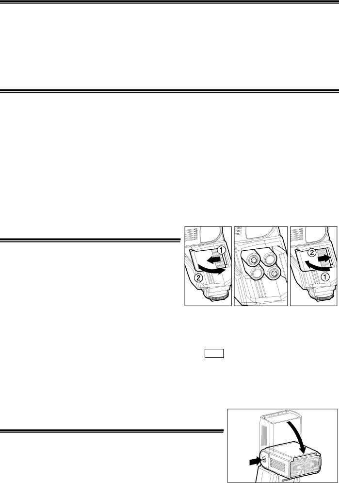
BATTERY LOADING
1.Be sure to set the Power Switch to the off position then slide, the battery cover in the direction of the arrow to open.
2.Insert four AA size batteries into the battery chamber. Be sure the + and – ends of the batteries are aligned according to the diagram in the chamber.
3.Close the cover.
4.Slide the Power Switch to the ON position. After few
seconds, the Ready Lamp will light, indicating that the flash unit can be fired.
5.Please press the “Test Button” to be sure that the flash is working properly.
AUTO POWER OFF
To conserve battery power, the flash unit automatically turns itself off when the flash is not used within approximately 5 minutes. To turn the flash on again, depress the TEST button or the camera shutter button, halfway. Please note that, “Auto Power Off” mechanism does not work with wireless TTL flash mode, normal slave flash, and designated slave flash modes.
ERROR INDICATION
If the battery power is not sufficient or there is electric information error between the camera and flash unit, the “Er” mark will blink on the LCD panel. When this occurs, turn the power switch off and on. If it still blinks, after this procedure, check the battery power.
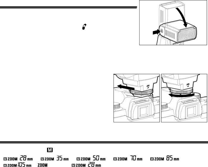
ADJUSTING THE FLASH HEAD
Depress the Bounce “Up and Down” Lock and Release Button, and adjust the flash head to the desired position.
■ appears on the LCD panel, when you turn on the flash, and if this mark blinks, then the flash head is adjusted to an incorrect position.
16
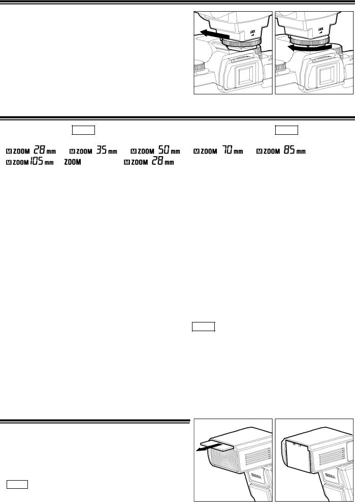
ATTACHING AND REMOVING THE FLASH TO AND FROM THE CAMERA
Be sure turn off the Power Switch. Then insert the Shoe
Base into the hot shoe on the camera and turn the Shoe
Locking Ring until it is tight.
■When you attach or remove the flash, grasp the bottom of the flash to prevent damage to the shoe foot and camera’s hot shoe.
■If the camera’s built-in flash is set in up position, please close it before you attach the flash unit.
■To remove the flash, rotate the shoe-locking ring in the opposite direction of ◄LOCK mark, until it stops.
SETTING OF FLASH COVERAGE ANGLE
When you press the ZOOM button  symbol appears. Each time you press the ZOOM button, the LCD panel display will change and indicate the zoom position in sequence, as follows.
Auto
Generally, in the TTL mode, the flash will automatically set the zoom position according to the focal length of your lens.
■When you turn on the main switch, the flash will memorize and set the zoom head position to the last setting used.
■If you use a lens wider than the flash head setting, there may be under exposed areas around the edge of the picture.
■Depending on the flash head setting, the flash’s Guide Number will be changed.
In the case of use with Sigma SD9 SD10
Due to the size of the camera’s image sensor, when the coverage angle of the flash is set to auto zoom, coverage angle can effectively reach that of 17mm wide focal length, without using the wide panel, (However, the coverage angle display of the flash will not show wider than 28mm). When the wide panel is used, 10mm focal length can be covered. (However, the coverage angle display on the flash will show 17mm.)
When "Manual Flash photography" or "FP Flash photography" is performed, the flash’s coverage angle can be set automatically by the flash’s autozoom function. However, when used with the camera, the effective range of the flash’s light can be extended by increasing the zoom setting of the flash to be equal to the effective focal length of the lens being used by using the ZOOM button. Please refer to the following table as a guide in setting the flash to the appropriate zoom setting. Please use this table in conjunction with Table 1 (“Guide Number Table for Manual Flash”) on the last page of this instruction manual, and Table 2 (“Guide Number Table for FP Flash”).
Lens’ Focal Length |
10-15mm |
16-19m |
20-29mm |
30-39mm |
40-49mm |
50-59mm |
60mm - |
|
m |
||||||||
|
|
|
|
|
|
|
||
Flash Coverage Angle |
17mm |
28mm |
35mm |
50mm |
70mm |
85mm |
105mm |
|
(given on the tables 1,2) |
withwide |
|||||||
|
|
|
|
|
|
|||
|
|
|
|
|
|
|
|
WIDE PANEL
This flash is equipped with built in type wide panel, which can provide ultra wide 17mm angle of coverage. Slide out the wide panel and flip it down to cover flash’s head. Then the coverage angle setting of the flash will be set to 17mm automatically.
■If the built-in wide panel comes off accidentally, the ZOOM button will not function. In this case please contact the store where you have purchased the flash,
17
or a service station.
18
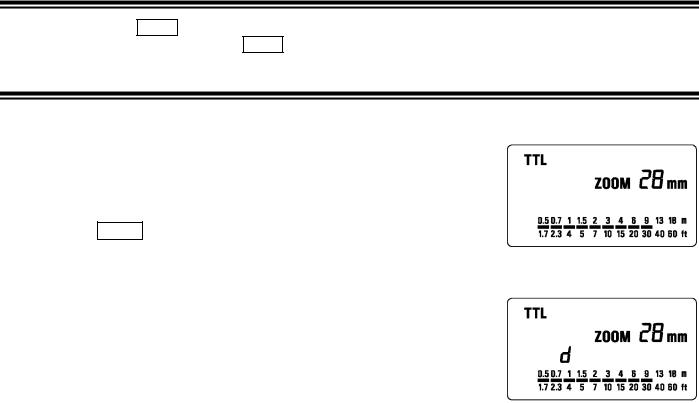
LCD PANEL ILLUMINATION
When you press the LIGHT button, the LCD panel will illuminate for about 8 seconds. The illumination stays on longer than 8sec, if you press the LIGHT button once again.
TTL AUTO FLASH
In the TTL AUTO Mode, the camera will control the amount of flash lighting to provide the appropriate exposure for the subject.
1.Set the camera’s exposure mode to P Mode. (In the case of SA-300, SA-300N and SA-5 set to “  ” fully automatic mode)
2.Turn on the power switch of the flash, the TTL mark will appear on the LCD panel and flash will start charging. (If TTL mark does not appear, depress the MODE button several times to select the TTL mode).
3.Focus on your subject.
4.Check that the subject is located within the effective distance range, indicated on the LCD panel.
5.Press the shutter button, after the flash is fully charged.
When the flash is fully charged, the ready light in the viewfinder, and appears on the flash unit.
■The TTL exposure is controlled by the S-TTL system of the digital camera. If the flash is set to TTL, the character "d" (digital) will be displayed on the LCD panel.
■When the camera receives the appropriate exposure, the TTL mark on the LCD panel will appear for 5 seconds. If this indication does not appear, the flash illumination is not enough for that situation. Please re-take the picture, at a closer distance.
■The AF Auxiliary Light will turn on automatically as you focus on a subject in a dark area. The effective range of the AF Auxiliary Light is up to about 0.7meter to 9meter (2.3-29.5 feet).
■If the SA-300, SA-300N and SA-5 cameras, are set to “ ” fully automatic mode, Flash will automatically switch to TTL mode only. For other camera exposure modes, the flash will be set to the last chosen mode each time.
■When the flash is fully charged, the flash mark will appear in the finder. If the shutter is released before the flash is fully charged, the flash will not fire, and the camera will take the picture at a slow shutter speed.
■If the flash range is below than 0.5meter (1.6 feet), the distance range bar marks on the LCD panel will blink.
USING FLASH IN OTHER CAMERA MODES
Shutter Speed Priority Setting
By selecting the S mode of the camera, you can set the shutter speed from 30sec. to 1/X sync speed. When you set the desired shutter speed, the camera will select the appropriate aperture value for the background. If the subject is too light or too dark, the aperture value indicator will blink and show the limit values (maximum or minimum aperture). In such as case, the camera proceeds to take flash photograph at the limit value. Thus, the main subject in the picture may be exposed correctly, but the background will become under or over exposed.
Aperture Priority Setting
By selecting the A mode of your camera, the camera will select the appropriate shutter speed for the background. If the subject is too bright or too dark, the shutter speed indicator will blink and show the limit highest or slowest shutter speed value. The highest shutter speed will be limited to the camera’s normal flash synchronization speed. In such a case, the camera proceeds to take a flash photograph at the limit value. Thus, the main subject in a picture may be exposed correctly, but the background will become under or overexposed.
When used with M Mode
You can set the desired shutter speed and aperture value. You can set the shutter speed from top sync speed to bulb. If you adjust the exposure according to the exposure meter indication, the camera will work as for Daylight synchronization flash or slow, synchronization.
19
■In the case of use with SD9, SD10, depending on the ISO setting, shutter speed will change to slow shutter speed side. For more detailed information, please refer to Exposure Mode selection.
LIMITS OF CONTINUOUS SHOOTING
To prevent overheating of the flash’s circuitry, please do not use your Flash unit for at least 10minutes after using the number of flash exposures, shown in the below table have been made in quick succession.
Mode |
Number of Flash Exposures |
TTL, M(1/1,1/2) |
15 Continuous Flash Shots |
M(1/4, 1/8) |
20 Continuous Flash Shots |
M(1/16-1/32) |
40 Continuous Flash Shots |
Multi |
10 Cycle |
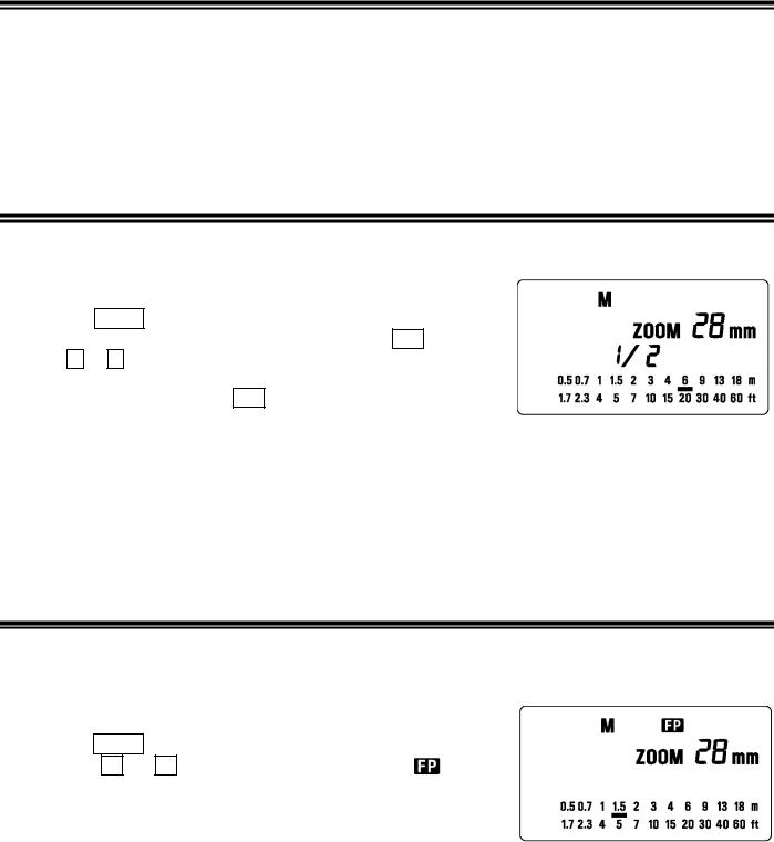
MANUAL FLASH OPERATION
Manual flash is provided when shooting the subjects when the correct, Exposure is difficult to obtain in the TTL mode. In the manual flash mode, you can set the flash power level from 1/1 (full) to 1/128 power in one step increments.
1.Set the camera’s exposure mode to M.
2.Press the MODE button on the flash unit to select M.
3.The guide number value blinks when you press the SEL button.
4.Press + or – button to set the desired flash power output.
5.The manual flash output display will stop blinking and remain displayed after you press the SEL button again.
6.Adjust the focusing by pressing the shutter button, read-out subject
distance from the focus ring on the lens. Then, adjust the F-stop or flash power, until the distance indicated on the LCD panel of the flash, and subject distance becomes about equal.
7.When the Ready Light of the flash is illuminated, the unit is ready for use.
■You can calculate the correct exposure by using the following formula: Guide Number “GN” / Flash to Subject Distance = F-stop
This flash unit will automatically calculate and indicate the appropriate Subject Distance according to the above formula. (Please refer to table1 on the last page)
FP FLASH (Except SA-300)
When you take a picture with an ordinary flash, you cannot use a shutter speed faster than the camera’s synchronized speed because the flash must fire when the shutter curtain is fully open. The FP flash keeps firing, while the shutter curtain is running. Thus you can use a shutter speed faster than the synchronized speed.
1.Set the camera’s exposure mode to M mode.
2.Press the MODE button on the flash unit, to select the M.
3.Press the + or – button and make the indicate |
indicator |
appear on the LCD panel.
4.Set the shutter speed.
5.Read-out the subject distance from the focus ring on the lens. Then, adjust the aperture value until the distance indicated on the LCD
panel of the flash matches the subject distance on the lens as closely as possible.
6.When the Ready Light of the flash is illuminated, the unit is ready for use.
■Depending on the shutter speed, the Guide Number will be changed.(Please refer to table2 on the last page)
■When you use the FP flash, do not use the Wide Panel.
■You cannot set the Second Curtain Synchronization while the flash unit is set on FP Flash
■If you want to cancel the FP Flash mode, please follow the FP flash procedure to make the  indicator display from the LCD panel.
20
SECOND CURTAIN SYNCHRONIZATION
When you photograph a moving subject with slow synchronization, usually the furrow of the subject will be exposed in front of the subject. The ordinary flash light will fire when the first shutter curtain is fully opened, thus the subject will be exposed from the time flash is fired to the time the shutter is closed (This is called First Curtain Synchronization). When you use second curtain synchronization, the flash will fire just before the second curtain begins to closes, and the subject will be exposed by ambient light from the time the shutter opens until the flash fires. The furrow of the subject will therefore be exposed behind the subject, creating a more natural effect.
1.Set the desired picture-taking mode of the camera
2.Select the Mode of the flash. (TTL, M modes. SD9 and SD10 can be used in M mode only)
3.Press + or – , button  mark will be displayed on the LCD panel.
4.Adjust the focus, and take the picture after confirming the ready light is lit.
■First curtain synchronization will be set, if  mark is not displayed.
■In the Full Auto Mode “  ” of SA-300, SA-300N, SA-5 cameras, this function cannot be used.
■To cancel second –curtain synchronization, turn off the  mark on the LCD panel.
RED-EYE REDUCTION
When you take a picture with flash, sometimes the person’s eyes reflect the flashlight and will exhibit “red-eye” in the picture. If you use the function of “Red-eye reduction”, the flash will blink approximately 1 second before the shutter is released, and reduce the “red-eye”.
1.Press the MODE Select the mode of the flash(TTL, M modes)
2.Press + or – , button and make  mark displayed on the LCD panel.
3.Adjust the focus, and take the picture after confirming the ready light is lit.
■To cancel the “Red-eye reduction” turn of the  mark.
mark.
■In the Full Auto Mode “  ” of SA-300, SA-300N, SA-5 cameras, this function cannot be used.
MODELING FLASH
If you use the Modeling flash, you can check the lighting and shadow effects, before you take the picture.
1.Press the MODE button and select the mode.
2.Press the + button or – button several times to make the  icon on the LCD panel appear.
3.Confirm that the flash is charged, then press the TEST button to fire.
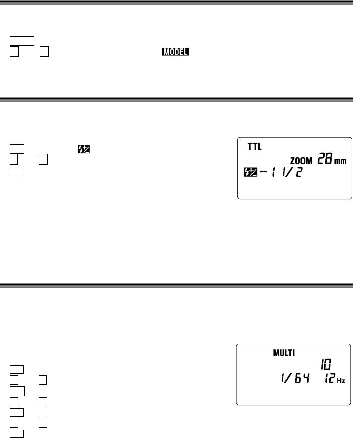
EXPOSURE COMPENSATION
You can use flash exposure compensation in combination with normal exposure compensation (to control the background exposure level) in flash picture. Flash exposure compensation can be set 1/2 stops (1/3 stops with SD10) in ±3-stop increments.
1.Press the MODE button and select the TTL mode.
2.Press the SEL button to make the indicator of  mark blink.
3.Press the + button or – button to set the compensation amount.
4.Press the SEL button to make compensation amount indicator stop blinking.
5.Focus on the subject.
6.Please check that the subject is within the flash range displayed on the EF 500 DG SUPER SA-N’s LCD panel.
7.You can take the picture after confirming that the Ready Light of the flash is illuminated.
21

■When you set the exposure compensation on the camera, both the flash power level and background can be compensated.
■You can use both exposure compensation by flash, and exposure compensation by camera at the same time.
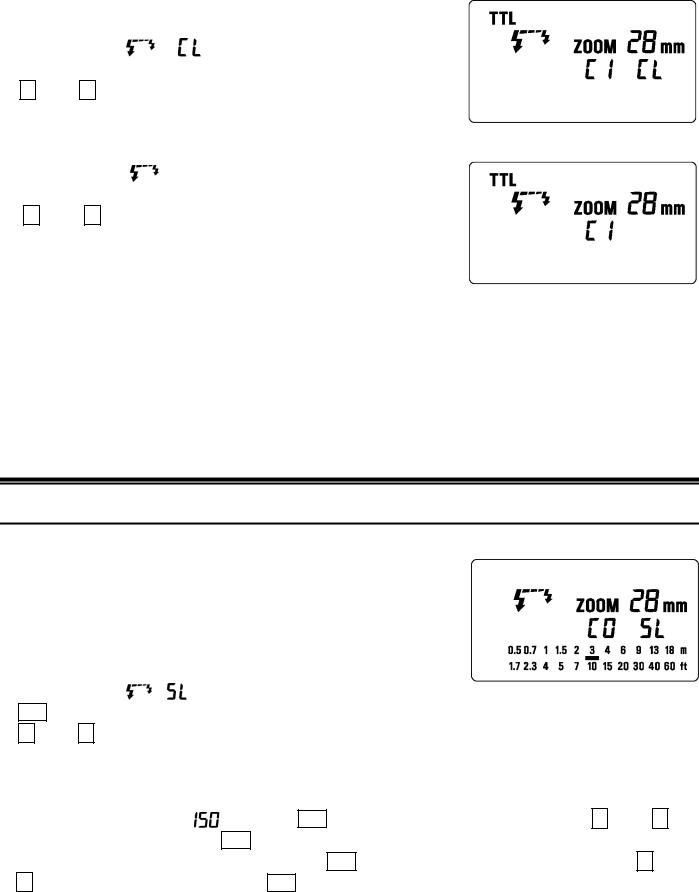
MULTI FLASH MODE
While the shutter is open, the flash will fire repeatedly. By doing so a series of images of the subject will be exposed in one frame. A dark background with a bright subject shows more effectively in this mode. It is possible to set the firing frequency between 1Hz and 199Hz. Up to 100 flashes can be fired continuously. The maximum number of flashes varies, depending on the flash guide number and firing frequency settings. (Please refer to table 3 on the last page)
1.Set the camera’s exposure mode to M mode, and set the F number
2.Press the MODE button until the Multi-flash mode appears
3.Press the SEL button until the flash firing frequency starts to blink.
4.Press the + or – button to set the desired flash frequency value.
5.After pressing the SEL button again, the flash power level will blink.
6.Press the + or – button to set the desired power level.
7.Press the SEL button again, the number of flashes will blink.
8.Press the + or – button to set the desired number of flashes.
9.Press the SEL button again, the display will stop blinking.
10.When the ready light of the flash is illuminated, the unit is ready to use.
Note: Please set the shutter speed longer than; Number of Flashes you want Firing Frequency
BOUNCE FLASH
When you take a photo with flash in a room, sometimes a strong shadow will appear behind the subject, if you point the flash head upwards or sideways to reflect the light off the ceiling, wall etc. the subject will be illuminated softly. Press the lock button and adjust the flash head to set the bounce angle.
UP: 0°, 60°, 75°, 90° |
DOWN: 0°,7° |
RIGHT: 0°, 60°, 75°, 90 |
LEFT: 0°, 60°, 75°,90°, 120°, 150°, 180° |
When the bounce flash mode is activated, a bounce indicator  will appear on the LCD panel.
The picture will receive the color from the reflecting surface. Please choose a white surface for bouncing.
Depending on the reflecting surface, the subject distance and other factors, the effective distance range for the TTL AUTO may change. Please check for correct exposure confirmation ( TTL mark on the LCD panel) after releasing the shutter.
Close-up Exposures
For bounce flash can be tilted 7° downward for close-ups. The Flash will be effective only for the subjects 0.5 meter to 2 meters. When the flash head is tilted 7° will blink.
WIRELESS FLASH (Except SD9)
When you use the “Wireless Flash” mode, you can take pictures with a more three-dimensional feeling by shadow, or you can make natural image by shadow depending on the flash position, without any extension cord connecting the camera body and flash. In case of EF-500 DG SUPER SA-N, communication between the camera body and the flash will be done by the light of the flash. In the “Wireless Flash” mode, the camera will calculate the correct exposure automatically.
22

Control System Change
Control System of “Wireless Flash” is different for each camera. First it is necessary to attach the flashgun to the camera for activating the control system. If this operation is neglected, wireless function may not work when flashgun is separated from the camera.
1.Attach the flashgun to the camera and turn on the power switch of the flashgun and camera.
2.Press the shutter button of camera halfway. (The camera and flashgun communicate and control system will be switched automatically.)
3.Turn off the power switch of the flashgun and camera.
When Built-in Flash is Used (SA-7 and SA-9)
1.Press the MODE button to select the  mark.
mark.
2.Press the SEL button to make the channel indicator blink.
3. Press the + button or – button to set the channel.
4.Press the SEL button to stop the indicator blinking.
5.Place the EF-500 DG SUPER SA-N at the desired position.
■Do not place the flash unit within the picture area.
■Please be set the flash unit between 0.5m 5m (1.6 ~16ft) from the
subject, and set the camera body between 1m 5m (1.6~16ft) from the subject.
■Be sure to set the camera’s flash mode to “Wireless Flash Mode”, and set the channel number on the EF-500 DG SUPER SA-N Flash unit to the same channel number as that you set on the camera. Otherwise, the EF-500 DG SUPER SA-N and your camera will not communicate with each other and the EF-500 DG SUPER SA-N will not fire, when you take picture.
6.Pop-up the camera’s built-in flash, and then after both flashes are fully charged, press the shutter button to take the picture.
■AF Auxiliary Light on the EF-500 DG SUPER SA-N will blink, when the flash unit charged and is ready to fire.
■The EF-500 DG SUPER SA-N will fire when the built-in flash fires. The camera’s built-in flash is fired only to control the EF-500 DG SUPER SA-N only. The flash lighting of the subject is done by the EF-500 DG SUPER SA-N. The camera will control the flash power level, as a TTL mode flash, to Obtain correct exposure.
Cameras not equipped with built-in flash used (SD10)
For Wireless flash two pieces of EF-500 DG SUPER SA-N will be necessary. In this instruction, we call a flash unit, which is attached to the camera body “Master unit ”, and we call a flash unit at a remote position “Slave unit”.
Master unit Setting
1.Attach the flash unit to the camera.
2.Press the MODE button to select  ⁄
⁄  mark.
mark.
3.Press SEL button, to make the channel indicator blink on the
display.
4. Press + or – button to set the desired channel number.
5. Press the SEL button several times until the display stops blinking.
Slave unit Setting
6.Press the MODE button to select  .
.
7.Press SEL button, to make the channel indicator blink, on the display.
8.Press + or – button to choose the same channel number as set on the Master unit.
9.Press the SEL button several times until the indicator stops blinking.
10.Place the Slave unit at the desired position.
11.Check that both flashes are fully charged.
■Ready light lamp will light, and the AF Auxiliary lamp will blink to indicate that the flash is ready for shooting.
12.Adjust the focus on the subject, and take the picture.
23
■Master unit fires just for controlling the Slave unit, and does not influence photography.
■When you set a slave unit at the desired position, you can use mini-stand. This mini-stand has a screw hole for a tripod.
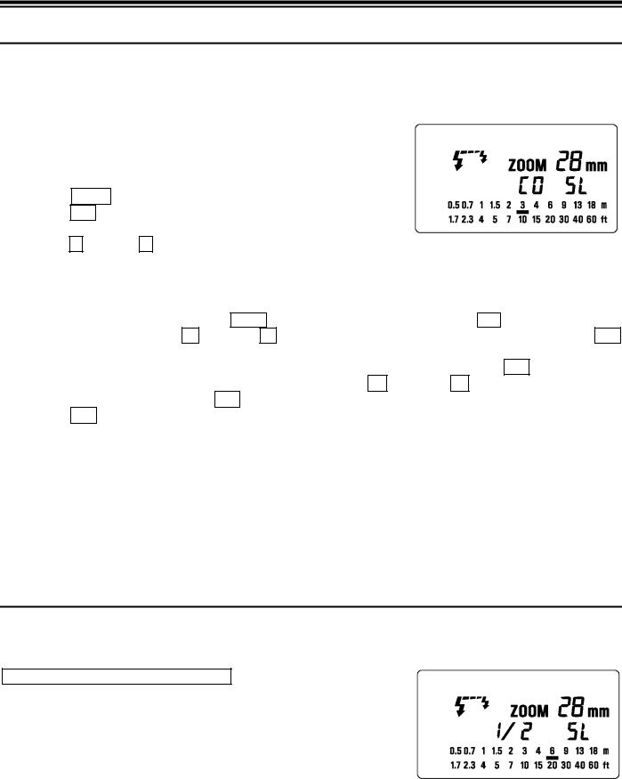
Slave Flash
Normal Slave Flash
Even if the EF-500 DG SUPER SA-N is not attached to the camera body, you can fire the flash by using the camera’s built-in flash or another flash unit
1.Attach the flash unit to the camera’s hot shoe.
2.Set the camera’s exposure mode to the desired mode. If you use A or M mode, set the desired aperture value also.
3.Turn on the flash unit. Then press the shutter button half way.
■Now, the aperture value and film speed are automatically transmitted to the flash unit.
4.Remove the flash unit from camera.
5.Press the MODE button and select the  /
/  (Slave) mode.
6.Press the SEL button several times to make the flash output amount indicator blink.
7.Press the + button or – button to set the flash output amount.
■Determine the appropriate flash power by setting the distance indicator on the LCD panel to coincide as closely as possible, with the actual distance from the slave flash to the subject. If the actual distance is out of range, you need to change the aperture value.
■You can set the film speed or aperture value on the flash unit manually, if desired.
a.For the film speed … Press the MODE to select the ISO, then press the SEL button to make the indicator blink. Press the + button or – button and set the desired film speed, then press the SEL button once again.
b.For the aperture value … When the flash unit is set to the Slave mode, press the SEL button to make the indicator for the aperture value blink, and press the + button or – button to set the desired
aperture value. Then press the SEL button.
8.Press the SEL button several times to make the display stop blinking.
9.Place the slave unit in the desired location. Do not place the slave unit within the Picture area.
10.After you confirm that all flash units are fully charged, press the shutter button to take the picture.
■When using the EF500 DG SUPER SA-N flash as the "Slave Controller" (on SD9 or SD10 camera) in Normal Slave mode, please set the flash to "Manual" mode, and adjust the light output to 1/16 power. If you set it to TTL mode instead, the Pre-Flash system will function, causing the "Slave" (off-camera) flash unit to fire prematurely.
■When the EF-500 DG SUPER SA-N is fully charged, the AF Auxiliary Light will blink.
■The flash will not fire if the EF-500 DG SUPER SA-N is attached to the camera body while it is in the Slave Mode setting.
Designated Slave Flash
If you use two or more EF-500 DG SUPER SA-N flash units, you can designate which flashes will fire together by using the channel settings. In this mode, one flash unit will be used as the Slave Controller and the others for firing as Slaves.
Setting the Slave Flash unit(s) for firing
1.Attach the firing flash unit to the camera body.
2.Set the camera’s exposure mode to S or M mode.
■Then set the shutter speed to 1/30 or slower. The slave Controller will transmit the designated signal before the others fire. Thus if you use a shutter speed faster than 1/30, the firing flash units will not be synchronized.
24

3. Switch “ON” the flash unit, and press the camera’s shutter button halfway.
■Now, aperture value and film speed are automatically transmitted to the slave flash unit.
4.Remove the slave flash unit from camera.
5.Press the MODE button and select the  /
/  . (Slave Mode)
6.Press the SEL button to make the channel display indicator blink.
7. Press the + button or – button to set the channel number. (C1 or C2)
8.Press the SEL button to make the output amount ( ) display indicator of flash blink.
9.Press the + button or – button to set the flash output amount.
■Set the flash power by setting the distance indicator on the LCD panel to coincide as closely as possible with the actual distance from the slave flash to the subject. If the actual distance is out of range, you need to change the aperture value.
10.Press the SEL button several times to make the display stop blinking.
11.Place the slave unit in the desired location. Do not place the slave unit within the picture area.
Setting for Slave Controller unit
12.Attach the Slave Controller flash unit to the camera body.
13.Press the MODE button and select the  /
/  (Slave Mode).
14.Press the SEL button to make the channel display indicator blink.
15.Press the + button or – button to set the same channel number as that set on the firing flash unit.
16.Press the SEL button to make the flash output amount ( ) display indicator blink.
17.Press the SEL button to make the display stop blinking. ( mark disappear and, channel display will appear)
18.After you confirm that all flash units are fully charged, press the shutter button to take the picture.
■When the firing flash unit of EF-500 DG SUPER SA-N is fully charged, the AF Auxiliary Light will blink.
■You cannot set the aperture value by SEL button, if you select the  mark at the setting of flash output amount. The flash unit will be set to the Slave Controller mode.
■The Slave Controller unit functions only to control the slave unit.
SPECIFICATIONS
TYPE : Clip-on type serial-controlled TTL auto zoom electric flash GUIDE NUMBER : 50 (ISO 100/m, 105mm head position)
POWER SOURCE : Four AA type alkaline batteries or, : Four AA type Ni-Cd batteries or, : Four AA type Ni-MH Nickel-Metal Hydride
RECYCLING TIME : about 6.0 sec. (Alkaline batteries)
: about 4.0 sec. (Ni-Cd, Ni-MH Nickel-Metal Hydride) NUMBER OF FLASHES : about 220 flashes (Alkaline batteries)
: about 100 flashes (Ni-Cd, Ni-MH Nickel-Metal Hydride) FLASH DURATION : about 1 / 700 sec. (full power firing)
FLASH ILLUMINATE ANGLE : 28mm - 105mm motor powered control (17mm with Built-in Wide Panel) AUTO POWER OFF : Available
COLOR TEMPERATURE : Suitable for Daylight type Color Films WEIGHT : 335 g / 11.8oz.
DIMENSIONS : 77mm(W)/3.0in. x 139mm(H)/5.5in. x 117mm(L)/4.6in.
25

DEUTSCH
Vielen Dank, dass Sie sich für ein SIGMA EF-500 DG SUPER SA-N SA Blitzgerät entschieden haben. Dieses Produkt wurde speziell für den Einsatz an den SIGMA SA und SD-Spiegelreflexkameraserie entwickelt. Abhängig von dem jeweiligen Kameramodell können Funktionen und Handhabung differieren. Bitte lesen Sie diese Gebrauchsanleitung bezogen auf Ihr Kameramodell sorgfältig durch. Um Ihre Freude an der Fotografie zu steigern, besitzt dieses Gerät eine Vielzahl von Ausstattungsmerkmalen. Sie sollten diese Gebrauchsanleitung im Zusammenhang mit Ihrer Kamerabedienungsanleitung studieren und für zukünftiges Nachschlagen griffbereit halten, um die Funktionen in vollem Umfang nutzen und die maximale Leistung des Gerätes ausschöpfen zu können.
Vorsichtsmaßnahmen
Um Verletzungen oder Beschädigungen zu verhindern, lesen Sie diese Bedienungsanleitung vor dem ersten Einsatz Ihres Blitzgerätes bitte sehr sorgfältig und vollständig durch und beachten Sie unbedingt die untenstehenden Warnzeichen. Bitte beachten Sie speziell die beiden folgenden Warnzeichen.
Warnung!! Wenn Sie die entsprechenden Hinweise nicht befolgen, kann dies zu ernsthaften Verletzungen oder anderen gefährlichen Folgen führen.
Achtung!! Wenn Sie die entsprechenden Hinweise nicht befolgen, können Verletzungen oder Schäden entstehen.
 Dieses Symbol verweist auf die wichtigen Punkte, an denen Vorsicht geboten ist.
  Dieses Symbol enthält Informationen bezüglich zu unterlassender Handlungen.
 Warnung!!
Dieses Blitzgerät enthält hochspannungsführende Schaltkreise. Um elektrische Schläge oder Verbrennungen zu vermeiden, versuchen Sie nicht, das Gerät zu öffnen. Sollte das äußere Gehäuse gebrochen oder zersprungen sein, berühren Sie keine inneren Geräteteile.
Blitzen Sie nicht aus kurzer Entfernung direkt in die Augen. Andernfalls kann das grelle Licht die Augen verletzen. Halten Sie beim Fotografieren zumindest einen Abstand von einem Meter zwischen Gesicht und Blitzgerät ein.
Benutzen Sie Ihre Ausrüstung nie in der Umgebung entflammbarer, brennbarer Gase, Flüssigkeiten oder Chemikalien etc. Andernfalls könnte dies zu einem Brand oder einer Explosion führen.
 Achtung!!
Benutzen Sie dieses Blitzgerät nicht an einer anderen Kamera als an einer der SIGMA SA, SD-Serie; andernfalls könnte der Blitz die Schaltkreise der Kamera beschädigen.
Dieses Blitzgerät ist nicht wasserdicht. Wenn Sie die Ausrüstung im Regen, Schnee oder in der Nähe von Wasser verwenden, bewahren Sie sie davor, nass zu werden. Es ist häufig unmöglich, Wasserschäden interner elektrischer Komponenten zu reparieren.
Setzen Sie das Blitzgerät niemals Stößen, Staub, Hitze oder Feuchtigkeit aus. Diese Faktoren könnten einen Brand oder Fehlfunktionen Ihrer Ausrüstung verursachen.
Wenn das Gerät plötzlichen Temperaturschwankungen ausgesetzt, etwa aus einer kalten Umgebung in einen warmen Innenraum gebracht wird, kann sich Kondensniederschlag im Inneren des Gerätes bilden. In solchen Fällen stecken Sie das Gerät bitte vor dem Temperaturwechsel in eine zu verschließende Plastiktasche und benutzen Sie es erst wieder, wenn es sich der Raumtemperatur angepasst hat.
Bewahren Sie das Gerät nicht in einer Schublade oder einem Schrank auf, wo es schädlichen Dämpfen wie derer von Naphthalin, Kampfer oder Insektiziden ausgesetzt ist.
Verwenden Sie weder Verdünner, Benzin noch andere Reinigungsmittel, um Schmutz oder Fingerabdrücke von dem Gerät zu entfernen. Benutzen Sie ein weiches, gegebenenfalls angefeuchtetes, fusselfreies Tuch.
Bewahren Sie das Blitzgerät an einem trockenen, kühlen und gut belüfteten Ort auf. Lösen Sie den Blitz von Zeit zu Zeit aus, um seine volle Leistungsfähigkeit langfristig zu erhalten.
26

Beschreibung der Teile
Externe Teile
1.Blitzkopf 2.Eingebaute Weitwinkel-Streuscheibe 3.AF-Hilfsilluminator 4.Verstellwinkel vertikal 5.Schwenkwinkel horizontal 6.Verstellver –u. entriegelung vertikal 7.Schwenkver –u. entriegelung horizontal 8.Flüssigkeitskristallanzeige 9.Batteriefachdeckel 10.Klemmrad 11.Aufsteckfuß
Bedienungselemente
12.Betriebsartentaste <MODE> 13.Wahltaste <SEL> 14.<+> Steigerungstaste 15.<-> Reduzierungstaste 16.ZOOM Taste <ZOOM> 17.Testauslöser <TEST> 18.Beleuchtungstaste <LIGHT> 19.Bereitschaftslampe 20.Hauptschalter
Batteriehinweise
Dieses Blitzgerät benötigt vier „AA“ Alkaline Trockenbatterien oder wiederaufladbare Ni-Cad oder Ni-MH Akkus. Wechseln Sie den kompletten Batteriesatz aus, wenn die Aufladezeit mehr als 30 Sekunden beträgt.
■Um einwandfreien elektrischen Kontakt zu gewährleisten, reinigen Sie die Batteriekontakte, bevor Sie die Batterien einsetzen.
■NiCad Akkus besitzen keine standardisierten Kontakte. Falls Sie NiCad Akkus verwenden, vergewissern Sie sich, dass die Batteriekontakte jene des Batteriefaches einwandfrei berühren.
■Verwenden Sie ausschließlich vier frische „AA“ Mignonzellen einer Marke und eines Typs, um die Gefahr des Platzens einer Batterie, des Austritts von Batteriesäure oder der Überhitzung vorzubeugen. Mischen Sie keinesfalls frische und gebrauchte Batterien.
■Batterien dürfen weder geöffnet, noch kurzgeschlossen bzw. ins Feuer geworfen werden, da sie explodieren können. Zur Wiederaufladung dürfen nur hierfür geeignete Zellen verwendet werden, wie etwa NiCad.
■Wenn Sie das Blitzgerät längere Zeit nicht benutzen wollen, entnehmen Sie bitte die Batterien, um Schäden durch austretende Batteriesäure zu verhindern.
■Bei niedrigen Temperaturen lässt die Leistung jeder Batterie nach. Bewahren Sie die Batterien daher bei kalter Witterung bis zur Aufnahme getrennt vom Blitzgerät möglichst körperwarm auf.
■Wie bei jedem Blitzgerät empfiehlt sich die Mitnahme von Ersatzbatterien auf einer Reise oder für Außenaufnahmen bei winterlichen Temperaturen.
Einlegen der Batterien
1.Vergewissern Sie sich, dass der Hauptschalter auf OFF steht und öffnen Sie den Batteriefachdeckel durch Schieben in Pfeilrichtung und klappen Sie ihn nach oben.
2.Setzen Sie vier Mignonzellen Typ „AA“ entsprechend der Markierung der Polung (+ und -) in das Batteriefach ein.
3.Schließen Sie den Batteriefachdeckel.
4.Schalten Sie das Gerät am Hauptschalter ein. Nach einigen Sekunden leuchtet die Blitzbereitschaftslampe auf und zeigt somit an, dass das Gerät nunmehr zündbereit ist.
5.Um sich von der Funktionsfähigkeit durch einen Probeblitz zu überzeugen, genügt ein Druck auf den Testauslöser.
Automatische Abschaltung
Um Strom zu sparen, schaltet sich das Gerät 5 Minuten nach der letzten Betätigung automatisch ab. Zur Wiedereinschaltung genügt ein Druck auf den Testauslöser oder das Antippen des Kameraauslösers. Die automatische Abschaltung steht nicht im kabellosen Blitzbetrieb zur Verfügung.
Fehleranzeige
Bei ungenügender Batteriespannung bzw. fehlerhaftem Informationsaustausch zwischen Kamera und Blitzgerät erscheint “Er” in der LCD. Schalten Sie das Gerät in diesem Fall kurzfristig aus und wieder ein. Führt dies nicht zum Erlöschen der Anzeige, prüfen Sie bitte die Batteriespannung.
Einstellen des Blitzkopfes
Drücken Sie die Verstellwinkelverund -entriegelungstaste, während
Sie den Blitzkopf in die gewünschte Position neigen.
■Wenn Sie das Gerät einschalten, erscheint  auf dem LCD. Sollte das Symbol blinken, befindet sich der Blitzkopf in einer unzulässigen Position.
27
 Loading...