


COAGULATION
ANALYZER
OPERATION MANUAL
Instrument manufactured by
Sigma Amelung,
Lemgo, Germany
REVISION DATE 10/23/01

SIGMA DIAGNOSTICS INSTRUMENT WARRANTY
Sigma-Aldrich Co., Inc. ("Sigma"), warrants that instruments it sells to be free from defects in workmanship and materials during normal use by the original purchaser.
This Warranty shall continue for a period of one year from the date of invoice to the original purchaser, or until title is transferred from the original purchaser, whichever occurs first (the "Warranty Period").
If any defects occur during the Warranty Period, contact the Sigma Service Center immediately, and be prepared to furnish pertinent details concerning the defect, the model number, and the serial number.
Warranty service is provided 8:30 a.m. through 5:00 p.m., Monday through Friday, except on Sigma observed holidays. Any service performed at other times, and all service required to correct defects or malfunctions not covered by this Warranty, will be billed on a time-and-material basis at Sigma's labor rates then in effect.
This Warranty does not cover defects or malfunctions which: (1) are not reported to Sigma during the Warranty Period and within one week of occurrence; (2) result from chemical decomposition or corrosion; (3) are described in the applicable Sigma Operation Guide; (4) result from maintenance, repair, or modification performed without Sigma's prior written authorization; or (5) result from misuse, abuse or accident.
Sigma's liability for all matters arising from the supply, installation, use, repair, and maintenance of the instrument, whether arising under this Warranty or otherwise, shall be limited solely to the repair or (at Sigma's sole discretion) replacement of the instrument or of components thereof. In no event shall Sigma be liable for injuries sustained by third parties, incidental or consequential damages, or lost profits.
Replaced parts shall become the property of Sigma.
THE FOREGOING IS THE SOLE WARRANTY MADE BY SIGMA REGARDING THE INSTRUMENT, AND SIGMA SPECIFICALLY DISCLAIMS ALL OTHER WARRANTIES, EXPRESSED OR IMPLIED, INCLUDING THE WARRANTIES OF MERCHANTABILITY AND OF FITNESS FOR A PARTICULAR PURPOSE.
KC4 ∆™ User Manual, October 2001
(Software Version 1.1B)
© 2001 Sigma-Aldrich Co.
October 2001 |
EN |

KC4 ∆™ |
|
|
|
|
|
|
0 |
|
|
Table of Contents |
|
|
|
|
|
|
|
|
|
|
|
|
|
|
1 INTRODUCTION.................................................................................................... |
1-1 |
|
1.1 |
INTENDED USE ................................................................................................. |
1-1 |
1.2 |
PRINCIPLES OF OPERATION.............................................................................. |
1-1 |
1.3 |
PHYSICAL SPECIFICATIONS .............................................................................. |
1-2 |
1.4 |
PERFORMANCE SPECIFICATIONS ..................................................................... |
1-3 |
1.5 |
PHYSICAL DESCRIPTION ................................................................................... |
1-6 |
1.6 |
FRONT VIEW (FIGURE 1) ................................................................................... |
1-7 |
1.7 |
KEYPAD (FIGURE 2)........................................................................................... |
1-8 |
1.8 |
BACK VIEW (FIGURE 3) ..................................................................................... |
1-9 |
1.9 |
MULTIPETTE (FIGURE 4 A & B) ....................................................................... |
1-10 |
1.10 |
BALL DISPENSER (FIGURE 5) .......................................................................... |
1-11 |
1.11 |
THERMAL PRINTER (FIGURE 6) ....................................................................... |
1-11 |
1.12 |
PRINTER OPTIONS........................................................................................... |
1-12 |
2 INSTALLATION ..................................................................................................... |
2-1 |
|
2.1 |
UNPACKING ....................................................................................................... |
2-1 |
2.2 |
KC4 ∆™ COAGULATION ANALYZER START-UP KIT ............................................ |
2-1 |
2.3 |
LOCATION REQUIREMENTS .............................................................................. |
2-2 |
2.4 |
ELECTRICAL REQUIREMENTS .......................................................................... |
2-2 |
2.5 |
PRELIMINARY CHECK OF THE INSTRUMENT OPERATION ................................ |
2-3 |
3 GENERAL OPERATION ......................................................................................... |
3-1 |
|
3.1 |
INSTRUMENT PREPARATION ............................................................................. |
3-1 |
3.2 |
TEMPERATURE INDICATOR SCREEN ................................................................ |
3-1 |
3.3 |
MAIN MENU FUNCTIONS ................................................................................... |
3-2 |
3.4 |
PASSWORD MODIFICATION .............................................................................. |
3-2 |
3.5 |
PROGRAM MODIFICATION ................................................................................ |
3-3 |
3.6 |
REAGENT HANDLING ........................................................................................ |
3-4 |
3.7 |
CUVETTE PREPARATION ................................................................................... |
3-4 |
3.8 |
SAMPLE PREPARATION ..................................................................................... |
3-5 |
3.9 |
PIPETTING ......................................................................................................... |
3-6 |
3.10 |
TO DISPENSE SAMPLE ...................................................................................... |
3-7 |
3.11 |
TO DISPENSE FIRST REAGENT ......................................................................... |
3-8 |
3.12 |
TO DISPENSE START REAGENT ........................................................................ |
3-9 |
3.13 |
SELECTING A TEST TO BEGIN A RUN ............................................................. |
3-10 |
3.14 |
PATIENT IDENTIFICATION ............................................................................... |
3-11 |
3.15 |
TESTING .......................................................................................................... |
3-11 |
3.16 |
MANUAL START PROCEDURE ......................................................................... |
3-12 |
3.17 |
AUTOMATIC START PROCEDURE.................................................................... |
3-12 |
3.18 |
PRINTING RESULTS ......................................................................................... |
3-13 |
4 MODE PROGRAMMING ......................................................................................... |
4-1 |
|
4.1 |
ROUTINE PROGRAMMING ................................................................................. |
4-1 |
4.2 |
EMERGENCY PROGRAMMING ........................................................................... |
4-2 |
4.3 |
INDIVIDUAL PROGRAMMING............................................................................. |
4-3 |
October 2001 |
TOC-1 EN |

|
|
|
|
|
KC4 |
∆™ |
|
|
0 |
|
|
||
|
|
|
|
Table of Contents |
||
|
|
|
|
|
||
|
|
|
|
|
|
|
|
|
|
|
|
|
|
5 |
TEST PROGRAMMING........................................................................................... |
5-1 |
||||
|
|
5.1 |
INR .................................................................................................................... |
5-1 |
||
|
|
5.2 |
INR FLOW CHART.............................................................................................. |
5-3 |
||
|
|
5.3 |
PROTHROMBIN TIME (PERCENT ACTIVITY CURVE) .......................................... |
5-4 |
||
|
|
5.4 |
PT (PERCENT ACTIVITY) FLOW CHART.............................................................. |
5-7 |
||
|
|
5.5 |
RATIO FLOW CHART ......................................................................................... |
5-8 |
||
|
|
5.6 |
ACTIVATED PARTIAL THROMBOPLASTIN TIME................................................. |
5-9 |
||
|
|
5.7 |
APTT FLOW CHART ......................................................................................... |
5-11 |
||
|
|
5.8 |
FIBRINOGEN ................................................................................................... |
5-12 |
||
|
|
5.9 |
FIBRINOGEN FLOW CHART............................................................................. |
5-15 |
||
|
|
5.10 |
FACTORS......................................................................................................... |
5-16 |
||
|
|
5.11 |
FACTORS FLOW CHART .................................................................................. |
5-19 |
||
|
|
5.12 |
STATS.............................................................................................................. |
5-20 |
||
6 |
QUALITY CONTROL .............................................................................................. |
6-1 |
||||
7 |
MAINTENANCE ..................................................................................................... |
7-1 |
||||
8 |
TROUBLESHOOTING............................................................................................. |
8-1 |
||||
|
|
8.1 |
TROUBLESHOOTING FLOW DIAGRAM .............................................................. |
8-1 |
||
|
|
8.2 |
TROUBLESHOOTING PROCEDURES TABLE...................................................... |
8-1 |
||
A |
APPENDIX ............................................................................................................ |
A-1 |
||||
|
|
A.1 |
INR FAST TRACK ............................................................................................... |
A-1 |
||
|
|
A.2 |
APTT FAST TRACK............................................................................................. |
A-2 |
||
|
|
A.3 |
FIBRINOGEN FAST TRACK ................................................................................ |
A-3 |
||
|
|
A.4 |
FIBRINOGEN CALIBRATION CURVE DILUTION ................................................. |
A-4 |
||
|
|
A.5 |
EXTRINSIC FACTORS II, V, VII AND X FAST TRACK .......................................... |
A-5 |
||
|
|
A.6 |
EXTRINSIC FACTOR STANDARD CURVE DILUTIONS ........................................ |
A-6 |
||
|
|
A.7 |
INTRINSIC FACTORS VIII, IX, XI AND XII FAST TRACK ...................................... |
A-7 |
||
|
|
A.8 |
INTRINSIC FACTOR STANDARD CURVE DILUTIONS ......................................... |
A-8 |
||
TOC-2 EN |
October 2001 |

KC4 ∆™ |
|
|
|
|
|
|
1 |
|
|
Introduction |
|
|
|
|
|
|
|
|
|
|
|
|
|
|
Contents |
|
|
|
|
1.1 |
INTENDED USE...................................................................................... |
1-1 |
1.2 |
PRINCIPLES OF OPERATION.................................................................. |
1-1 |
1.3 |
PHYSICAL SPECIFICATIONS .................................................................. |
1-2 |
1.4 |
PERFORMANCE SPECIFICATIONS ......................................................... |
1-3 |
1.5 |
PHYSICAL DESCRIPTION ....................................................................... |
1-6 |
1.6 |
FRONT VIEW (FIGURE 1) ....................................................................... |
1-7 |
1.7 |
KEYPAD (FIGURE 2)............................................................................... |
1-8 |
1.8 |
BACK VIEW (FIGURE 3).......................................................................... |
1-9 |
1.9 |
MULTIPETTE (FIGURE 4 A & B)............................................................. |
1-10 |
1.10 |
BALL DISPENSER (FIGURE 5)............................................................... |
1-11 |
1.11 |
THERMAL PRINTER (FIGURE 6)........................................................... |
1-11 |
1.12 |
PRINTER OPTIONS ............................................................................... |
1-12 |
October 2001 |
1-0 EN |

KC4 ∆™ |
|
|
|
|
|
|
1 |
|
|
Introduction |
|
|
|
|
|
|
|
|
|
|
|
|
|
|
1.1Intended Use
The KC4 ∆™ Coagulation Analyzer is a semi-automated mechanical clot detection system designed for the determination of prothrombin times (PT), activated partial thromboplastin times (APTT), fibrinogen concentrations determined by Clauss methodology, and other clotting assays. Any clotting based assay, which has fibrin formation as its endpoint may be performed on the KC4 ∆™ Coagulation Analyzer. Measurement can be qualitative or quantitative. When used in conjunction with appropriate reagents, the sample can be plasma, or whole blood.
The additions of both sample and reagents are manual. Time measurement of the clotting endpoint is automated.
1.2Principles of Operation
The KC4 ∆™ is an electromechanical clot detection system. The system utilizes a special cuvette in which there is a stainless steel ball. Sample is added to the cuvette. After an appropriate incubation period, the cuvette is placed into the measuring well of the KC4 ∆™. The measuring well rotates slowly (50 rpm) causing the cuvette to rotate along its longitudinal axis. Because the cuvette is positioned at a slight angle, gravity and inertia always position the ball at the lowest point of the cuvette. Exactly opposite the ball-position is a magnetic sensor. With the addition of appropriate reagent, a timer is started. As coagulation takes place, fibrin strands form in the reaction mixture. The fibrin strands pull the ball away from its position and triggers an impulse in the magnetic sensor. This impulse electronically stops the timer (see diagrams).
|
|
|
|
|
|
|
|
|
|
|
|
|
|
|
|
|
|
|
|
|
|
|
|
|
|
|
|
|
|
|
|
|
|
|
|
|
|
|
|
|
|
|
|
|
|
|
|
|
|
|
|
|
|
|
|
|
|
|
|
|
|
|
|
|
|
|
|
|
|
|
|
|
|
|
|
|
|
|
|
|
|
|
|
|
|
|
|
|
|
|
|
|
|
|
|
|
|
|
|
|
|
|
|
|
|
|
|
|
|
|
|
|
|
|
|
|
|
|
|
|
|
|
|
|
|
|
|
|
|
|
|
|
|
|
|
|
|
|
|
|
|
|
|
|
|
|
|
|
|
|
|
|
|
|
|
|
|
|
|
|
|
|
|
|
|
|
|
|
|
|
|
|
|
|
|
|
|
|
|
|
|
|
|
|
|
October 2001 |
|
|
|
|
|
|
|
|
|
|
|
|
|
|
|
|
|
|
|
|
|
|
|
|
|
|
1-1 EN |
|||

|
|
|
|
KC4 |
∆™ |
|
1 |
|
|
||
|
|
|
Introduction |
||
|
|
|
|
||
|
|
|
|
|
|
1.3Physical Specifications
Type: |
Coagulation Analyzer, Bench Top |
Online: |
Unidirectional |
Principle: |
Ball Method |
Measuring Channels: |
4 |
Display: |
LCD |
Incubation Wells: |
8 |
Reagent Wells: |
5 |
Dimensions |
|
Height: |
12.0 cm |
Width: |
35.4 cm |
Depth: |
45.0 cm |
Weight |
6.3 kg |
Power Supply |
|
Voltage |
110–220V/50–60 HZ |
Power Consumption |
1.5A at 100V; 0.4A at 220V |
Temperature Control |
|
Reagent Warming Wells: |
37.0°C ± 0.5°C |
Reaction Incubation Wells: |
37.0°C ± 0.5°C |
Measurement Wells: |
37.0°C ± 0.5°C |
Measurement Time |
|
Minimum: |
4.5 seconds |
Maximum: |
999.9 seconds |
1-2 EN |
October 2001 |
KC4 ∆™ |
|
|
|
|
|
|
1 |
|
|
Introduction |
|
|
|
|
|
|
|
|
|
|
|
|
|
|
1.4Performance Specifications
The overall performance of any testing performed on the KC4 ∆™ Coagulation Analyzer is dependent not only on the instrument performance, but is also a function of specimen integrity (collection and handling) as well as accuracy and precision of the sample and reagent dispensing system being used.
Correlation:
The following linear regression data was obtained during evaluation to show equivalence with a commercially available mechanical coagulation analyzer.
|
|
Activated Partial |
|
Prothrombin Time |
Thromboplastin Time |
Number of Samples |
121 |
110 |
Correlation Coefficient (r) |
0.998 |
0.896 |
Slope |
1.051 |
1.235 |
Intercept |
–0.241 |
0.873 |
The following linear regression data was obtained during evaluation to show equivalence with a commercially available photo-optical coagulation analyzer.
|
Fibrinogen |
Factor X |
Factor IX |
Number of Samples |
109 |
112 |
101 |
Correlation Coefficient (r) |
0.930 |
0.974 |
0.897 |
Slope |
1.067 |
1.010 |
0.958 |
Intercept |
30.749 |
–0.166 |
3.403 |
The following linear regression data was obtained in three physician’s office laboratories (POL) during evaluation to show equivalence with manufacturer derived results on the KC4 ∆™ Coagulation Analyzer.
|
|
Activated Partial |
POL #1 |
Prothrombin Time |
Thromboplastin Time |
Number of Samples |
47 |
44 |
Correlation Coefficient (r) |
0.991 |
0.960 |
Slope |
0.981 |
1.066 |
Intercept |
0.492 |
0.379 |
|
|
Activated Partial |
POL #2 |
Prothrombin Time |
Thromboplastin Time |
|
|
|
Number of Samples |
45 |
46 |
Correlation Coefficient (r) |
0.989 |
0.965 |
Slope |
1.019 |
1.029 |
Intercept |
–0.248 |
1.021 |
October 2001 |
1-3 EN |

|
|
|
|
KC4 |
∆™ |
|
1 |
|
|
||
|
|
|
Introduction |
||
|
|
|
|
||
|
|
|
|
|
|
|
|
Activated Partial |
POL #3 |
Prothrombin Time |
Thromboplastin Time |
Number of Samples |
52 |
47 |
Correlation Coefficient (r) |
0.974 |
0.927 |
Slope |
1.012 |
0.786 |
Intercept |
0.326 |
9.470 |
Precision: Prothrombin Time (PT)
Imprecision was evaluated at three levels according to the NCCLS EP5-T2 protocol.
|
Low |
Mid |
High |
Mean (seconds) |
13.20 |
33.53 |
39.66 |
Total Imprecision (CV%) |
2.03 |
2.50 |
4.18 |
Within-Run Imprecision (CV%) |
1.02 |
1.28 |
1.53 |
PT total imprecision was evaluated in three physician’s office laboratories (POL) at three levels according to NCCLS EP10-T protocol. Within-Run imprecision was evaluated in three physician’s office laboratories at two levels.
POL #1 |
Low |
Mid |
High |
Mean (seconds) |
13.1 |
26.8 |
42.9 |
Total Imprecision (CV%) |
1.97 |
1.63 |
2.47 |
Mean (seconds) |
12.7 |
|
44.1 |
Within-Run Imprecision (CV%) |
1.3 |
|
1.1 |
POL #2 |
Low |
Mid |
High |
Mean (seconds) |
12.1 |
23.3 |
40.7 |
Total Imprecision (CV%) |
2.59 |
7.12 |
3.0 |
Mean (seconds) |
12.1 |
|
41.7 |
Within-Run Imprecision (CV%) |
2.6 |
|
1.8 |
POL #3 |
Low |
Mid |
High |
Mean (seconds) |
11.3 |
22.8 |
34.2 |
Total Imprecision (CV%) |
1.57 |
7.41 |
0.50 |
Mean (seconds) |
11.4 |
|
34.7 |
Within-Run Imprecision (CV%) |
2.0 |
|
1.3 |
1-4 EN |
October 2001 |

KC4 ∆™ |
|
|
|
|
|
|
1 |
|
|
Introduction |
|
|
|
|
|
|
|
|
|
|
|
|
|
|
Precision: Activated Partial Thromboplastin Time (APTT)
Imprecision was evaluated at three levels according to the EP5-T2 protocol.
|
Low |
Mid |
High |
Mean (seconds) |
28.55 |
51.01 |
75.78 |
Total Imprecision (CV%) |
3.12 |
3.41 |
3.21 |
Within-Run Imprecision (CV%) |
1.47 |
1.60 |
1.37 |
APTT total imprecision was evaluated in three physician’s office laboratories (POL) at three levels according to NCCLS EP10-T protocol. Within-Run imprecision was evaluated in three physician’s office laboratories at two levels.
POL #1 |
Low |
Mid |
High |
Mean (seconds) |
29.0 |
43.3 |
57.6 |
Total Imprecision (CV%) |
2.83 |
3.15 |
1.87 |
Mean (seconds) |
30.8 |
|
57.5 |
Within-Run Imprecision (CV%) |
2.7 |
|
1.6 |
POL #2 |
Low |
Mid |
High |
|
|
|
|
Mean (seconds) |
29.2 |
42.7 |
57.0 |
Total Imprecision (CV%) |
4.38 |
2.29 |
2.84 |
Mean (seconds) |
28.2 |
|
57.1 |
Within-Run Imprecision (CV%) |
2.1 |
|
1.7 |
POL #3 |
Low |
Mid |
High |
|
|
|
|
Mean (seconds) |
30.0 |
54.7 |
68.6 |
Total Imprecision (CV%) |
1.87 |
1.80 |
2.13 |
Mean (seconds) |
26.9 |
|
64.4 |
Within-Run Imprecision (CV%) |
1.4 |
|
2.5 |
Precision: Fibrinogen
Imprecision was evaluated at three levels according to the NCCLS EP5-T2 protocol.
|
Low |
Mid |
High |
Mean (mg/dl) |
104.09 |
154.10 |
323.53 |
Total Imprecision (CV%) |
3.53 |
6.21 |
4.36 |
Within-Run Imprecision (CV%) |
2.05 |
2.86 |
2.12 |
October 2001 |
1-5 EN |

|
|
|
|
KC4 |
∆™ |
|
1 |
|
|
||
|
|
|
Introduction |
||
|
|
|
|
||
|
|
|
|
|
|
Precision: Factor X
Imprecision was evaluated at three levels according to the NCCLS EP5-T2 protocol.
|
Low |
Mid |
High |
Mean (%) |
31 |
57 |
102 |
Total Imprecision (CV%) |
8.28 |
5.71 |
5.22 |
Within-Run Imprecision (CV%) |
2.63 |
2.22 |
2.20 |
Precision: Factor IX
Imprecision was evaluated at three levels according to the NCCLS EP5-T2 protocol.
|
Low |
Mid |
High |
Mean (%) |
24 |
49 |
98 |
Total Imprecision (CV%) |
5.88 |
6.89 |
4.06 |
Within-Run Imprecision (CV%) |
3.96 |
4.04 |
2.54 |
1.5Physical Description
The external features of the KC4 ∆™ Coagulation Analyzer are shown in Figure 1 (Front), Figure 2 (Keypad), Figure 3 (Rear), Figure 4 (Automatic Multipette with starter cable), Figure 5 (Ball Dispenser) and Figure 6 (Thermal Printer).
1-6 EN |
October 2001 |
KC4 ∆™ |
|
|
|
|
|
|
1 |
|
|
Introduction |
|
|
|
|
|
|
|
|
|
|
|
|
|
|
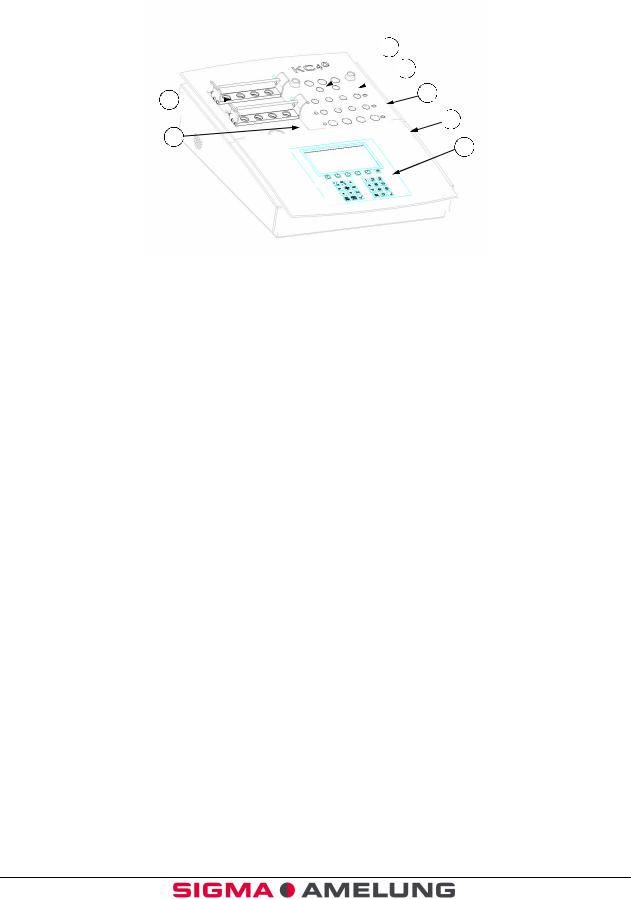
1.6Front View (Figure 1)
 3
3 
 4
4 
1 |
5 |
|
|
|
|
 6
6 
2

 7
7 
Item |
Function or Description |
|
1. |
Rack |
Used for transferring cuvettes from |
|
|
preparation area to reaction incubation |
|
|
wells and rotating test positions. |
2. |
Preparation Area |
Room temperature wells used for sample |
|
|
preparation prior to incubation. |
3. |
Pipette Tubes |
Used to store the pipettes when not in use. |
4. |
Reagent Warming Wells (5) |
Three 15 mm, and two 11 mm heated wells |
|
|
used to warm reagents. |
5. |
Reaction Incubation Wells (8) |
Heated wells used for incubation of sample |
|
|
and first reagent. |
6. |
Rotating Test Positions (4) |
Positions where start reagent is added and |
|
|
the clotting time is measured. |
7. |
Display Screen |
Displays elapsed time in seconds during |
|
|
incubation for each of 4 channels. Displays |
elapsed time in seconds and tenths of seconds during clot time measurement. Displays incubation times, clotting times, programming selections and other menus.
October 2001 |
1-7 EN |

|
|
|
|
KC4 |
∆™ |
|
1 |
|
|
||
|
|
|
Introduction |
||
|
|
|
|
||
|
|
|
|
|
|
1.7Keypad (Figure 2)
|
|
|
|
|
|
|
|
|
|
|
|
1 |
2 |
3 |
4 |
4 |
4 |
4 |
5 |
|
|
|
|
|
|
|
|
|
|
|
|
|
|
|
|
|
|
|
|
|
|
|
|
|
|
|
|
|
|
|
|
|
|
|
12
|
|
|
6 |
|
|
|
|
|
|
|
|
|
|
|
|
|
|
|
|
|
|
|
|
|
|
|
|
|
|
|
|
|
|
|
|
|
|
|
|
|
|
|
|
|
|
|
|
|
|
|
|
|
|
|
|
|
|
|
|
|
|
|
|
|
|
|
|
|
|
||
|
|
|
|
|
|
|
|
|
|
|
|
|
|
|
|
|
11 |
|
|
|
|
|
|
|
|
|
|
|
|
|
|
|
|
|
|
|
|
|
|
|
|
|
|
|
|
|
|
|
|
|
|
|
|
|
|
|
|
|
|
|
|
|
|
|
|
|
|
|
|
|
|
|
|
|
|
|
7 |
|
|
|
|
|
|
|
|
10 |
|
|
9 |
|
|
||||
|
|
|
|
|
|
|
|
|
|
|
|
|
|
|
|
|
|
|
|
|
|
|
|
|
|
|
|
|
|
|
|
|
|
|
|
|
|
|
|
|
|
|
|
|
|
|
|
|
|
|
|
|
|
|
|
|
|
|
|
|
|
|
8 |
|
|
|
|
|
|
|
|
|
Item |
|
|
|
|
|
|
|
|
Function or Description |
|
|
|
||||||||||
|
|
|
|
|
|
|
|
|
|
|
|
||||||||||||
|
|
|
|
|
|
|
|
|
|
|
|
|
|
|
|
|
|
|
|
|
|
|
|
1. |
Start Key |
|
|
|
|
|
|
|
|
Activates automatic measurement timer. |
|||||||||||||
2. |
Incubation Key |
|
|
|
|
|
|
|
|
|
|
|
Starts Incubation timers. |
|
|
|
|||||||
|
|
|
|
|
|
|
|
|
|
|
|
|
|||||||||||
|
|
|
|
|
|
|
|
|
|
|
|
|
|
||||||||||
|
|
|
|
|
|
|
|
|
|
|
|
||||||||||||
3. |
Ready Key |
|
|
|
|
|
|
|
|
Not functional at this time. |
|
|
|
||||||||||
4. |
Channel Key |
|
|
|
|
|
|
|
|
|
|
|
Starts manual timing and incubation. |
||||||||||
|
|
|
|
|
|
|
|
|
|
||||||||||||||
|
|
|
|
|
|
|
|
|
|
|
|||||||||||||
|
|
|
|
|
|
|
|
|
|||||||||||||||
5. |
Stop Key |
|
|
|
|
|
|
|
|
Terminates measurements, and aborts |
|||||||||||||
|
|
|
|
|
|
|
|
|
|
|
|
|
|
|
|
|
|
testing. |
|
|
|
||
6. |
Function Keys |
|
|
|
|
|
|
|
|
Used in programming tests. |
|
|
|
||||||||||
7. |
Menu Key |
|
|
|
|
|
|
|
|
Returns to Main Menu from Operating |
|||||||||||||
|
|
|
|
|
|
|
|
|
|
|
|
|
|
|
|
|
|
Screen. |
|
|
|
||
8. |
Run Key |
|
|
|
|
|
|
|
|
Returns to Test Program Selection Screen |
|||||||||||||
|
|
|
|
|
|
|
|
|
|
|
|
|
|
|
|
|
|
from Operating Screen. |
|
|
|
||
9. |
|
|
|
|
|
|
|
|
|
ENTER |
|
|
|
||||||||||
|
10. ESC Key |
|
|
|
|
|
|
|
|
Escapes back to previous function |
|||||||||||||
|
11. Printer Key |
|
|
|
|
|
|
|
|
Used to turn printer on or off |
|||||||||||||
|
12. Dilution Key |
|
|
|
|
|
|
|
|
Used to change the patient dilution. |
|||||||||||||
|
13. DEL key |
|
|
|
|
|
|
|
|
|
|
|
|
|
|
||||||||
|
|
|
|
|
|
|
|
|
|
|
|
|
|
|
|
|
|
|
|
|
|
|
|
|
1-8 EN |
|
|
|
|
|
|
|
|
|
|
|
October 2001 |
||||||||||

KC4 ∆™ |
|
|
|
|
|
|
1 |
|
|
Introduction |
|
|
|
|
|
|
|
|
|
|
|
|
|
|
1.8Back View (Figure 3)
3.
4.
|
|
2. |
1. |
Item |
Function or Description |
||
|
|
|
|
1. |
Thermal Printer Port |
Thermal Printer connection. |
|
2. |
Automatic Multipette Socket(s) |
Used to connect pipettes (Remove the cap- |
|
|
|
plug in the Multipette). |
|
3. |
Power Switch |
Powers instrument off/on. |
|
4. |
Power Supply Socket |
Connects instrument to power cord. |
|
October 2001 |
1-9 EN |
|
|
|
|
KC4 |
∆™ |
|
1 |
|
|
||
|
|
|
Introduction |
||
|
|
|
|
||
|
|
|
|
|
|
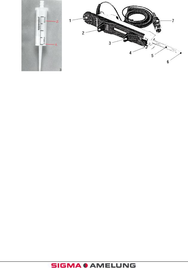
1.9Multipette (Figure 4 A & B)
|
Combitip |
Multipette |
|
4-A |
4-B |
Item 4-B |
Function or Description |
|
|
|
|
1. |
Volume selection dial |
Determines pipetting volume: setting (1–5) |
|
|
multiplied by the minimum pipetting |
|
|
volume of the Combitip (1.25 ml or 2.50 ml |
|
|
pipette tips). |
2. |
Pipetting lever |
The volume is pipetted by pressing the |
|
|
pipetting lever down until it stops. |
3. |
Filling lever |
The Combitip is filled by sliding this lever |
|
|
upward. |
4. |
Locking clamp |
The locking clamp serves to firmly clamp |
|
|
the Combitip. |
5. |
Combitip |
The pipette tip used with the automatic |
|
|
multipette. |
6. |
Combitip Cone |
Portion of the pipette tip that aspirates |
|
|
reagent. |
7. |
Starter Cable |
Connects pipette to instrument. |
1-10 EN |
October 2001 |

KC4 ∆™ |
|
|
|
|
|
|
1 |
|
|
Introduction |
|
|
|
|
|
|
|
|
|
|
|
|
|
|
1.10Ball Dispenser (Figure 5)
|
|
|
|
Item |
Description or Function |
||
|
|
|
|
1. Dispenser |
For loading microballs into cuvettes |
||
1.11Thermal Printer (Figure 6)
October 2001 |
1-11 EN |

|
|
|
|
KC4 |
∆™ |
|
1 |
|
|
||
|
|
|
Introduction |
||
|
|
|
|
||
|
|
|
|
|
|
1.12Printer Options
From the Main Menu, press < >. Press the <PRINTER> key. The (*) shows which options have been selected. If the analyzer is connected to a host LIS, ensure that option 4 is selected. If the analyzer is not connected to a host LIS, select 5.
Print Test Page |
1 |
Print Switch On |
2* |
Print Switch Off |
3 |
Line - out incl. Error Val. |
4* |
Line - out excl. Error Val. |
5 |
Press ENTER < > to continue
1-12 EN |
October 2001 |
KC4 ∆™ |
|
|
|
|
|
|
2 |
|
|
Installation |
|
|
|
|
|
|
|
|
|
|
|
|
|
|
Contents |
|
|
2.1 |
UNPACKING........................................................................................... |
2-1 |
2.2 |
KC4 ∆™ COAGULATION ANALYZER START-UP KIT ................................ |
2-1 |
2.3 |
LOCATION REQUIREMENTS................................................................... |
2-2 |
2.4 |
ELECTRICAL REQUIREMENTS............................................................... |
2-2 |
2.5 |
PRELIMINARY CHECK OF THE INSTRUMENT OPERATION..................... |
2-3 |
October 2001 |
2-0 EN |

KC4 ∆™ |
|
|
|
|
|
|
2 |
|
|
Installation |
|
|
|
|
|
|
|
|
|
|
|
|
|
|
2.1Unpacking
The KC4 ∆™ Coagulation Analyzer is shipped in a transport box designed to protect the instrument from damage during shipment. If damage is apparent, immediately notify the shipping company. Note the damage on the shipping bill of lading and notify your Sigma Diagnostics Sales Representative.
2.2KC4 ∆™ Coagulation Analyzer Start-Up Kit
Carefully remove the instrument and accessories from the transport box. Check that the following items have been included:
KC4 ∆™ Coagulation Analyzer
1.Power Cable
2.KC Micro Tetravettes
3.KC Delta Multipette with Starter Cable and Adapter Cord
4.Combitips (1.25 ml); 5 each
5.KC Pipette Tips, Yellow 200 l; 1 tray
6.Tubes, Plastic (14.5 x 85 mm); 100 each
7.Tubes, Glass (15 x 85 mm), 50 each
8.Power Supply 12V
9.Lead for Power Supply
10.Protective Dust Cover; 1 each
Optional Items |
|
|
Catalog Number |
Item |
|
1. |
P2864 |
KC Series Printer with Power Adapter |
2. |
K1638 * |
KC Series Thermal Printer Paper |
3. |
K4882 |
KC4 ∆™ Multipette with Starter Cable |
4. |
K0508 * |
KC4 ∆™ Combitips 1.25 ml |
5. |
K1510 * |
KC4 ∆™ Combitips 2.50 ml |
6. |
K4257 * |
KC Pipette Tips, Yellow, 200 l, 10 trays |
7. |
T9304 * |
Tubes, Glass (15 x 85 mm), 50 each |
8. |
K4887 * |
KC4 ∆™ Tetravettes |
9. |
T2242* |
Tubes, plastic (14.5 x 85 mm) |
10. |
K1635* |
KC Micro Cuvettes with Ball Dispencer |
11. |
A6083 |
Coated Stir Bar |
12. |
K6208 |
APTT Stir Bar |
13. |
K0633 |
KC Pittette Tube Sleeves |
|
|
|
October 2001 |
2-1 EN |
|

|
|
|
|
KC4 |
∆™ |
|
2 |
|
|
||
|
|
|
Installation |
||
|
|
|
|
||
|
|
|
|
|
|
*These are consumable items and should be ordered as needed.
Pipettes are required for the test performance. Although the use of a Multipette will ensure the start of the timing measurement is simultaneous with the addition of the reagent, it is not mandatory.
Read the Operation Manual carefully prior to using the KC4 ∆™ Coagulation Analyzer. The Operation Manual has been written to provide the most comprehensive understanding of the operation of the KC4 ∆™ Coagulation Analyzer and to enable you to fully utilize the features of the instrument.
2.3Location Requirements
1.Place the KC4 ∆™ Coagulation Analyzer on a stable, vibration and dust free work
surface. It should not be positioned next to a centrifuge or other equipment, which may cause vibration. The KC4 ∆™ Coagulation Analyzer should also be protected from moisture.
2.To avoid exceeding the control range of the instrument, place the KC4 ∆™ Coagulation Analyzer in an area with a maximum room temperature of 30°C.
It should not be positioned in an area directly below ventilating ducts which produce strong air currents. Do not expose the KC4 ∆™ Coagulation Analyzer to direct sunlight. Sunlight influences the temperature control.
3.It is preferable to place the KC4 ∆™ Coagulation Analyzer in an area which is no further than (6 ft.) 1.8 m from an electrical outlet. The instrument should not be operated from an extension cord which does not employ protective grounding. The electrical outlet used should not be shared with any devices, which consume large amounts of power on a cyclic basis (e.g., centrifuges, air conditioners, and refrigerators). When these type of devices cycle on and off, there may be a voltage drop in the line which could interfere with the proper functioning of the instrument.
2.4Electrical Requirements
The KC4 ∆™ Coagulation Analyzer is designed with a factory equipped three-pronged grounding plug designed to be connected to the Power Supply, which is then plugged into the analyzer. Under no circumstances should it be connected to an ungrounded two-pronged receptacle. This procedure is in accordance with the National Electrical Code and other applicable ordinances for this type of installation.
1.Do not use an extension cord which cannot to provide protective grounding.
2.It is recommended that any repair work other than routine maintenance be performed by a trained specialist familiar with the hazards involved.
3.If safe operation of the KC4 ∆™ Coagulation Analyzer is no longer possible, the instrument must be taken out of service.
2-2 EN |
October 2001 |

KC4 ∆™ |
|
|
|
|
|
|
2 |
|
|
Installation |
|
|
|
|
|
|
|
|
|
|
|
|
|
|
2.5Preliminary Check of the Instrument Operation
The preliminary function checks of instrument operation should be performed prior to using the instrument. This preliminary function check is to ensure that the instrument is functioning properly prior to reporting patient results.
1.Connect the power cable to the power cable socket on the back of the instrument (DC6.5V 2A).
2.Connect the Data Cable from the Serial Port on the Printer to the Printer port on the back of the Analyzer if utilizing the KC4 ∆™ printer.
3.Activate the KC4 ∆™ Coagulation Analyzer by pressing the off/on switch located on the left hand side of the back of the instrument.
4.Observe that the display screen lights up; a screen appears giving the operator the option to select the operating language. After the language selection, a screen showing a thermometer appears and will remain displayed while the instrument warms up to 37°C.
5.Observe that four of the measurement wells are rotating. The wells will rotate continuously whenever the instrument is on.
6.Place a KC4 ∆™ Micro cuvette or Tetravette into each position of the cuvette
rack. Place the cuvette rack on the rotating test positions such that the cuvettes are sitting flush in the holes. If using a KC4 ∆™ Micro cuvette, dispense one ball into each cuvette using the ball dispenser. Observe that the ball falls to the front of the cuvette and stays there.
7.Verification of temperature can be performed by placing approximately 3 ml of water into a 15-mm reagent tube. Place a thermometer into the tube and allow to equilibrate until the temperature has stabilized. Approximately 15 minutes will be required for temperature stabilization. The temperature should be
37° ± 0.5°C.
Note: The use of smaller diameter tubes is not recommended due to inadequate heat transfer.
8.To verify the operation of the timers, use the pipette with the start cable, and the measuring wells, a program modification is needed. From the Main Menu, select 3 Program Selection.
9.Enter the password; default password is 1 2 3 4. Press < >.
10.Select 4 Individual Program Modify; press TZ (Thrombin Clotting Time) key. Press < >.
11.To access the program settings, press < >. Press 2 (No) until “Test TZ” appears at the top of the screen. Press 1 (Yes) to modify TZ.
12.Enter 1 (duplicate testing), and 10% for allowed CV; press < > to continue.
13.Enter incubation time of 10 seconds, press < >. Press 2 (No) when modifications are done.
14.Press < > to continue. Press Run; select 3 Start Individual Program. Press TZ (Thrombin Clotting Time) key; press < >.
October 2001 |
2-3 EN |

|
|
|
|
KC4 |
∆™ |
|
2 |
|
|
||
|
|
|
Installation |
||
|
|
|
|
||
|
|
|
|
|
|
15.Enter 2 samples per rack; press < >. Press < > again to bring the Operating Screen up.
16.If the automatic Multipette with the starter cable is being used, plug the pipette cable connection into the pipette cable socket on the rear of the KC4 ∆™. Snap the locking mechanism on the Multipette into place.
17.Start timers by pressing the <START> key 

 , followed by the individual well timers


 . When all timers are showing 0.0, press and hold the <START>
key 

 , while at the same time, depress the trigger switch on the Multipette 4 times. All wells should begin timing.
18.After at least 10 seconds, remove the cuvette rack from the rotating test positions. Observe that the timers stop and are indicating the elapsed time in seconds and tenths of seconds.
19.The first result will print automatically (if the optional printer has been installed), or will appear on the screen. Press < > to print the second result, and clear the memory.
With the completion of the Preliminary Checks of Instrument Operation, installation is complete and the instrument is ready for operation. If the instrument fails to perform any of the tests with the specifications listed, call Sigma Diagnostics Technical Service for assistance.
2-4 EN |
October 2001 |

KC4 ∆™ |
|
|
|
|
|
|
3 |
|
|
General Operation |
|
|
|
|
|
|
|
|
|
|
|
|
|
|
Contents |
|
|
3.1 |
INSTRUMENT PREPARATION ................................................................. |
3-1 |
3.2 |
TEMPERATURE INDICATOR SCREEN..................................................... |
3-1 |
3.3 |
MAIN MENU FUNCTIONS........................................................................ |
3-2 |
3.4 |
PASSWORD MODIFICATION ................................................................... |
3-2 |
3.5 |
PROGRAM MODIFICATION..................................................................... |
3-3 |
3.6 |
REAGENT HANDLING............................................................................. |
3-4 |
3.7 |
CUVETTE PREPARATION ....................................................................... |
3-4 |
3.8 |
SAMPLE PREPARATION ......................................................................... |
3-5 |
3.9 |
PIPETTING ............................................................................................ |
3-6 |
3.10 |
TO DISPENSE SAMPLE........................................................................... |
3-7 |
3.11 |
TO DISPENSE FIRST REAGENT.............................................................. |
3-8 |
3.12 |
TO DISPENSE START REAGENT............................................................. |
3-9 |
3.13 |
SELECTING A TEST TO BEGIN A RUN ................................................... |
3-10 |
3.14 |
PATIENT IDENTIFICATION ................................................................... |
3-11 |
3.15 |
TESTING............................................................................................... |
3-11 |
3.16 |
MANUAL START PROCEDURE ............................................................... |
3-12 |
3.17 |
AUTOMATIC START PROCEDURE ......................................................... |
3-12 |
3.18 |
PRINTING RESULTS.............................................................................. |
3-13 |
October 2001 |
3-0 EN |
 Loading...